topic 7 control valves. what we will cover topic 1 introduction to process control topic 2...
TRANSCRIPT
Topic 7
Control Valves
What We Will Cover
Topic 1
Introduction To Process Control
Topic 2
Introduction To Process Dynamics
Topic 3
Plant Testing And Data Analysis
Topic 5Enhanced
Regulatory Control Strategies
Topic 7
Process Control Hardware Systems
Topic 4
Controller Actions And Tuning
Topic 7
Control Valves
Topic 8
Process Control Troubleshooting
Control Valves
Control valve construction
Valve types
Control valve characteristics
Valve failure characteristics
Control valve sizing
Control valve performance– Common problems– Testing
Control Valve Construction
The control valve is roughly divided into 2 parts– Actuator Assembly– Valve Body
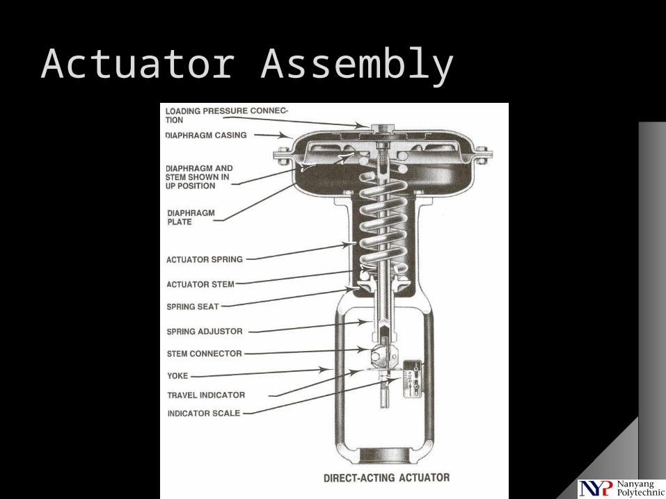
Actuator Assembly
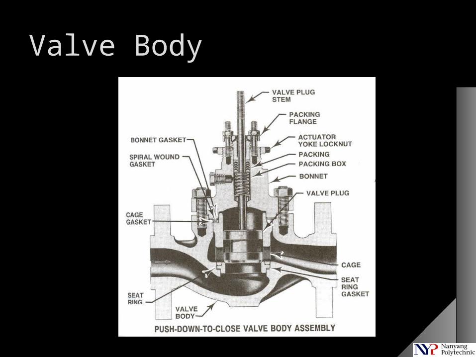
Valve Body
Valve types
Globe valve
Ball valve
Butterfly valve
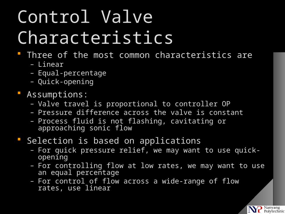
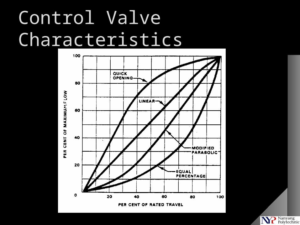
Control Valve Characteristics Three of the most common characteristics are
– Linear– Equal-percentage– Quick-opening
Assumptions:– Valve travel is proportional to controller OP– Pressure difference across the valve is constant– Process fluid is not flashing, cavitating or approaching sonic flow
Selection is based on applications– For quick pressure relief, we may want to use quick-opening– For controlling flow at low rates, we may want to use an equal
percentage– For control of flow across a wide-range of flow rates, use linear
Control Valve Characteristics
Failure Characteristics
Not to be confused with Control Valve Characteristics
Also known as “failure position”
“Fail” refers to instrument air or signal failure
When instrument air fails, there is no air to move the control valve
When signal fails, there is no signal to make more or less air go into the control valve
Failure Characteristics
Control valves can fail-open or fail-close
Fail-open means it will open when there is a failure
Open is its default position
It needs air to close– 3 psig means open, 15 psig means close
It is also called an air-to-close control valve
What about a fail-close valve?
Failure Characteristics
Control valve failure position selection is generally based on safety considerations:– Is it safer for the valve to go full open or close in the
event of failure?
In some control systems, failure position has impact on controller action – be careful!– For such systems, in fail-open valves, increasing OP
means closing valve (0% OP 3 psig; 100% OP 15 psig)
– In other systems, 0% OP 15 psig; 100% OP 3 psig can be configured
Control Valve Sizing
Control valves are sized according to their Valve Sizing Coefficient, Cv
Need to know how to calculate Cv
Many equations are available for control valve sizing, but most equations will come up with roughly the same answers
Each control vendor makes a range of control valves with different Cv’s
Excess Capacity
Flow-control loops– Size the control valve for 150 percent of normal flow
rate at the normal flow pressure drop or 120 percent of maximum flow rate at the maximum flow pressure drop, whichever results in the larger Cv
Level, pressure and temperature-control loops – Size for 180 percent of normal flow at the normal flow
pressure drop or 120 percent of maximum flow at the maximum flow pressure drop, whichever results in the larger Cv
Sizing Equations - Liquid
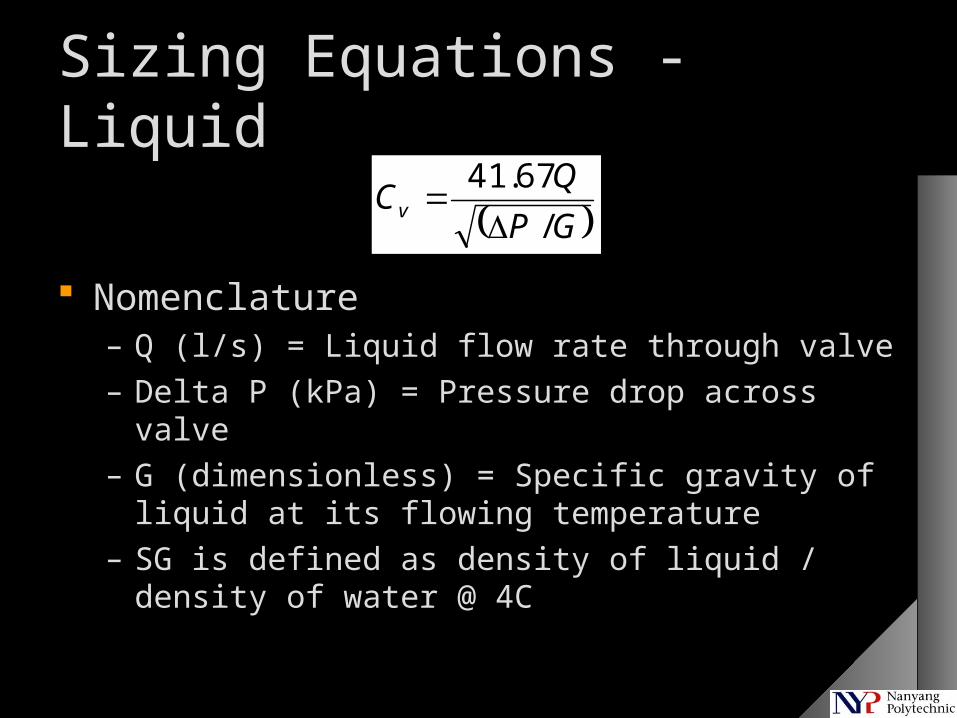
Nomenclature– Q (l/s) = Liquid flow rate through valve– Delta P (kPa) = Pressure drop across valve– G (dimensionless) = Specific gravity of liquid at its
flowing temperature– SG is defined as density of liquid / density of water @
4C
GP
QCv
/
67.41
Sizing Equations - Steam
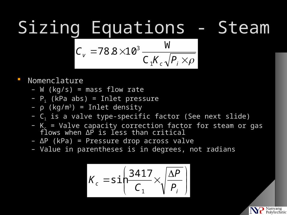
Nomenclature– W (kg/s) = mass flow rate– Pi (kPa abs) = Inlet pressure– ρ (kg/m3) = Inlet density– C1 is a valve type-specific factor (See next slide)– Kc = Valve capacity correction factor for steam or gas flows when ΔP is
less than critical– ΔP (kPa) = Pressure drop across valve– Value in parentheses is in degrees, not radians
ic
vPK
C1
3
C
W108.78
ic P
P
CK
1
3417sin
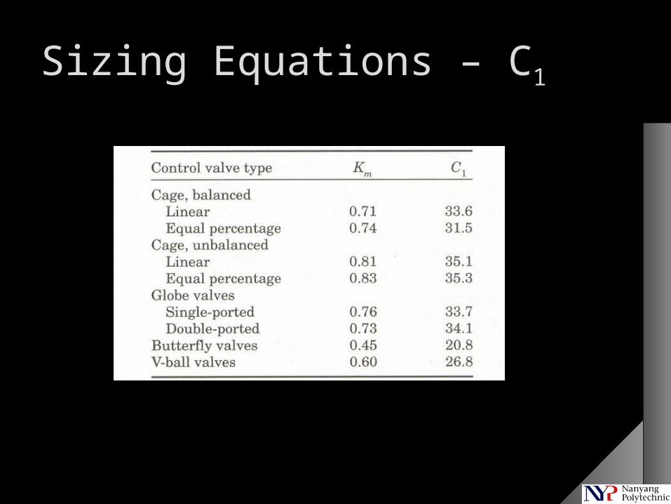
Sizing Equations – C1
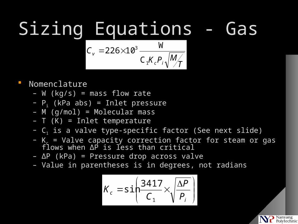
Sizing Equations - Gas
Nomenclature– W (kg/s) = mass flow rate– Pi (kPa abs) = Inlet pressure– M (g/mol) = Molecular mass– T (K) = Inlet temperature– C1 is a valve type-specific factor (See next slide)– Kc = Valve capacity correction factor for steam or gas flows when ΔP is
less than critical– ΔP (kPa) = Pressure drop across valve– Value in parentheses is in degrees, not radians
ic P
P
CK
1
3417sin
TMPK
Cic
v
1
3
C
W10226
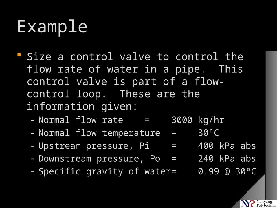
Example
Size a control valve to control the flow rate of water in a pipe. This control valve is part of a flow-control loop. These are the information given:– Normal flow rate = 3000 kg/hr– Normal flow temperature = 30ºC– Upstream pressure, Pi = 400 kPa abs– Downstream pressure, Po = 240 kPa abs– Specific gravity of water = 0.99 @ 30ºC
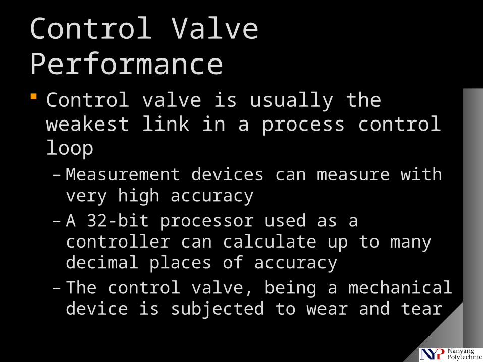
Control Valve Performance
Control valve is usually the weakest link in a process control loop– Measurement devices can measure with very
high accuracy– A 32-bit processor used as a controller can
calculate up to many decimal places of accuracy
– The control valve, being a mechanical device is subjected to wear and tear
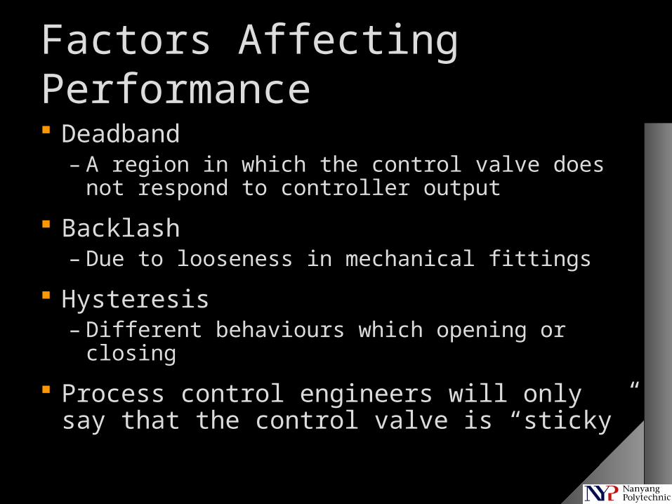
Factors Affecting Performance
Deadband– A region in which the control valve does not
respond to controller output
Backlash– Due to looseness in mechanical fittings
Hysteresis– Different behaviours which opening or closing
Process control engineers will only say that the control valve is “sticky”
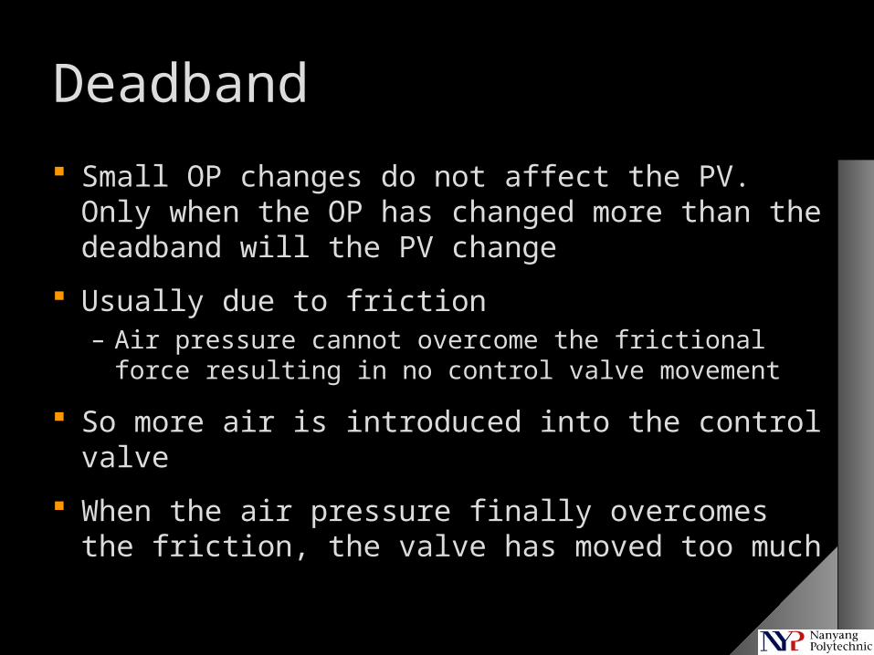
Deadband
Small OP changes do not affect the PV. Only when the OP has changed more than the deadband will the PV change
Usually due to friction– Air pressure cannot overcome the frictional force
resulting in no control valve movement
So more air is introduced into the control valve
When the air pressure finally overcomes the friction, the valve has moved too much
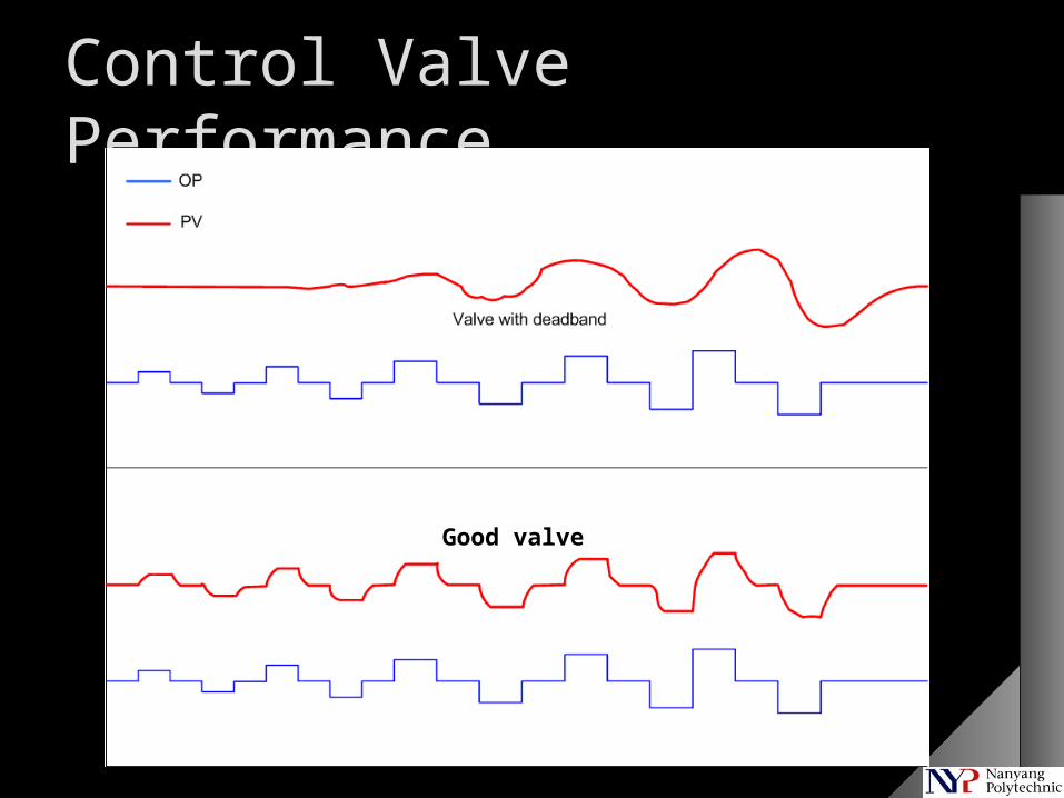
Control Valve Performance
Good valve
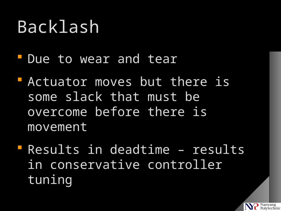
Backlash
Due to wear and tear
Actuator moves but there is some slack that must be overcome before there is movement
Results in deadtime – results in conservative controller tuning
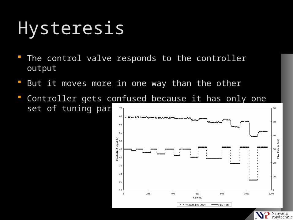
Hysteresis
The control valve responds to the controller output
But it moves more in one way than the other
Controller gets confused because it has only one set of tuning parameters
20
25
30
35
40
45
50
55
60
65
70
0 200 400 600 800 1000 1200
Time (s)
Co
ntr
olle
r O
utp
ut
(%)
0
10
20
30
40
50
60
Flo
w R
ate
(m3
/hr)
Controller Output Flow Rate
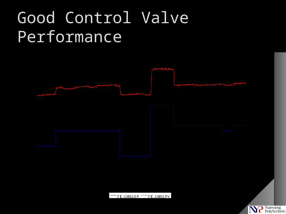
Good Control Valve Performance
11
11.5
12
12.5
13
13.5
14
14.5
15
15.5
16
0 500 1000 1500 2000 2500 3000 3500 4000
Co
ntr
oll
er O
utp
ut
(%)
0
5000
10000
15000
20000
25000
Flo
w (
Nm
3/h
r)
FIC-13052.OP FIC-13052.PV
Response even at 0.2% output change
FIC-13052 data with spikes removed.
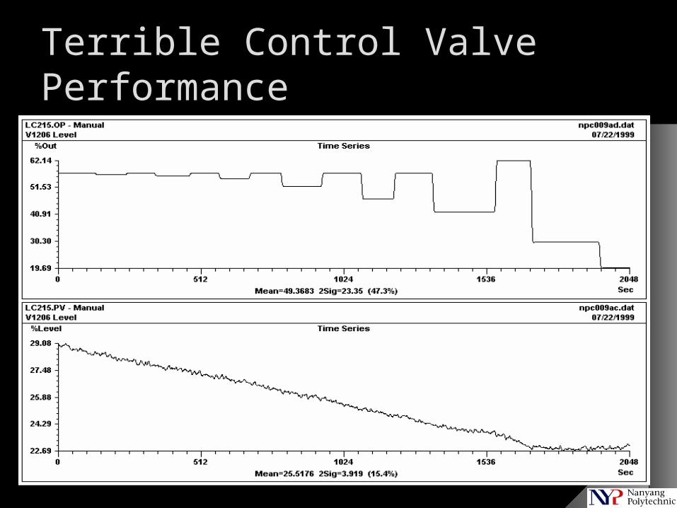
Terrible Control Valve Performance
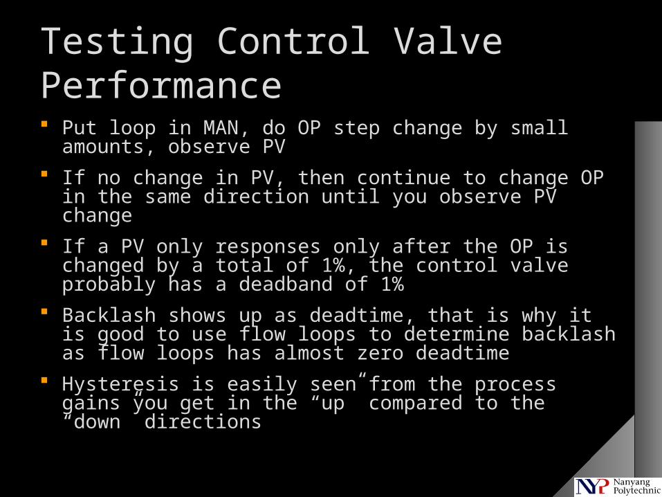
Testing Control Valve Performance
Put loop in MAN, do OP step change by small amounts, observe PV
If no change in PV, then continue to change OP in the same direction until you observe PV change
If a PV only responses only after the OP is changed by a total of 1%, the control valve probably has a deadband of 1%
Backlash shows up as deadtime, that is why it is good to use flow loops to determine backlash as flow loops has almost zero deadtime
Hysteresis is easily seen from the process gains you get in the “up” compared to the “down” directions
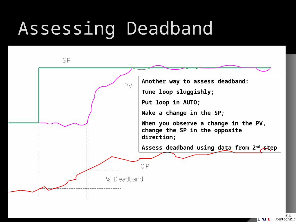
Assessing Deadband
SP
PV
OP
% Deadband
Another way to assess deadband:
Tune loop sluggishly;
Put loop in AUTO;
Make a change in the SP;
When you observe a change in the PV, change the SP in the opposite direction;
Assess deadband using data from 2nd step
Plant Testing