tools of the imagination
DESCRIPTION
The construction of a building is fascinating to watch, as the symbiosis between man and machine turns what seem to be scattered piles of material into architecture. But before the tools of construction ever arrive on the site, the architect wields a different set of tools to design, develop, and document the building-to-be. The history of these drawing tools is one of invention and innovation. In a profession increasingly dominated by the computer, earlier tools--from the compass to the helicograph, ellipsograph, and volutor; from perspective charts to slopes and batters; from Mylar to modeling clay--are beautiful artifacts of a bygone day. Along with historical objects, the National Building Museum has collected wooden models by Frank Gehry and hand-drawn sketches by Tod Williams, showing that the tools of the imagination are still very much a part of architectural design.TRANSCRIPT

Tools of the Imagination: Drawing Tools and Technologies from the Eighteenth Century to the Present
Susan C. Piedmont-Palladino, editor
PRINCETON ARCHITECTURAL PRESS, NEW YORK

viii Foreword Chase W. Rynd, Executive Director,
National Building Museum
x Preface Howard Decker, FAIA
1 Introduction Susan C. Piedmont-Palladino
7 Circles and Spheres
21 The Line
31 The Lead Pencil: Lever of the Architect’s Imagination Paul Emmons
41 The Geometry of Art
53 Light and Shadow
63 Perspective
73 Design Tools: A Collector’s Perspective and an Architect’s Odyssey
David V. Thompson, AIA
81 Copying
89 From Model to Drawing to Building
97 Erasing or Deleting
109 Imagination and Building Beyond Tools Phillip G. Bernstein, FAIA
117 Conclusion: Improvisations, Instruments, and Algorithms
William J. Mitchell
120 Bibliography and Additional Sources
122 Exhibition Acknowledgments
123 Image Credits
124 Contributor Biographies
Contents


Circles and Spheres
“A draw pen, and pencil leg, both made to slide into the leg of the
dividers occasionally. . . a pair of brass dividers with a movable center
for reducing drafts. . . I think they have been not long invented and
are under patent.” —Thomas Jefferson, ordering drawing tools from
England in 1786.
Contemporary architects have access to an extraordinary
array of tools, but their studios and workspaces are likely
to contain tools that would have been familiar to Thomas
Jefferson: triangles and compasses share desk space with
laptops and scanners. Because the rules of geometry are
unchanged, compasses remain useful, though architects
rarely exploit their full potential. The name of this familiar
two-legged drawing instrument originates from the Latin
word compassare (to pace off or to measure). Walking
across a drawing, the legs of the compass can pace a line,
locate a point, bisect an angle, and, of course, construct
a circle.
Compasses remain useful for drawing circles, but com-
plex curvilinear geometries require more complex tools.
Helicographs, ellipsographs, and volutors are just
some of the unique tools invented in the past to draw
specific curvilinear forms, such as cones, ellipses, and
spirals. Each of these drawing tasks arises or vanishes
with changing tastes and construction technologies.
The volutor, invented in 1857 by H. Johnson, illustrates one
of the constants of technological innovation, what historian
of technology Carl Mitcham calls “efforts to save effort.” The
classical revival of the eighteenth and nineteenth centuries
had brought the Ionic column capital back to the draw-
ing board. Previously, constructing a spiral, the underlying
geometry of the Ionic volute, had been accomplished using
a compass in a series of steps involving locating center
points and striking arcs in a specific sequence. It was ac-
curate, but hardly quick enough to serve the rising demand
for buildings in the nineteenth century. The effort to save
effort was the invention of the volutor, an elegant device
that allowed a smooth construction of a spiral, rather than
the sequence of discrete steps, described exhaustively in
William Salmon’s treatise Palladio Londonensis (1745). To
the modern reader, this litany of steps is almost as impen-
etrable as computer code, and it is fundamentally the same
thing: each is a set of instructions that, when
executed correctly, will result in a predictable outcome.
One can imagine the glee with which the younger generation
of classicists embraced the volutor as the older generation
mourned the loss of the knowledge of spiral construction.
The volutor was fated to a short life. No sooner had it been
developed that the entire culture of architecture, and
the manufacture of tools, changed forever. Classical archi-
tecture receded from fashion and the clean lines and pure
geometries of the modern movement returned drawing to
the fundamental tools.
Now, all of these problems and others are solved deep
inside the computer. The multitasking compass still paces,
measures, and constructs circles, whereas the computer
has teased these functions apart into different tasks. The
“draw circle” command no longer belongs to the same tool
set as measuring. The digital tool is a tool once removed
from the drawing problems. The code itself is the tool.

8 TOOLS OF THE IMAGINATION
left and below
Pillar folding compass(England), ca. 1850. Nickel-silver, steel; 41/4 x 15/8 x 3/4 in.
opposite
Monticello: ionic portico and dome, rectoThomas Jefferson, ca. 1778. Ink on paper, 715/16 x 615/16 in.


10 TOOLS OF THE IMAGINATION
PMS 877M

CIRCLES AND SPHERES 11
left
Monticello: drawing octagonsThomas Jefferson, 1771. Ink on paper, 45/16 x 43/8 in.
right
Monticello: curve of domeThomas Jefferson, ca. 1796. Ink on paper, 715/16 x 41/2 in.
opposite, top
Tubular compass in case (England), ca. 1890. Nickel-silver, steel, with Morrocan leather case; 153/4 x 31/2 x 11/8 in.
opposite, bottom
Beam compass(France), ca. 1790. Silver, steel, ebony; 93/4 x 2 x 1/2 in.
PMS 877M


CIRCLES AND SPHERES 13
opposite
Section of the RotundaThomas Jefferson, 1819. Pricking, iron-gall ink on laid paper engraved with coordinate lines; 83/4 x 83/4 in.
below
CompassesReprinted from George Adams, Geometrical and Graphical Essays, 3rd ed. (London: W. Glendinning, 1803), plate 1.
PMS 877M
14 TOOLS OF THE IMAGINATION
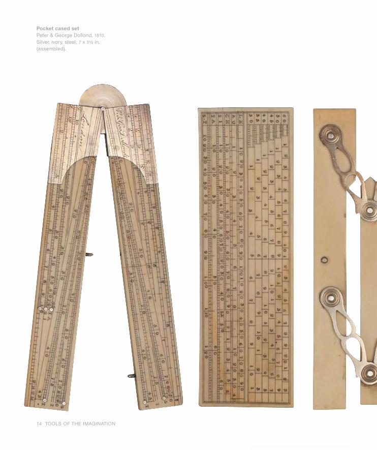
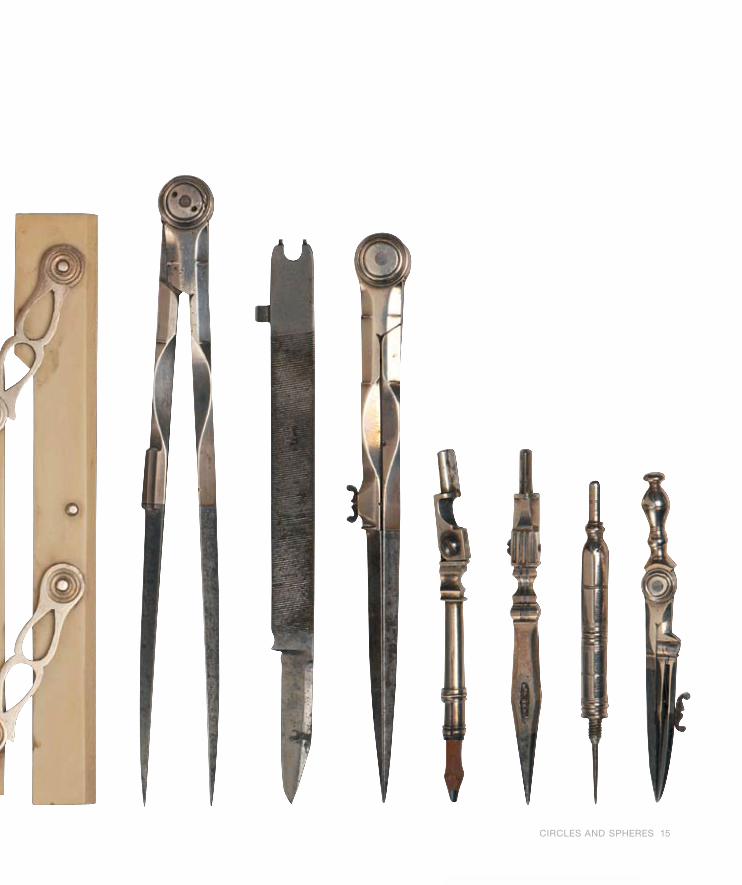
Pocket cased setPeter & George Dollond, 1810. Silver, ivory, steel; 7 x 31/2 in. (assembled).
PMS 877M
CIRCLES AND SPHERES 15
PMS 877M

16 TOOLS OF THE IMAGINATION
to the Arch last described, and continue the Arch-Line till it meets
the Perpendicular GH.
Thirdly, On the Point 3, place your Compasses and open them to
the Arch last described, and continue the Arch-Line till it meet the
Perpendicular EF. . .
In like manner you may turn it about till you have gone through all
twelve Centers, which will describe the contour of the Volute as re-
quired. The inside Line, or Border, is described by a second Draught,
in the same Manner as the former, only placing the fixed Foot of the
Compasses in the twelve other Centers, very near
the first, viz. at one fifth part of the Distance that is between the
former, reckoning towards the Center of the Eye; and these twelve
Centers are represented by the twelve Points in the Eye of the
Volute made larger that any other, on which the inside Line may be
described as required.”
Instruction for constructing an Ionik Volute with a compass, from
William Salmon’s Palladio Londinensis of 1745:
“First draw the Astragal AB, and though the Middle thereof the line
EF; then from the Top of the Abacus, let fall, perpendicular to the
former, another line passing through the Center of the Circle,
or Eye, of the Volute, as GH. Within this Circle are twelve Centers
marked 1, 2, 3, 4, & c. to 12, on which the Contour of the Volute is de-
scribed, and are thus to be found. Describe a Geometrical Square
whose Diagonals are one in the Horizontal Line, and the other in the
Perpendicular Line, crossing each other in the Center of the Eye;
from the Middle of the Sides of this Square draw two lines which di-
vide the Square into four, and each Line being divided into six Parts,
gives the twelve Centers, or Points, required as they are numbered
in the eye of the Volute. To describe the Volute, open your com-
passes from No. 1 (in the Eye of the Volute) to the intersection of the
Perpendicular and the lower part of the Abacus, and draw a Quarter
of a Circle, viz. Continue it till it meets the Horizontal Line EF.
Secondly, On the Point 2, place your Compasses, and open them
PMS 877M

opposite, left
The Ionick OrderReprinted from William Salmon, Palladio Londinensis (London: S. Birt, 1748), plate VI.
opposite, right
Diagram of a SpiralReprinted from William Salmon, Palladio Londinensis (London: S. Birt, 1748), plate XVII.
below
Volutorca. 1858. Brass, horn, porcelain, thread, steel; 8.5 x 30 x 19.5 cm (overall).
CIRCLES AND SPHERES 17
PMS 877M

18 TOOLS OF THE IMAGINATION
PMS 877M

CIRCLES AND SPHERES 19
opposite
Group Research SpacesRyan Chin and Jeffrey Tsui, from Library for the Information Age, 1998
left, top
Pod: The Digitally Mediated Reading Room for OneRyan Chin and Jeffrey Tsui, from Library for the Information Age, 1998
The Association for Computer Aided Design in Architecture
(ACADIA) launched its first design competition in 1998, challenging
architects to rethink a traditional building type—the library—with
nontraditional tools. For their winning solution, Ryan Chin, Jeffrey
Tsui, and Constance Lai, architecture students at the Massachu-
setts Institute of Technology, proposed a Library for One. Working
first in sketches and clay models, the team moved quickly into the
digital design environment, where they could wield the tools best
suited to represent a library for the information age. Chin envisions
a future where the architect would no longer hunch over a drawing
board or a screen but would be able to manipulate virtual objects.
Up to the elbows in virtual space, the architect could design like an
orchestra conductor, summoning materials and spaces to perform.
left, bottom
Pod InteriorRyan Chin and Jeffrey Tsui, from Library for the Information Age, 1998
PMS 877M
