tm access chamber system brochure (low res).pdfe. [email protected] welcome integrated...
TRANSCRIPT
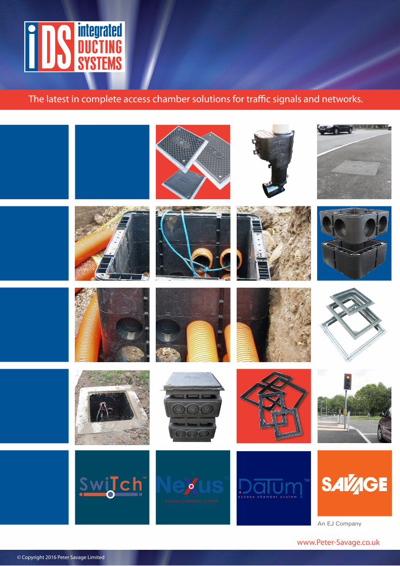
The latest in complete access chamber solutions for traffic signals and networks.
TM
access chamber system
© Copyright 2016 Peter Savage Limited
www.Peter-Savage.co.uk
An EJ Company
Peter Savage Limited operates a policy of continual development & reserves the right to alter specifications without notice. www.Peter-Savage.co.uk
Nuneaton T. 024 7664 1777 F. 024 7637 5250
Wakefield T. 01924 258 381 F. 01924 258 382
www.Peter-Savage.co.uk
WelcomeIntegrated Ducting Systems - IDS, a brand within Peter Savage Limited, represents a significant development in ducting system technologies, meeting the requirements of clients, designers and contractors within the civil engineering and construction industries. IDS is approved for use by local authorities nationwide and has been specified extensively in numerous traffic signal and cabling situations, from major motorway junctions to high street pedestrian crossings.
2
Savage Portfolio Products page 3
Nexus™ Structural Chambers page 4
Nexus™ Features & Specification Clause page 5
Nexus™ Chamber Installation Instructions page 6
Datum™ Chamber Systems page 7
Datum™ Benefits & Specification Clause page 8
Datum™ Chamber Installation Instructions page 9
Switch™ Pole Retention System page 10
IDS Covers Only- Anti-slip Composite Covers page 11
Ductile Iron Universal Frame - DUNF page 12
Galvanised Steel Universal Frame - UNF page 13
IDS Cover & Frames Complete Units page 14
IDS Cover & Frames Installation Instructions page 15
Axis™ Hinged Carriageway Covers page 16
IDS Case Studies page 17
Peter Savage Limited operates a policy of continual development & reserves the right to alter specifications without notice. www.Peter-Savage.co.uk
Nuneaton T. 024 7664 1777 F. 024 7637 5250
Wakefield T. 01924 258 381 F. 01924 258 382
www.Peter-Savage.co.uk
3
™
HIGH SECURITY ACCESS COVERS
™
Superior �nish aluminiun recessed access covers
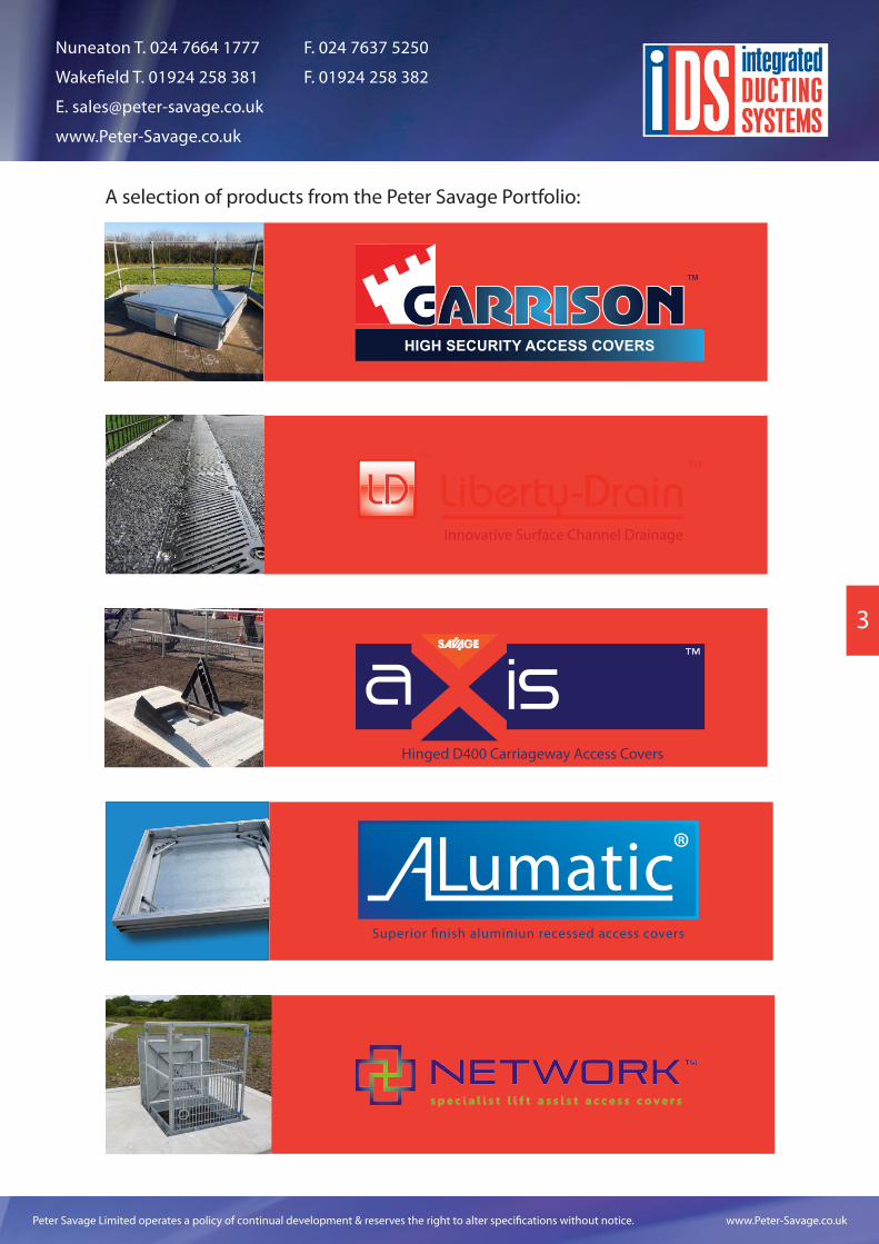
A selection of products from the Peter Savage Portfolio:
Innovative Surface Channel Drainage
Hinged D400 Carriageway Access Covers
™
Liberty-DrainLD™
Peter Savage Limited operates a policy of continual development & reserves the right to alter specifications without notice. www.Peter-Savage.co.uk
Nuneaton T. 024 7664 1777 F. 024 7637 5250
Wakefield T. 01924 258 381 F. 01924 258 382
www.Peter-Savage.co.uk
4
TM
access chamber system
TM
access chamber system
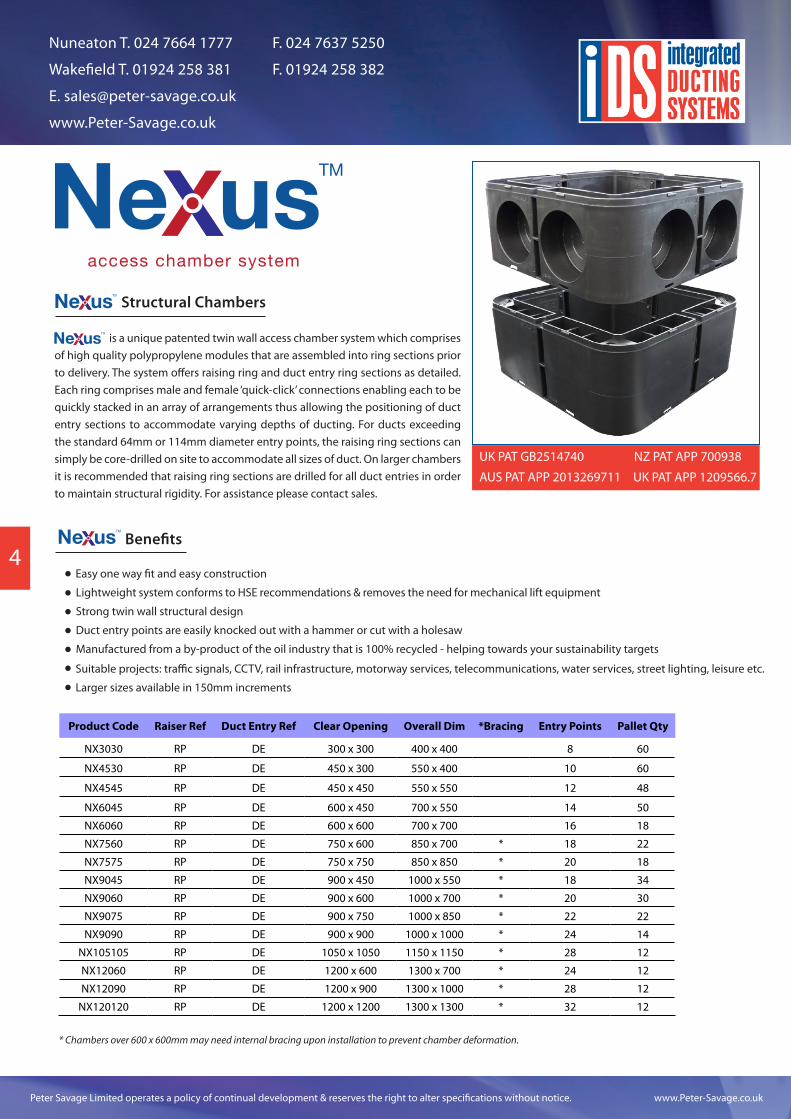
Structural Chambers
is a unique patented twin wall access chamber system which comprises of high quality polypropylene modules that are assembled into ring sections prior to delivery. The system offers raising ring and duct entry ring sections as detailed. Each ring comprises male and female ‘quick-click’ connections enabling each to be quickly stacked in an array of arrangements thus allowing the positioning of duct entry sections to accommodate varying depths of ducting. For ducts exceeding the standard 64mm or 114mm diameter entry points, the raising ring sections can simply be core-drilled on site to accommodate all sizes of duct. On larger chambers it is recommended that raising ring sections are drilled for all duct entries in order to maintain structural rigidity. For assistance please contact sales.
TM
access chamber system
Benefits
Easy one way fit and easy construction
Lightweight system conforms to HSE recommendations & removes the need for mechanical lift equipment
Strong twin wall structural design
Duct entry points are easily knocked out with a hammer or cut with a holesaw
Manufactured from a by-product of the oil industry that is 100% recycled - helping towards your sustainability targets
Suitable projects: traffic signals, CCTV, rail infrastructure, motorway services, telecommunications, water services, street lighting, leisure etc.
Larger sizes available in 150mm increments
TM
access chamber system
Product Code Raiser Ref Duct Entry Ref Clear Opening Overall Dim *Bracing Entry Points Pallet Qty
NX3030 RP DE 300 x 300 400 x 400 8 60
NX4530 RP DE 450 x 300 550 x 400 10 60
NX4545 RP DE 450 x 450 550 x 550 12 48
NX6045 RP DE 600 x 450 700 x 550 14 50
NX6060 RP DE 600 x 600 700 x 700 16 18
NX7560 RP DE 750 x 600 850 x 700 * 18 22
NX7575 RP DE 750 x 750 850 x 850 * 20 18
NX9045 RP DE 900 x 450 1000 x 550 * 18 34
NX9060 RP DE 900 x 600 1000 x 700 * 20 30
NX9075 RP DE 900 x 750 1000 x 850 * 22 22
NX9090 RP DE 900 x 900 1000 x 1000 * 24 14
NX105105 RP DE 1050 x 1050 1150 x 1150 * 28 12
NX12060 RP DE 1200 x 600 1300 x 700 * 24 12
NX12090 RP DE 1200 x 900 1300 x 1000 * 28 12
NX120120 RP DE 1200 x 1200 1300 x 1300 * 32 12
* Chambers over 600 x 600mm may need internal bracing upon installation to prevent chamber deformation.
UK PAT GB2514740
AUS PAT APP 2013269711
NZ PAT APP 700938
UK PAT APP 1209566.7
Peter Savage Limited operates a policy of continual development & reserves the right to alter specifications without notice. www.Peter-Savage.co.uk
Nuneaton T. 024 7664 1777 F. 024 7637 5250
Wakefield T. 01924 258 381 F. 01924 258 382
www.Peter-Savage.co.uk
5
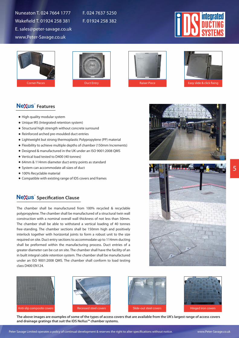
Corner Pieces Duct Entry Raiser Piece Easy slide & click fixing
Features
High quality modular system
Unique IRS (Integrated retention system)
Structural high strength without concrete surround
Reinforced arched pre-moulded duct entries
Lightweight but strong thermoplastic Polypropylene (PP) material
Flexibility to achieve multiple depths of chamber (150mm Increments)
Designed & manufactured in the UK under an ISO 9001:2008 QMS
TM
access chamber system
Vertical load tested to D400 (40 tonnes)
64mm & 114mm diameter duct entry points as standard
System can accommodate all sizes of duct
100% Recyclable materialCompatible with existing range of IDS covers and frames
Specification ClauseTM
access chamber system
The chamber shall be manufactured from 100% recycled & recyclable polypropylene. The chamber shall be manufactured of a structural twin wall construction with a nominal overall wall thickness of not less than 50mm. The chamber shall be able to withstand a vertical loading of 40 tonnes free-standing. The chamber sections shall be 150mm high and positively interlock together with horizontal joints to form a robust unit to the size required on site. Duct entry sections to accommodate up to 114mm ducting shall be preformed within the manufacturing process. Duct entries of a greater diameter can be cut on site. The chamber shall have the facility of an in built integral cable retention system. The chamber shall be manufactured under an ISO 9001:2008 QMS. The chamber shall conform to load testing class D400 EN124.
Anti-slip composite covers Recessed steel covers Slide-out steel covers Hinged iron covers
The above images are examples of some of the types of access covers that are available from the UK’s largest range of access covers and drainage gratings that suit the IDS NeXus™ chamber systems.
Peter Savage Limited operates a policy of continual development & reserves the right to alter specifications without notice. www.Peter-Savage.co.uk
Nuneaton T. 024 7664 1777 F. 024 7637 5250
Wakefield T. 01924 258 381 F. 01924 258 382
www.Peter-Savage.co.uk
6
TM
access chamber system
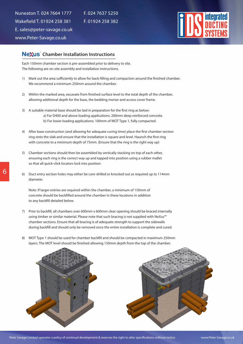
Chamber Installation Instructions
Mark out the area sufficiently to allow for back-filling and compaction around the finished chamber. We recommend a minimum 250mm around the chamber.
Within the marked area, excavate from finished surface level to the total depth of the chamber, allowing additional depth for the base, the bedding mortar and access cover frame.
A suitable material base should be laid in preparation for the first ring as below: a) For D400 and above loading applications: 200mm deep reinforced concrete. b) For lower loading applications: 100mm of MOT Type 1, fully compacted.
After base construction (and allowing for adequate curing time) place the first chamber sectionring onto the slab and ensure that the installation is square and level. Haunch the first ringwith concrete to a minimum depth of 75mm. (Ensure that the ring is the right way up)
Chamber sections should then be assembled by vertically stacking on top of each other, ensuring each ring is the correct way up and tapped into position using a rubber malletso that all quick-click locators lock into position.
Duct entry section holes may either be core-drilled or knocked out as required up to 114mmdiameter.
Note: If larger entries are required within the chamber, a minimum of 150mm of concrete should be backfilled around the chamber in these locations in additionto any backfill detailed below.
Prior to backfill, all chambers over 600mm x 600mm clear opening should be braced internallyusing timber or similar material. Please note that such bracing is not supplied with NeXus™chamber sections. Ensure that all bracing is of adequate strength to support the sidewallsduring backfill and should only be removed once the entire installation is complete and cured.
MOT Type 1 should be used for chamber backfill and should be compacted in maximum 250mmlayers. The MOT level should be finished allowing 150mm depth from the top of the chamber.
1)
2)
3)
4)
5)
6)
7)
8)
Each 150mm chamber section is pre-assembled prior to delivery to site.The following are on-site assembly and installation instructions.
Peter Savage Limited operates a policy of continual development & reserves the right to alter specifications without notice. www.Peter-Savage.co.uk
Nuneaton T. 024 7664 1777 F. 024 7637 5250
Wakefield T. 01924 258 381 F. 01924 258 382
www.Peter-Savage.co.uk
7
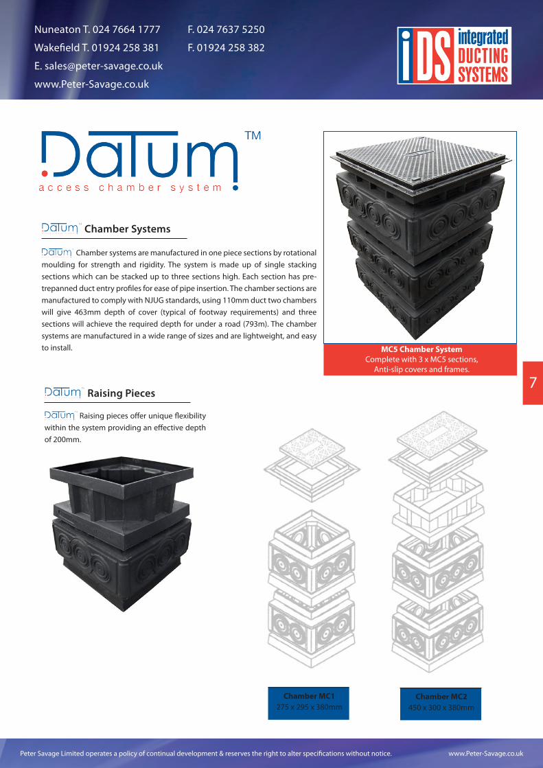
Chamber systems are manufactured in one piece sections by rotational moulding for strength and rigidity. The system is made up of single stacking sections which can be stacked up to three sections high. Each section has pre-trepanned duct entry profiles for ease of pipe insertion. The chamber sections are manufactured to comply with NJUG standards, using 110mm duct two chambers will give 463mm depth of cover (typical of footway requirements) and three sections will achieve the required depth for under a road (793m). The chamber systems are manufactured in a wide range of sizes and are lightweight, and easy to install.
Chamber Systems
Raising Pieces
Raising pieces offer unique flexibility within the system providing an effective depth of 200mm.
MC5 Chamber SystemComplete with 3 x MC5 sections,
Anti-slip covers and frames.
Chamber MC1275 x 295 x 380mm
Chamber MC2450 x 300 x 380mm
Peter Savage Limited operates a policy of continual development & reserves the right to alter specifications without notice. www.Peter-Savage.co.uk
Nuneaton T. 024 7664 1777 F. 024 7637 5250
Wakefield T. 01924 258 381 F. 01924 258 382
www.Peter-Savage.co.uk
8
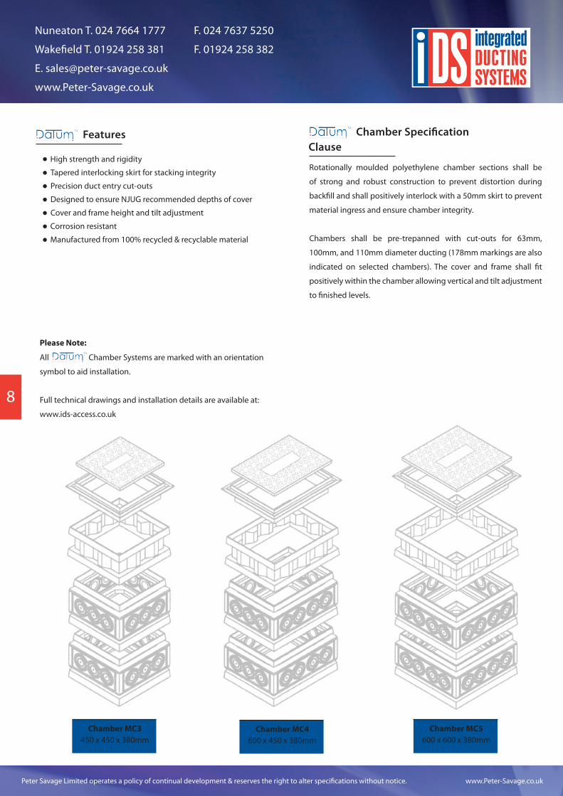
Chamber MC3450 x 450 x 380mm
Chamber MC4600 x 450 x 380mm
Chamber MC5600 x 600 x 380mm
Features
High strength and rigidity
Tapered interlocking skirt for stacking integrity
Precision duct entry cut-outs
Designed to ensure NJUG recommended depths of cover
Cover and frame height and tilt adjustment
Corrosion resistant
Chamber Specification Clause
Rotationally moulded polyethylene chamber sections shall be
of strong and robust construction to prevent distortion during
backfill and shall positively interlock with a 50mm skirt to prevent
material ingress and ensure chamber integrity.
Chambers shall be pre-trepanned with cut-outs for 63mm,
100mm, and 110mm diameter ducting (178mm markings are also
indicated on selected chambers). The cover and frame shall fit
positively within the chamber allowing vertical and tilt adjustment
to finished levels.
Please Note:
All Chamber Systems are marked with an orientation
symbol to aid installation.
Full technical drawings and installation details are available at:
www.ids-access.co.uk
Manufactured from 100% recycled & recyclable material
Peter Savage Limited operates a policy of continual development & reserves the right to alter specifications without notice. www.Peter-Savage.co.uk
Nuneaton T. 024 7664 1777 F. 024 7637 5250
Wakefield T. 01924 258 381 F. 01924 258 382
www.Peter-Savage.co.uk
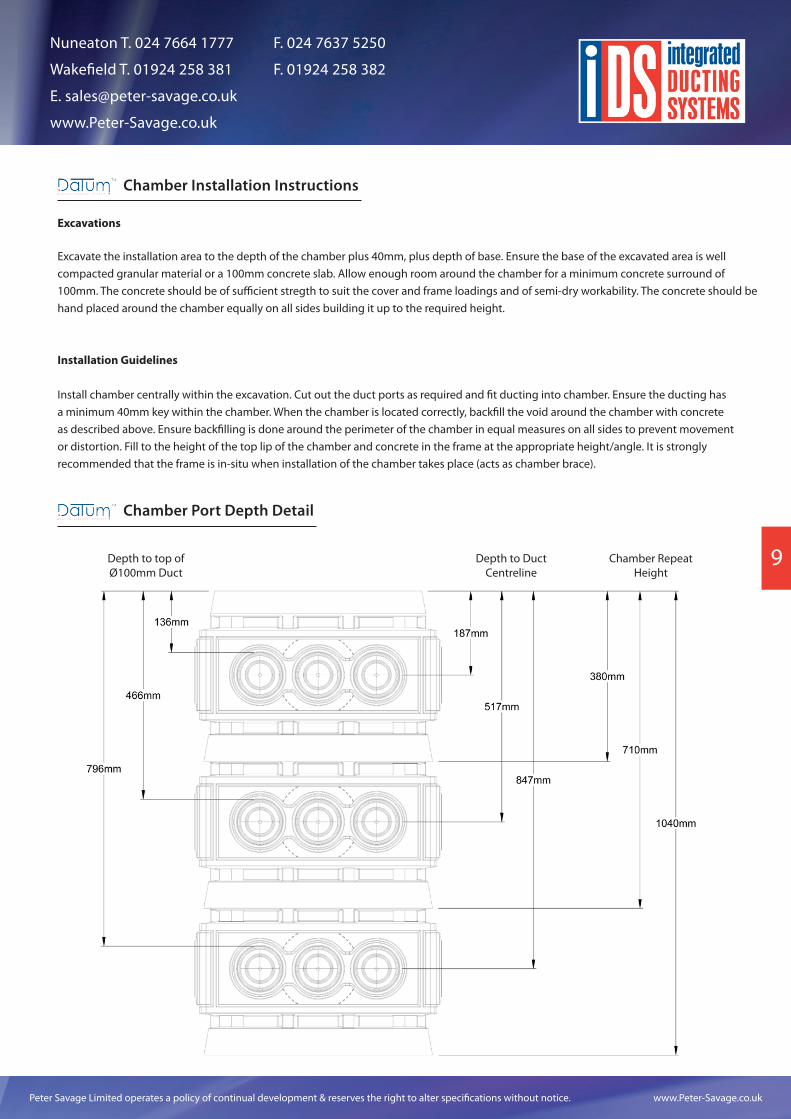
9Depth to top of Ø100mm Duct
Depth to Duct Centreline
Chamber Repeat Height
Chamber Installation Instructions
Excavations
Excavate the installation area to the depth of the chamber plus 40mm, plus depth of base. Ensure the base of the excavated area is well compacted granular material or a 100mm concrete slab. Allow enough room around the chamber for a minimum concrete surround of 100mm. The concrete should be of sufficient stregth to suit the cover and frame loadings and of semi-dry workability. The concrete should be hand placed around the chamber equally on all sides building it up to the required height.
Installation Guidelines
Install chamber centrally within the excavation. Cut out the duct ports as required and fit ducting into chamber. Ensure the ducting has a minimum 40mm key within the chamber. When the chamber is located correctly, backfill the void around the chamber with concrete as described above. Ensure backfilling is done around the perimeter of the chamber in equal measures on all sides to prevent movement or distortion. Fill to the height of the top lip of the chamber and concrete in the frame at the appropriate height/angle. It is strongly recommended that the frame is in-situ when installation of the chamber takes place (acts as chamber brace).
Chamber Port Depth Detail
Peter Savage Limited operates a policy of continual development & reserves the right to alter specifications without notice. www.Peter-Savage.co.uk
Nuneaton T. 024 7664 1777 F. 024 7637 5250
Wakefield T. 01924 258 381 F. 01924 258 382
www.Peter-Savage.co.uk
10
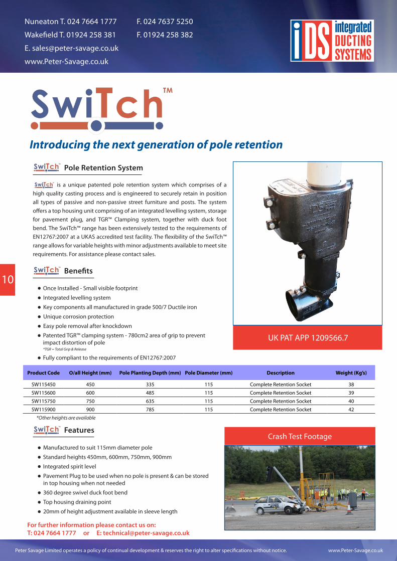
Introducing the next generation of pole retention
Benefits
Once Installed - Small visible footprint
Integrated levelling system
Key components all manufactured in grade 500/7 Ductile iron
Unique corrosion protection
Easy pole removal after knockdown
Patented TGR™ clamping system - 780cm2 area of grip to prevent impact distortion of pole*TGR = Total Grip & Release
UK PAT APP 1209566.7
Features
Integrated spirit level
Pavement Plug to be used when no pole is present & can be stored in top housing when not needed
360 degree swivel duck foot bend
Top housing draining point
Manufactured to suit 115mm diameter pole
Standard heights 450mm, 600mm, 750mm, 900mm
Pole Retention System
Fully compliant to the requirements of EN12767:2007
20mm of height adjustment available in sleeve length
Crash Test Footage
For further information please contact us on:T: 024 7664 1777 or E: [email protected]
*Other heights are available
is a unique patented pole retention system which comprises of a high quality casting process and is engineered to securely retain in position all types of passive and non-passive street furniture and posts. The system offers a top housing unit comprising of an integrated levelling system, storage for pavement plug, and TGR™ Clamping system, together with duck foot bend. The SwiTch™ range has been extensively tested to the requirements of EN12767:2007 at a UKAS accredited test facility. The flexibility of the SwiTch™ range allows for variable heights with minor adjustments available to meet site requirements. For assistance please contact sales.
Product Code O/all Height (mm) Pole Planting Depth (mm) Pole Diameter (mm) Description Weight (Kg’s)
SW115450 450 335 115 Complete Retention Socket 38
SW115600 600 485 115 Complete Retention Socket 39
SW115750 750 635 115 Complete Retention Socket 40
SW115900 900 785 115 Complete Retention Socket 42
Peter Savage Limited operates a policy of continual development & reserves the right to alter specifications without notice. www.Peter-Savage.co.uk
Nuneaton T. 024 7664 1777 F. 024 7637 5250
Wakefield T. 01924 258 381 F. 01924 258 382
www.Peter-Savage.co.uk
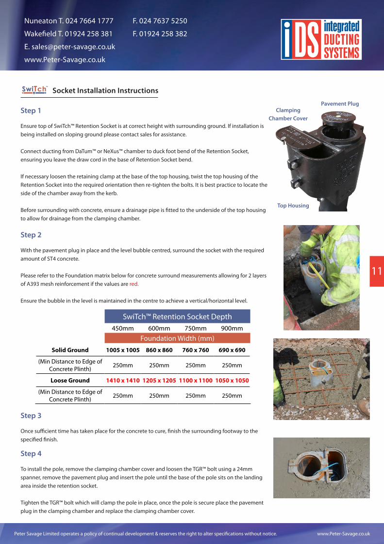
Socket Installation Instructions
Step 1
Ensure top of SwiTch™ Retention Socket is at correct height with surrounding ground. If installation is being installed on sloping ground please contact sales for assistance.
Connect ducting from DaTum™ or NeXus™ chamber to duck foot bend of the Retention Socket, ensuring you leave the draw cord in the base of Retention Socket bend.
If necessary loosen the retaining clamp at the base of the top housing, twist the top housing of the Retention Socket into the required orientation then re-tighten the bolts. It is best practice to locate the side of the chamber away from the kerb.
Before surrounding with concrete, ensure a drainage pipe is fitted to the underside of the top housing to allow for drainage from the clamping chamber.
Step 2
With the pavement plug in place and the level bubble centred, surround the socket with the required amount of ST4 concrete.
Please refer to the Foundation matrix below for concrete surround measurements allowing for 2 layers of A393 mesh reinforcement if the values are red.
Ensure the bubble in the level is maintained in the centre to achieve a vertical/horizontal level.
SwiTch™ Retention Socket Depth450mm 600mm 750mm 900mm
Foundation Width (mm)
Solid Ground 1005 x 1005 860 x 860 760 x 760 690 x 690
(Min Distance to Edge of Concrete Plinth) 250mm 250mm 250mm 250mm
Loose Ground 1410 x 1410 1205 x 1205 1100 x 1100 1050 x 1050
(Min Distance to Edge of Concrete Plinth) 250mm 250mm 250mm 250mm
Step 3
Once sufficient time has taken place for the concrete to cure, finish the surrounding footway to the specified finish.
Step 4
To install the pole, remove the clamping chamber cover and loosen the TGR™ bolt using a 24mm spanner, remove the pavement plug and insert the pole until the base of the pole sits on the landing area inside the retention socket.
Tighten the TGR™ bolt which will clamp the pole in place, once the pole is secure place the pavement plug in the clamping chamber and replace the clamping chamber cover.
Clamping Chamber Cover
Pavement Plug
Top Housing
11
Peter Savage Limited operates a policy of continual development & reserves the right to alter specifications without notice. www.Peter-Savage.co.uk
Nuneaton T. 024 7664 1777 F. 024 7637 5250
Wakefield T. 01924 258 381 F. 01924 258 382
www.Peter-Savage.co.uk
11
IDS Covers and Frames
The IDS system offers universal locking frames with the facility to accept
our full range of covers.
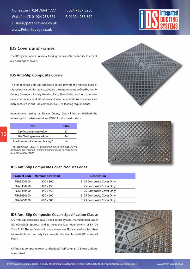
IDS Anti-Slip Composite Covers
The range of IDS anti-slip composite covers provide the highest levels of
slip resistance, comfortably exceeding the requirements defined by the UK
County Surveyors Society Working Party Data Collection Unit, to ensure
pedestrian safety in all situations and weather conditions. The covers are
manufactured in anti-slip composite to B125 loading requirements.
Independent testing by Devon County Council has established the
following skid resistance values (PSRV) for the tread surface.
Test PSRV
Dry Testing (mean value) 87
Wet Testing (mean value) 76
Equilibrium value for wet testing* 64
*The equilibrium value is determined when the wet PSRV’s achieved after repeated 1 minute polishing cycles have stabilised for 3 consecutive results
Product Code Nominal Size (mm) Description
PGAS300300 300 x 300 B125 Composite Cover Only
PGAS300450 300 x 450 B125 Composite Cover Only
PGAS450450 450 x 450 B125 Composite Cover Only
PGAS450600 450 x 600 B125 Composite Cover Only
PGAS600600 600 x 600 B125 Composite Cover Only
IDS Anti-Slip Composite Covers Specification ClauseIDS Anti-slip composite covers shall be IDS system, manufactured under
ISO 9001:2008 approval and to meet the load requirements of EN124
Class B125. The surface shall have a mean wet SRV value of not less than
76. Available with security lock down facility. Installed with IDS universal
frame.
All Anti-slip composite covers are badged ‘Traffic Signals’ & ‘Street Lighting’
as standard.
IDS Anti-Slip Composite Cover Product Codes
12
Peter Savage Limited operates a policy of continual development & reserves the right to alter specifications without notice. www.Peter-Savage.co.uk
Nuneaton T. 024 7664 1777 F. 024 7637 5250
Wakefield T. 01924 258 381 F. 01924 258 382
www.Peter-Savage.co.uk
11 12
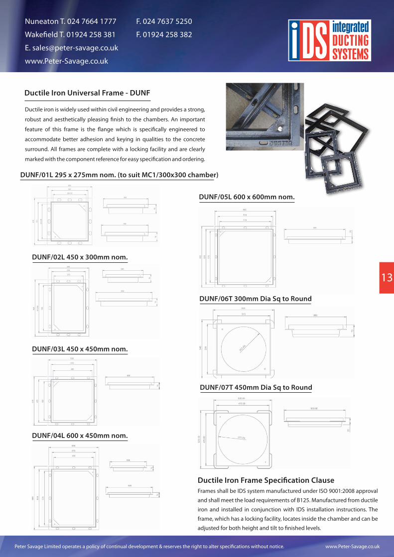
Ductile Iron Universal Frame - DUNF
Ductile iron is widely used within civil engineering and provides a strong,
robust and aesthetically pleasing finish to the chambers. An important
feature of this frame is the flange which is specifically engineered to
accommodate better adhesion and keying in qualities to the concrete
surround. All frames are complete with a locking facility and are clearly
marked with the component reference for easy specification and ordering.
DUNF/01L 295 x 275mm nom. (to suit MC1/300x300 chamber)
DUNF/02L 450 x 300mm nom.
DUNF/03L 450 x 450mm nom.
DUNF/04L 600 x 450mm nom.
DUNF/05L 600 x 600mm nom.
DUNF/06T 300mm Dia Sq to Round
DUNF/07T 450mm Dia Sq to Round
Ductile Iron Frame Specification ClauseFrames shall be IDS system manufactured under ISO 9001:2008 approval
and shall meet the load requirements of B125. Manufactured from ductile
iron and installed in conjunction with IDS installation instructions. The
frame, which has a locking facility, locates inside the chamber and can be
adjusted for both height and tilt to finished levels.
13
Peter Savage Limited operates a policy of continual development & reserves the right to alter specifications without notice. www.Peter-Savage.co.uk
Nuneaton T. 024 7664 1777 F. 024 7637 5250
Wakefield T. 01924 258 381 F. 01924 258 382
www.Peter-Savage.co.uk
13
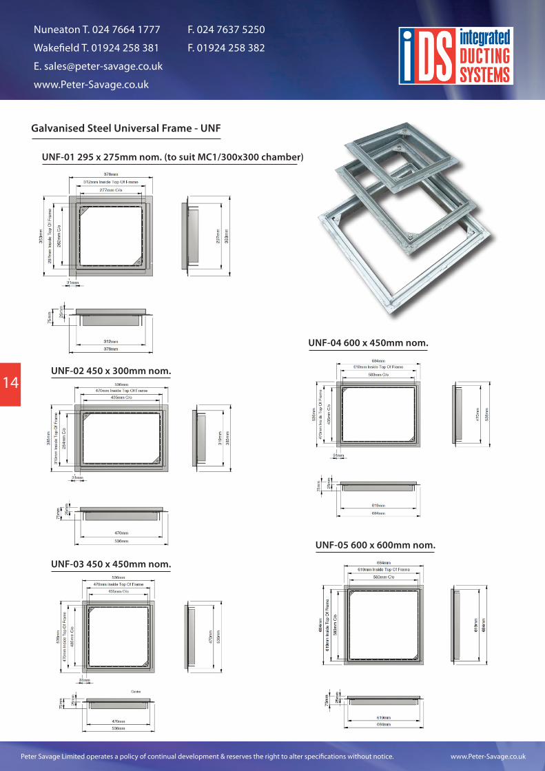
Galvanised Steel Universal Frame - UNF
UNF-01 295 x 275mm nom. (to suit MC1/300x300 chamber)
UNF-02 450 x 300mm nom.
UNF-03 450 x 450mm nom.
UNF-04 600 x 450mm nom.
UNF-05 600 x 600mm nom.
14
Peter Savage Limited operates a policy of continual development & reserves the right to alter specifications without notice. www.Peter-Savage.co.uk
Nuneaton T. 024 7664 1777 F. 024 7637 5250
Wakefield T. 01924 258 381 F. 01924 258 382
www.Peter-Savage.co.uk
13 14
Product Code Nominal Size (mm) Description
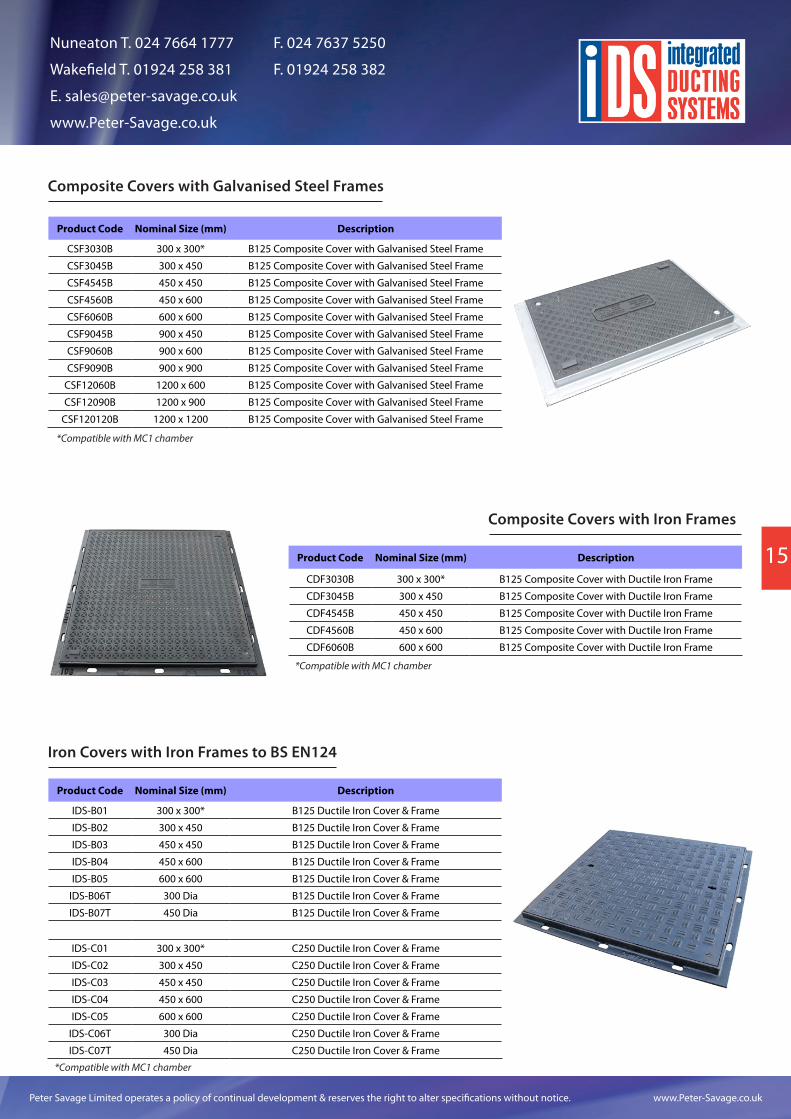
CSF3030B 300 x 300* B125 Composite Cover with Galvanised Steel Frame
CSF3045B 300 x 450 B125 Composite Cover with Galvanised Steel Frame
CSF4545B 450 x 450 B125 Composite Cover with Galvanised Steel Frame
CSF4560B 450 x 600 B125 Composite Cover with Galvanised Steel Frame
CSF6060B 600 x 600 B125 Composite Cover with Galvanised Steel Frame
CSF9045B 900 x 450 B125 Composite Cover with Galvanised Steel Frame
CSF9060B 900 x 600 B125 Composite Cover with Galvanised Steel Frame
CSF9090B 900 x 900 B125 Composite Cover with Galvanised Steel Frame
CSF12060B 1200 x 600 B125 Composite Cover with Galvanised Steel Frame
CSF12090B 1200 x 900 B125 Composite Cover with Galvanised Steel Frame
CSF120120B 1200 x 1200 B125 Composite Cover with Galvanised Steel Frame
Product Code Nominal Size (mm) Description
CDF3030B 300 x 300* B125 Composite Cover with Ductile Iron Frame
CDF3045B 300 x 450 B125 Composite Cover with Ductile Iron Frame
CDF4545B 450 x 450 B125 Composite Cover with Ductile Iron Frame
CDF4560B 450 x 600 B125 Composite Cover with Ductile Iron Frame
CDF6060B 600 x 600 B125 Composite Cover with Ductile Iron Frame
Product Code Nominal Size (mm) Description
IDS-B01 300 x 300* B125 Ductile Iron Cover & Frame
IDS-B02 300 x 450 B125 Ductile Iron Cover & Frame
IDS-B03 450 x 450 B125 Ductile Iron Cover & Frame
IDS-B04 450 x 600 B125 Ductile Iron Cover & Frame
IDS-B05 600 x 600 B125 Ductile Iron Cover & Frame
IDS-B06T 300 Dia B125 Ductile Iron Cover & Frame
IDS-B07T 450 Dia B125 Ductile Iron Cover & Frame
IDS-C01 300 x 300* C250 Ductile Iron Cover & Frame
IDS-C02 300 x 450 C250 Ductile Iron Cover & Frame
IDS-C03 450 x 450 C250 Ductile Iron Cover & Frame
IDS-C04 450 x 600 C250 Ductile Iron Cover & Frame
IDS-C05 600 x 600 C250 Ductile Iron Cover & Frame
IDS-C06T 300 Dia C250 Ductile Iron Cover & Frame
IDS-C07T 450 Dia C250 Ductile Iron Cover & Frame
Composite Covers with Galvanised Steel Frames
Composite Covers with Iron Frames
Iron Covers with Iron Frames to BS EN124
*Compatible with MC1 chamber
*Compatible with MC1 chamber
*Compatible with MC1 chamber
15
Peter Savage Limited operates a policy of continual development & reserves the right to alter specifications without notice. www.Peter-Savage.co.uk
Nuneaton T. 024 7664 1777 F. 024 7637 5250
Wakefield T. 01924 258 381 F. 01924 258 382
www.Peter-Savage.co.uk
15
Single Span Iron, Composite or Steel Access Covers and Frames Installation Instructions
Once the chamber sections have been built to the required depth, backfilling using MOT Type 1 stone should be completed according to section 8 on page 6. The MOT level should be finished allowing 150mm depth from the top of the chamber.
The remaining 150mm depth should be backfilled with C40 concrete and allowed sufficient cure time to achieve compressive strength.
Suitable bedding material (see below) should then be laid onto the top of the chamber ensuring that all voids in the chamber wall are filled with material to provide a solid base.
1)
2)
3)
a) For B125 loading covers, a general purpose bedding mortar such as Ultracrete M60 should be used for securing the frame to the chamber.
b) For higher load classes, frames should be bedded onto a high strength, rapid set mortar such as Ultracrete Envirobed or PY4. For traffic applications, frames should then be backfilled with a minimum of 300mm width of high strength flowable mortar such as Ultracrete QC10F.
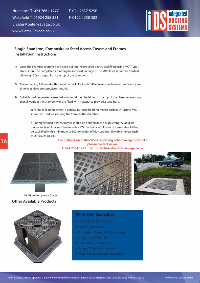
Other Available Products
KB1D-IDS (Loop Box)
150 x 150mm Clear Opening
150mm Deep Frame
Ductile Iron Grade 500/7 for improved
strength to weight ratio
Grade A to BS 5834 part 2
Badged ‘TS Loop’ as standard
Frame has slots for cable loop access
Multiple Composite Cover
For installation instructions regarding other Savage products please contact us on:
T: 024 7664 1777 or E: [email protected]
16
Peter Savage Limited operates a policy of continual development & reserves the right to alter specifications without notice. www.Peter-Savage.co.uk
Nuneaton T. 024 7664 1777 F. 024 7637 5250
Wakefield T. 01924 258 381 F. 01924 258 382
www.Peter-Savage.co.uk
15 16
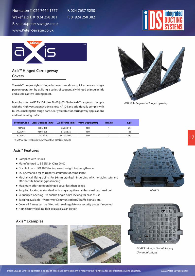
Axis™ Hinged Carriageway Covers
™
The Axis™ unique style of hinged access cover allows quick access and single person operation by utilising a series of sequentially hinged triangular lids and a sole captive locking point.
Manufactured to BS EN124 class D400 (400kN) the Axis™ range also comply with the Highways Agency advice note HA104 and additionally comply with BS 7903 making the range particularly suitable for carriageway applications and fast moving traffic.
Product Code Clear Opening (mm) O/all Frame (mm) Frame Depth (mm) Tri Lids Kg’s
KDAX9 600 x 450 760 x 610 100 1 75
KDAX14 750 x 675 910 x 835 100 1 125
KDAX13 1310 x 850 1470 x 1010 100 2 250
*Further sizes available please contact sales for details
Axis™ Features
Complies with HA104
Manufactured to BS EN124 Class D400
BSI Kitemarked for third party assurance of compliance
Mechanical lifting points for 36mm cranked hinge pins which enables safe and efficient site handling/positioning
Maximum effort to open hinged cover less than 25kg’s
Supplied locking as standard with single captive stainless steel cap head bolt
Sequenced opening - to enable single point locking for ease of use
Ductile Iron to ISO 1083 for improved weight to strength ratio
Badging available - ‘Motorway Communications’, ‘Traffic Signals’ etc.
Covers & frames can be fitted with sealing plates or security plates if required
High security locking bolt available as an option
Axis™ Examples
KDAX13 - Sequential hinged opening
KDAX9 - Badged for Motorway Communications
KDAX14
17
Peter Savage Limited operates a policy of continual development & reserves the right to alter specifications without notice. www.Peter-Savage.co.uk
Nuneaton T. 024 7664 1777 F. 024 7637 5250
Wakefield T. 01924 258 381 F. 01924 258 382
www.Peter-Savage.co.uk
17
Case Studies
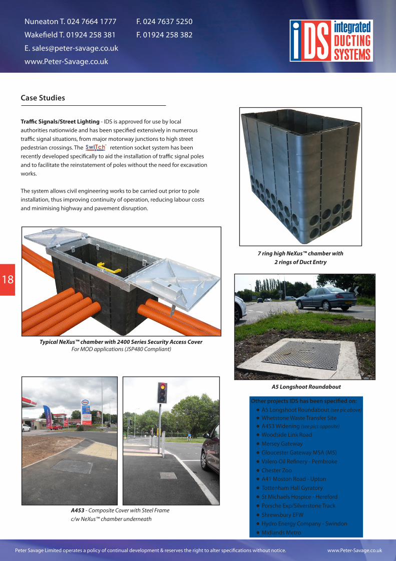
Traffic Signals/Street Lighting - IDS is approved for use by local authorities nationwide and has been specified extensively in numerous traffic signal situations, from major motorway junctions to high street pedestrian crossings. The retention socket system has been recently developed specifically to aid the installation of traffic signal poles and to facilitate the reinstatement of poles without the need for excavation works.
The system allows civil engineering works to be carried out prior to pole installation, thus improving continuity of operation, reducing labour costs and minimising highway and pavement disruption.
A453 - Composite Cover with Steel Frame c/w NeXus™ chamber underneath
Typical NeXus™ chamber with 2400 Series Security Access CoverFor MOD applications (JSP480 Compliant)
A5 Longshoot Roundabout
7 ring high NeXus™ chamber with 2 rings of Duct Entry
Other projects IDS has been specified on:A5 Longshoot Roundabout (see pic above)
Whetstone Waste Transfer SiteA453 Widening (see pics opposite)
Gloucester Gateway MSA (M5)Valero Oil Refinery - PembrokeChester Zoo
Woodside Link RoadMersey Gateway
A41 Moston Road - UptonTottenham Hall GyratorySt Michaels Hospice - HerefordPorsche Exp/Silverstone Track
Shrewsbury EFWHydro Energy Company - SwindonMidlands Metro
18
Peter Savage Limited operates a policy of continual development & reserves the right to alter specifications without notice. www.Peter-Savage.co.uk
Nuneaton T. 024 7664 1777 F. 024 7637 5250
Wakefield T. 01924 258 381 F. 01924 258 382
www.Peter-Savage.co.uk
17
Notes
19

Nuneaton T. 024 7664 1777 F. 024 7637 5250
Wakefield T. 01924 258 381 F. 01924 258 382
www.Peter-Savage.co.uk
Peter Savage Limited operates a policy of continual development & reserves the right to alter specifications without notice. www.Peter-Savage.co.uk
iDS is now part of...
Peter Savage LimitedHead OfficeLiberty HouseLiberty WayNuneatonWarwickshireCV11 6RZ
T. 024 7664 1777 F. 024 7637 5250
Peter Savage LimitedNorthern DepotYork HouseSandal Castle CentreAsdale RoadWakefieldWF2 7JE
T. 01924 258 381 F. 01924 258 382
Email: [email protected]
Peter Savage Limited operates a policy of continual development & reserves the right to alter specifications without notice.
www.facebook.com/PeterSavageLtd
@PeterSavageLtd
+Peter-Savageuk
petersavageltd