ti32, tir32, ti29, tir29, ti27, tir27 - fluke...
TRANSCRIPT
PN 3433221 July 2009, Rev.1, 5/11 © 2009-2011 Fluke Corporation. All rights reserved. Printed in USA. Specifications are subject to change without notice. All product names are trademarks of their respective companies. Software for this product is based in part on the work of the Independent JPEG Group.
Ti32, TiR32, Ti29, TiR29, Ti27, TiR27
Thermal Imagers
Users Manual

LIMITED WARRANTY AND LIMITATION OF LIABILITY
Each Fluke product is warranted to be free from defects in material and workmanship under normal use and service. The warranty period is two years and begins on the date of shipment. Parts, product repairs, and services are warranted for 90 days. This warranty extends only to the original buyer or end-user customer of a Fluke authorized reseller, and does not apply to fuses, disposable batteries, or to any product which, in Fluke's opinion, has been misused, altered, neglected, contaminated, or damaged by accident or abnormal conditions of operation or handling. Fluke warrants that software will operate substantially in accordance with its functional specifications for 90 days and that it has been properly recorded on non-defective media. Fluke does not warrant that software will be error free or operate without interruption.
Fluke authorized resellers shall extend this warranty on new and unused products to end-user customers only but have no authority to extend a greater or different warranty on behalf of Fluke. Warranty support is available only if product is purchased through a Fluke authorized sales outlet or Buyer has paid the applicable international price. Fluke reserves the right to invoice Buyer for importation costs of repair/replacement parts when product purchased in one country is submitted for repair in another country.
Fluke's warranty obligation is limited, at Fluke's option, to refund of the purchase price, free of charge repair, or replacement of a defective product which is returned to a Fluke authorized service center within the warranty period.
To obtain warranty service, contact your nearest Fluke authorized service center to obtain return authorization information, then send the product to that service center, with a description of the difficulty, postage and insurance prepaid (FOB Destination). Fluke assumes no risk for damage in transit. Following warranty repair, the product will be returned to Buyer, transportation prepaid (FOB Destination). If Fluke determines that failure was caused by neglect, misuse, contamination, alteration, accident, or abnormal condition of operation or handling, including overvoltage failures caused by use outside the product’s specified rating, or normal wear and tear of mechanical components, Fluke will provide an estimate of repair costs and obtain authorization before commencing the work. Following repair, the product will be returned to the Buyer transportation prepaid and the Buyer will be billed for the repair and return transportation charges (FOB Shipping Point).
THIS WARRANTY IS BUYER'S SOLE AND EXCLUSIVE REMEDY AND IS IN LIEU OF ALL OTHER WARRANTIES, EXPRESS OR IMPLIED, INCLUDING BUT NOT LIMITED TO ANY IMPLIED WARRANTY OF MERCHANTABILITY OR FITNESS FOR A PARTICULAR PURPOSE. FLUKE SHALL NOT BE LIABLE FOR ANY SPECIAL, INDIRECT, INCIDENTAL OR CONSEQUENTIAL DAMAGES OR LOSSES, INCLUDING LOSS OF DATA, ARISING FROM ANY CAUSE OR THEORY.
Since some countries or states do not allow limitation of the term of an implied warranty, or exclusion or limitation of incidental or consequential damages, the limitations and exclusions of this warranty may not apply to every buyer. If any provision of this Warranty is held invalid or unenforceable by a court or other decision-maker of competent jurisdiction, such holding will not affect the validity or enforceability of any other provision.
Fluke Corporation P.O. Box 9090 Everett, WA 98206-9090 U.S.A.
Fluke Europe B.V. P.O. Box 1186 5602 BD Eindhoven The Netherlands
11/99
To register your product online, visit http://register.fluke.com.
i
Table of Contents
Title Page
Introduction ............................................................................... 1 How to Contact Fluke................................................................ 2 Safety Information ..................................................................... 2 Unpacking the Imager................................................................ 3 Charging the Battery.................................................................. 4
Two-Bay Charging Base ........................................................ 4 On-Imager AC Power Socket................................................. 5 Optional 12 V Vehicle Charger.............................................. 5
Turning the Imager On and Off ................................................. 5 Features and Controls ................................................................ 6 Using the Menu.......................................................................... 7
Menu Escape/Live View ........................................................ 8 Basic User Preference Settings .............................................. 8
Changing the Displayed Language..................................... 8 Setting the Date .................................................................. 9 Setting the Time ................................................................. 9 Changing the Temperature Units........................................ 10 Using the Centerbox Feature .............................................. 10 Setting File Format ............................................................. 11 Setting the Backlight .......................................................... 12 Setting the Display Information Settings............................ 12
How to Install and Use Optional Lenses (Telephoto and Wide-Angle) .............................................................................. 13 Focusing and Capturing an Image ............................................. 17 Saving Imager Data ................................................................... 17 Adjusting the Thermal Image .................................................... 18
Selecting a Standard Palette ................................................... 18 Selecting an Ultra Contrast Palette...................................... 19 Setting the Range ................................................................... 19
Fast Auto/Manual Range Toggle........................................ 20 Fast Auto Rescale ............................................................... 20
Setting the Level (Manual)..................................................... 20
Ti32, TiR32, Ti29, TiR29, Ti27, TiR27 Users Manual
ii
Setting the Temperature Span (Manual) ................................. 21 Setting IR-Fusion and PIP.......................................................... 22 Reviewing and Deleting Stored Images ..................................... 22 Adding Voice Annotation to Saved Data ................................... 23 Listening to Voice Annotations.................................................. 24 Enabling/Disabling Spot Indicators............................................ 24 Making Accurate Temperature Measurements .......................... 24 Setting Emissivity ...................................................................... 25 Setting Reflected Background Temperature .............................. 26 Setting Transmission Correction................................................ 27 Setting Temperature Alarms ...................................................... 27
High Temperature Alarm (Ti32, Ti29, Ti27).......................... 28 Dewpoint Alarm (TiR32, TiR29, TiR27) ............................... 28
SmartView Software .................................................................. 28 Changing the SD Memory Card................................................. 29 Maintenance ............................................................................... 30
Cleaning the Imager................................................................ 30 Cleaning the Infrared Lens ..................................................... 30 Battery Care............................................................................ 31
General Specifications ............................................................... 32 Detailed Specifications............................................................... 33
iii
List of Tables
Table Title Page
1. Symbols ..................................................................................... 3 2. Accessories ................................................................................ 4 3. Features and Controls ................................................................ 6
List of Figures
Figure Title Page
1. Attachment and Removal of Optional Lenses ........................... 15 2. Range and Span Settings............................................................ 21 3. SD Memory Card Insertion........................................................ 29

Ti32, TiR32, Ti29, TiR29, Ti27, TiR27 Users Manual
iv

1
Introduction The Fluke Ti32, TiR32, Ti29, TiR29, Ti27, and TiR27 Thermal Imagers (hereafter “the Imager”) are handheld thermal imagers used for preventive and predictive maintenance, equipment troubleshooting, repair verification, building inspections, restoration and remediation work, energy audits, and weatherization purposes. The Ti32, Ti29, and Ti27 are optimized for industrial and commercial equipment maintenance, and the TiR32, TiR29, and TiR27 optimized for building envelope inspections and building diagnostics.
The temperature measurement range starts at -20 °C, and goes up to +600 °C for the Ti32, Ti29, and Ti27, and starts at -20 °C and goes up to +150 °C for the TiR32, TiR29, and TiR27. The thermal image can be displayed using any one of a number of standard color palettes or Ultra Contrast™ color palettes.
All models have IR-Fusion® technology, only available from Fluke, where a full visual image (640 X 480) can be displayed, blended, and stored with each IR image. Thermal and visual images can be presented simultaneously as a full thermal image or as a Picture-In-Picture (PIP) image in various blend modes.
Thermal and visual images are displayed on the Imager LCD and can be saved to a removable SD memory card. Transferring images to a PC is accomplished by removing the SD memory card and connecting it to a PC through the included, multi-format USB card reader. SmartView® software is included for image analysis and report generation from these saved images.
Imager power is supplied by one of two included, field-swappable, rechargeable Lithium-ion smart battery packs, with 4+ hours of continuous operation each.
In addition to the features mentioned above, the Imagers provide voice recording capabilities for annotating saved images, emissivity correction, reflected background temperature compensation, transmission correction, and many other useful, easy-to-use features.
Ti32, TiR32, Ti29, TiR29, Ti27, TiR27 Users Manual
2
How to Contact Fluke To contact Fluke, call one of the following telephone numbers:
• USA: 1-800-760-4523
• Canada: 1-800-36-FLUKE (1-800-363-5853)
• Europe: +31 402-675-200
• Japan: +81-3-3434-0181
• Singapore: +65-738-5655
• Anywhere in the world: +1-425-446-5500
Or, visit Fluke's website at www.fluke.com.
To register your product, visit http://register.fluke.com.
To view, print, or download the latest manual supplement, visit http://us.fluke.com/usen/support/manuals.
Safety Information Use the Imager only as specified in this manual. See Table 1 for a list of symbols used on the Imager and in this manual.
A Warning identifies hazardous conditions and actions that could cause bodily harm or death.
A Caution identifies conditions and actions that could damage the Imager or cause permanent loss of data.
Warning To prevent personal injury:
• See emissivity information for actual temperatures. Reflective objects result in lower than actual temperature measurements. These objects pose a burn hazard.
• Use the product only as specified, or the protection supplied by the product can be compromised.
• Batteries contain hazardous chemicals that can cause burns or explode. If exposure to chemicals occurs, clean with water and get medical aid.
• Follow all battery care and charging instructions in this manual.
Thermal Imagers Unpacking the Imager
3
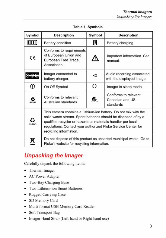
Table 1. Symbols
Symbol Description Symbol Description
Battery condition. Battery charging.
Conforms to requirementsof European Union and European Free Trade Association.
Important information. See manual.
Imager connected to battery charger.
Audio recording associated with the displayed image.
On Off Symbol Imager in sleep mode.
Conforms to relevant Australian standards.
Conforms to relevant Canadian and US standards
This camera contains a Lithium-ion battery. Do not mix with the solid waste stream. Spent batteries should be disposed of by a qualified recycler or hazardous materials handler per local regulations. Contact your authorized Fluke Service Center for recycling information.
Do not dispose of this product as unsorted municipal waste. Go to Fluke's website for recycling information.
Unpacking the Imager Carefully unpack the following items:
• Thermal Imager
• AC Power Adapter
• Two-Bay Charging Base
• Two Lithium-ion Smart Batteries
• Rugged Carrying Case
• SD Memory Card
• Multi-format USB Memory Card Reader
• Soft Transport Bag
• Imager Hand Strap (Left-hand or Right-hand use)
Ti32, TiR32, Ti29, TiR29, Ti27, TiR27 Users Manual
4
• User Manual (in various languages)
• SmartView® Software
• Warranty Registration Card
Note
Fluke recommends the use of the supplied SD memory card with the Imager. Fluke does not warrant the use or reliability of aftermarket SD memory cards of different brands or capacities.
See Table 2 for a list of accessories that are available for the Imager.
Table 2. Accessories
Model Description PN
FLK-TI-LENS/WIDE1 Wide Angle Infrared Lens 3441183
FLK-TI-LENS/TELE1 Telephoto Infrared Lens 3441176
FLK-TI-SBP3 Smart Battery Pack 3440365
FLK-TI-SBC3 Charging Base/Power Supply with Adapters
3440352
TI-CAR CHARGER 12 V Vehicle Charger Adapter 3039779
Charging the Battery Before using the Imager for the first time, charge the batteries in the included two-bay charging base for at least two and one-half hours. The charging status of each battery will be shown on the five-segment battery charge indicator on each battery.
Note
New batteries are not fully charged. Two to ten normal charging/discharging cycles may be required before the battery charges to its maximum capacity.
To charge the Imager’s battery, select one of the options that follow:
Two-Bay Charging Base
1. Plug the ac power supply into an ac wall outlet and connect dc output to charging base.
2. Insert one or two smart batteries into bays of charging base.
3. Charge batteries until charge indicators show “full”.
Thermal Imagers Turning the Imager On and Off
5
4. Remove smart batteries and unplug power supply when batteries are fully charged.
On-Imager AC Power Socket
1. Plug the ac power supply into an ac wall outlet and connect dc output to the Imager’s ac power socket.
2. Charge until on-screen indicator shows “full”.
3. Disconnect ac power supply when smart battery is fully charged.
Note
Ensure the Imager is near room temperature before connecting it to the charger. See the charging temperature specification. Do not charge the Imager in hot or cold places. Charging in extreme temperatures reduces the battery pack’s ability to hold a charge
While the battery is charging, the battery icon appears as while the Imager is operating. With the Imager off, appears in the display while connected to the battery charger.
Keep the Imager attached to the charger until the battery condition icon indicates a full charge. With the Imager off, the battery charge icon will have four full bars. With the Imager on, turn the Imager off to view the battery condition icon. Removing the Imager from the charger before a full charge is indicated will deprive the battery of a full charge and thus shorten the run time
Optional 12 V Vehicle Charger
1. Plug the 12 V adapter accessory plug into the vehicle’s 12 V accessory socket and connect the output to the Imager’s ac power socket.
2. Charge until on-screen indicator shows “full”.
3. Disconnect the 12 V adapter and Imager when smart battery is fully charged.
Caution To avoid damage to the Imager, remove it from the DC car charger before starting or jump starting the vehicle.
Turning the Imager On and Off To turn the Imager on or off, press the center softkey () for two seconds.
Ti32, TiR32, Ti29, TiR29, Ti27, TiR27 Users Manual
6
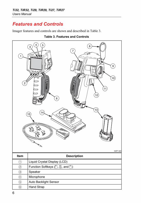
Features and Controls Imager features and controls are shown and described in Table 3.
Table 3. Features and Controls
POWER
Ti SBC3SMART BATTERY
CHARGER 3
1
34 5
7
2
6
1415
13
8
9
10
12
11
exj01.eps
Item Description
Liquid Crystal Display (LCD)
Function Softkeys (, , and )
Speaker
Microphone
Auto Backlight Sensor
Hand Strap
Thermal Imagers Using the Menu
7
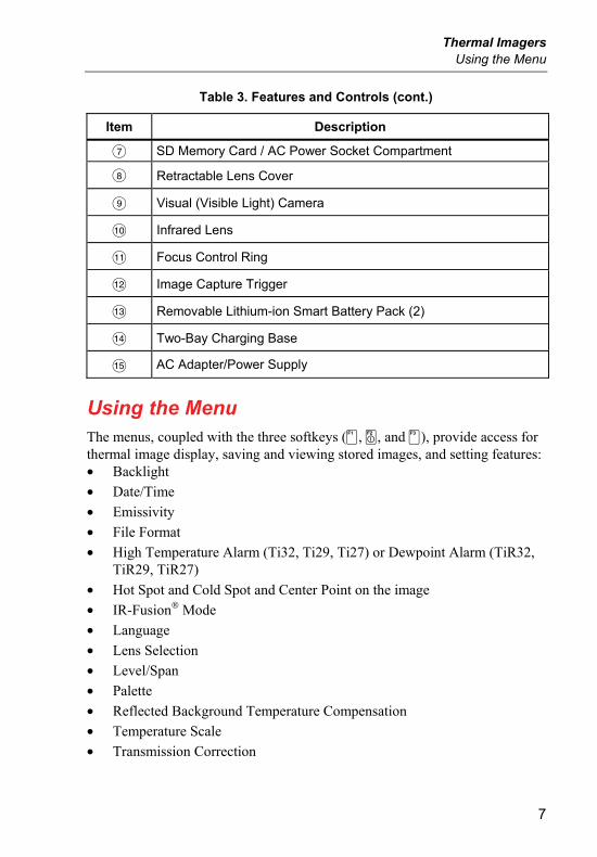
Table 3. Features and Controls (cont.)
Item Description
SD Memory Card / AC Power Socket Compartment
Retractable Lens Cover
Visual (Visible Light) Camera
Infrared Lens
Focus Control Ring
Image Capture Trigger
Removable Lithium-ion Smart Battery Pack (2)
Two-Bay Charging Base
AC Adapter/Power Supply
Using the Menu The menus, coupled with the three softkeys (, , and ), provide access for thermal image display, saving and viewing stored images, and setting features: • Backlight
• Date/Time
• Emissivity
• File Format
• High Temperature Alarm (Ti32, Ti29, Ti27) or Dewpoint Alarm (TiR32, TiR29, TiR27)
• Hot Spot and Cold Spot and Center Point on the image
• IR-Fusion® Mode
• Language
• Lens Selection
• Level/Span
• Palette
• Reflected Background Temperature Compensation
• Temperature Scale
• Transmission Correction
Ti32, TiR32, Ti29, TiR29, Ti27, TiR27 Users Manual
8
To bring up the menu, press . The text above each function softkey (, , and ) corresponds to that softkey throughout all menu screens.
Press to open and cycle through the menus.
The menu will automatically disappear several seconds after the last press of a softkey, and return the Imager to live view.
Menu Escape/Live View
To return to the live view immediately from most menu structures, quickly squeeze and release the trigger twice.
Basic User Preference Settings
Many Imager settings (level and span, transmission correction, alarms, emissivity, image browser, and background temperature) have an acceleration function that helps you rapidly change the selection. To accelerate through available options or numerical settings, press and hold or . Acceleration stops when you let go of the softkey.
Changing the Displayed Language
To change the display to present information in another language:
1. Press until the F3 softkey label reads Settings.
2. Press the softkey labeled Settings.
3. Within the Settings Menu, press , labeled Menu, until the F1 softkey reads Language.
4. Press the softkey labeled Language.
5. Press the softkey labeled Up or Down to move the cursor to the preferred language.
6. Press the softkey labeled Done to set the language.
7. Continue adjusting other items in the Settings Menu, or quickly squeeze and release the trigger twice in order to return to live view.
Thermal Imagers Using the Menu
9
Setting the Date
To set the date:
1. Press until the F3 softkey label reads Settings.
2. Press the softkey labeled Settings.
3. Within the Settings Menu, press , labeled Menu, until the F1 softkey reads Date.
4. Press the softkey labeled Date.
The date can be displayed in one of two formats: MM/DD/YY or DD/MM/YY.
5. Press the softkey labeled with the preferred date format.
6. Press the softkey labeled Up () or Down () to adjust the selected date element.
7. Press the softkey labeled Next to move to the next date element.
8. Press the softkey labeled Done when finished.
9. Continue adjusting other items in the Settings Menu, or quickly squeeze and release the trigger twice in order to return to live view.
Setting the Time
To set the time:
1. Press until the F3 softkey label reads Settings.
2. Press the softkey labeled Settings.
3. Within the Settings Menu, press , labeled Menu, until the F3 softkey reads Time.
4. Press the softkey labeled Time.
The Imager will display time in two different formats: 24 hour or 12 hour.
5. Press the softkey labeled with the preferred format.
6. Press the softkey labeled Up () or Down () to adjust the selected time element.
Ti32, TiR32, Ti29, TiR29, Ti27, TiR27 Users Manual
10
7. Press the softkey labeled Next to move to the next time element.
8. Press softkey labeled Done when finished.
9. Continue adjusting other items in the Settings Menu, or quickly squeeze and release the trigger twice in order to return to live view.
The 12 hour format has a selection for setting whether the time is AM or PM.
Changing the Temperature Units
The Imager will display temperature in Fahrenheit or Celsius. To change the temperature units:
1. Press until the F3 softkey label reads Settings.
2. Press the softkey labeled Settings.
3. Within the Settings Menu, press , labeled Menu, until the F3 softkey reads Units.
4. Press until Units is displayed over .
5. Press the softkey labeled Units.
6. Press for Celsius or for Fahrenheit.
7. Press the softkey labeled Done to set the units.
8. Continue adjusting other items in the Settings Menu, or quickly squeeze and release the trigger twice in order to return to live view.
Using the Centerbox Feature
The Centerbox feature allows the user to establish a temperature measurement zone (box), centered on the infrared image. This zone (box) expands and contracts to different levels within the infrared image. The zone allows the user to see an approximate maximum (MAX), average (AVG), and minimum (MIN) temperature measurement within the selected area.
Note
When the Centerbox feature is enabled, and the Spot Temp markers are also enabled, the Spot Temp markers will only work within the selected Centerbox area, instead of the full infrared field of view.
Thermal Imagers Using the Menu
11
To enable or disable the Centerbox feature:
1. Press F2 until Settings appears over F3.
2. Press softkey labeled Settings.
3. Press F2 until Centerbox appears over F3.
4. Press softkey labeled Enable to activate Centerbox feature.
5. Press softkey labeled Disable to deactivate Centerbox feature.
To set the size of the Centerbox when enabled:
1. Press to increase the size of the Centerbox.
2. Press to reduce the size of the Centerbox.
3. When satisfied with the size of the Centerbox, press Done to accept the setting.
4. Continue adjusting other items in the Settings menu, or quickly squeeze and release the trigger twice to return to the live view.
Setting File Format
Data stored on the Imager’s SD memory card can be saved in three different file formats: .bmp, .jpeg, and .is2. This setting is saved and remains valid when the Imager is turned off and back on. It can always be changed to another format prior to capturing images.
To change the file format:
1. Press until the F3 softkey label reads Settings.
2. Press the softkey labeled Settings.
3. Within the Settings Menu, press , labeled Menu, until the F1 softkey reads File Format.
4. Press until File Format appears over softkey F3.
5. Press the softkey labeled File Format.
6. Press the softkey labeled Up () or Down () to select either bitmap (.bmp) file format, jpeg (.jpeg/.jpg) format, or (.is2) file format according to your needs.
7. Press softkey labeled Done when finished.
Ti32, TiR32, Ti29, TiR29, Ti27, TiR27 Users Manual
12
8. Continue adjusting other items in the Settings Menu, or quickly squeeze and release the trigger twice in order to return to live view.
The bitmap and jpeg formats only save the image shown on the Imager’s display. The “.is2” format is a file format that saves all radiometric data, infrared image, IR-Fusion® mode information, palette information, full visual image, screen settings, and voice recording annotated to the stored image.
Bitmap (.bmp) or JPEG (.jpeg/.jpg) images can be transferred to a PC and used immediately in many types of software and electronic documents. Images in “.is2” format can be transferred to a PC for further analysis and report generation through Fluke SmartView® software or non-Fluke software that is available from specially approved software vendors. SmartView® converts the .is2 images as JPEG, BMP, GIF, TIFF, and PNG files. Visit the Fluke web site or contact Fluke to find out about currently available software options.
Setting the Backlight
The backlight can be set to Auto-sensing or Full-Bright. To set the backlight:
1. Press until the F3 softkey label reads Settings.
2. Press the softkey labeled Settings.
3. Within the Settings Menu, press , labeled Menu, until the F1 softkey reads Backlight.
4. Press the softkey labeled Backlight.
5. Press the softkey labeled Auto or Full-Bright.
6. Continue adjusting other items in the Settings Menu, or quickly squeeze and release the trigger twice in order to return to live view.
Note
To extend battery life, Auto-Sensing automatically adjusts backlight brightness based on ambient light levels.
Setting the Display Information Settings
The Imager allows you to choose from several different options for information display on the LCD. These include: Display All, Display Time/Date/Scale Only, Display Scale Only, and Display Image Only.
• Display All: date, time, scale bar, battery life indicator, emissivity setting, reflected background temperature setting, transmission setting, and optional lens (if selected).
Thermal Imagers How to Install and Use Optional Lenses (Telephoto and Wide-Angle)
13
• Display Date/Time/Scale: displays the date, time, scale bar, and battery life indicator.
• Display Scale: displays the scale bar and battery life indicator.
• Display Image Only: displays only the visible light or thermal image or combinations of both.
To change the display settings:
1. Press until the F3 softkey label reads Settings.
2. Press the softkey labeled Settings.
3. Within the Settings Menu, press , labeled Menu, until the F3 softkey reads Display.
4. Press the softkey labeled Display.
5. Press the softkey labeled Up () or Down () to select the information display option.
6. Press softkey labeled Done when finished.
7. Continue adjusting other items in the Settings Menu, or quickly squeeze and release the trigger twice in order to return to live view.
How to Install and Use Optional Lenses (Telephoto and Wide-Angle) The Imager is an extremely sensitive device that can detect temperature differences ≤50mK (0.05 °C). It allows minimum spans as low as 2 °C in many operating modes. Special palettes and palette modes are also offered in order to enhance and highlight very small thermal differences in a scene. In addition, optional telephoto and wide angle lenses are available to further enhance the anomaly detecting capability of the imagers.
Every effort is undertaken to produce a high quality, and radiometrically accurate infrared image under as many circumstances as possible. However, there are often extreme use situations under which the infrared energy being emitted from a target of interest is so small that the Imager reaches the limits of the physical (physics) properties, which govern its operation. Using the imager under these circumstances, can at times result in the appearance of light rings or a halo on the infrared image. This is completely normal.
Although it is possible to mitigate these artifacts by artificially adding electronic noise and additional processing to the infrared signal, Fluke has
Ti32, TiR32, Ti29, TiR29, Ti27, TiR27 Users Manual
14
chosen not to do so in order to preserve the extreme sensitivity of the instrument. If any of these artifacts do appear in your properly focused infrared image, please be assured that it is only because there is not enough of a thermal differential in the scene to indicate the presence of an anomaly or issue. In essence, the imager is so sensitive, that it is “seeing itself” optically, radiometrically, and electronically. Typically, increasing span, changing color palette, or introducing a thermal differential into the scene will eliminate the appearance of any artifacts, and will still allow the appropriate interpretation of the infrared image.
Optional telephoto and wide-angle lenses expand the flexibility and allow more applications for your infrared inspection work.
To install and use an optional lens on the Imager:
1. With your Imager OFF, insert the SD memory card with firmware codes for your optional lens into the SD memory card slot on the side of your Imager.
2. Turn on the Imager by pressing .
3. Follow directions displayed on the LCD to install the proper files onto the Imager’s internal memory.
4. After file installation, remove the SD memory card with the firmware files and reinsert the standard SD memory card used for storing images.
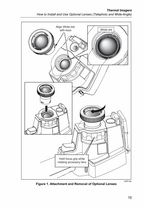
5. Attach the optional lens onto the Imager by aligning the dot on the lens with the dot on the Imager, see Figure 1.
6. Gently push optional lens into position and rotate clockwise until lens locks into proper position.
Note
It is important to select the proper lens option within your Imager’s Settings/Lens menu.
Thermal Imagers How to Install and Use Optional Lenses (Telephoto and Wide-Angle)
15
Align White dot with keys White dot
Hold focus grip whilerotating accessory lens
exj04.eps
Figure 1. Attachment and Removal of Optional Lenses

Ti32, TiR32, Ti29, TiR29, Ti27, TiR27 Users Manual
16
To select or change the lens in use on the Imager:
1. Press until the F3 softkey label reads Settings.
2. Press the softkey labeled Settings.
3. Within the Settings Menu, press , labeled Menu, until the F3 softkey reads Lens.
4. Press the softkey labeled Lens.
5. Press the softkey labeled Up () or Down () to select the lens.
6. Press the softkey labeled Done when finished.
7. Continue adjusting other items in the Settings Menu, or quickly squeeze and release the trigger twice to return to live view.
If you have the Display Information setting on your Imager set to Display All, a symbol appears with the wide-angle lens selection. A symbol appears on the lower part of the LCD with the telephoto lens selection. The default condition is the standard lens with no indicator symbol.
Note
IR-Fusion® is disabled when you set the Imager to the wide angle lens selection.
Caution Failure to select the proper lens on your Imager may result in inaccurate temperature measurement values.
When finished using the optional lens, remove it from the Imager:
1. Gently push in on the optional lens and rotate counter-clockwise until lens disengages from Imager.
2. Remove optional lens and replace properly with lens cap into its storage case.
3. Select the standard lens in the proper section of the menu system to return to normal operation with that lens.
Note
For the best protection and longest life, always remember to store an optional lens in its protective cases with the lens covers on.
Thermal Imagers Focusing and Capturing an Image
17
Focusing and Capturing an Image Point the Imager at the object or area of interest, focus by turning the focus control ring until the infrared image displayed on the LCD is as clear as possible, and then press and release the trigger. The Imager displays the captured image and a menu. The menu allows image storage, image setting adjustments, and recording of audio annotations for .is2 file format. To cancel image storage and return to live viewing, press and release the trigger.
Note
Minimum focus distance for infrared camera (with the standard lens) is 15 cm (approx. 6 inches). Minimum focus distance for visible (visual) light camera is 46 cm (approx. 18 inches).
Note
The Imager can save the image as a simple picture or as a radiometric image that allows further temperature analysis. To change the saved image format, see the “Setting File Format” section later in this manual.
Note
When IR-Fusion is enabled, adjusting the IR focus control will align the IR and visible light images on the LCD. When the IR image is properly focused, the images should be almost perfectly aligned. This functionality provides an easy method to get a good focus on the IR image. Because of image parallax and minimum focus specifications, the minimum distance for an aligned IR-Fusion image is approximately 46 cm (18 inches).
Pressing the softkey labeled Settings, within the Image Captured section, allows modification of image characteristics such as palette, picture-in-picture, and range in .is2 format files only. Refer to the appropriate setting section for operational details.
Saving Imager Data The Imager saves displayed data on an SD memory card placed into the camera. See the “Changing the SD Card” section for inserting and ejecting an SD memory card. The file format set on the Imager determines how the measured information is stored on the SD memory card. To store Imager data:
Ti32, TiR32, Ti29, TiR29, Ti27, TiR27 Users Manual
18
1. Point camera at the area of interest and pull the trigger to capture an image. This will freeze the image in the display and bring up the Image Capture menu.
2. Press the softkey labeled Store. If the SD memory card is in the Imager and there is enough room left on the card, the information is stored.
Caution Do not remove the SD memory card while storing an image. Image data may be lost.
Note
Before you store an image, make sure the write protect lock on the SD memory card is in the open position.
Adjusting the Thermal Image The Imager uses different colors or shades of gray to display the temperature gradient of the area within the Imager’s field of view. There are two adjustments for changing how the Imager displays the image: Palette and Range.
Selecting a Standard Palette
The palette menu provides different thermal viewing patterns. Grayscale, Blue-Red, High Contrast, Ironbow, Amber, and Hot Metal are available on both Imagers. To select a standard palette:
1. Press until Palette appears over .
2. Press the softkey labeled Palette to display the available palette options. (Standard or Ultra Contrast)
3. Press the softkey labeled Standard.
4. Press the softkey labeled Up or Down to move between the palette options.
5. Press the softkey labeled Done to set the Imager to the selected palette.
6. Wait for main menu to disappear or quickly squeeze and release the trigger twice in order to return to live view.
Thermal Imagers Adjusting the Thermal Image
19
Selecting an Ultra Contrast Palette
Ultra Contrast™ palettes are available for each standard palette listed above. To select an Ultra Contrast™ palette:
1. Press until Palette appears over .
2. Press the softkey labeled Palette to display the available palette options (Standard or Ultra Contrast).
3. Press the softkey labeled Ultra Contrast.
4. Press the softkey labeled Up or Down to move between the palette options.
5. Press the softkey labeled Done to set the Imager to the selected palette.
6. Wait for main menu to disappear or quickly squeeze and release the trigger twice in order to return to live view.
Setting the Range
Viewing temperature (level and span) is set either automatically or manually. To set the range, do the following:
1. Press until Range appears over .
2. Press the softkey labeled Range.
3. Press the softkey labeled Manual to set the Imager to manual ranging and press the softkey labeled Auto to select auto ranging.
When operating the Imager in Auto Range Mode, it will automatically determine a Level and Span based upon the infrared energy that it detects at any point in time. It re-calibrates automatically as the infrared energy in the Field of View changes. The temperature measurement scale updates accordingly, and “Auto” displays in the upper right-hand corner of the LCD.
When operating the Imager in Manual Range Mode, the Level and Span and the temperature measurement scale will have fixed settings unless the user chooses to manually adjust the Level and Span, or chooses to perform a Fast Auto Rescale (see following sections). The temperature measurement scale indicates “Manual” in the upper right hand corner of the LCD.
Ti32, TiR32, Ti29, TiR29, Ti27, TiR27 Users Manual
20
Fast Auto/Manual Range Toggle
When NOT in a menu mode, press for ½ second and release to toggle between Auto Range and Manual Range.
Fast Auto Rescale
When in Manual Range and NOT in a menu mode, press for ½ second and release to automatically rescale the level and span range for objects within the Imager’s thermal field of view.
Note
The Imager always powers up in the same Range mode, Auto or Manual, as when it powers down.
Setting the Level (Manual)
When in manual ranging, the level setting adjusts the mid-point thermal span within the total temperature range of the Imager. To set the level:
1. After entering the manual range mode (see “Setting the Range”), press the softkey labeled Go to Level. This will place the Imager into the Adjusting Level mode.
2. Press the softkey labeled Up to move the temperature span to higher temperatures or Down to move the span to lower temperatures.
3. To adjust the Span, press the softkey labeled Go to Span (see “Setting the Temperature Span”).
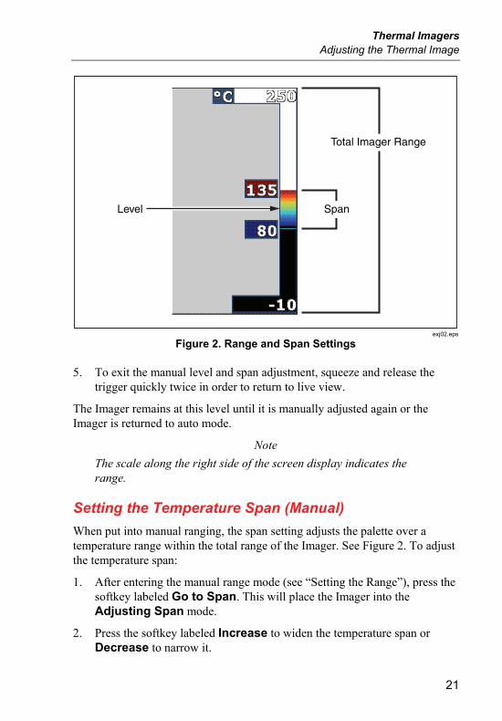
4. To capture an image, squeeze and release the trigger once. See Figure 2.
Thermal Imagers Adjusting the Thermal Image
21
Total Imager Range
SpanLevel
exj02.eps
Figure 2. Range and Span Settings
5. To exit the manual level and span adjustment, squeeze and release the trigger quickly twice in order to return to live view.
The Imager remains at this level until it is manually adjusted again or the Imager is returned to auto mode.
Note
The scale along the right side of the screen display indicates the range.
Setting the Temperature Span (Manual)
When put into manual ranging, the span setting adjusts the palette over a temperature range within the total range of the Imager. See Figure 2. To adjust the temperature span:
1. After entering the manual range mode (see “Setting the Range”), press the softkey labeled Go to Span. This will place the Imager into the Adjusting Span mode.
2. Press the softkey labeled Increase to widen the temperature span or Decrease to narrow it.
Ti32, TiR32, Ti29, TiR29, Ti27, TiR27 Users Manual
22
3. To adjust the Level, press the softkey labeled Go to Level (see “Setting the Level”).
4. To capture an image, squeeze and release the trigger once.
5. To exit the manual level and span adjustment, squeeze and release the trigger quickly twice in order to return to live view.
The Imager remains at this Span until it is manually adjusted again, or the Imager returns to auto mode.
Setting IR-Fusion and PIP IR-Fusion®, only from Fluke, allows the user to utilize various modes that combine a thermal image with a visual (visible light) image. The Imager is set to one of three different levels of blending. In addition to setting the visual to thermal blending, the IR-Fusion® menu is used to select between a full thermal image display and a Picture-In-Picture (PIP) display. To set the IR-Fusion® level and PIP display:
1. Press until IRFusion appears over .
2. Press the softkey labeled IRFusion to reveal the IR-Fusion® menu.
3. Press the softkey labeled Up or Down to move between the six IR-Fusion® settings. The top three settings select a PIP display. The bottom three settings have full screen IR with different levels of visible blending.
4. Press the softkey labeled Done when finished.
5. Wait for main menu to disappear or quickly squeeze and release the trigger twice in order to return to live view.
Reviewing and Deleting Stored Images To enter the Review mode and view stored images on the SD memory card:
1. Press until Review appears over .
2. Press the softkey labeled Review to bring up the thumbnail review of images stored in memory.
3. Press the softkey labeled Left and Right Arrows to navigate through the thumbnail images.
Thermal Imagers Adding Voice Annotation to Saved Data
23
4. When ready to review the details of a specific image, press the softkey labeled Select.
To delete a single Image from the SD memory card:
1. Perform the steps under viewing stored images to display the image.
2. Press the softkey labeled Select.
3. Press the softkey labeled Delete.
To delete all the images from the SD memory card:
1. Press the softkey labeled Select.
2. Press the softkey labeled Delete.
3. Press the softkey labeled All Images.
4. To exit Review mode, squeeze the trigger once to return to the live view.
Adding Voice Annotation to Saved Data Voice annotation can only be added to an image prior to storing it. After capturing an image, the Image Capture menu appears. To add a voice annotation to the image:
1. Press the softkey labeled Audio.
2. Press the softkey labeled Record to start the recording.
3. Speak into the Imager’s microphone opening. Up to 60 seconds of audio can be recorded for each image.
4. When done recording, press the softkey labeled Review to listen to what was recorded. When an audio recording has been created for an image, appears in the display while the image is displayed. To keep the audio annotation, proceed to the next step. Otherwise, press the softkey labeled Append or Replace to modify the recording before storing the image. Once stored, the audio annotation can only be reviewed and not modified.
5. Press the softkey labeled Back to return to the Audio menu.
6. Press the softkey labeled Store to store the measured data and audio annotation.
Ti32, TiR32, Ti29, TiR29, Ti27, TiR27 Users Manual
24
Listening to Voice Annotations To play the voice annotation already stored with an image on the SD memory card:
1. Perform the steps in the “Reviewing and Deleting Stored Images” section to select the image on the Imager’s display.
2. Press the softkey labeled Select.
3. Press the softkey labeled Audio.
4. Press the softkey labeled Review.
The saved voice annotation will be replayed through the Imager’s speaker.
Enabling/Disabling Spot Indicators To enable or disable the hot and cold spot indicators:
1. Press until Spot Temp appears over .
2. Press the softkey labeled Spot Temp.
3. Press the softkey labeled Off to turn the hot spot and cold spot indicators off or press the softkey labeled On to turn them on.
4. Press the softkey labeled Done to accept the setting.
5. Wait for the main menu to disappear or quickly squeeze and release the trigger twice in order to return to live view.
Making Accurate Temperature Measurements All objects on Earth radiate infrared energy. The amount of energy radiated is based on two primary factors: the surface temperature of the object and the emissivity of the object's surface. The Imager detects the infrared energy from an object and uses this information to estimate the temperature of the object. Most of the objects measured such as painted metal, wood, water, skin, and cloth are very efficient at radiating energy and it is easy to get very accurate measurements.
For surfaces that are efficient at radiating energy (high emissivity), the emissivity factor is estimated to be 95% (or 0.95). This estimate works for most purposes. This simplification does not work however, on shiny surfaces or unpainted metals. These materials are not efficient at radiating energy and are classified as having low emissivity. To accurately obtain a temperature
Thermal Imagers Setting Emissivity
25
measurement on materials with a low emissivity, an emissivity correction is often necessary. The easiest correction method is to set the Imager to the proper emissivity value so the Imager automatically calculates a corrected surface temperature. If the Imager uses a fixed emissivity value (meaning that it is set to one value and the user cannot adjust it), then the Imager’s measurement must be multiplied by a value found in a look up table to get a more accurate estimate of the actual temperature.
Regardless of an Imager’s ability to adjust for emissivity in calculating temperature measurements, surfaces with an emissivity of 0.60, or lower, are often difficult to obtain truly accurate temperature measurements without significant error. It is always best to change or improve the emissivity of a surface when possible if accurate temperature measurements are required.
The Imager has the ability to set emissivity by directly entering a value or using a table of built-in values. Much information is available on emissivity. Further study of this topic is recommended to get the most accurate temperature measurements using the Imager.
Note
All thermal imagers require appropriate warm-up time in order to obtain the most accurate temperature measurement and best image quality. This time can often vary by model and by environmental conditions. Although most imagers are fully warmed-up within 3-5 minutes, it is always a best practice to wait at least 10 minutes if the most accurate temperature measurement is critical to your application. Whenever changing or adding optional lenses, additional stabilization time may be required depending on the situation.
Setting Emissivity Setting your Imager with correct emissivity values is critical to making accurate temperature measurements. To set the emissivity value:
1. Press until Emissivity appears over .
2. Press the softkey labeled Emissivity.
At this point, emissivity can be set directly as a value or selected from a list of emissivity values for some common materials. To select from a list of common materials:
1. Press the softkey labeled Table.
Ti32, TiR32, Ti29, TiR29, Ti27, TiR27 Users Manual
26
2. Press the softkey labeled Up or Down to move between the materials in the list. The emissivity value for each material is shown on the screen as the selection moves between the different materials
3. Press the softkey labeled Done to select the highlighted material.
To set the emissivity value directly:
1. Press the softkey labeled ε.
2. Press the softkey labeled Up or Down to increment or decrement, respectively, the emissivity value displayed just above the softkey labels.
3. Press the softkey labeled Done to select the set value.
4. Wait for main menu to disappear or quickly squeeze and release the trigger twice in order to return to live view.
Note
If you have the Display Information setting on your Imager set to Display All, information on current emissivity settings can be see as “ε = xx”.
Setting Reflected Background Temperature (Reflected Temperature Compensation) Compensation for reflected background temperature on the Imager is set in the Background tab. Very hot or very cold objects may affect the temperature measurement accuracy of the target or object of interest, especially when surface emissivity is low. Adjustment of the reflected background temperature setting may improve temperature measurement accuracy.
1. Press until Background appears over .
2. Press softkey labeled Background.
3. Use the softkey labeled Up or Down to adjust the reflected background temperature.
4. Press Done when finished.
5. Wait for main menu to disappear or quickly squeeze and release the trigger twice in order to return to live view.
Thermal Imagers Setting Transmission Correction
27
Note
If you have the Display Information setting on your Imager set to Display All information on current reflected background temperature settings can be see as “BG = xx”.
Setting Transmission Correction When conducting infrared inspections through infrared-transparent windows (IR Windows / Sightglasses), not all of the infrared energy emitted from the objects of interest are efficiently transmitted through the optic material in the window. If the transmission rate of the window is known, you can adjust the transmission correction setting in the Imager or in SmartView® software. Adjustment of the transmission correction setting may improve temperature measurement accuracy.
1. Press until Transmission appears over .
2. Press softkey labeled Transmission.
3. Use the softkey labeled Up or Down to adjust for the transmission rate (%) of the material your Imager is looking through.
4. Press Done when finished.
5. Wait for main menu to disappear or quickly squeeze and release the trigger twice in order to return to live view.
Note
If you have the Display Information setting on your Imager set to “Display All”, information on current transmission correction settings can be see as “τ = xx”.
Setting Temperature Alarms The Imager has the ability to set a temperature alarm function. The Ti32, Ti29, and Ti27 have a high-temperature alarm that allows the Imager to display a full visible light image and only shows infrared information on objects or areas that are above the set alarm level. The TiR32, TiR29, and TiR27 have a dewpoint temperature alarm that allows the Imager to display a full visible light image and only show infrared information on objects or areas that are below the set dewpoint alarm level.
Ti32, TiR32, Ti29, TiR29, Ti27, TiR27 Users Manual
28
High Temperature Alarm (Ti32, Ti29, Ti27)
1. Press until Alarm appears over .
2. Press softkey labeled Alarm.
3. Press the softkey labeled Enable to enable the high-temperature alarm function. (Press the softkey labeled Disable to disable the high-temperature alarm function.)
4. When enabled, press the softkey labeled Up or Down to set the high-temperature alarm.
5. Press Done when finished.
6. Wait for main menu to disappear or quickly squeeze and release the trigger twice in order to return to live view.
Dewpoint Alarm (TiR32, TiR29, TiR27)
1. Press until Dewpoint appears over .
2. Press softkey labeled Dewpoint.
3. Press the softkey labeled Enable to enable the dewpoint alarm function.
4. Press the softkey labeled Disable to disable the high-temperature alarm function.
5. When enabled, press the softkey labeled Up or Down to set the dewpoint alarm.
6. Press Done when finished.
7. Wait for main menu to disappear or quickly squeeze and release the trigger twice in order to return to live view.
SmartView Software SmartView® software is supplied with Fluke Imagers. It contains functions to analyze images, organize data storage, and create professional reports. SmartView® allows audio annotations to be reviewed on a PC. SmartView® can be used to export IR and visible images as JPEG, BMP, GIF, TIFF, and PNG files.
Thermal Imagers Changing the SD Memory Card
29
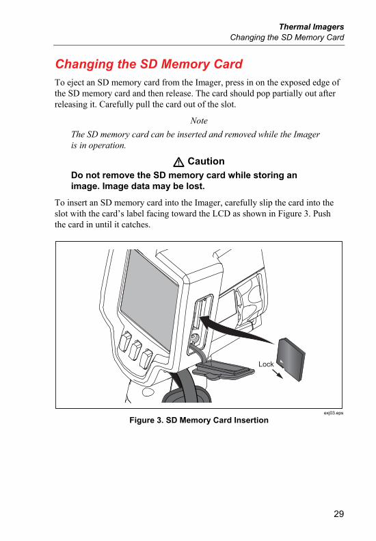
Changing the SD Memory Card To eject an SD memory card from the Imager, press in on the exposed edge of the SD memory card and then release. The card should pop partially out after releasing it. Carefully pull the card out of the slot.
Note
The SD memory card can be inserted and removed while the Imager is in operation.
Caution Do not remove the SD memory card while storing an image. Image data may be lost.
To insert an SD memory card into the Imager, carefully slip the card into the slot with the card’s label facing toward the LCD as shown in Figure 3. Push the card in until it catches.
Lock
exj03.eps
Figure 3. SD Memory Card Insertion
Ti32, TiR32, Ti29, TiR29, Ti27, TiR27 Users Manual
30
Maintenance The Imager supplies maintenance-free operation. However, some precautions should be followed to get the best and longest Imager performance.
Cleaning the Imager
Wipe the case with a damp cloth and a mild detergent. Do not use abrasives, isopropyl alcohol, or solvents to clean the case or lens/window.
Cleaning the Infrared Lens
If used and stored properly, the infrared lens on your Imager should require only occasional cleaning. When cleaning is necessary, observe these steps:
1. Using a hand-operated air bulb, gently blow off any dust or debris from the lens surface.
2. If the surface of the lens still requires additional cleaning after the first step, use a clean, fine-fiber or micro-fiber cloth, dampened with a mild, soapy water solution. Gently wipe surface of lens to remove remaining smudges, debris, or grime.
3. Dry with an absorbent, clean, fine-fiber or micro-fiber cloth.
Note
Minor smudges and grime should not significantly affect the performance of the Imager. However, large scratches or the removal of the protective coating on your infrared lens may affect both image quality and the temperature measurement accuracy.
Note
Use of alcohol, abrasives, solvents, or harsh detergents could damage not only the protective optical coating on the infrared lens, but also the sealing materials, rubber components, and adhesives in the lens assembly. Use of these items to clean the Imager or thermal lens will void the warranty.
Thermal Imagers Maintenance
31
Battery Care
To get the best performance from the Imager’s rechargeable Lithium-ion smart batteries, use the guidelines that follow.
Caution To avoid damage to the Imager, do not leave the camera exposed to a heat source or high-temperature environments, such as an unattended vehicle in the sun.
Do not store the Imager on the power supply/charger for more than 24 hours as reduced battery life may result.
Charge the Imager’s Lithium-ion smart batteries for a 2-hour minimum at least every six months to maximize battery life. Without use, the batteries will self-discharge in approximately six months. Batteries stored for long periods may require two to ten charging cycles before it reaches full capacity.
Always operate the Imager within the temperature range specified in the specifications labeled Temperature – Operating.
Caution Do not incinerate the Imager or battery. Go to Fluke’s website for recycling information.
Ti32, TiR32, Ti29, TiR29, Ti27, TiR27 Users Manual
32
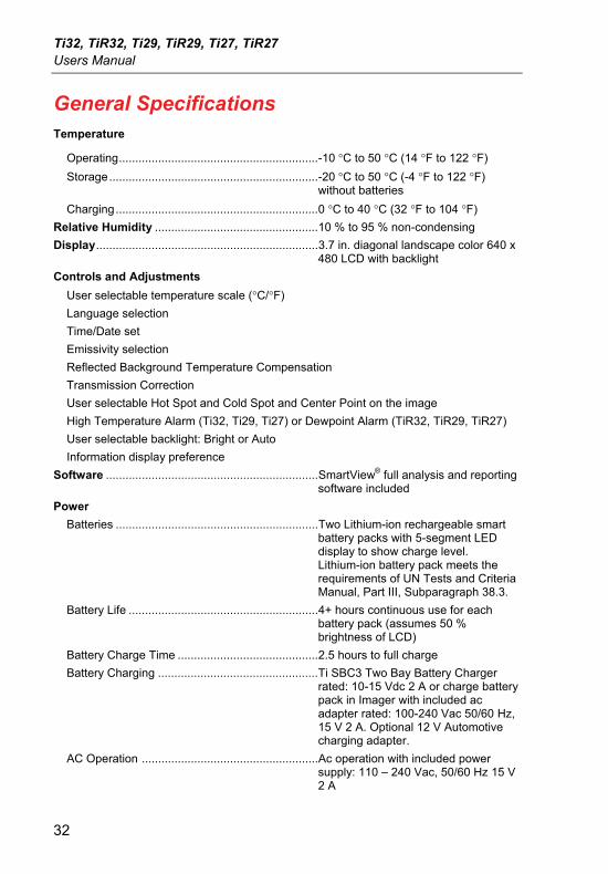
General Specifications Temperature
Operating.............................................................-10 °C to 50 °C (14 °F to 122 °F)
Storage................................................................-20 °C to 50 °C (-4 °F to 122 °F) without batteries
Charging..............................................................0 °C to 40 °C (32 °F to 104 °F)
Relative Humidity ..................................................10 % to 95 % non-condensing
Display....................................................................3.7 in. diagonal landscape color 640 x 480 LCD with backlight
Controls and Adjustments
User selectable temperature scale (°C/°F)
Language selection
Time/Date set
Emissivity selection
Reflected Background Temperature Compensation
Transmission Correction
User selectable Hot Spot and Cold Spot and Center Point on the image
High Temperature Alarm (Ti32, Ti29, Ti27) or Dewpoint Alarm (TiR32, TiR29, TiR27)
User selectable backlight: Bright or Auto
Information display preference
Software .................................................................SmartView® full analysis and reporting software included
Power
Batteries ..............................................................Two Lithium-ion rechargeable smart battery packs with 5-segment LED display to show charge level. Lithium-ion battery pack meets the requirements of UN Tests and Criteria Manual, Part III, Subparagraph 38.3.
Battery Life ..........................................................4+ hours continuous use for each battery pack (assumes 50 % brightness of LCD)
Battery Charge Time ...........................................2.5 hours to full charge
Battery Charging .................................................Ti SBC3 Two Bay Battery Charger rated: 10-15 Vdc 2 A or charge battery pack in Imager with included ac adapter rated: 100-240 Vac 50/60 Hz, 15 V 2 A. Optional 12 V Automotive charging adapter.
AC Operation ......................................................Ac operation with included power supply: 110 – 240 Vac, 50/60 Hz 15 V 2 A
Thermal Imagers Detailed Specifications
33
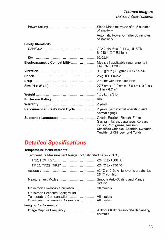
Power Saving...................................................... Sleep Mode activated after 5 minutes of inactivity
Automatic Power Off after 30 minutes of inactivity
Safety Standards
CAN/CSA............................................................ C22.2 No. 61010-1-04, UL STD 61010-1 (2nd Edition)
ISA ...................................................................... 82.02.01
Electromagnetic Compatibility ............................ Meets all applicable requirements in EN61326-1:2006
Vibration ................................................................ 0.03 g2/Hz (3.8 grms), IEC 68-2-6
Shock ..................................................................... 25 g, IEC 68-2-29
Drop ....................................................................... 2 meter with standard lens
Size (H x W x L) ..................................................... 27.7 cm x 12.2 cm x 17.0 cm (10.9 in x 4.8 in x 6.7 in)
Weight .................................................................... 1.05 kg (2.3 lb)
Enclosure Rating .................................................. IP54
Warranty ................................................................ 2 years
Recommended Calibration Cycle........................ 2 years (with normal operation and normal aging)
Supported Languages .......................................... Czech, English, Finnish, French, German, Italian, Japanese, Korean, Polish, Portuguese, Russian, Simplified Chinese, Spanish, Swedish, Traditional Chinese, and Turkish
Detailed Specifications Temperature Measurements
Temperature Measurement Range (not calibrated below -10 °C)
Ti32, Ti29, Ti27............................................... -20 °C to +600 °C
TiR32, TiR29, TiR27....................................... -20 °C to +150 °C
Accuracy ............................................................. ±2 °C or 2 %, whichever is greater (at 25 °C nominal)
Measurement Modes .......................................... Smooth Auto-Scaling and Manual Scaling
On-screen Emissivity Correction ........................ All models
On-screen Reflected Background Temperature Compensation............................... All models On-screen Transmission Correction .................. All models
Imaging Performance
Image Capture Frequency.................................. 9 Hz or 60 Hz refresh rate depending on model
Ti32, TiR32, Ti29, TiR29, Ti27, TiR27 Users Manual
34
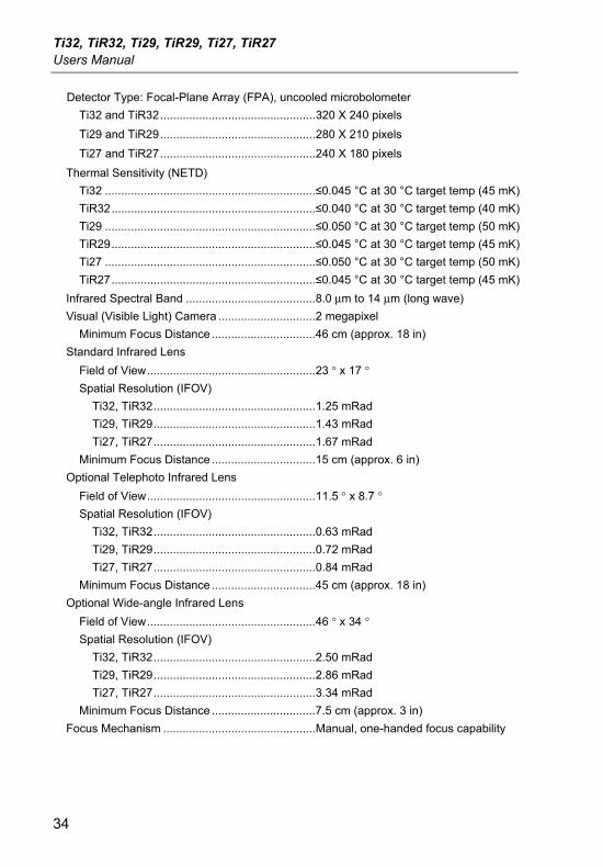
Detector Type: Focal-Plane Array (FPA), uncooled microbolometer
Ti32 and TiR32................................................320 X 240 pixels
Ti29 and TiR29................................................280 X 210 pixels
Ti27 and TiR27................................................240 X 180 pixels
Thermal Sensitivity (NETD)
Ti32 .................................................................≤0.045 °C at 30 °C target temp (45 mK)
TiR32...............................................................≤0.040 °C at 30 °C target temp (40 mK)
Ti29 .................................................................≤0.050 °C at 30 °C target temp (50 mK)
TiR29...............................................................≤0.045 °C at 30 °C target temp (45 mK)
Ti27 .................................................................≤0.050 °C at 30 °C target temp (50 mK)
TiR27...............................................................≤0.045 °C at 30 °C target temp (45 mK)
Infrared Spectral Band ........................................8.0 μm to 14 μm (long wave)
Visual (Visible Light) Camera ..............................2 megapixel
Minimum Focus Distance ................................46 cm (approx. 18 in)
Standard Infrared Lens
Field of View....................................................23 ° x 17 ° Spatial Resolution (IFOV)
Ti32, TiR32..................................................1.25 mRad
Ti29, TiR29..................................................1.43 mRad
Ti27, TiR27..................................................1.67 mRad
Minimum Focus Distance ................................15 cm (approx. 6 in)
Optional Telephoto Infrared Lens
Field of View....................................................11.5 ° x 8.7 ° Spatial Resolution (IFOV)
Ti32, TiR32..................................................0.63 mRad
Ti29, TiR29..................................................0.72 mRad
Ti27, TiR27..................................................0.84 mRad
Minimum Focus Distance ................................45 cm (approx. 18 in)
Optional Wide-angle Infrared Lens
Field of View....................................................46 ° x 34 ° Spatial Resolution (IFOV)
Ti32, TiR32..................................................2.50 mRad
Ti29, TiR29..................................................2.86 mRad
Ti27, TiR27..................................................3.34 mRad
Minimum Focus Distance ................................7.5 cm (approx. 3 in)
Focus Mechanism ...............................................Manual, one-handed focus capability
Thermal Imagers Detailed Specifications
35
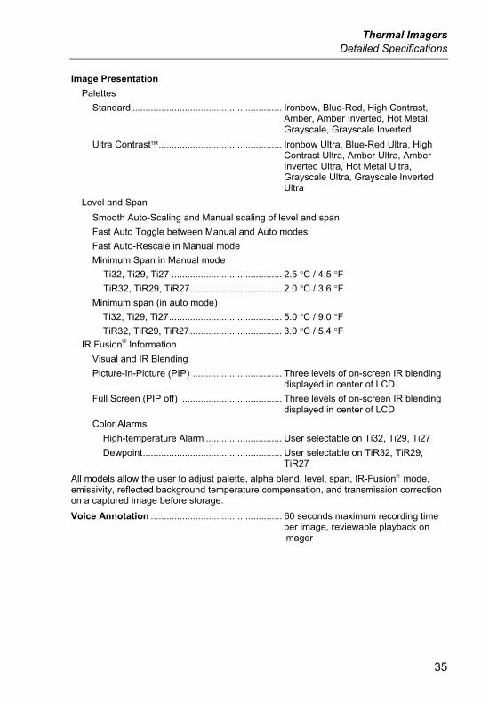
Image Presentation
Palettes
Standard ......................................................... Ironbow, Blue-Red, High Contrast, Amber, Amber Inverted, Hot Metal, Grayscale, Grayscale Inverted
Ultra Contrast............................................... Ironbow Ultra, Blue-Red Ultra, High Contrast Ultra, Amber Ultra, Amber Inverted Ultra, Hot Metal Ultra, Grayscale Ultra, Grayscale Inverted Ultra
Level and Span
Smooth Auto-Scaling and Manual scaling of level and span
Fast Auto Toggle between Manual and Auto modes
Fast Auto-Rescale in Manual mode
Minimum Span in Manual mode
Ti32, Ti29, Ti27 .......................................... 2.5 °C / 4.5 °F
TiR32, TiR29, TiR27................................... 2.0 °C / 3.6 °F
Minimum span (in auto mode)
Ti32, Ti29, Ti27........................................... 5.0 °C / 9.0 °F
TiR32, TiR29, TiR27................................... 3.0 °C / 5.4 °F
IR Fusion® Information
Visual and IR Blending
Picture-In-Picture (PIP) .................................. Three levels of on-screen IR blending displayed in center of LCD
Full Screen (PIP off) ...................................... Three levels of on-screen IR blending displayed in center of LCD
Color Alarms
High-temperature Alarm ............................. User selectable on Ti32, Ti29, Ti27
Dewpoint..................................................... User selectable on TiR32, TiR29, TiR27
All models allow the user to adjust palette, alpha blend, level, span, IR-Fusion mode, emissivity, reflected background temperature compensation, and transmission correction on a captured image before storage.
Voice Annotation .................................................. 60 seconds maximum recording time per image, reviewable playback on imager
Ti32, TiR32, Ti29, TiR29, Ti27, TiR27 Users Manual
36
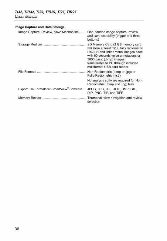
Image Capture and Data Storage
Image Capture, Review, Save Mechanism .........One-handed image capture, review, and save capability (trigger and three buttons)
Storage Medium ..................................................SD Memory Card (2 GB memory card will store at least 1200 fully radiometric (.is2) IR and linked visual images each with 60 seconds voice annotations or 3000 basic (.bmp) images, transferable to PC through included multiformat USB card reader
File Formats ........................................................Non-Radiometric (.bmp or .jpg) or Fully-Radiometric (.is2)
No analysis software required for Non-Radiometric (.bmp and .jpg) files
Export File Formats w/ SmartView® Software .....JPEG, JPG, JPE, JFIF, BMP, GIF, DIP, PNG, TIF, and TIFF
Memory Review...................................................Thumbnail view navigation and review selection