thz-b - フォトテクニカ株式会社 · sensor pyroelectric pyroelectric pyroelectric absorber...
TRANSCRIPT
THZ-B
BEAM
DIA
GNOS
TICS
SPEC
IAL
PROD
UCTS
OEM
DET
ECTO
RSPH
OTO
DETE
CTOR
SHI
GH P
OWER
SOL
UTIO
NS
POW
ER D
ETEC
TORS
ENER
GY D
ETEC
TORS
MON
ITOR
S T
HZ D
ETEC
TORS
T H Z D E T E C T O R S
SDC-500 DigitalOptical Chopper
Winston Cone Pelican Carrying CaseT-Rad-AnalogAnalog Power Supply
Stand with Delrin Post(Model Number: 200428)
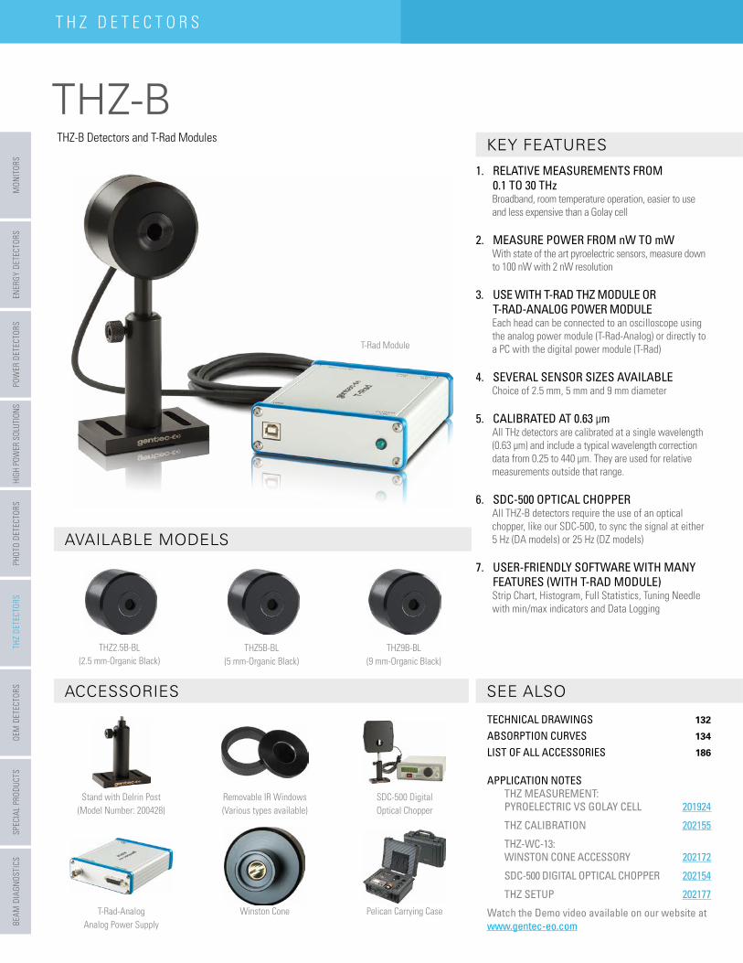
1. RELATIVE MEASUREMENTS FROM 0.1 TO 30 THzBroadband, room temperature operation, easier to use and less expensive than a Golay cell
2. MEASURE POWER FROM nW TO mWWith state of the art pyroelectric sensors, measure down to 100 nW with 2 nW resolution
3. USE WITH T-RAD THZ MODULE OR T-RAD-ANALOG POWER MODULEEach head can be connected to an oscilloscope using the analog power module (T-Rad-Analog) or directly to a PC with the digital power module (T-Rad)
4. SEVERAL SENSOR SIZES AVAILABLEChoice of 2.5 mm, 5 mm and 9 mm diameter
5. CALIBRATED AT 0.63 µmAll THz detectors are calibrated at a single wavelength (0.63 µm) and include a typical wavelength correction data from 0.25 to 440 µm. They are used for relative measurements outside that range.
6. SDC-500 OPTICAL CHOPPERAll THZ-B detectors require the use of an optical chopper, like our SDC-500, to sync the signal at either 5 Hz (DA models) or 25 Hz (DZ models)
7. USER-FRIENDLY SOFTWARE WITH MANY FEATURES (WITH T-RAD MODULE)Strip Chart, Histogram, Full Statistics, Tuning Needle with min/max indicators and Data Logging
THZ-B Detectors and T-Rad Modules
THZ2.5B-BL(2.5 mm-Organic Black)
THZ5B-BL(5 mm-Organic Black)
THZ9B-BL(9 mm-Organic Black)
T-Rad Module
AVAILABLE MODELS
ACCESSORIES SEE ALSO
KEY FEATURES
Removable IR Windows(Various types available)
TECHNICAL DRAWINGS 132
ABSORPTION CURVES 134
LIST OF ALL ACCESSORIES 186
APPLICATION NOTESTHZ MEASUREMENT: PYROELECTRIC VS GOLAY CELL 201924
THZ CALIBRATION 202155
THZ-WC-13: WINSTON CONE ACCESSORY 202172
SDC-500 DIGITAL OPTICAL CHOPPER 202154
THZ SETUP 202177
Watch the Demo video available on our website at www.gentec-eo.com
THZ-B
Catalogue 2016_V1.0 .com
BEAM DIAGNOSTICS
SPECIAL PRODUCTSOEM
DETECTORSPHOTO DETECTORS
HIGH POWER SOLUTIONS
POWER DETECTORS
ENERGY DETECTORSM
ONITORS THZ DETECTORS
T H Z D E T E C T O R S
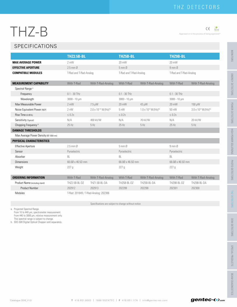
THZ2.5B-BL THZ5B-BL THZ9B-BLMAX AVERAGE POWER 2 mW 20 mW 20 mW
EFFECTIVE APERTURE 2.5 mm Ø 5 mm Ø 9 mm Ø
COMPATIBLE MODULES T-Rad and T-Rad-Analog T-Rad and T-Rad-Analog T-Rad and T-Rad-Analog
MEASUREMENT CAPABILITY With T-Rad With T-Rad-Analog With T-Rad With T-Rad-Analog With T-Rad With T-Rad-Analog
Spectral Range a
Frequency 0.1 - 30 THz 0.1 - 30 THz 0.1 - 30 THz
Wavelength 3000 - 10 µm 3000 - 10 µm 3000 - 10 µm
Max Measurable Power 2 mW 7.5 µW 20 mW 43 µW 20 mW 150 µW
Noise Equivalent Power (NEP) 2 nW 2.0 x 10⁻¹⁰ W/(Hz)½ 5 nW 1.0 x 10⁻⁹ W/(Hz)½ 50 nW 3.0 x 10⁻⁹ W/(Hz)½
Rise Time (0-95%) ≤ 0.2s ≤ 0.2s ≤ 0.2s
Sensitivity (Typical) N/A 400 kV/W N/A 70 kV/W N/A 20 kV/W
Chopping Frequency b 25 Hz 5 Hz 25 Hz 5 Hz 25 Hz 5 Hz
DAMAGE THRESHOLDSMax Average Power Density (@ 1064 nm)
PHYSICAL CHARACTERISTICS
Effective Aperture 2.5 mm Ø 5 mm Ø 9 mm Ø
Sensor Pyroelectric Pyroelectric Pyroelectric
Absorber BL BL BL
Dimensions 66.0Ø x 46.5D mm 66.0Ø x 46.5D mm 66.0Ø x 46.5D mm
Weight 227 g 227 g 227 g
ORDERING INFORMATION With T-Rad With T-Rad-Analog With T-Rad With T-Rad-Analog With T-Rad With T-Rad-Analog
Product Name (including stand) THZ2.5B-BL-DZ THZ1.5B-BL-DA THZ5B-BL-DZ THZ5B-BL-DA THZ9B-BL-DZ THZ9B-BL-DA
Product Number 202912 202913 202299 202298 202301 202300
Modules T-Rad: 201849 / T-Rad-Analog: 202306
Specifi cations are subject to change without notice
a. Projected Spectral Range.From 10 to 440 µm, spectrometer measurement.From 440 to 3000 µm, relative measurement only.This spectral range is subject to change.
b. SDC-500 Digital Optical Chopper sold separately.
SPECIFICATIONS
T 418.651.8003 | 1888 5GENTEC | F 418.651.1174 | [email protected]
THZ-B
BEAM
DIA
GNOS
TICS
SPEC
IAL
PROD
UCTS
OEM
DET
ECTO
RSPH
OTO
DETE
CTOR
SHI
GH P
OWER
SOL
UTIO
NS
POW
ER D
ETEC
TORS
ENER
GY D
ETEC
TORS
MON
ITOR
S T
HZ D
ETEC
TORS
T H Z D E T E C T O R S
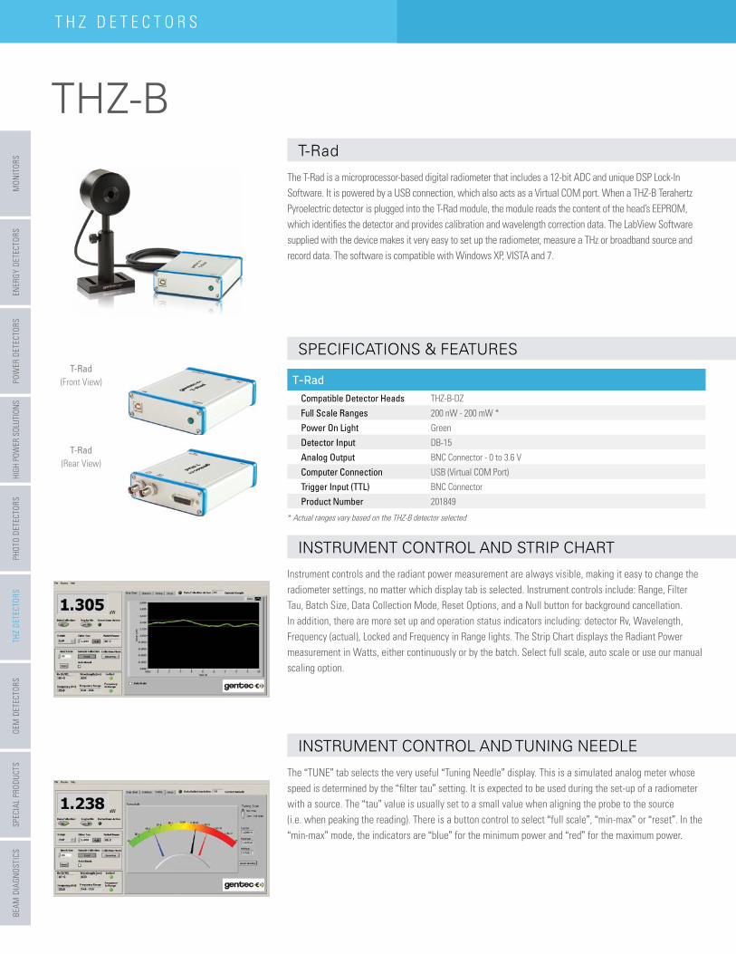
The T-Rad is a microprocessor-based digital radiometer that includes a 12-bit ADC and unique DSP Lock-In Software. It is powered by a USB connection, which also acts as a Virtual COM port. When a THZ-B Terahertz Pyroelectric detector is plugged into the T-Rad module, the module reads the content of the head’s EEPROM, which identifi es the detector and provides calibration and wavelength correction data. The LabView Software supplied with the device makes it very easy to set up the radiometer, measure a THz or broadband source and record data. The software is compatible with Windows XP, VISTA and 7.
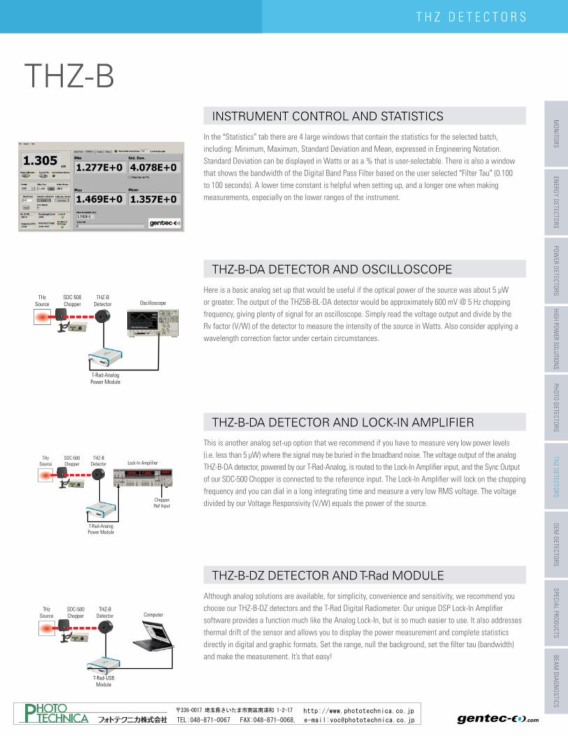
In the “Statistics” tab there are 4 large windows that contain the statistics for the selected batch, including: Minimum, Maximum, Standard Deviation and Mean, expressed in Engineering Notation. Standard Deviation can be displayed in Watts or as a % that is user-selectable. There is also a window that shows the bandwidth of the Digital Band Pass Filter based on the user selected “Filter Tau” (0.100 to 100 seconds). A lower time constant is helpful when setting up, and a longer one when making measurements, especially on the lower ranges of the instrument.
Here is a basic analog set up that would be useful if the optical power of the source was about 5 µW or greater. The output of the THZ5B-BL-DA detector would be approximately 600 mV @ 5 Hz chopping frequency, giving plenty of signal for an oscilloscope. Simply read the voltage output and divide by the Rv factor (V/W) of the detector to measure the intensity of the source in Watts. Also consider applying a wavelength correction factor under certain circumstances.
Instrument controls and the radiant power measurement are always visible, making it easy to change the radiometer settings, no matter which display tab is selected. Instrument controls include: Range, Filter Tau, Batch Size, Data Collection Mode, Reset Options, and a Null button for background cancellation. In addition, there are more set up and operation status indicators including: detector Rv, Wavelength, Frequency (actual), Locked and Frequency in Range lights. The Strip Chart displays the Radiant Power measurement in Watts, either continuously or by the batch. Select full scale, auto scale or use our manual scaling option.
This is another analog set-up option that we recommend if you have to measure very low power levels (i.e. less than 5 µW) where the signal may be buried in the broadband noise. The voltage output of the analog THZ-B-DA detector, powered by our T-Rad-Analog, is routed to the Lock-In Amplifi er input, and the Sync Output of our SDC-500 Chopper is connected to the reference input. The Lock-In Amplifi er will lock on the chopping frequency and you can dial in a long integrating time and measure a very low RMS voltage. The voltage divided by our Voltage Responsivity (V/W) equals the power of the source.
The “TUNE” tab selects the very useful “Tuning Needle” display. This is a simulated analog meter whose speed is determined by the “fi lter tau” setting. It is expected to be used during the set-up of a radiometer with a source. The “tau” value is usually set to a small value when aligning the probe to the source (i.e. when peaking the reading). There is a button control to select “full scale”, “min-max” or “reset”. In the “min-max” mode, the indicators are “blue” for the minimum power and “red” for the maximum power.
Although analog solutions are available, for simplicity, convenience and sensitivity, we recommend you choose our THZ-B-DZ detectors and the T-Rad Digital Radiometer. Our unique DSP Lock-In Amplifi er software provides a function much like the Analog Lock-In, but is so much easier to use. It also addresses thermal drift of the sensor and allows you to display the power measurement and complete statistics directly in digital and graphic formats. Set the range, null the background, set the fi lter tau (bandwidth) and make the measurement. It’s that easy!
T-Rad INSTRUMENT CONTROL AND STATISTICS
THZ-B-DA DETECTOR AND OSCILLOSCOPE
INSTRUMENT CONTROL AND STRIP CHART THZ-B-DA DETECTOR AND LOCK-IN AMPLIFIER
INSTRUMENT CONTROL AND TUNING NEEDLE THZ-B-DZ DETECTOR AND T-Rad MODULE
T-RadCompatible Detector Heads THZ-B-DZFull Scale Ranges 200 nW - 200 mW *Power On Light GreenDetector Input DB-15Analog Output BNC Connector - 0 to 3.6 VComputer Connection USB (Virtual COM Port)Trigger Input (TTL) BNC ConnectorProduct Number 201849
* Actual ranges vary based on the THZ-B detector selected
T-Rad(Front View)
T-Rad(Rear View)
THzSource
THZ-BDetector Lock-In Amplifier
ChopperRef Input
SDC-500Chopper
T-Rad-AnalogPower Module
Computer
T-Rad-USBModule
THzSource
THZ-BDetector
SDC-500Chopper
THzSource Oscilloscope
T-Rad-AnalogPower Module
THZ-BDetector
SDC-500Chopper
SPECIFICATIONS & FEATURES
THZ-B
Catalogue 2016_V1.0 .com
BEAM DIAGNOSTICS
SPECIAL PRODUCTSOEM
DETECTORSPHOTO DETECTORS
HIGH POWER SOLUTIONS
POWER DETECTORS
ENERGY DETECTORSM
ONITORS THZ DETECTORS
T H Z D E T E C T O R S
The T-Rad is a microprocessor-based digital radiometer that includes a 12-bit ADC and unique DSP Lock-In Software. It is powered by a USB connection, which also acts as a Virtual COM port. When a THZ-B Terahertz Pyroelectric detector is plugged into the T-Rad module, the module reads the content of the head’s EEPROM, which identifi es the detector and provides calibration and wavelength correction data. The LabView Software supplied with the device makes it very easy to set up the radiometer, measure a THz or broadband source and record data. The software is compatible with Windows XP, VISTA and 7.
In the “Statistics” tab there are 4 large windows that contain the statistics for the selected batch, including: Minimum, Maximum, Standard Deviation and Mean, expressed in Engineering Notation. Standard Deviation can be displayed in Watts or as a % that is user-selectable. There is also a window that shows the bandwidth of the Digital Band Pass Filter based on the user selected “Filter Tau” (0.100 to 100 seconds). A lower time constant is helpful when setting up, and a longer one when making measurements, especially on the lower ranges of the instrument.
Here is a basic analog set up that would be useful if the optical power of the source was about 5 µW or greater. The output of the THZ5B-BL-DA detector would be approximately 600 mV @ 5 Hz chopping frequency, giving plenty of signal for an oscilloscope. Simply read the voltage output and divide by the Rv factor (V/W) of the detector to measure the intensity of the source in Watts. Also consider applying a wavelength correction factor under certain circumstances.
Instrument controls and the radiant power measurement are always visible, making it easy to change the radiometer settings, no matter which display tab is selected. Instrument controls include: Range, Filter Tau, Batch Size, Data Collection Mode, Reset Options, and a Null button for background cancellation. In addition, there are more set up and operation status indicators including: detector Rv, Wavelength, Frequency (actual), Locked and Frequency in Range lights. The Strip Chart displays the Radiant Power measurement in Watts, either continuously or by the batch. Select full scale, auto scale or use our manual scaling option.
This is another analog set-up option that we recommend if you have to measure very low power levels (i.e. less than 5 µW) where the signal may be buried in the broadband noise. The voltage output of the analog THZ-B-DA detector, powered by our T-Rad-Analog, is routed to the Lock-In Amplifi er input, and the Sync Output of our SDC-500 Chopper is connected to the reference input. The Lock-In Amplifi er will lock on the chopping frequency and you can dial in a long integrating time and measure a very low RMS voltage. The voltage divided by our Voltage Responsivity (V/W) equals the power of the source.
The “TUNE” tab selects the very useful “Tuning Needle” display. This is a simulated analog meter whose speed is determined by the “fi lter tau” setting. It is expected to be used during the set-up of a radiometer with a source. The “tau” value is usually set to a small value when aligning the probe to the source (i.e. when peaking the reading). There is a button control to select “full scale”, “min-max” or “reset”. In the “min-max” mode, the indicators are “blue” for the minimum power and “red” for the maximum power.
Although analog solutions are available, for simplicity, convenience and sensitivity, we recommend you choose our THZ-B-DZ detectors and the T-Rad Digital Radiometer. Our unique DSP Lock-In Amplifi er software provides a function much like the Analog Lock-In, but is so much easier to use. It also addresses thermal drift of the sensor and allows you to display the power measurement and complete statistics directly in digital and graphic formats. Set the range, null the background, set the fi lter tau (bandwidth) and make the measurement. It’s that easy!
T-Rad INSTRUMENT CONTROL AND STATISTICS
THZ-B-DA DETECTOR AND OSCILLOSCOPE
INSTRUMENT CONTROL AND STRIP CHART THZ-B-DA DETECTOR AND LOCK-IN AMPLIFIER
INSTRUMENT CONTROL AND TUNING NEEDLE THZ-B-DZ DETECTOR AND T-Rad MODULE
T-RadCompatible Detector Heads THZ-B-DZFull Scale Ranges 200 nW - 200 mW *Power On Light GreenDetector Input DB-15Analog Output BNC Connector - 0 to 3.6 VComputer Connection USB (Virtual COM Port)Trigger Input (TTL) BNC ConnectorProduct Number 201849
* Actual ranges vary based on the THZ-B detector selected
T-Rad(Front View)
T-Rad(Rear View)
THzSource
THZ-BDetector Lock-In Amplifier
ChopperRef Input
SDC-500Chopper
T-Rad-AnalogPower Module
Computer
T-Rad-USBModule
THzSource
THZ-BDetector
SDC-500Chopper
THzSource Oscilloscope
T-Rad-AnalogPower Module
THZ-BDetector
SDC-500Chopper
SPECIFICATIONS & FEATURES
TEL:048-871-0067 FAX:048-871-0068, e-mail:[email protected]
http://www.phototechnica.co.jp〒336-0017 埼玉県さいたま市南区南浦和 1-2-17