thrust measurement system - isro
TRANSCRIPT

Page 1 of 21
Annexure-1
THRUST MEASUREMENT SYSTEM
A new test facility is being established at ISRO Propulsion Complex, Mahendragiri,
Tirunelveli, Tamil Nadu for static testing of high thrust rocket engines. To physically measure
the thrust developed by rocket engine during static testing, a Thrust Measurement System
(TMS) is planned in the facility. This tender is meant for Supply and Site installation of Thrust
Measurement System as per technical specification and conditions detailed hereunder.
1. Scope of Work
The scope of Bidder in brief includes:
1.1. Procurement of raw material and bought out items.
1.2. Precision fabrication of parts as per tolerances, machining & stress relieving requirements
given in drawings.
1.3. Trial assembly of TMS structure and qualification load testing at Manufacturer’s shop.
1.4. Painting, Packing, Transportation of TMS parts to site and safe unloading of items at site.
1.5. Site installation of TMS.
1.6. Final acceptance load testing at site.
1.7. Stage wise inspection of TMS parts from raw material procurement to final load testing at site
along with reputed Third Party Inspection agency (to be engaged by Bidder).
2. System Description
Thrust Measurement System is an assembly of structural elements and load cells specifically
designed to transfer thrust load from rocket engine to the ground structure called Engine Bay
Loading Frame and thereby accurately measure the thrust load generated by Engine.
Loading Frame is the main load carrying steel structure realized by Department at site. It is a
16m tall steel structure with four inclined columns supporting top deck structure of size
10mx10m with circular opening of Ø3.5m in the center. Loading Frame Structure weighs about
350 ton made up of BIS 2062 E250 Grade B Plates. It is supported by a massive concrete
foundation which houses the open J type flame deflector pit of depth 30 m from ground level.
Three tensile type load cells each of capacity 100 ton is used in TMS for measuring the engine
thrust. These load cells will be given as Free Issue Material by Department at site at the time of
site installation.

Page 2 of 21
Bidder shall have a complete understanding of items indented, its functional & manufacturing
requirements specified in drawings for ensuring satisfactory realization and installation of TMS
at site. The major subsystems in Thrust Measurement System are as follows:
Sl.
No.
Subsystem/
Component
Description
1. Fixed Frame
and interface
plate
Fixed Frame interfaces between Loading Frame and Thrust Frame. The top ring
of the Fixed Frame is connected through bolts with the Loading Frame. The
bottom ring of Fixed Frame is connected to the Thrust Frame through
Measurement Link Assembly. This structure transfers the total thrust load to
Loading Frame.
An Interface Plate is provided between the Loading Frame and top ring of Fixed
Frame. It is provided with tapped holes to attach Fixed Frame. Interface plate
has to be welded with the Loading Frame at site.
2. Thrust Frame Thrust Frame interfaces between Spacer Frame and Fixed Frame. The top ring
of Thrust Frame is interfaced to the bottom ring of Fixed Frame through
Measurement Link Assembly. The bottom ring of Thrust Frame is connected to
Spacer Frame. This is a floating member that transfers load generated by Engine
to the Fixed Frame through Measurement Link Assembly which measures the
thrust force developed by Engine.
3. Spacer Frame Spacer Frame interfaces Engine with Thrust Frame. It is attached to the bottom
ring of Thrust Frame by bolting arrangement.
4. Measurement
Links
Measurement Link interfaces between the Fixed Frame and Thrust Frame. It
connects the top ring of Thrust Frame with bottom ring of Fixed Frame. It
consists of Load Cells and adaptors. It measures the thrust load developed by
Engine.
5. Calibration
Frame and
interface plate
Calibration Frame interfaces between the Loading Frame and 1000T Hydraulic
Jack. The top ring of Calibration Frame is connected to Hydraulic Jack while its
bottom ring is connected to Engine Loading Frame. The purpose of this frame is
to transfer the load generated by hydraulic jack to Engine Loading Frame
during insitu calibration of TMS.
An Interface Plate is provided between the Engine Bay Loading Frame and
Calibration Frame. It is provided with tapped holes to attach Calibration Frame.
Interface plate has to be welded with the Engine Bay Loading Frame at site.

Page 3 of 21
6. Calibration
Link
Calibration Link interfaces between 1000T Hydraulic Jack and Calibration
Plate. It consists of Load Cells and adaptors. It measures the load generated by
the Hydraulic Jack during in-situ Calibration and transfers this load to the
Calibration Plate
7. Calibration
Plate
Calibration Plate interfaces between Calibration Link and Spacer Frame. It
transfers the load from Calibration Link to Spacer Frame during in-situ
calibration of TMS.
8. Preload Frame Preload setup is used during testing process. The preload frame is attached to
the Engine Bay Loading Frame and it supports dead weight with a Pulley Block
assembly. It is meant for keeping load cells always in tension. The Preload
frame is bolted to the Calibration Interface Plate.
9. Pulley block The pulley Block assembly is used to suspend the preload weight and transfer
the load of dead weight suspended to Load Cells.
10. Preload plates The preload Plates of mass 16 tonnes are used to ensure that Load Cells are
always in tension mode for better accuracy in measurement.
11. Side load links The side Load Links are used to ensure that forces and moments in lateral
directions are transferred from Thrust Frame to Fixed Frame. These are
interfaced with Fixed Frame through Bearings and Side Frames.
12. Side Frame Side Frames interface between Side Load Links and the Fixed Frames.
13. Load Test
Fixture
This fixture will be used to carry out load test of the TMS at shop in assembled
condition using the 1000T Hydraulic Jack. During load test, top ring of the
frame interfaces with Calibration Frame while the bottom ring will interface
with Fixed Frame.
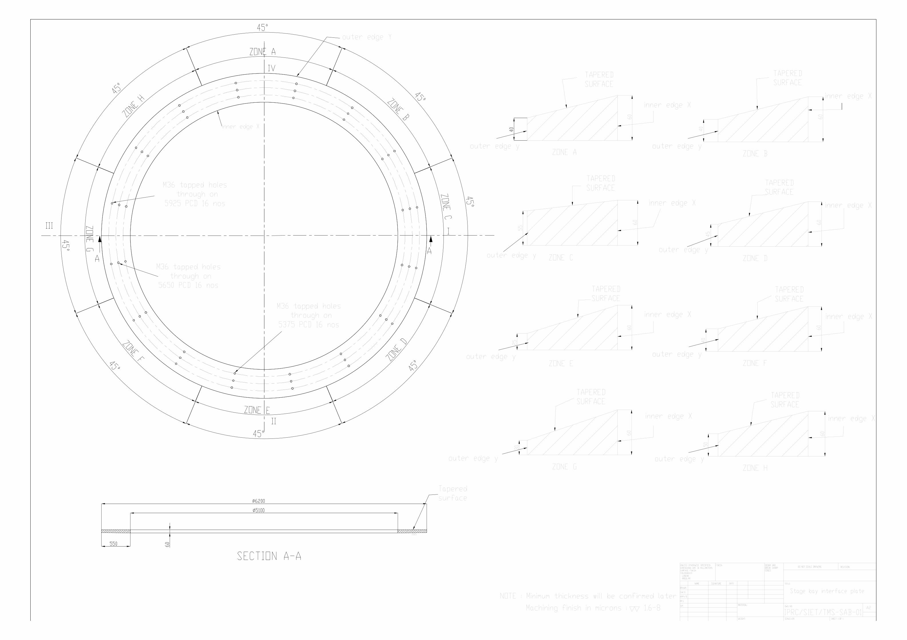
14. Stage Bay
Interface Plate
This interface plate is a separate structure similar to interface plate of TMS.
Stage Bay interface plate has to be fabricated and installed at the Stage Bay
Loading Frame.
3. Applicable codes and specifications
3.1. The items realized shall strictly comply with specifications, dimensions, tolerances given in
fabrication drawings of TMS issued by Department. Raw material requirements, fabrication &
inspection procedures and general tolerances shall be as per following standards / codes. All
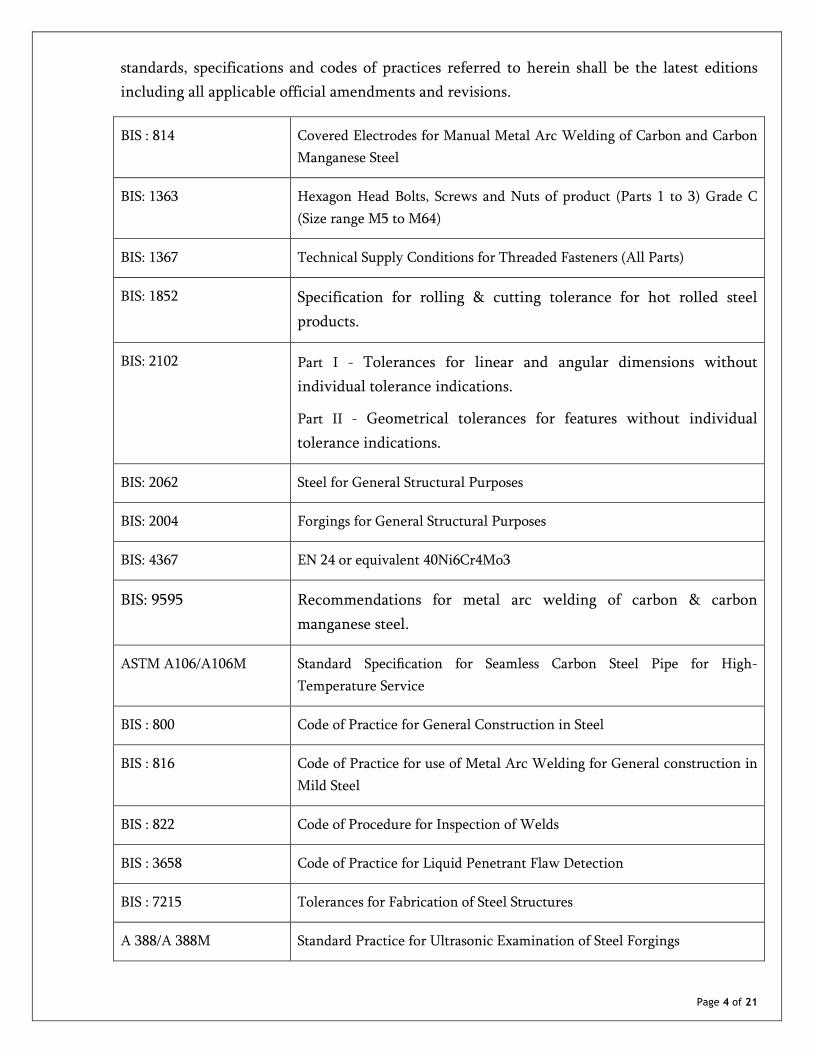
Page 4 of 21
standards, specifications and codes of practices referred to herein shall be the latest editions
including all applicable official amendments and revisions.
BIS : 814 Covered Electrodes for Manual Metal Arc Welding of Carbon and Carbon
Manganese Steel
BIS: 1363 Hexagon Head Bolts, Screws and Nuts of product (Parts 1 to 3) Grade C
(Size range M5 to M64)
BIS: 1367 Technical Supply Conditions for Threaded Fasteners (All Parts)
BIS: 1852 Specification for rolling & cutting tolerance for hot rolled steel
products.
BIS: 2102 Part I - Tolerances for linear and angular dimensions without
individual tolerance indications.
Part II - Geometrical tolerances for features without individual
tolerance indications.
BIS: 2062 Steel for General Structural Purposes
BIS: 2004 Forgings for General Structural Purposes
BIS: 4367 EN 24 or equivalent 40Ni6Cr4Mo3
BIS: 9595 Recommendations for metal arc welding of carbon & carbon
manganese steel.
ASTM A106/A106M Standard Specification for Seamless Carbon Steel Pipe for High-
Temperature Service
BIS : 800 Code of Practice for General Construction in Steel
BIS : 816 Code of Practice for use of Metal Arc Welding for General construction in
Mild Steel
BIS : 822 Code of Procedure for Inspection of Welds
BIS : 3658 Code of Practice for Liquid Penetrant Flaw Detection
BIS : 7215 Tolerances for Fabrication of Steel Structures
A 388/A 388M Standard Practice for Ultrasonic Examination of Steel Forgings

Page 5 of 21
ASME BPVC Section V
Article 2
Radiographic Examination
ASME BPVC Section V
Article 4
Ultrasonic Examination
ASME BPVC Section VIII
Div.1
Post Weld Heat Treatment
4. Items
The following lists covers major items to be realized by Bidder. Detailed list shall be as per TMS
drawings listed below and Annexures.
• IPRC-SIET-TMS-01/A1-2 Sheets
• IPRC-SIET-TMS-02/A1-1 Sheet
• IPRC-SIET-TMS-03/A1-1 Sheet
• IPRC-SIET-TMS-04/A1-1 Sheet
• IPRC-SIET-TMS-05/A1-1 Sheet
• IPRC-SIET-TMS-06/A1-1 Sheet
• IPRC-SIET-TMS-07/A1-1 Sheet
• IPRC-SIET-TMS-08/A1-1 Sheet
• IPRC-SIET-TMS-09/A1-1 Sheet
• IPRC-SIET-TMS-10/A1-1 Sheet
• IPRC-SIET-TMS-11/A1-1 Sheet
• Annexure-A : List of Fasteners
• Annexure-B : List of bought out items
S.NO DESCRIPTION MATERIAL QTY W.T (Kg)
1. SPACER FRAME IS : 2062
E250 1 1550
2. FIXED FRAME
IS 2062:E250,
IS 2004:20C8,
ASTM A106 GR.B
1 8315
3. THRUST FRAME
IS 2062:E250,
IS 2004:20C8,
ASTM A106 GR.B
1 7050
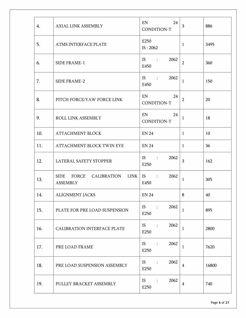
Page 6 of 21
4. AXIAL LINK ASSEMBLY EN 24
CONDITION-T 3 886
5. ATMS INTERFACE PLATE E250
IS : 2062 1 3495
6. SIDE FRAME-1 IS : 2062
E450 2 360
7. SIDE FRAME-2 IS : 2062
E450 1 150
8. PITCH FORCE/YAW FORCE LINK EN 24
CONDITION-T 2 20
9. ROLL LINK ASSEMBLY EN 24
CONDITION-T 1 18
10. ATTACHMENT BLOCK EN 24 1 10
11. ATTACHMENT BLOCK TWIN EYE EN 24 1 36
12. LATERAL SAFETY STOPPER IS : 2062
E250 3 162
13. SIDE FORCE CALIBRATION LINK
ASSEMBLY
IS : 2062
E450 1 305
14. ALIGNMENT JACKS EN 24 8 40
15. PLATE FOR PRE LOAD SUSPENSION IS : 2062
E250 1 895
16. CALIBRATION INTERFACE PLATE IS : 2062
E250 1 2800
17. PRE LOAD FRAME IS : 2062
E250 1 7620
18. PRE LOAD SUSPENSION ASSEMBLY IS : 2062
E250 4 16800
19. PULLEY BRACKET ASSEMBLY IS : 2062
E250 4 740

Page 7 of 21
20. CALIBRATION FRAME IS : 2062
E250 1 7175
21. 1000T HYDRAULIC JACK …….. 1 ……..
22. HYDRAULIC JACK ADAPTOR EN24 1 510
23. SPHERICAL BEARING &
BEARING HOUSING EN24 1 110
24. IN-SITU CALIBRATION LINK EN24 1 290
25. DUMMY LOAD CELLS EN 24
CONDITION-T 1 250
26. IN-SITU TIE ROD IS : 2062
E250 1 1280
27. WORKING PLATFORM IS : 2062
E250 1 830
28. CALIBRATION PLATE IS : 2062
E250/EN24 1 2865
29. SS 304L Cover IS : 2062
E250 1 1000
30. FASTENERS As per Annexure A LOT LOT
31. BOUGHTOUT ITEMS As per Annexure B LOT LOT
32. COMPONENTS FOR LOAD TESTING IS : 2062
E250 1 15550
33. STAGE BAY INTERFACE PLATE IS : 2062
E250 1 5500
5. Materials
All the materials shall comply with the specifications given in drawings. All materials used
shall be new, unused and free from any defect.
6. Fabrication
6.1. All workmanship and finish shall be of best quality and shall conform to the best method of
fabrication. All materials shall be finished straight and shall be machined/ground smooth true

Page 8 of 21
and square where so specified. All holes and edges shall be free of burrs. Shearing and chipping
shall be neatly and accurately done and all portions of work exposed to view shall be neatly
finished. Material at the shops shall be kept clean and protected from weather.
6.2. All materials shall be straight and, if necessary, before being worked shall be straightened
and/or flattened by pressure and shall be free from twists. Heating or forging shall not be
resorted to without the prior approval of the Department.
6.3. Welding procedure shall be submitted to Department for approval. Welding shall be entrusted
to only qualified and experienced welders who shall be periodically tested and graded as per
BIS 817, BIS: 7310 (Part 1) and BIS: 7318(Part 1). Welder Qualification Reports shall be
submitted to Department for approval. Approval of the welding procedure by the Department
shall not relieve the Bidder of his responsibility for correct and sound welding without undue
distortion in the finished structure.
6.4. Welding electrodes shall be kept in electric oven during welding process. Base metal shall be
preheated to the temperature as per relevant BIS codes.
6.5. Welding process shall be Shielded Metal Arc Welding or Flux Cored Arc Welding. Electrodes
shall be E7018 for IS2062 Materials. In case of welding in EN 24 material, suitable weld
electrodes are to be used. Special electrodes to be used for welding dissimilar materials after
obtaining approval from Department and the details of the same shall be incorporated in
Quality Assurance Plan (QAP).
6.6. The correction of defective welds shall be carried out as directed by the Department without
damaging the parent metal. When a crack in the weld is removed, magnetic particle inspection
or any other equally positive means as prescribed by the Department shall be used to ensure
that the whole of the crack and material up to 25 mm beyond each end of the crack has been
removed. Cost of all such tests and operations incidental to correction shall be to the Bidder's
account.
7. Stress Relieving:
7.1. Stress Relieving is to be done for the parts wherever heavy machining or heavy welding is
involved as indicated in Table-A. The Thrust Frame and Fixed Frame have to be stress relieved
individually as a whole part in a single heat treatment process. IPRC team will witness the
Stress Relieving process.
7.2. Heat Treatment shall be done using electric heater coils with complete thermal insulation in
place. Adequate number of temperature measurements shall be provided to monitor uniform
heating of structure throughout the process.
Page 9 of 21
7.3. The procedure for heat treatment, schematic drawing of heating arrangement, location of
temperature measurements planned, thermal insulation covering, etc. shall be submitted in
advance to IPRC for review and clearance. Before attempting heat treatment, a coupon level
test has to be carried out and process has to be verified.
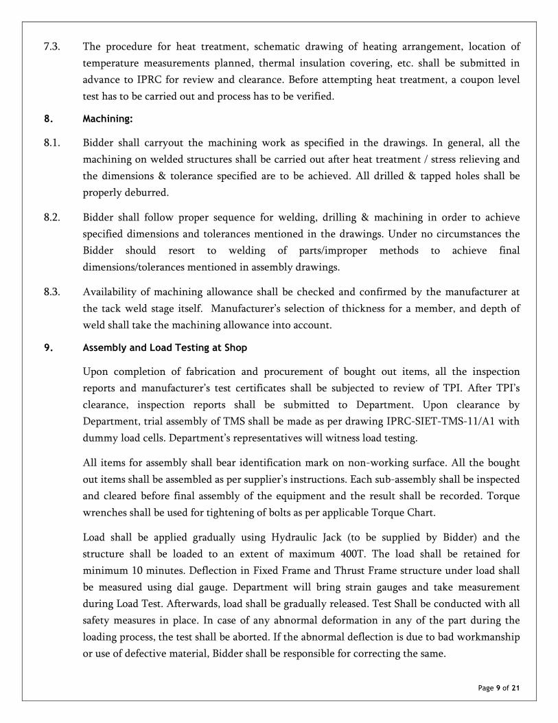
8. Machining:
8.1. Bidder shall carryout the machining work as specified in the drawings. In general, all the
machining on welded structures shall be carried out after heat treatment / stress relieving and
the dimensions & tolerance specified are to be achieved. All drilled & tapped holes shall be
properly deburred.
8.2. Bidder shall follow proper sequence for welding, drilling & machining in order to achieve
specified dimensions and tolerances mentioned in the drawings. Under no circumstances the
Bidder should resort to welding of parts/improper methods to achieve final
dimensions/tolerances mentioned in assembly drawings.
8.3. Availability of machining allowance shall be checked and confirmed by the manufacturer at
the tack weld stage itself. Manufacturer’s selection of thickness for a member, and depth of
weld shall take the machining allowance into account.
9. Assembly and Load Testing at Shop
Upon completion of fabrication and procurement of bought out items, all the inspection
reports and manufacturer’s test certificates shall be subjected to review of TPI. After TPI’s
clearance, inspection reports shall be submitted to Department. Upon clearance by
Department, trial assembly of TMS shall be made as per drawing IPRC-SIET-TMS-11/A1 with
dummy load cells. Department’s representatives will witness load testing.
All items for assembly shall bear identification mark on non-working surface. All the bought
out items shall be assembled as per supplier’s instructions. Each sub-assembly shall be inspected
and cleared before final assembly of the equipment and the result shall be recorded. Torque
wrenches shall be used for tightening of bolts as per applicable Torque Chart.
Load shall be applied gradually using Hydraulic Jack (to be supplied by Bidder) and the
structure shall be loaded to an extent of maximum 400T. The load shall be retained for
minimum 10 minutes. Deflection in Fixed Frame and Thrust Frame structure under load shall
be measured using dial gauge. Department will bring strain gauges and take measurement
during Load Test. Afterwards, load shall be gradually released. Test Shall be conducted with all
safety measures in place. In case of any abnormal deformation in any of the part during the
loading process, the test shall be aborted. If the abnormal deflection is due to bad workmanship
or use of defective material, Bidder shall be responsible for correcting the same.

Page 10 of 21
After completion of test, TMS assembly shall be dismantled and dimensions of all the
components shall be once again verified. Necessary match marking shall be carried out before
dismantling. Post Load Test inspection reports shall be submitted to Department for review.
Upon clearance by Department, painting works shall be carried out on the structure.
It may be necessary to dismantle sub-assembly or fully assembled item for packing and onward
forwarding to site. In such cases it shall be ensured that minimum numbers of parts are
dismantled and these parts bear match / identification marks to repeat same assembly during
erection.
10. Inspection
10.1. Detailed Quality Assurance Plan (QAP) is to be prepared by Bidder upon award of order clearly
identifying component wise stages of inspection and inspection roles of Bidder, Third Party
Inspector & Department. The QAP shall be submitted to the Department for review and
approval. Approved QAP shall be followed during the course of realization.
10.2. Bidder shall be responsible for inspection and quality control of TMS and related
documentation. In addition, Bidder shall employ a reputed Third Party Inspection (TPI) agency
throughout the work at shop and site. Bidder shall co-ordinate with TPI agency and carryout
inspection. TPI agencies such as Lloyds Register or Bureau Veritas or Det-Norske Veritas or
Technischer Uberwachungs Verein shall only be involved.
10.3. The stage inspections in shop shall include but not limited to the following:
Sl.No. Activity TPI’s role shall include
a. Raw material inspection Taking Sample * and Reviewing
test reports
b. Fit-up inspection Witnessing 100%
c. Root run inspection Witnessing 100%
d. Final welding inspection Witnessing 100%
e. Stress Relieving Witnessing 100%
f. Dimensional inspection Witnessing 100%
g. WPS, PQR and Welders certification as required Witnessing 100%
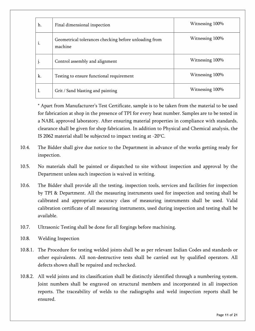
Page 11 of 21
h. Final dimensional inspection Witnessing 100%
i. Geometrical tolerances checking before unloading from
machine
Witnessing 100%
j. Control assembly and alignment Witnessing 100%
k. Testing to ensure functional requirement Witnessing 100%
l. Grit / Sand blasting and painting Witnessing 100%
* Apart from Manufacturer’s Test Certificate, sample is to be taken from the material to be used
for fabrication at shop in the presence of TPI for every heat number. Samples are to be tested in
a NABL approved laboratory. After ensuring material properties in compliance with standards,
clearance shall be given for shop fabrication. In addition to Physical and Chemical analysis, the
IS 2062 material shall be subjected to impact testing at -20°C.
10.4. The Bidder shall give due notice to the Department in advance of the works getting ready for
inspection.
10.5. No materials shall be painted or dispatched to site without inspection and approval by the
Department unless such inspection is waived in writing.
10.6. The Bidder shall provide all the testing, inspection tools, services and facilities for inspection
by TPI & Department. All the measuring instruments used for inspection and testing shall be
calibrated and appropriate accuracy class of measuring instruments shall be used. Valid
calibration certificate of all measuring instruments, used during inspection and testing shall be
available.
10.7. Ultrasonic Testing shall be done for all forgings before machining.
10.8. Welding Inspection
10.8.1. The Procedure for testing welded joints shall be as per relevant Indian Codes and standards or
other equivalents. All non-destructive tests shall be carried out by qualified operators. All
defects shown shall be repaired and rechecked.
10.8.2. All weld joints and its classification shall be distinctly identified through a numbering system.
Joint numbers shall be engraved on structural members and incorporated in all inspection
reports. The traceability of welds to the radiographs and weld inspection reports shall be
ensured.
Page 12 of 21
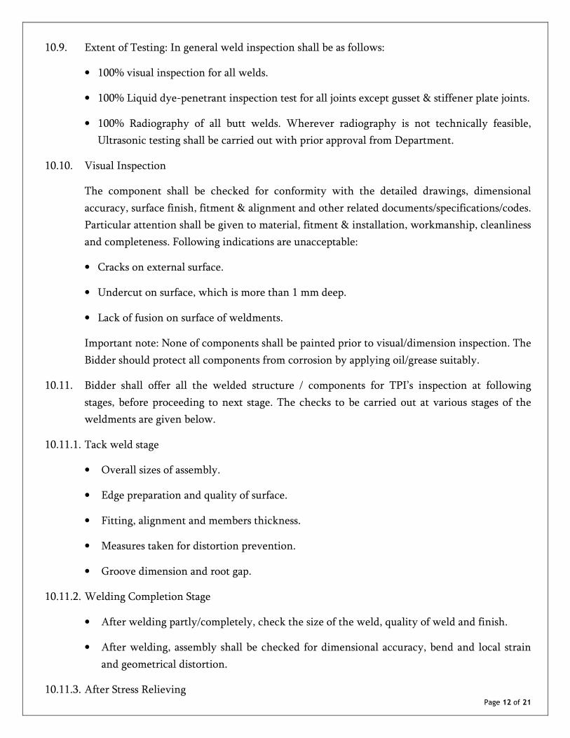
10.9. Extent of Testing: In general weld inspection shall be as follows:
• 100% visual inspection for all welds.
• 100% Liquid dye-penetrant inspection test for all joints except gusset & stiffener plate joints.
• 100% Radiography of all butt welds. Wherever radiography is not technically feasible,
Ultrasonic testing shall be carried out with prior approval from Department.
10.10. Visual Inspection
The component shall be checked for conformity with the detailed drawings, dimensional
accuracy, surface finish, fitment & alignment and other related documents/specifications/codes.
Particular attention shall be given to material, fitment & installation, workmanship, cleanliness
and completeness. Following indications are unacceptable:
• Cracks on external surface.
• Undercut on surface, which is more than 1 mm deep.
• Lack of fusion on surface of weldments.
Important note: None of components shall be painted prior to visual/dimension inspection. The
Bidder should protect all components from corrosion by applying oil/grease suitably.
10.11. Bidder shall offer all the welded structure / components for TPI’s inspection at following
stages, before proceeding to next stage. The checks to be carried out at various stages of the
weldments are given below.
10.11.1. Tack weld stage
• Overall sizes of assembly.
• Edge preparation and quality of surface.
• Fitting, alignment and members thickness.
• Measures taken for distortion prevention.
• Groove dimension and root gap.
10.11.2. Welding Completion Stage
• After welding partly/completely, check the size of the weld, quality of weld and finish.
• After welding, assembly shall be checked for dimensional accuracy, bend and local strain
and geometrical distortion.
10.11.3. After Stress Relieving

Page 13 of 21
• Dimensional inspection
• Freeness from heat treatment cracks.
• T-T Curve Chart of Heat Treatment.
10.12. Machining Inspection
All the components shall be machined as per the surface finish indicated in the drawings. Any
deviation on machined component from the drawing shall be brought to the notice of IPRC
immediately. Bidder shall not take any unilateral decision on his own in order to salvage the
item. Dimensional record to be maintained and sketches to be added as required.
After complete inspection of a component, a summary sheet shall be prepared and maintained.
All the necessary tools and instruments shall be arranged by the Bidder.
10.13. Painting and Inspection
10.13.1. TMS shall be painted as per the following scheme.
• Thrust Frame Assembly, Spacer Frame, Preload plates – Golden Yellow
• Fixed Frame Assembly, Preload Frame, Calibration Frame Assembly, Pulley blocks,
Interface frame, Side Frame Assembly-1 (2 nos.), and Side Frame Assembly-2, Calibration
side frame– Phirozi Blue
• All Tie rods, Attachment Blocks, Flexure Seating Plates, Cover plates, Safety Fixtures, Other
Load Test Fixtures - Black
10.13.2. Painting requirements shall be as follows
• Inorganic zinc silicate, DFT-100 microns (min) at shop floor
• Polyurethane, DFT – 100 microns (min) at shop floor
10.13.3. The following brands shall be used.
• GP Bond 141 of Grand Polycoats (Aliphatic polyurethane)
• 2. Bergerthane enamel of Berger (Acrylic polyurethane)
• Apcothane CF674 of Asian paint (Acrylic- Aliphatic polyurethane)
• Pentathane finish paint 4513 of Bombay Paints (Aliphatic isocyanate polyurethane)
10.13.4. Machined interfaces shall not be painted. However, protective coating (IS 158/ Rustex- 3C/
Black Japan) shall be applied immediately after machining to prevent corrosion.
Page 14 of 21
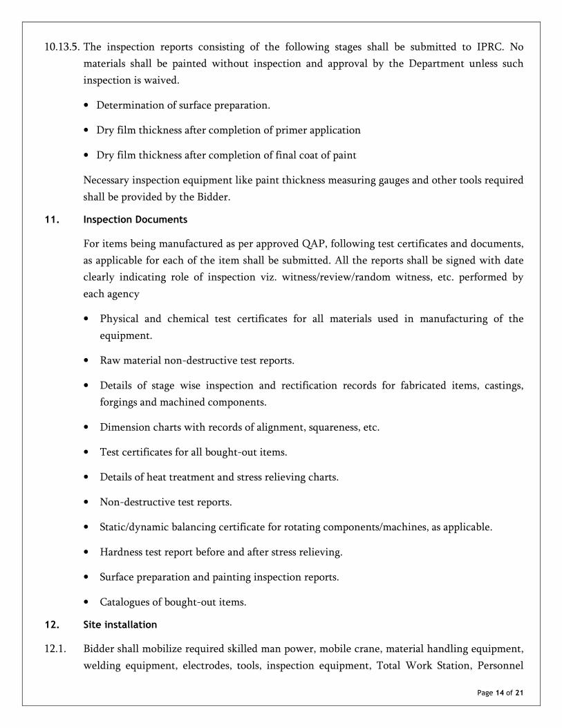
10.13.5. The inspection reports consisting of the following stages shall be submitted to IPRC. No
materials shall be painted without inspection and approval by the Department unless such
inspection is waived.
• Determination of surface preparation.
• Dry film thickness after completion of primer application
• Dry film thickness after completion of final coat of paint
Necessary inspection equipment like paint thickness measuring gauges and other tools required
shall be provided by the Bidder.
11. Inspection Documents
For items being manufactured as per approved QAP, following test certificates and documents,
as applicable for each of the item shall be submitted. All the reports shall be signed with date
clearly indicating role of inspection viz. witness/review/random witness, etc. performed by
each agency
• Physical and chemical test certificates for all materials used in manufacturing of the
equipment.
• Raw material non-destructive test reports.
• Details of stage wise inspection and rectification records for fabricated items, castings,
forgings and machined components.
• Dimension charts with records of alignment, squareness, etc.
• Test certificates for all bought-out items.
• Details of heat treatment and stress relieving charts.
• Non-destructive test reports.
• Static/dynamic balancing certificate for rotating components/machines, as applicable.
• Hardness test report before and after stress relieving.
• Surface preparation and painting inspection reports.
• Catalogues of bought-out items.
12. Site installation
12.1. Bidder shall mobilize required skilled man power, mobile crane, material handling equipment,
welding equipment, electrodes, tools, inspection equipment, Total Work Station, Personnel

Page 15 of 21
Protective Equipment, etc. for installation of TMS at site. Total Work Station shall be used to
measure level variation.
12.2. Upon delivery of required materials at site, Bidder shall commence site installation works. The
interface plates shall be welded to Engine Bay Loading Frame structure after leveling it with
the mating surface to the extent of ±1mm. In case of any mismatch, local grinding shall be done
to mate the surfaces. Welding shall be done by qualified welders in a controlled way. Upon
welding inspection and ensuring of weld quality, installation of TMS shall commence.
12.3. Assembly of TMS shall be made as per drawing IPRC-SIET-TMS-01/A1 (In-situ calibration
setup). All the bought out items shall be assembled as per supplier’s instructions. Each sub-
assembly shall be inspected and cleared before final assembly of the equipment and the result
shall be recorded. Torque wrenches shall be used for tightening of bolts as per standard Torque
Chart. Department will issue actual Load Cells of TMS to Bidder as Free Issue Material for
installation at site. Bidder shall assemble the same with TMS.
12.4. Upon assembly of TMS unit with Loading Frame Structure and clearance by Department,
Bidder shall carryout load testing at site. Load shall be applied gradually using Hydraulic Jack
and the structure shall be loaded to an extent of maximum 220T. The load shall be retained for
minimum 10 minutes. Afterwards, load shall be gradually released. Test shall be conducted
with all safety measures in place.
12.5. After successful load testing, the in-situ calibration setup shall be dismantled and preload set up
shall be assembled.
12.6. Removable type cover made of 5mm thick Stainless Steel 304L plate shall be provided by
Bidder to cover the complete Fixed Frame Structure of TMS after completion of all inspection
works after load testing.
12.7. The Stage Bay Interface Plate shall be welded to Stage Bay Loading Frame structure after
leveling it with the mating surface to the extent of ±1mm. Welding shall be done by qualified
welders in a controlled way. Upon welding inspection and ensuring of weld quality.
12.8. At site, the test stand structure is equipped with an EOT crane of capacity 10t and working
level platforms are available at 11.5m level & 16 m level. Bidder shall arrange any further
temporary structure required for installing / inspecting TMS at site.
12.9. All the site works shall also be monitored and inspected by TPI agency.
13. General Instructions to Bidder
13.1. Bidder shall quote for entire scope of work as per the specific invitation to tender. If any part of
scope is excluded from his offer, the quotation of the Bidder will be liable to get rejected.
Page 16 of 21
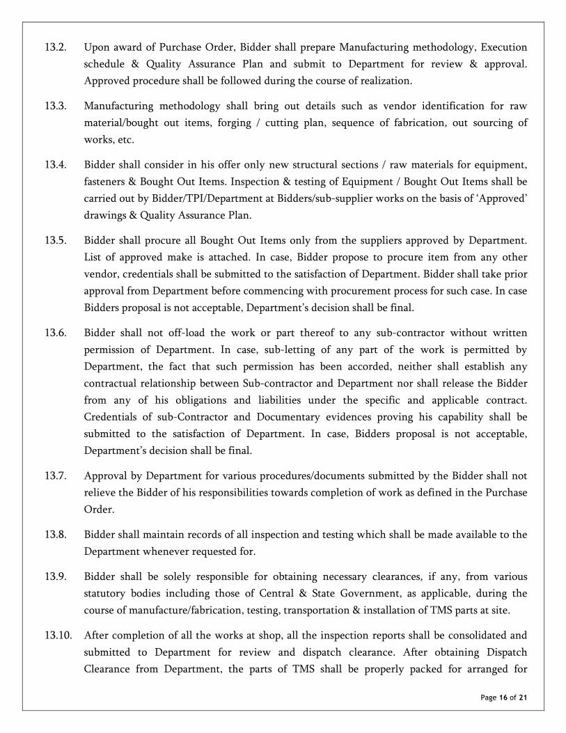
13.2. Upon award of Purchase Order, Bidder shall prepare Manufacturing methodology, Execution
schedule & Quality Assurance Plan and submit to Department for review & approval.
Approved procedure shall be followed during the course of realization.
13.3. Manufacturing methodology shall bring out details such as vendor identification for raw
material/bought out items, forging / cutting plan, sequence of fabrication, out sourcing of
works, etc.
13.4. Bidder shall consider in his offer only new structural sections / raw materials for equipment,
fasteners & Bought Out Items. Inspection & testing of Equipment / Bought Out Items shall be
carried out by Bidder/TPI/Department at Bidders/sub-supplier works on the basis of ‘Approved’
drawings & Quality Assurance Plan.
13.5. Bidder shall procure all Bought Out Items only from the suppliers approved by Department.
List of approved make is attached. In case, Bidder propose to procure item from any other
vendor, credentials shall be submitted to the satisfaction of Department. Bidder shall take prior
approval from Department before commencing with procurement process for such case. In case
Bidders proposal is not acceptable, Department’s decision shall be final.
13.6. Bidder shall not off-load the work or part thereof to any sub-contractor without written
permission of Department. In case, sub-letting of any part of the work is permitted by
Department, the fact that such permission has been accorded, neither shall establish any
contractual relationship between Sub-contractor and Department nor shall release the Bidder
from any of his obligations and liabilities under the specific and applicable contract.
Credentials of sub-Contractor and Documentary evidences proving his capability shall be
submitted to the satisfaction of Department. In case, Bidders proposal is not acceptable,
Department’s decision shall be final.
13.7. Approval by Department for various procedures/documents submitted by the Bidder shall not
relieve the Bidder of his responsibilities towards completion of work as defined in the Purchase
Order.
13.8. Bidder shall maintain records of all inspection and testing which shall be made available to the
Department whenever requested for.
13.9. Bidder shall be solely responsible for obtaining necessary clearances, if any, from various
statutory bodies including those of Central & State Government, as applicable, during the
course of manufacture/fabrication, testing, transportation & installation of TMS parts at site.
13.10. After completion of all the works at shop, all the inspection reports shall be consolidated and
submitted to Department for review and dispatch clearance. After obtaining Dispatch
Clearance from Department, the parts of TMS shall be properly packed for arranged for

Page 17 of 21
transportation. Suitable support fixtures are to be used while loading the items in the
transportation trailer to avoid any damage to the system during transportation.
13.11. Bidder shall furnish the supplier’s Installation, Operation and Maintenance Manual for all the
Bought Out Items.
13.12. Location of site:
Mahendragiri is situated in Tirunelveli district, Tamil Nadu state, India. The nearest major
towns are Nagercoil, which is 25 km southward and Valliyur, which is 15 km northward.
IPRC, Mahendragiri is aside of Kanyakumari-Madurai National Highway (NH7) at a distance of
25 km Northward from Kanyakumari. The nearest major railway station is at Nagercoil. The
nearest international airport is at Thiruvananthapuram (Trivandrum, in Kerala state), which is
90 km away in South-West direction.
The installation site in Mahendragiri is about ≈7 km from gate and it is connected with an
approach road of 5.5m wide. The climatic condition at Mahendragiri is tropical and windy with
gusts.
14. Instructions for Unloading, Safe Storage of items and Site installation
14.1. Bidder shall mobilize all the required items and manpower to site with proper permission from
Department and shall maintain proper records.
14.2. Bidder shall make own arrangement for receiving items at site including Crane, slings,
shackles, tools, etc. for unloading items at site. Department will provide open yard for storing
the items. Bidder shall be responsible for safe storage and custody of items.
14.3. At site other erection works are also progressing. Bidder has to work in parallel with necessary
safety measures and complete the work.
14.4. Normal working time is between 09:00 Hours to 17:00 Hours on working days. If Bidder has to
work beyond normal working hours or on holidays for completing the work on schedule, prior
permission from Department needs to be obtained by Bidder. The Bidder’s personnel shall not
be permitted to reside inside the Department’s premises after the work.
14.5. Bidder shall make their own arrangement for transportation, accommodation, food, health
care, communication, etc. for their personnel.
14.6. Bidder shall make his own arrangement to safeguard his items. Department will not be
responsible for damage or loss of any items of Bidder.
14.7. Department will issue Load Cells to Bidder as Free Issue Material for installation at site. Bidder
shall be responsible for the safe custody of Load Cells till final acceptance of TMS by
Department.
Page 18 of 21
14.8. Bidder shall be responsible for the safety of persons deployed to site and shall insure all persons
working at site. Department will not be responsible for any type of accident caused to the
Bidder’s personnel.
14.9. During the execution of the work, if Bidder cause any damage to Department property in any
form, necessary charges for repair / replacement of the same will be recovered from Bidder by
Department.
14.10. Bidder shall abide the statutory rules, laws, acts like minimum wages, Labor license,
insurance/ESI, GST, Income Tax, etc. applicable as per Government of India/Government of
Tamil Nadu in force during work execution.
15. Guarantee
Bidder shall submit a Guarantee Certificate for the items supplied for a period of 12 months
from the date of final acceptance of system at our site against fabrication, manufacturing and
workmanship defects. In case any defect develops in the work due to bad material and / or bad
workmanship before the expiry of guarantee period, the Bidder, on notification by
Department, shall rectify or remedy the defect at their own cost and shall make their own
arrangements to provide materials, labour, equipment and any other appliances required in this
regard.
16. Execution Schedule
All the items shall be supplied and installed at site within 7 months from the date of purchase
order. Upon placement of order, Bidder shall submit a detail schedule of all activities involved
to complete the whole work within the delivery period in the form of Gantt chart. The agreed
Gantt chart shall be the basis for progress monitoring and corrective measures during the
execution period. The successful Bidder shall furnish monthly progress reports.
17. Security Deposit
The Bidder shall submit Security Deposit in the form of an unconditional bank guarantee from
any nationalized/scheduled bank approved by RBI for 10% of the Contract value to the
Department within 30 days upon award of contract. This deposit is meant to compensate, the
department, for any loss due to failure of the supplier to complete his obligations as per the
purchase order. The Security Deposit shall be valid for a period of 60 days beyond the date of
final acceptance of the system.
18. Liquidated Damages
Due to reasons not attributable to Department, if the Bidder fails to complete the work or fails
to meet delivery date within the time specified in the Purchase Order or any extension thereof,
the Department will recover liquidated damages (LD) from the Bidder a sum of 0.5% of the

Page 19 of 21
total order value for each calendar week of delay or part thereof. The total value of liquidated
damages shall not exceed 10% of the order value.
19. Force Majeure
Neither party shall bear responsibility for the complete or partial non-performance of any of
his obligations (except for failure to pay any sum which has become due on account of receipt
of goods under the provisions of the order) if the non-performance results from such force
majeure circumstances such as, but not restricted to, flood, fire, earthquake, civil commotion,
sabotage, explosion, epidemic, quarantine restriction, strike, lock-out, freight embargo, acts of
the Government either in its sovereign or Contractual capacity, hostility, acts of public enemy
and other acts of God as well as war or revolution, military operation, blockade, acts or actions
of State authorities or any other circumstance beyond the control of the parties that have
arisen after the conclusion of the order. In such circumstances, the time stipulated for the
performance of an obligation under the order may be proportionately extended.
The party, for whom it has become impossible to meet the obligation under order due to force
majeure condition, will notify the other party in writing not later than twenty-one days from
the date of commencement of the unforeseeable event. Unless otherwise directed by the
department in writing, the Bidder shall continue to perform his obligations under order as far
as is practical and shall seek all reasonable alternative means for performance not prevented by
the force majeure event.
Any certificate issued by the Chamber of Commerce or any other competent authority or
organization of the respective country shall be sufficient proof of commencement and cessation
of the above circumstances.
In case of failure to carry out complete or partial performance of an obligation for more than
sixty days, either party shall reserve the right to terminate the order totally or partially. A prior
written notice of 30 days to the other party will be given informing of the intention to
terminate without any liability. This is exclusive of any reimbursements for the goods received
as provided for in the agreement.
20. Payment
20.1. Bidder shall understand the complete scope of work and quote firm and fixed lump sum price
for executing entire scope of work as per terms & conditions specified in the tender.
20.2. No extra claim shall be entertained from the Bidder, if the actual weight fabricated differ from
those indicated in drawings.
20.3. In case of any additional quantity or work requested by Department to meet any additional
requirement in connection with functional/safety of Thrust Measurement System, Bidder shall

Page 20 of 21
execute the same without holding the work. After completion of entire scope of work,
Department & Bidder shall discuss and mutually arrive at the price for such additional
quantity/work performed.
20.4. Department shall reimburse all taxes as per the prevailing rates at actuals.
20.5. Department is entitled for concessional GST @ 5% (for material supply) as per Ministry of
Finance, Department of Revenue, Notification No. 45/2017-Central Tax (Rate) and 47/2017-
Integrated Tax (Rate) dated 14.11.2017. Department will issue necessary concessional GST
certificate for claiming Concessional GST in favor of Bidder & Vendor only for items directly
consigned to Department. It is the responsibility of Bidder to obtain concessional certificates
from Department by providing necessary details & documents well in advance.
20.6. Department will issue Custom Duty Exemption Certificate for the imported items covered
under Customs Notification No. 5/2018 dated 25.01.2018 and directly consigned to
Department. It is the responsibility of Bidder to obtain concessional certificates from
Department by providing necessary details & documents well in advance.
20.7. Milestone Payment shall be considered as follows:
20.7.1. Upon placement of order and Acceptance of Manufacturing Methodology & Quality Assurance
Plan by Department: 20% of order value shall be paid against bank guarantee (valid for
complete delivery period) and submission of proforma invoice.
20.7.2. Upon completion of delivery of all the items to site: 60% of order value shall be paid against
proforma invoice and delivery documents.
20.7.3. Upon completion of site installation & load testing: 20% of order value shall be paid against
satisfactory completion of site installation of all the TMS unit and successful load testing of
TMS at site and submission of performance bank guarantee for 10% of order value (valid for 12
months from the date of final acceptance of the system by Department) & proforma invoice.
All bank guarantees shall be unconditional and issued by any nationalized/scheduled bank
approved by RBI.
21. Pre-Qualification criteria
The Bidder’s capability will be evaluated based on the following Pre-Qualification (PQ)
criteria. The Bidders shall suitably submit the information solicited and submit as part of the
Techno-Commercial Bid along with supporting documentary evidences. Those Bidders who
fulfil PQ criteria only will be screened-in for opening and evaluation of Price Bid. Any lack of
information or incomplete information or information non-compliant with the PQ criteria
shall be treated as sufficient cause to summarily reject such Bids.
Page 21 of 21
21.1. Average annual financial turnover of Bidder during the last 3 years, ending 31/03/2018, shall be
at least Rs.135 Lakhs. Audited annual turnover document for the last 3 years shall be
submitted.
21.2. The Bidder must have successfully supplied an Equipment or Structure of size minimum 2.5m
in diameter or 2.5mx2.5m in size with parts of minimum thickness 140 mm involving
machining in the last 7 years period ending 31/12/2018. Bidder shall submit the following
documentary evidences:
21.2.1. Purchase order and corresponding acceptance certificate from client
21.2.2. A technical note on brief description of the item highlighting details such as
• Size of the item
• Thickness of the machined parts
• Machining tolerance
• Drawings / sketches / photographs
21.3. The Bidder must have successfully completed supply of items for the following Purchase order
values during the last 5 years ending 31/12/2018. Bidder shall submit purchase order and
corresponding acceptance certificate from client as documentary evidence.
21.3.1. One work of Purchase Order value equal to or more than Rs. 360 Lakhs
Or
21.3.2. Two works each Purchase Order of value equal to or more than Rs. 225 Lakhs
Or
21.3.3. Three works each Purchase Order of value equal to or more than Rs. 180 Lakhs
22. Bid Details
22.1. Bid shall be submitted in Two Parts viz. Techno-Commercial Offer and Price Offer
22.2. Bidder shall not mention or indicate any element of price whatsoever, as sum or percentage, in
the Techno-commercial bid. Such information is to be given in the Price bid only. Bid will be
summarily rejected, if Bidder mention any information on price in Techno-Commercial bid.
22.3. Offer Validity: Offer shall be valid for a minimum period of six months from tender due date.
22.4. Delivery term: The items shall be transported, unloaded at Department’s site in IPRC,
Mahendragiri, Tirunelveli and installed at site.
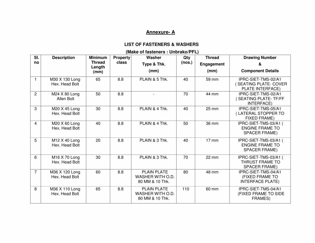
Annexure- A
LIST OF FASTENERS & WASHERS
(Make of fasteners : Unbrako/PFL)
Sl. no
Description Minimum Thread Length (mm)
Property class
Washer
Type & Thk.
(mm)
Qty (nos.)
Thread
Engagement
(mm)
Drawing Number
&
Component Details
1 M30 X 130 Long Hex. Head Bolt
65 8.8 PLAIN & 5 Thk. 40 59 mm IPRC-SIET-TMS-02/A1 ( SEATING PLATE- COVER
PLATE INTERFACE)
2 M24 X 80 Long Allen Bolt
50 8.8 - 70 44 mm IPRC-SIET-TMS-02/A1 ( SEATING PLATE- TF/FF
INTERFACE)
3 M20 X 45 Long Hex. Head Bolt
30 8.8 PLAIN & 4 Thk. 40 25 mm IPRC-SIET-TMS-05/A1 ( LATERAL STOPPER TO
FIXED FRAME)
4 M20 X 60 Long Hex. Head Bolt
40 8.8 PLAIN & 4 Thk. 50 36 mm IPRC-SIET-TMS-03/A1 ( ENGINE FRAME TO SPACER FRAME)
5 M12 X 40 Long Hex. Head Bolt
20 8.8 PLAIN & 3 Thk. 40 17 mm IPRC-SIET-TMS-03/A1 ( ENGINE FRAME TO SPACER FRAME)
6 M16 X 70 Long Hex. Head Bolt
30 8.8 PLAIN & 3 Thk. 70 22 mm IPRC-SIET-TMS-03/A1 ( THRUST FRAME TO
SPACER FRAME)
7 M36 X 120 Long Hex. Head Bolt
60 8.8 PLAIN PLATE WASHER WITH O.D.
80 MM & 10 Thk.
80 48 mm IPRC-SIET-TMS-04/A1 (FIXED FRAME TO
INTERFACE PLATE)
8 M36 X 110 Long Hex. Head Bolt
65 8.8 PLAIN PLATE WASHER WITH O.D.
80 MM & 10 Thk.
110 60 mm IPRC-SIET-TMS-04/A1 (FIXED FRAME TO SIDE
FRAMES)

9 M20 X 80 Long Hex. Head Bolt
45 8.8 PLAIN & 4 Thk. 40 36 mm IPRC-SIET-TMS-05/A1 ( CALIBRATION INTERFACE PLATE TO THRUST FRAME)
10 M24 X 90 Long Hex. Head Bolt
60 8.8 PLAIN & 4 Thk. 25 46 mm IPRC-SIET-TMS-07/A1 ( SIDE CALIBRATION FRAME
TO JACK BASE PLATE)
11 M24 X 70 Long Hex. Head Bolt
50 8.8 PLAIN & 4 Thk. 35 32 mm IPRC-SIET-TMS-08/A1 ( PULLY BLOCK TO PRELOAD FRAME)
12 M8 X 20 Long ALLEN Bolt
FULL THREAD
8.8 - 35 14 mm IPRC-SIET-TMS-08/A1 ( PULLY HOUSING
ASSEMBLY)
13 M36 X 100 Long Hex. Head Bolt
40 8.8 PLAIN PLATE WASHER WITH O.D.
80 MM & 6 Thk.
70 34 mm IPRC-SIET-TMS-08/A1 (PRELOAD FRAME TO INTERFACE PLATES)
14 M36 X 100 Long Hex. Head Bolt
40 8.8 PLAIN PLATE WASHER WITH O.D.
80 MM & 10 Thk.
70 34 mm IPRC-SIET-TMS-09/A1 (CALIBRATION FRAME TO
INTERFACE PLATES)
15 M16 X 60 Long Hex. Head Bolt
FULL THREAD
8.8 PLAIN & 5 Thk. 70 5 mm IPRC-SIET-TMS-09/A1 (CALIBRATION FRAME TO
WORKING PLATFORM)
16 M 48 X 180 Long Hex. Head Bolt
100
8.8 PLAIN PLATE WASHER WITH O.D.
80 MM & 10 Thk.
20 70 mm IPRC-SIET-TMS-09/A1 (CALIBRATION FRAME TO
1000 T JACK)
17 M20 X 140 Long Hex. Head Bolt
50 8.8 PLAIN & 5 Thk. 35 35 mm IPRC-SIET-TMS-09/A1 ( CALIBRATION PLATE TO
SPACER FRAME)
18 M24 X 80 Long Hex. Head Bolt
50 8.8 PLAIN & 5 Thk. 20 44 mm IPRC-SIET-TMS-09/A1 ( ENGINE SPACER FRAME)
19 M36 X 180 Long Hex. Head Bolt
60 10.9 SPHERICAL WASHER SET & 10
Thk.
25 50 mm IPRC-SIET-TMS-09/A1 (JACK ADAPRTOR TO BEARING HOUSING)
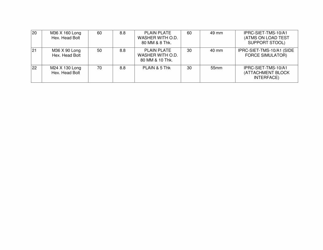
20 M36 X 160 Long Hex. Head Bolt
60 8.8 PLAIN PLATE WASHER WITH O.D.
80 MM & 8 Thk.
60 49 mm IPRC-SIET-TMS-10/A1 (ATMS ON LOAD TEST
SUPPORT STOOL)
21 M36 X 90 Long Hex. Head Bolt
50 8.8 PLAIN PLATE WASHER WITH O.D.
80 MM & 10 Thk.
30 40 mm IPRC-SIET-TMS-10/A1 (SIDE FORCE SIMULATOR)
22 M24 X 130 Long Hex. Head Bolt
70 8.8 PLAIN & 5 Thk 30 55mm IPRC-SIET-TMS-10/A1 (ATTACHMENT BLOCK
INTERFACE)

Page 1 of 9
Annexure-B
LIST OF BOUGHT-OUT ITEMS
Item No: 1
Maintenance-free Rod ends, Make: INA/SKF/FAG/LUK
(Drawing no: IPRC-SIET-TMS-07/A1)
Size Static
Load
Rating
Max.
swiveling
angle
Thread type Quantity
(including
spare)
Φ50 Pin 313 kN 6⁰ Right Hand Thread 4
Φ50 Pin 313 kN 6⁰ Left Hand Thread 4
Φ60 Pin 485 kN 6⁰ Right Hand Thread 4
Φ60 Pin 485 kN 6⁰ Left Hand Thread 4
Φ80 Pin 689 kN 6⁰ Right Hand Thread 2
*Φ35 Pin 159 kN 6⁰ Right Hand Thread 4
*Φ35 Pin 689 kN 6⁰ Left Hand Thread 4
Total 26
* Indicates spare bearings and not shown in drawings and to be supplied with
M36X3 female threads.
(Note: The thread size and other dimensions shall match with the load link as per the
respective drawings provided)
Item No: 2
Maintenance-free Axial Spherical plain bearings, Make: INA/SKF/FAG/LUK (Drawing
no: IPRC-SIET-TMS-09/A1)
� Capacity : 7100 kN (Static load rating)
� Shaft Diameter : 200 mm
� Overall Height : 87 mm
� Shaft Misalignment : ± 80
� Sliding contact surface : Hard chromium/PTFE fabric.
� Total quantity required : 03
Item No: 3
Double Acting Hydraulic Cylinders of Make: Larzep / Powerteam / Holmatro/ Enerpac/ Europress
(Drawing nos: IPRC-SIET-TMS-09/A1, IPRC-SIET-TMS-07/A1, IPRC-SIET-TMS-05/A1)
Axial calibration link:
� Max. Capacity : 985 t (Pull)
� Stoke length : 150 mm

Page 2 of 9
� Fully closed Height : 735 mm
� Operating pressure : 700 bar (maximum) with safety relief valve
� End fittings for hose : 3/8’’ NPTF and QC/DC as per standard.
� Quantity required : 01
� One spare kit consisting of O-rings & oil seals shall be provided for the jack.
Side force simulation link:
� Capacity : 44 t (pull)
� Stoke length : 330 mm
� Fully closed Height : 517.5 mm
� Operating pressure : 720 bar (Maximum) with built in safety relief valve.
� Thread in Jack Housing : 5 3/4” - 40 mm Long
� Mounting Thread on
Plunger Head
: 2 – 4 1/2”
� End fittings for hose : 3/8’’ NPTF and QC/DC as per standard.
� Total quantity required : 05
� One spare kit consisting of O-rings & oil seals shall be provided for each jack (Total- 3 nos).
Hydraulic hoses:
� Hoses : 10 m length hydraulic hose (700 bar) with QC/DC End
Fittings
� Quantity : 8 nos.
Tilt saddles:
� Make : Power Team
� Part no : 351325
� Quantity : 12 nos.
Pump:
� Make : Power team/ Larzep/ Enerpac/ Holmatro/ Europress
� Description : Manual ( 2 no.) suiting to 44t jack with two way
direction control valve (2 no.) and pressure reducing
valve (4 nos.)
� Type: : Eletrically operated ( 1 no.) suiting to 1000 t jack with
two way direction control valve (1 no.) and pressure
reducing valve (2nos.)
Oil
� Standard hydraulic oil ASTM Grade 215. Quantity : 200 Litres / 1 barrel.
Note:
� The thread size and other dimensions shall match with the load link as per the respective drawings provided
� Suitable handling provision shall be available for all the jacks.
� All the above items are to be procured from authorized distributors only and to be supplied with necessary load test/ warranty certificates.

Page 3 of 9
Item No: 4
Cylindrical bearings for pre-load pulley block, Make: INA/SKF/FAG/LUK (Drawing
no: IPRC-SIET-TMS-08/A1)
� Capacity : 75 kN (Static load rating)
� Shaft Diameter : 30 mm
� Overall Diameter : 72 mm
� Contact surface : Cylindrical rollers.
� Total quantity required : 06 nos.
Item No: 5
12t Capacity two Legged Wire Rope (Conforming to IS 2762: Wire Rope Slings and Sling Legs)
� Wire Rope Make : Usha Martin
� Wire Rope Specification : 6 x 37 steel core (CWR) with grade 1960 (as per IS 2266)
� Wire Rope diameter : 24 mm � Type : Mechanically spliced Two-leg wire rope slings with main ring at one end, ordinary thimbles at other.
� Lifting Capacity : 12 t � Effective Length : 6 m � Ferrule : Conforming to IS 10942 � Master Links (Ring) : Conforming to IS 2760. � Total quantity required : 02 sets.
Item No:6
10t Capacity four Legged Wire Rope (Conforming to IS 2762: Wire Rope Slings and Sling Legs) � Wire Rope Make : Usha Martin � Wire Rope Specification : 6 x 37 steel core (CWR) with grade 1960 (as per IS 2266)
� Wire Rope diameter : 16 mm � Type : Mechanically spliced four-leg wire rope slings with one main ring and two intermediate rings at one end, ordinary thimbles at other.
� Lifting Capacity : 10 t � Effective Length : 6 m � Ferrule : Conforming to IS 10942 � Master Links (Ring) : Conforming to IS 2760. � Total quantity required : 01 set.
Page 4 of 9
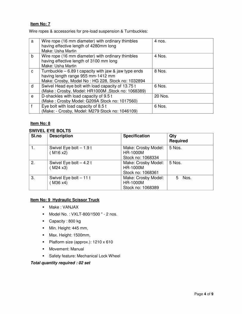
Item No: 7
Wire ropes & accessories for pre-load suspension & Turnbuckles:
a Wire rope (16 mm diameter) with ordinary thimbles having effective length of 4280mm long Make: Usha Martin
4 nos.
b Wire rope (16 mm diameter) with ordinary thimbles having effective length of 3100 mm long Make: Usha Martin
4 Nos.
c Turnbuckle – 6.89 t capacity with jaw & jaw type ends having length range 955 mm-1412 mm Make: Crosby, Model No : HG 228, Stock no: 1032894
8 Nos.
d Swivel Head eye bolt with load capacity of 13.75 t (Make : Crosby, Model: HR1000M ,Stock no: 1068389)
6 Nos.
e D-shackles with load capacity of 9.5 t (Make : Crosby Model: G209A Stock no: 1017560)
20 Nos.
f Eye bolt with load capacity of 8.5 t (Make: - Crosby, Model: M279 Stock no: 1046109)
6 Nos.
Item No: 8
SWIVEL EYE BOLTS Sl.no Description Specification Qty
Required
1. Swivel Eye bolt – 1.9 t ( M16 x2)
Make: Crosby Model: HR-1000M Stock no: 1068334
5 Nos.
2. Swivel Eye bolt – 4.2 t ( M24 x3)
Make: Crosby Model: HR-1000M Stock no: 1068361
5 Nos.
3. Swivel Eye bolt – 11 t ( M36 x4)
Make: Crosby Model: HR-1000M Stock no: 1068389
5 Nos.
Item No: 9 Hydraulic Scissor Truck
� Make : VANJAX
� Model No. : VXLT-800/1500 " - 2 nos.
� Capacity : 800 kg
� Min. Height: 445 mm,
� Max. Height: 1500mm,
� Platform size (approx.): 1210 x 610
� Movement: Manual
� Safety feature: Mechanical Lock Wheel
Total quantity required : 02 set
Page 5 of 9
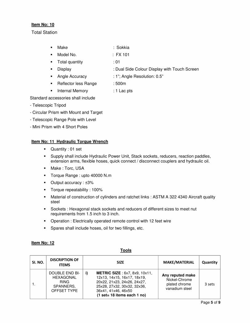
Item No: 10
Total Station
� Make : Sokkia
� Model No. : FX 101
� Total quantity : 01
� Display : Dual Side Colour Display with Touch Screen
� Angle Accuracy : 1”; Angle Resolution: 0.5”
� Reflector less Range : 500m
� Internal Memory : 1 Lac pts
Standard accessories shall include
- Telescopic Tripod
- Circular Prism with Mount and Target
- Telescopic Range Pole with Level
- Mini Prism with 4 Short Poles
Item No: 11 Hydraulic Torque Wrench
� Quantity : 01 set
� Supply shall include Hydraulic Power Unit, Stack sockets, reducers, reaction paddles, extension arms, flexible hoses, quick connect / disconnect couplers and hydraulic oil.
� Make : Torc, USA
� Torque Range : upto 40000 N.m
� Output accuracy : ±3%
� Torque repeatability : 100%
� Material of construction of cylinders and ratchet links : ASTM A 322 4340 Aircraft quality steel
� Sockets : Hexagonal stack sockets and reducers of different sizes to meet nut requirements from 1.5 inch to 3 inch.
� Operation : Electrically operated remote control with 12 feet wire
� Spares shall include hoses, oil for two fillings, etc.
Item No: 12
Tools
SI. NO. DISCRIPTION OF
ITEMS SIZE MAKE/MATERIAL Quantity
1.
DOUBLE END BI-HEXAGONAL
RING SPANNERS,
OFFSET TYPE
i) METRIC SIZE : 6x7, 8x9, 10x11, 12x13, 14x15, 16x17, 18x19, 20x22, 21x23, 24x26, 24x27, 25x28, 27x32, 30x32, 32x36, 36x41, 41x46, 46x50
(1 set= 18 items each 1 no)
Any reputed make Nickel-Chrome plated chrome vanadium steel
3 sets
Page 6 of 9
ii) METRIC SIZE: 34x38, 55x60, 75x80 (1 set= 3 items each 1 no)
3 sets
2. SINGLE END OPEN JAW SPANNER
i) METRIC SIZE : 55mm , 56mm, 58mm, 60mm, 66mm, 70mm, 75mm, 80mm, 120mm, 124mm
(1 set= 10 items each 1 no)
Any reputed make Nickel-Chrome plated chrome vanadium steel
3 sets
ii) METRIC SIZE: 95mm, 105mm (1 set= 2 items each 1 no)
3 sets
3. ADJUSTABLE SPANNERS
Span: 0-13mm length: 100mm Any reputed make
Nickel-Chrome plated chrome vanadium steel
3 Nos.
Span: 0-25 mm Length: 200mm
3 Nos.
Span: 0-36 mm Length: 250mm
3 Nos.
4.
SPANNERS OF ONE END WITH
JAW AND OTHER END WITH RING
i) METRIC SIZE: 10mm, 11mm, 12mm, 13mm, 14mm, 15mm, 16mm, 17mm, 18mm, 19mm, 20mm, 21mm, 22mm, 23mm, 24mm, 25mm, 26mm, 27mm, 28mm, 29mm, 30mm, 32mm, (1 set= 22 items each 1 no)
Any reputed make Nickel-Chrome plated chrome vanadium steel
3 sets
i) METRIC SIZE: 55mm, 60mm, 75mm, 80mm (1 set= 4 items each 1 no)
3 sets
5.
BOX SPANNER WITH
REVERSIBLE RATCHET with ½” square drive and 2 Nos. of ½” F X ¾”
M adapter
METRIC SIZE: 6mm, 7mm, 8mm, 9mm, 10mm, 11mm, 12mm, 13mm, 14mm, 15mm, 16mm, 17mm, 18mm, 19mm, 20mm, 21mm, 22mm, 23mm, 24mm, 25mm, 26mm, 27mm, 28mm, 29mm, 30mm, 31mm, 32mm, 34mm, 36mm,
41mm, 50mm (1 set= 31 items each 1 no)
Any reputed make Manufacturer’s
standard material 3 sets
6.
TORQUE WRENCH WITH ½” square drive
with 2 Nos. of ½” F X ¾” M adapter
RANGE: 14-68 Nm
Any reputed make Manufacturer’s
standard material
3 Nos.
RANGE: 25-135 Nm 3 Nos.
RANGE: 50-220 Nm 3 Nos.
RANGE: 135-540 Nm 3 Nos.
RANGE: 475-1015 Nm 3 Nos.
7.
OPEN ENDS, ROUND
ATTACHEMENT (TO SUIT ABOVE
TORQUE WRENCH)
METRIC SIZE: 10mm, 11mm, 12mm, 13mm, 14mm, 15mm, 16mm, 17mm, 18mm, 19mm, 20mm, 21mm, 22mm, 23mm, 24mm, 25mm, 26mm, 27mm, 28mm, 29mm, 30mm, 31mm, 32mm,
36mm (1 set= 24 items each 1 no)
Any reputed make Drop forged chrome
plated vanadium steel
3 sets
Page 7 of 9
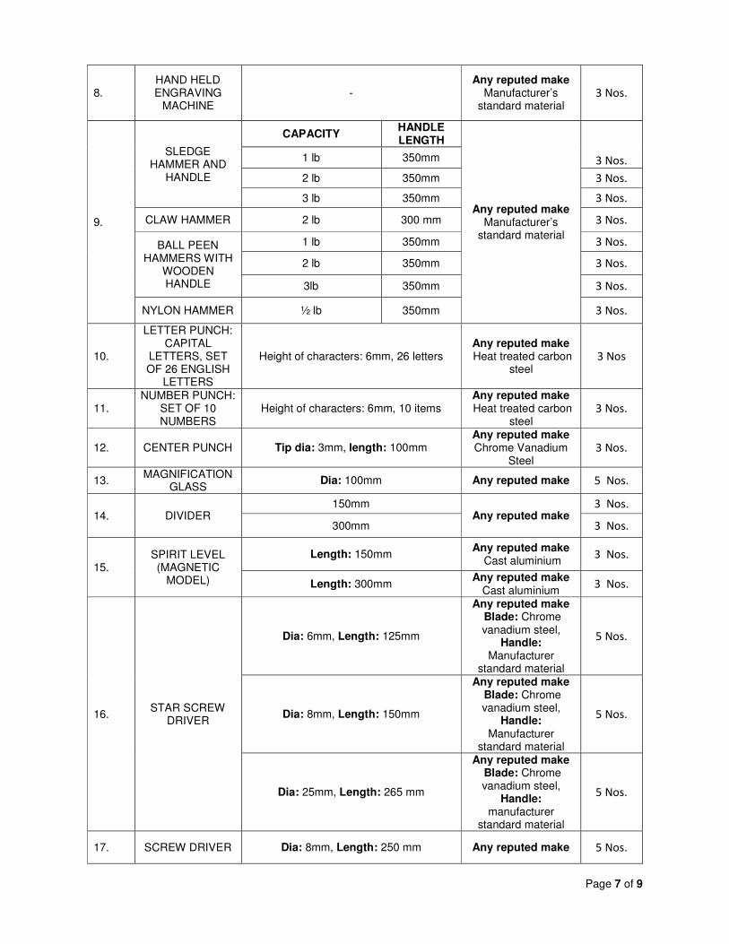
8. HAND HELD ENGRAVING
MACHINE -
Any reputed make Manufacturer’s
standard material 3 Nos.
9.
SLEDGE HAMMER AND
HANDLE
CAPACITY HANDLE LENGTH
Any reputed make Manufacturer’s
standard material
3 Nos. 1 lb 350mm
2 lb 350mm 3 Nos.
3 lb 350mm 3 Nos.
CLAW HAMMER 2 lb 300 mm 3 Nos.
BALL PEEN HAMMERS WITH
WOODEN HANDLE
1 lb 350mm 3 Nos.
2 lb 350mm 3 Nos.
3lb 350mm 3 Nos.
NYLON HAMMER ½ lb 350mm 3 Nos.
10.
LETTER PUNCH: CAPITAL
LETTERS, SET OF 26 ENGLISH
LETTERS
Height of characters: 6mm, 26 letters Any reputed make Heat treated carbon
steel 3 Nos
11. NUMBER PUNCH:
SET OF 10 NUMBERS
Height of characters: 6mm, 10 items Any reputed make Heat treated carbon
steel 3 Nos.
12. CENTER PUNCH Tip dia: 3mm, length: 100mm Any reputed make Chrome Vanadium
Steel 3 Nos.
13. MAGNIFICATION
GLASS Dia: 100mm Any reputed make 5 Nos.
14. DIVIDER 150mm
Any reputed make
3 Nos.
300mm 3 Nos.
15. SPIRIT LEVEL (MAGNETIC
MODEL)
Length: 150mm Any reputed make
Cast aluminium 3 Nos.
Length: 300mm Any reputed make
Cast aluminium 3 Nos.
16. STAR SCREW
DRIVER
Dia: 6mm, Length: 125mm
Any reputed make Blade: Chrome vanadium steel,
Handle: Manufacturer
standard material
5 Nos.
Dia: 8mm, Length: 150mm
Any reputed make Blade: Chrome vanadium steel,
Handle: Manufacturer
standard material
5 Nos.
Dia: 25mm, Length: 265 mm
Any reputed make Blade: Chrome vanadium steel,
Handle: manufacturer
standard material
5 Nos.
17. SCREW DRIVER Dia: 8mm, Length: 250 mm Any reputed make 5 Nos.
Page 8 of 9
Dia: 10mm, Length: 330 mm Blade: Chrome vanadium steel,
Handle: manufacturer
standard material
5 Nos.
Dia:11.5mm, Length: 140mm 5 Nos.
18. HAND HACKSAW
FRAME Suitable for blade length 300mm
Any reputed make Hardened steel
5 Nos.
19. HAND HACKSAW
BLADE Size: 12"X1/2"X24 TPI, Length: 300mm
Any reputed make High strength steel
200 Nos.
20.
VERNIER HEIGHT GAUGE
WITH DIAL GAUGE
Range: 0 to 600mm in increments of 0.02 mm Least count: 0.02
Make : Mitutoyo 5 Nos.
21. DIGITAL VERNIER CALIPER
Range: 0 to 300mm length, accuracy: 0.01 mm
Make : Mitutoyo 5 No.
22. DEPTH GAUGE 0.02 mm, parallax-free vernier scale,
capacity 200mm Make : Mitutoyo 5 No.
23. SCREW PITCH
GAUGE
Metric pitch ranges: 0.35mm to 6.0mm in 22 Leaves:
(0.35mm, 0.4mm, 0.45mm, 0.5mm, 0.55mm, 0.6mm, 0.7mm, 0.75mm,
0.8mm, 1mm, 1.25mm, 1.5mm, 1.75mm, 2mm, 2.5mm, 3mm, 3.5mm, 4mm,
4.5mm, 5mm, 5.5mm, 6mm & 60 Angle gauge )
Any reputed make Tool steel
3 Nos.
24.
TOOLS BOX WITH, FIVE
COMPARTMENTS, LOCK & KEY
(MEDIUM QUALITY)
500mmX400mmX300mm (LXBXH) Any reputed make
steel 6 Nos.
25. ALLEN KEYS
TOOL KIT
A / F DIMENSION (mm): 1, 1.5, 2, 2.5, 3, 4, 5, 6, 8, 10, 12, 14, 17 & 19 (1 set = 14 items each 1 no)
Any reputed make Manufacturer’s
standard material 5 sets
26. STEEL RULE 300mm Any reputed make
Stainless steel
each 5
Nos.
27. MEASURING STEEL TAPE
3m Any reputed make 5 Nos.
5m Any reputed make 5 Nos.
10m Any reputed make 3 Nos.
25m Any reputed make 3 Nos.
28. CHISEL (FLAT AND DIAMOND
POINT) Length: 100mm, section 10mm
Any reputed make Hardened steel
3 Nos.
29.
AUTOMATIC CUT-OUT MANUAL TORQUE WRENCH
SUITABLE FOR OPEN END
HEADS
RANGE: 1-36 Nm
Any reputed make Manufacturer’s
standard material
3 No.
RANGE: 5-60 Nm 3 No.
RANGE: 20-200 Nm 3 No.
RANGE: 50-1000 Nm 3 No.

Page 9 of 9
30.
OPEN ENDS, HEAD
ATTACHEMENT (TO SUIT ABOVE
TORQUE WRENCH)
METRIC SIZE: 6mm, 7mm, 8mm, 9mm, 10mm, 11mm, 12mm, 13mm, 14mm, 15mm, 16mm, 17mm, 18mm, 19mm, 20mm, 21mm, 22mm, 23mm, 24mm, 25mm, 26mm, 27mm, 29mm, 30mm,
32mm, 34mm, 36mm, 38mm (1 set= 28 items each 1 no)
Any reputed make Drop forged chrome
plated vanadium steel
3 sets

A
B
C
D
E
REF. DRG. NO.
COM. FILE NO.
F
8 7 6 5
S.NO
< 0.025
1.6 - 8
0.025 - 1.6
ASK IF IN DOUBT
ALL DIMENSIONS ARE IN MILLIMETERS
UNLESS OTHERWISE SHOWN
DO NOT SCALE THE DRAWING
8 - 25
MACHINING FINISH IN MICRONS :-
CHAMFER 1 M.M. X 45°
REMOVE SHARP EDGES & BURRS
120-400 + 0°-10 4000 & ABOVE +3.0 _SIGN. DATE
LENGTH IN M.M. OFSHORTER SIDE OF
ANGLE UPTO & INCL.
DEVIATION FOR NON TOLERANCED DIMENSIONS
30-120 + 0°-20
1- 6 + 1°-00
6- 30 + 0°-30
DIAMETERS & LENGTHS
6 - 30 +0.2
120 - 315 +0.5 315 - 1000 +0.8 1000 - 2000 +1.2 2000 - 4000 +2.0
30 - 120 +0.3
UPTO & INCL.
(IS -2102)
6 +0.1
DESIGNED
SMP&ETFSDSC
DES.CHKD
APPROVED
DRG.CHKD_
_
_DRAWN,
,
,
,
REMARKS
PROJECTION
SHEET DRG. NO.SCALE
OF
ISRO PROPULSION COMPLEXMAHENDRAGIRI
TITLE
DESCRIPTION QTYMATERIAL W.T(Kg)
A
B
C
4 3 2
D
E
1
F
STATUS
TENDER PURPOSE
FABRICATION
DISCUSSION / REVIEW
------------------------------
ONLY FOR REVIEW
------------------------------
10
3
5
4
6
7
8
9
2
13
17
15
16
18
11
19
1 12
14
ASSEMBLY SETUP DURING ENGINE TESTING
IS : 2062E250
------
EN24
------
13
2
1197
10
8
6
5
14
3
16
4
20
21
22
23
24
25
26
128
27
ASSEMBLY SETUP DURING IN-SITU CALIBRATION
TEST STAND FORSEMI CRYO INTEGRATED ENGINE TEST FACILITY
(3-D VIEWS OF SUB-SYSTEMS)
1 : 12 IPRC-SIET-TMS-01/A1 21
TOTAL WEIGHT : 80,750 Kgs. (Approx)
REVISIONS SIGNZONE DATE
1 SPACER FRAME 1
2
3
4
5
6
7
8
9
10
11
12
13
14
15
16
17
18
1550
PRE LOAD SUSPENSION ASSEMBLY
PRE LOAD FRAME
CALIBRATION INTERFACE PLATE
PLATE FOR PRE LOAD SUSPENSION
ALIGNMENT JACKS
SIDE FORCE CALIBRATION LINKASSEMBLY
LATERAL SAFETY STOPPER
ATTACHMENT BLOCK TWIN EYE
ATTACHMENT BLOCK
ROLL LINK ASSEMBLY
PITCH FORCE/YAW FORCE LINK
SIDE FRAME-2
SIDE FRAME-1
ATMS INTERFACE PLATE
AXIAL LINK ASSEMBLY
THRUST FRAME
FIXED FRAME
4
1
1
1
8
1
3
1
1
1
2
1
2
1
3
1
1
16800
7620
2800
895
40
305
162
36
10
18
20
150
360
3495
886
7050
8315
CONDITION-T
IS : 2062
IS : 2062
IS : 2062
IS : 2062
IS : 2062
EN 24
20
19
CALIBRATION FRAME
PULLEY BRACKET ASSEMBLY
IS : 2062
IS : 2062
1
4
7175
740
CONDITION-T
CONDITION-T
EN 24
EN 24
EN 24
EN 24
IS 2062:E250,IS 2004:20C8,ASTM A106 GR.B
IS 2062:E250,IS 2004:20C8,ASTM A106 GR.B
IS : 2062E250
E250IS : 2062
IS : 2062E450
IS : 2062E450
E250
E450IS : 2062
EN 24
E250
E250
E250
E250
E250
E250
29
28
27
26
25
24
23
22
21
LOADING FRAME
CALIBRATION PLATE
WORKING PLATFORM
IN-SITU TIE ROD
300T LOAD CELL
IN-SITU CALIBRATION LINK
SPHERICAL BEARING & BEARING HOUSING
HYDRAULIC JACK ADAPTOR
1000T HYDRAULIC JACK
IS : 2062
IS : 2062
IS : 2062
IS : 2062
EN24
E250
E250/EN24
E250
E250
1
1
1
1
1
1
1
1
1
---
2865
830
1280
---
290
110
510
---
32
31
30
ALL HANDLING SYSTEMS
ALL BOUGHTOUT ITEMS
ALL NUTS,BOLTS & WASHERS
------
------
------
LOT
LOT
LOT
---
---
---
REFER ANNEXURE-2
REFER ANNEXURE-3
33 COMPONENTS FOR LOAD TESTING -- 15550
IPRC-SIET-TMS-03
REFER ANNEXURE-1
NOT SHOWN IN THE DRAWING
IPRC-SIET-TMS-09
IPRC-SIET-TMS-09
IPRC-SIET-TMS-09
IPRC-SIET-TMS-09
IPRC-SIET-TMS-09
IPRC-SIET-TMS-09
IPRC-SIET-TMS-09
IPRC-SIET-TMS-09
IPRC-SIET-TMS-09
IPRC-SIET-TMS-08
IPRC-SIET-TMS-08
IPRC-SIET-TMS-08
IPRC-SIET-TMS-06
IPRC-SIET-TMS-05
IPRC-SIET-TMS-05
IPRC-SIET-TMS-07
IPRC-SIET-TMS-05
IPRC-SIET-TMS-07
IPRC-SIET-TMS-07
IPRC-SIET-TMS-07
IPRC-SIET-TMS-07
IPRC-SIET-TMS-07
IPRC-SIET-TMS-07
IPRC-SIET-TMS-06
IPRC-SIET-TMS-02
IPRC-SIET-TMS-05
IPRC-SIET-TMS-04
IPRC-SIET-TMS-10
EN24
GENERAL NOTE:
THE SEQUENCE OF FABRICATION/ERECTION OF THE1.INDIVIDUAL COMPONENTS IS LISTED IN THE RESPECTIVEDRAWINGS.THE PART LIST GIVES THE SUMMARY OF ALL THE2.COMPONENTS REQUIRED TO COMPLETE THE ASSEMBLY.AS SEVERAL ITEMS ARE BOUGHT-OUT, THE ACTUALQUATITIES (INCLUDING SPARES) IS LISTED IN ANNEXURE-2. THE SUPPLY OF THE ITEMS SHALL BE AS PER THE LISTGIVEN IN ANNEXURE-2ALL THE FASTENERS, BOLTS & WASHERS ARE LISTED IN3.ANNEXURE-1. LENGTH OF THE FASTENERS TO BEENSURED AT FABRICATOR SITE DURING TRIAL ASSEMBLYBEFORE SUPPLY.ALL HANDLING& AUXILARY SYSTEMS ARE PROVIDED IN4.ANNEXURE-3.ANY CHANGE IN THE MATERIAL/DIMENSIONS IN ANY OF5.THE COMPONENTS HAS TO BE MADE ONLY AFTER PRIORAPPROVAL FROM THE DESIGNER AS PER REVISEDDRAWING PROVIDED.
NOTE:DRAWINGS TO BE READ IN CONJUCTION WITH1.A) MEC/11/12/10HV/LDF/D/30001-30003 -REV2 (SHEETS- 3 NOS.) FOR INTEGRATED ENGINE TEST
FACILITY LOADING FRAME (ENGINE BAY)B) SE 2000.0500.2000.00.0AD FOR FRAME ASSSEMBLYTHE OUTER DIMENSIONS OF LOADING FRAME IS USED IN THE DRAWINGS FOR REPRESENTATION2.PURPOSE. NOT TO BE CONSIDERED FOR ANY FABRICATION DETAILS. REFERMEC/11/12/10HV/LDF/D/30001-30003 -REV2.ALL CRITICAL WELDS ARE TO BE QUALIFIED WITH DP TESTING / ULTRASONIC TESTING/ RADIOGRAPHY3.ALL SHARP CORNERS ARE TO BE CHAFERED SUITABLY4.ALL WELDS ARE 6 mm UNLESS OTHERWISE SPECIFIED5.STRESS RELIEVING IS TO BE DONE FOR ALL THE PARTS WHEREVER HEAVY MACHNING / WELDING IS6.INVOLVEDCHECK FOR THE STATUS OF DRAWING BEFORE FABRICATION / MACHINING7.
TOTAL NO. OF DRAWING SHEETS : 11

A
B
C
D
E
REF. DRG. NO.
COM. FILE NO.
F
8 7 6 5
S.NO
< 0.025
1.6 - 8
0.025 - 1.6
ASK IF IN DOUBT
ALL DIMENSIONS ARE IN MILLIMETERS
UNLESS OTHERWISE SHOWN
DO NOT SCALE THE DRAWING
8 - 25
MACHINING FINISH IN MICRONS :-
CHAMFER 1 M.M. X 45°
REMOVE SHARP EDGES & BURRS
120-400 + 0°-10 4000 & ABOVE +3.0 _SIGN. DATE
LENGTH IN M.M. OFSHORTER SIDE OF
ANGLE UPTO & INCL.
DEVIATION FOR NON TOLERANCED DIMENSIONS
30-120 + 0°-20
1- 6 + 1°-00
6- 30 + 0°-30
DIAMETERS & LENGTHS
6 - 30 +0.2
120 - 315 +0.5 315 - 1000 +0.8 1000 - 2000 +1.2 2000 - 4000 +2.0
30 - 120 +0.3
UPTO & INCL.
(IS -2102)
6 +0.1
DESIGNED
SMP&ETFSDSC
DES.CHKD
APPROVED
DRG.CHKD_
_
_DRAWN,
,
,
,
REMARKS
PROJECTION
SHEETDRG. NO.SCALE
OF
ISRO PROPULSION COMPLEXMAHENDRAGIRI
TITLE
DESCRIPTION QTYMATERIAL W.T(Kg)
A
B
C
4 3 2
D
E
1
F
STATUS
TENDER PURPOSE
FABRICATION
DISCUSSION / REVIEW
------------------------------
ONLY FOR REVIEW
------------------------------
3
2
4 12
11
9
7
68
10
6
8
1
13
(VIEW FROM BOTTOM OF LOADING FRAME)
A
A
19
17
16
20
(VIEW FROM TOP OF LOADING FRAME)
SECTION A-ASCALE 1 : 15
1 3
4
6
8 10
14
15
16
17
18
19
2
5
20
1 A
1 B
AB
15TYP
15TYP
15TYP15TYP
TEST STAND FORSEMI CRYO INTEGRATED ENGINE TEST FACILITY
(OVERALL ASSEMBLY DETAILS)
1 : 20 IPRC-SIET-TMS-01/A1 22
TOTAL WEIGHT : 51250 Kgs. (Approx)
REVISIONS SIGNZONE DATE
IPRC-SIET-TMS-04
IPRC-SIET-TMS-05
IPRC-SIET-TMS-02
IPRC-SIET-TMS-06
IPRC-SIET-TMS-07
IPRC-SIET-TMS-07
IPRC-SIET-TMS-07
IPRC-SIET-TMS-07
IPRC-SIET-TMS-07
IPRC-SIET-TMS-07
IPRC-SIET-TMS-05
IPRC-SIET-TMS-07
IPRC-SIET-TMS-05
IPRC-SIET-TMS-05
IPRC-SIET-TMS-06
IPRC-SIET-TMS-08
IPRC-SIET-TMS-08
IPRC-SIET-TMS-08E250
E250
E250
E250
E250
EN 24
IS : 2062E450
E250
E450IS : 2062
E450IS : 2062
IS : 2062E250
IS 2062:E250,IS 2004:20C8,ASTM A106 GR.BIS 2062:E250,IS 2004:20C8,ASTM A106 GR.B
EN 24
EN 24
EN 24
EN 24
CONDITION-T
CONDITION-T
7404IS : 2062PULLEY BRACKET ASSEMBLY19
EN 24
IS : 2062
IS : 2062
IS : 2062
IS : 2062
IS : 2062
CONDITION-T
8315
7050
886
3495
360
150
20
18
10
36
162
305
40
895
2800
7620
16800
1
1
3
1
2
1
2
1
1
1
3
1
8
1
1
1
4
FIXED FRAME
THRUST FRAME
AXIAL LINK ASSEMBLY
ATMS INTERFACE PLATE
SIDE FRAME-1
SIDE FRAME-2
PITCH FORCE/YAW FORCE LINK
ROLL LINK ASSEMBLY
ATTACHMENT BLOCK
ATTACHMENT BLOCK TWIN EYE
LATERAL SAFETY STOPPER
SIDE FORCE CALIBRATION LINKASSEMBLY
ALIGNMENT JACKS
PLATE FOR PRE LOAD SUSPENSION
CALIBRATION INTERFACE PLATE
PRE LOAD FRAME
PRE LOAD SUSPENSION ASSEMBLY 18
17
16
15
14
13
12
11
10
9
8
7
6
5
4
3
2
IPRC-SIET-TMS-0315501IS : 2062E250
SPACER FRAME1
SHOWN ONLY FOR REPRESENTATION---1E250
IS : 2062LOADING FRAME20 NOTE:DRAWINGS TO BE READ IN CONJUCTION WITH1.A) MEC/11/12/10HV/LDF/D/30001-30003 -REV2 (SHEETS- 3 NOS.) FOR INTEGRATED ENGINE TESTSFACILITY LOADING FRAME (ENGINE BAY) B) SE 2000.0500.2000.00.0AD FOR FRAME ASSSEMBLYTHE OUTER DIMENSIONS OF LOADING FRAME IS USED IN THE DRAWINGS FOR REPRESENTATION2.PURPOSE. NOT TO BE CONSIDERED FOR ANY FABRICATION DETAILS. REFERMEC/11/12/10HV/LDF/D/30001-30003 -REV2.ALL CRITICAL WELDS ARE TO BE QUALIFIED WITH DP TESTING / ULTRASONIC TESTING/ RADIOGRAPHY3.ALL SHARP CORNERS ARE TO BE CHAFERED SUITABLY4.ALL WELDS ARE 6 mm UNLESS OTHERWISE SPECIFIED5.STRESS RELIEVING IS TO BE DONE FOR ALL THE PARTS WHEREVER HEAVY MACHNING / WELDING IS6.INVOLVEDCHECK FOR THE STATUS OF DRAWING BEFORE FABRICATION / MACHINING.7.
SEQUENCE OF ERECTION:THE AXIAL THRUST MEASUREMENT SYSTEM IS CONNECTED TO1.BOTTOM OF LOADING FRAME THROUGH PART-5. THEWELDING OF THE ABOVE 60 Thk PLATE IS TO BE DONE WITHA WELD SIZE OF 15 MM ON BOTH OUTER AND INNERDIAMETERS(4750 AND 3400 MM RESPECTIVELY) AS SHOWN,AFTER OBTAINING CLEARANCE FROM SIET/IPRC.THE CALIBRATION SYSTEM IS CONNECTED TO TOP OF2.LOADING FRAME THROUGH PART-16.THE WELDING OF THEABOVE 60 Thk PLATE IS TO BE DONE WITH A WELD SIZE OF 15MM ON BOTH OUTER AND INNER DIAMETERS(4750 AND 3500MM RESPECTIVELY) AS SHOWN, AFTER OBTAININGCLEARANCE FROM SIET/IPRC.PRIOR TO THE WELDING OF THE PART-5 & PART-16, THE3.FOLLOWING IS TO BE ENSURED:
PLANARITY OF THE TOP & BOTTOM FACES WITH IN 1 MM.•CONCENTRICITY OF BOTH THE PLATES W.R.T LOADING•FRAME WITH IN 1MM.MATCHING OF AXES II-IV & I-III OF PART-5 & 16 WITH 2-4•&1-3 AXES OF LOADING FRAME.
REFERENCE AXIS:X- DIRECTION – ENGINE THRUST AXIS1.Y- DIRECTION – ENGINE II- IV AXIS2.Z- DIRECTION – ENGINE I-III AXIS3.
(THE AXIS MARKING OF I-II-III-IV ARE GIVEN IN PART DRAWINGS OF INDIVIDUAL COMPONENTS. WHEREVER MENTIONED, THESE ARE TO PUNCHED ON THE COMPONENTS DURING FABRICATION)
A
B
C
D
E
REF. DRG. NO.
COM. FILE NO.
F
8 7 6 5
S.NO
< 0.025
1.6 - 8
0.025 - 1.6
ASK IF IN DOUBT
ALL DIMENSIONS ARE IN MILLIMETERS
UNLESS OTHERWISE SHOWN
DO NOT SCALE THE DRAWING
8 - 25
MACHINING FINISH IN MICRONS :-
CHAMFER 1 M.M. X 45°
REMOVE SHARP EDGES & BURRS
120-400 + 0°-10 4000 & ABOVE +3.0 _SIGN. DATE
LENGTH IN M.M. OFSHORTER SIDE OF
ANGLE UPTO & INCL.
DEVIATION FOR NON TOLERANCED DIMENSIONS
30-120 + 0°-20
1- 6 + 1°-00
6- 30 + 0°-30
DIAMETERS & LENGTHS
6 - 30 +0.2
120 - 315 +0.5 315 - 1000 +0.8 1000 - 2000 +1.2 2000 - 4000 +2.0
30 - 120 +0.3
UPTO & INCL.
(IS -2102)
6 +0.1
DESIGNED
SMP&ETFSDSC
DES.CHKD
APPROVED
DRG.CHKD_
_
_DRAWN,
,
,
,
REMARKS
PROJECTION
SHEETDRG. NO.SCALE
OF
ISRO PRPULSION COMPLEXMAHENDRAGIRI
TITLE
DESCRIPTION QTYMATERIAL W.T(Kg)
A
B
C
4 3 2
D
E
1
F
1
34
5
6
7
8
9
10
1112
13
14
2
AXIAL THRUST MEASURMENT SYSTEM
115
0
605
544
.75
194
2
3250
4750
4500
3100
1700
105
5
R2375 R2250 R
1550
R850
R1200
R625
R900
30°
30°
45°
45°
XX
II
IIII
IV
350
12.
25
1700
1250
3100
2750 PCD
SECTION X-XSCALE 1 : 15
AA
AA
4A
4B
4A
4C
4C
4D
4D
350
225
115
162
194
2
186
2
SECTION AA-AASCALE 1 : 10
225
g6
163.
30
115 R27
.50
R40
135 51.5
BBBB
M90
X4
90
135
5
45°
145
115 R40
850
225
g6
51.5
7°
R27
.50
163.
30
SECTION BB-BBSCALE 1 : 5
5 MM UNDER CUT
PART - 4A
AXIAL LINK ASSEMBLY(QUANTITY - 3 NOS.)
95
111 340
M90 x 4 - 85 Lg
PART-4B(SCALE 1:5)
LOAD CELL SPECIFICATIONS:MAKE : SENSY/ EQUIVALENT
MODEL : 5105CAPACITY :1 MN
(NOTE: 3 NOS. OF DUMMY LOAD CELLS ARE TO BE SUPPLIED AS PER THE DIMENSIONS MENTIONED ABOVE.
MATERIAL : EN-24 CONDITION-T)DDDD
32 HOLES ON 290 PCD - 4 Nos.
30° T
YP
30°
CC
CC
M 30 TAPPED HOLES ON 290 PCD, THROUGH - 4 Nos.
26 HOLES ON 290 PCD WITH 40 COUNTERBORE
24 DEEP - 8 Nos.
350 --0.200.50
290 PCD
170
60
40 24
M24
225 H7
25.
4
7°
SECTION CC-CCSCALE 1 : 5PART - 4C
350
225 H7 290 PCD
20 60
32
SECTION DD-DDSCALE 1 : 5PART - 4D
1 SPACER FRAME 1
2
3
4
AXIAL THRUST MEASURMENT SYTEM &
AXIAL LINK ASSEMBLY DETAILS
1 : 15 IPRC-SIET-TMS-02/A1 11
1550
REVISIONS SIGNZONE DATE
AXIAL LINK ASSEMBLY
THRUST FRAME
FIXED FRAME
3
1
1
886
7050
8315
CONDITION-TEN 24
IS 2062:E250,IS 2004:20C8,ASTM A106 GR.B
IS 2062:E250,IS 2004:20C8,ASTM A106 GR.B
IS : 2062E250
DISCUSSION / REVIEW
FABRICATION
TENDER PURPOSE
STATUS
4D
4C
4B
4A
FLEXURE COVER PLATE
FLEXURE SEATING PLATE
LOAD CELL
MEASUREMENT FLEXURE
CONDITION-T
CONDITION-T
CONDITION-T
6
6
3
6
222
162
-
502
EN 24
EN 24
MAKE: SENSY/ EQUIVALENT
EN 24
DUMMY LOAD CELL TO BE SUPPLIED
E250IS : 2062E450
E250
E450IS : 2062
E450IS : 2062
IS : 2062
EN 24
EN 24
EN 24
EN 24
CONDITION-T
CONDITION-T
IS : 2062
IS : 2062
3495
360
150
20
18
10
36
162
305
40
1
2
1
2
1
1
1
3
1
8
ATMS INTERFACE PLATE
SIDE FRAME-1
SIDE FRAME-2
PITCH FORCE/YAW FORCE LINK
ROLL LINK
ATTACHMENT BLOCK
ATTACHMENT BLOCK TWIN EYE
LATERAL SAFETY STOPPER
SIDE FORCE CALIBRATION LINKASSEMBLY
ALIGNMENT JACKS14
13
12
11
10
9
8
7
6
5 E250
NOTE:ALL CRITICAL WELDS ARE TO BE QUALIFIED WITH DP1.
TESTING / ULTRASONIC TESTING / RADIOGRAPHY2. ALL SHARP CORNERS ARE TO BE CHAFERED SUITABLY3. ALL WELDS ARE 6 mm UNLESS OTHERWISE SPECIFIED4. STRESS RELIEVING IS TO BE DONE FOR ALL THE PARTS WHEREVER HEAVY MACHNING /WELDING IS INVOLVED5. CHECK FOR THE STATUS OF DRAWING BEFORE FABRICATION / MACHNING
ONLY FOR REVIEW

A
B
C
D
E
REF. DRG. NO.
COM. FILE NO.
F
8 7 6 5
S.NO
< 0.025
1.6 - 8
0.025 - 1.6
ASK IF IN DOUBT
ALL DIMENSIONS ARE IN MILLIMETERS
UNLESS OTHERWISE SHOWN
DO NOT SCALE THE DRAWING
8 - 25
MACHINING FINISH IN MICRONS :-
CHAMFER 1 M.M. X 45°
REMOVE SHARP EDGES & BURRS
120-400 + 0°-10 4000 & ABOVE +3.0 _SIGN. DATE
LENGTH IN M.M. OFSHORTER SIDE OF
ANGLE UPTO & INCL.
DEVIATION FOR NON TOLERANCED DIMENSIONS
30-120 + 0°-20
1- 6 + 1°-00
6- 30 + 0°-30
DIAMETERS & LENGTHS
6 - 30 +0.2
120 - 315 +0.5 315 - 1000 +0.8 1000 - 2000 +1.2 2000 - 4000 +2.0
30 - 120 +0.3
UPTO & INCL.
(IS -2102)
6 +0.1
DESIGNED
SMP&ETFSDSC
DES.CHKD
APPROVED
DRG.CHKD_
_
_DRAWN,
,
,
,
REMARKS
PROJECTION
SHEETDRG. NO.SCALE
OF
ISRO PROPULSION COMPLEXMAHENDRAGIRI
TITLE
DESCRIPTION QTYMATERIAL W.T(Kg)
A
B
C
4 3 2
D
E
1
F
3.7
5°
7.5° (TYP)
7.5° (TYP)
X
X
10 THK STIFFENERS (PART-4)- 48 NOS.
10 THK STIFFENERS (PART-3)- 48 NOS.
370
45
45 1800
1700
1420 +0.25
0
7
18
SECTION X-XSCALE 1 : 6
0.2 A
0.2 A
B
A
15 TYP
70 210
70
70
56 112
56 28
57°
57°
1250
1700
R780
R795
PART-2
M20 TAPPED HOLES, 40 DEEP. ON 1560 PCD- 20 NOS.(TO SUIT ENGINE FRAME ASSEMBLY)
UNDER HOLD
M12 TAPPED HOLES, 20 DEEP. ON 1590 PCD- 14 NOS.(TO SUIT ENGINE FRAME ASSEMBLY)
1250 1800
3.7
5°
18 THROUGH HOLES EQUISPACED ON 1710 PCD- 48 NOS.
50
1620
DEVELOPMENT OF PART-5(PLATE SIZE REQUIRED 280x50Thk - 5010Lg)
20 TYP
90
280
40
135
280
1
2
3
3
5
1 1
2
3
4
5
SPACER FRAME
1 : 6 IPRC-SIET-TMS-03/A1 11
440
TOTAL WEIGHT : 1550 Kgs. (Approx)
REVISIONS SIGNZONE DATE
CIRCULAR RING-O.D1620XWIDTH280X50Thk
STIFFENER-280X135X10Thk
STIFFENER-280X90X10Thk
1
45
45
1
540
140
65
365
IS : 2062E250
DISCUSSION / REVIEW
FABRICATION
TENDER PURPOSE
STATUS
PART-3(THE EXISTING GAP BETWEEN
BOTH ENDS HAS TO BE CHECKED BEFOREWELDINGTHE RIB)
PART-4(THE EXISTING GAP BETWEEN
BOTH ENDS HAS TO BE CHECKED BEFORE WELDING THE RIB)
IVII
I
III
PART-1
BIG END PLATE-O.D1800XI.D1250X45Thk
SMALL END PLATE-O.D1700XI.D1250X45Thk
IS : 2062E250
IS : 2062E250
IS : 2062E250
IS : 2062E250
NOTE:ALL CRITICAL WELDS ARE TO BE QUALIFIED WITH DP1.
TESTING / ULTRASONIC TESTING / RADIOGRAPHY2. ALL SHARP CORNERS ARE TO BE CHAFERED SUITABLY3. ALL WELDS ARE 6 mm UNLESS OTHERWISE SPECIFIED4. STRESS RELIEVING IS TO BE DONE FOR ALL THE PARTS WHEREVER HEAVY MACHNING /WELDING IS INVOLVED5. CHECK FOR THE STATUS OF DRAWING BEFORE FABRICATION / MACHNING
ENGINE INTERFACE ON HOLD. CLEARNACE TO BE OBTAINED FROM SIET/IPRC
UNDER HOLD
SEQUENCE OF FABRICATION:PRE-MACHINING OF PART-1 AND PART-21.WELDING OF PART 3, PART-4 AND PART-5 AND FOLLOWED BY STRESS RELIEVING2.FINAL MACHINING OF END FLANGES FOR PLANARITY3.DRILLING & TAPPING OF INTERFACE HOLESIN SINGLE SEETING AS PER GIVEN TOLERANGES4.
ONLY FOR REVIEW
A
B
C
D
E
REF. DRG. NO.
COM. FILE NO.
F
8 7 6 5
S.NO
< 0.025
1.6 - 8
0.025 - 1.6
ASK IF IN DOUBT
ALL DIMENSIONS ARE IN MILLIMETERS
UNLESS OTHERWISE SHOWN
DO NOT SCALE THE DRAWING
8 - 25
MACHINING FINISH IN MICRONS :-
CHAMFER 1 M.M. X 45°
REMOVE SHARP EDGES & BURRS
120-400 + 0°-10 4000 & ABOVE +3.0 _SIGN. DATE
LENGTH IN M.M. OFSHORTER SIDE OF
ANGLE UPTO & INCL.
DEVIATION FOR NON TOLERANCED DIMENSIONS
30-120 + 0°-20
1- 6 + 1°-00
6- 30 + 0°-30
DIAMETERS & LENGTHS
6 - 30 +0.2
120 - 315 +0.5 315 - 1000 +0.8 1000 - 2000 +1.2 2000 - 4000 +2.0
30 - 120 +0.3
UPTO & INCL.
(IS -2102)
6 +0.1
DESIGNED
SMP&ETFSDSC
DES.CHKD
APPROVED
DRG.CHKD_
_
_DRAWN,
,
,
,
REMARKS
PROJECTION
SHEETDRG. NO.SCALE
OF
ISRO PROPULSION COMPLEXMAHENDRAGIRI
TITLE
DESCRIPTION QTYMATERIAL W.T(Kg)
A
B
C
4 3 2
D
E
1
F
X
X
Y Y
IV
I
II
III
-
15TYP
12 TYP
1
2
7
3
5
6
4
8
55°
R 1475
R 1200
R 1981.5
R 1375
R 2250
R 1550
SECTION X-XWELD DETAILS
PART-5(SCALE 1:10)
PART-7(SCALE 1:5)
15 TYP
15 TYP
6 TYP
12 TYP
62.
75
110
00.
2
4500 --0.500.75
SECTION Y-YSCALE 1 : 15
0.2 A0.2 A
A
20°
15° 1
0°
15°
20°
20°
15°
15° 10°
30°
10° 15°
15° 20
°
20°
10°
10°
15°
30°
15°
20°
2950
4500
10°
15°
15°
40 THROUGH HOLES ON 3700 PCD,19 NOS.
40 THROUGH HOLES ON 4300 PCD,19 NOS.
40 THROUGH HOLES ON 4000 PCD,16 NOS.
PART-1(DETAILS OF CONSTRUCTION AND THROUGHHOLES)
I
II
III
IV
TYP
1875 0.5
130
125
260
500 105
50.
5 1550 0.5
115
105
420
230
15°
45°TYP
45° 45°
PART-1(DETAILS OF TAPPED HOLES FOR SIDE FRAMES
AND ALIGNMENT JACKS)
II
I
IV
III
M90X4 TAPPED HOLES, THROUGH, EQUISPACED ON 3140 PCD, 8 NOS.
M36X4 TAPPED HOLES, THROUGH, 12 NOS. ( AT 6 LOCATIONS AS SHOWN)
M36X4 TAPPED HOLES, THROUGH, 11 NOS.(AT 2 LOCATIONS AS SHOWN)
6°TYP 6°TYP
120°
120°
120°
30°
30° Z
ZM20 TAPPED HOLES, 30 DEEP,
ON 2450 PCD, 9 NOS. (ON BOTH SIDES)
150 THROUGH HOLES EQUISPACED ON 2750 PCD,3 NOS.
PART-2PART-8
(SCALE 1:5)
3100
2400
180
82.50
100
100
125°
SECTION Z-Z
520
1055
84.25
° 310
R80
160
96.
5
80
PART-4(THE EXISTING GAP BETWEEN THE
PIPES HAS TO BE CHECKED BEFOREWELDINGTHE PLATE)
140
55°
1115
300
700
100
150
50
350
R120
0
R155
0 150
30°
30°
M24 TAPPED HOLES, 48 DEEP, ON 290 PCD, 8 NOS.
(TO BE DRILLED AFTER WELDING) 85
205
115
25
100 200
80 25
1 BIG END PLATE 1
2
3
4
5
6
7
8
FIXED FRAME
1 : 15 IPRC-SIET-TMS-04/A1 11
4350
TOTAL WEIGHT : 8350 Kgs. (Approx)
REVISIONS SIGNZONE DATE
STIFFENER-200x100x16Thk
STIFFENER-205x85x16Thk
STIFFENER-1115x140x16Thk
BASE PLATE- 40 Thk
STIFFENER-1055x520x20Thk
PIPE-O.D 168.28x21.95Thk1115Lg (Approx.)
SMALL END RING
6
6
6
3
3
6
1
12
12
64
217
195
530
2970IS : 200420C8
ASTM A106GR.B
IS : 2062E250
DISCUSSION / REVIEW
FABRICATION
TENDER PURPOSE
STATUS
PART-6(THE EXISTING GAP BETWEEN
BOTH ENDS HAS TO BE CHECKED BEFOREWELDINGTHE RIB)
XXS SCHEDULE
IS : 2062E250
IS : 2062E250
IS : 2062E250
IS : 2062E250
IS : 2062E250
NOTE:ALL CRITICAL WELDS ARE TO BE QUALIFIED WITH DP1.
TESTING / ULTRASONIC TESTING / RADIOGRAPHY.2. ALL SHARP CORNERS ARE TO BE CHAFERED SUITABLY.3. ALL WELDS ARE 6 mm UNLESS OTHERWISE SPECIFIED4. STRESS RELIEVING IS TO BE DONE FOR ALL THE PARTS WHEREVER HEAVY MACHNING /WELDING IS INVOLVED.5. CHECK FOR THE STATUS OF DRAWING BEFORE FABRICATION / MACHNING.
SEQUENCE OF FABRICATION:PREPARATION OF PART-1 BY WELDING FROM TWO PLATE1.SEGMENTS AS PER DRAWING. APPROVAL IS TO BEOBATIANED FROM DESIGNER IN CASE OF NON-AVAILABITYOF REQUIRED PLATE SIZES ALONG WITH PROPOSEDSEGMENT SIZES.PRE-MACHINING OF PART-1 AND PART-2.2.WELDING OF PART 3, PART-4 AND PART-5 AFTER3.ENSURING GAPS BETWEEN PIPES, FOLLOWED BY STRESSRELIEVING.FINAL MACHINING OF PART-1 AND PART-5 END FACES FOR4.PLANARITY.DRILLING & TAPPING OF ALL INTERFACE HOLES ON END5.FACES AS PER TOLERANCE SPECIFICATIONS IN A SINGLESETTING.
ONLY FOR REVIEW
A
B
C
D
E
REF. DRG. NO.
COM. FILE NO.
F
8 7 6 5
S.NO
< 0.025
1.6 - 8
0.025 - 1.6
ASK IF IN DOUBT
ALL DIMENSIONS ARE IN MILLIMETERS
UNLESS OTHERWISE SHOWN
DO NOT SCALE THE DRAWING
8 - 25
MACHINING FINISH IN MICRONS :-
CHAMFER 1 M.M. X 45°
REMOVE SHARP EDGES & BURRS
120-400 + 0°-10 4000 & ABOVE +3.0 _SIGN. DATE
LENGTH IN M.M. OFSHORTER SIDE OF
ANGLE UPTO & INCL.
DEVIATION FOR NON TOLERANCED DIMENSIONS
30-120 + 0°-20
1- 6 + 1°-00
6- 30 + 0°-30
DIAMETERS & LENGTHS
6 - 30 +0.2
120 - 315 +0.5 315 - 1000 +0.8 1000 - 2000 +1.2 2000 - 4000 +2.0
30 - 120 +0.3
UPTO & INCL.
(IS -2102)
6 +0.1
DESIGNED
SMP&ETFSDSC
DES.CHKD
APPROVED
DRG.CHKD_
_
_DRAWN,
,
,
,
REMARKS
PROJECTION
SHEETDRG. NO.SCALE
OF
ISRO PROPULSION COMPLEXMAHENDRAGIRI
TITLE
DESCRIPTION QTYMATERIAL W.T(Kg)
A
B
C
4 3 2
D
E
1
F
1
5
3
4A
2
4B
120
° TYP
15°
30° 30°
30°
30°
30° 30°
45° TYP
30°
30°
X
X
150 THROUGH HOLE ON 2750 PCD EQUISPACED ,3 NOS. 68 HOLE, 5 mm DEEP
ON 3140 PCD EQUISPACED ,8 NOS.
M 48 TAPPED THROUGH HOLE, ON 2400 PCD , 9 NOS.
III
IV
I
II0.1 B
0.1 B
0.1 B
3250 2250
3140 PCD
M48
150 68
5
150
175
150
175
65
150°
SECTION X-XSCALE 1 : 15PART-1
45° TYP
7.5°
15° TYP 3.75°
7.5° TYP
120
YY
III
IV
I
M 16 TAPPED HOLE, 30 DEEP ON 1710 PCD , EQUISPACED ,48 NOS.
M 56 TAPPED HOLE, 60 DEEP RADIALLY , EQUISPACED ,8 NOS.
M 20 TAPPED HOLE, 40 DEEP ON 1330 PCD ,EQUISPACED ,24 NOS.
0.1 B
0.1 B
0.1 B
1420
1800
1260
5
185
95
30°
46.35 M 20
M 16
SECTION Y-YSCALE 1 : 10
95 120
45
180
5
R16
25
R112
5
20°
30°
30°
R1375
30°
ZZ
M 24 TAPPED HOLE, 48 DEEP ON 290 PCD,8 NOS.
(TO BE DRILLED AFTER WELDING)
150
5
37 350
++
0.500.20
SECTION Z-ZSCALE 1 : 10
1190
1190 237.5
554.5
SCALE 1:10PART-4A
(THE EXISTING GAP BETWEEN THEPIPES HAS TO BE CHECKED BEFOREWELDINGTHE PLATE)
15°
30° TYP
30°
30°
N
N
P
P
II
III
IV
I
68 HOLE, 5 mm DEEP ON 3140 PCD EQUISPACED ,8 NOS.
M 24 TAPPED HOLE, 48 DEEP ON 190 PCD,8 NOS.
10 TYP
15 TYP
127
5.50
1260
1420
1800
95
185
150
37
5
60°
3250
2250
68
5
1560 PCD
2750 PCD
119
0
SECTION N-NSCALE 1 : 15
0.2 A
A
15 TYP
15 TYP
M 5
6 X
5.5
50
+ -0.10
0.10
2750 PCD
185
95
1420 --0.150.30
5
CSECTION P-PSCALE 1 : 15
0.2 A0.2 B
0.2 B
BA
15 TYP
350 +0.25
0
5
68
5
150
3
7
65
DETAIL CSCALE 1 : 5
0.2 B0.2 A 15 TYP
1410
15° TYP
7.5°
38 THROUGH HOLE ON 1330 PCD EQUISPACED ,24NOS.
36 THROUGH HOLE ON 1100 PCD EQUISPACED , 4 NOS.
1410 4
0 1100 PCD
SECTION Q-QSCALE 1 : 10
PART-6
250
300
1900
2400
2500
15°
6°
6° T
T
22 THROUGH HOLE ON 2450 PCD , 3NOS.
12 TYP
16
16
180
24 24
212
22
22SECTION T-TSCALE 1 : 5PART-7
12 TYP
30
Tilt Saddle
Mechanical Jack
Mechanical JackSeating Block
M 90 X4 Thin Lock NutWITH A/F 140, 30 THK
R
R
140
657
50 155
30
62.75
SECTION R-RSCALE 1 : 5
PART-8
M 6
4 SQ
THR
EAD
500
525
595
32.5
36 T
HRO
UGH
HOLE
S
45°
5
140
39.3
50
MECHANICAL JACK
160
45°
5
M 90 X4
100
155
M 64 SQ THREAD
MECHANICAL JACKSEATING BLOCK
1190
237.50
1190
42.5
R50
168.5 554.5
142.5
SCALE 1:10
PART-4B(THE EXISTING GAP BETWEEN THE
PIPES HAS TO BE CHECKED BEFOREWELDINGTHE PLATE)
1 BIG END RING 1
2
3
4A
5
THRUST FRAME
1 : 15 IPRC-SIET-TMS-05/A1 11
TOTAL WEIGHT : 8050 kg. (Approx)
REVISIONS SIGNZONE DATE
STIFFENER-1
PIPE O.D168.28X21.95Thk-1190Lg
SMALL END RING
3
3
12
1
IS : 200420C8
DISCUSSION / REVIEW
FABRICATION
TENDER PURPOSE
STATUS
II
E250
E250
20C8
IS : 2062
IS : 2062
ASTM A 106Gr. B
IS : 2004
BASE PLATE
(WELD DETAILS: PART NO. 5 TO PART NO. 1)
(WELD DETAILS: PART NO. 4 TO THRUST FRAME)
PART-2
PART-5
6 PRELOADING INTERFACE PLATEE250
IS : 20621
7 LATERAL SAFETY FIXTURE IS : 2062E250 3
8 ALINGNMENT JACK ASSEMBLYE250
IS : 20628
1400
4000
1130
238
390
475
162
40
TILT SADDLE MAKE:POWERTEAM/ EQUIVALENT 8 159 PART NO: 351325
SEQUENCE OF FABRICATION:PREPARATION OF PART-1 AND PART-2 BY FORGING (100% RT).1.PRE-MACHINING OF PART-1 AND PART-22.WELDING OF PART 3, PART-4 AND PART-5 AFTER ENSURING3.GAPS BETWEEN PIPES, FOLLOWED BY STRESS RELIEVINGFINAL MACHINING OF PART-1 AND PART-5 END FACES FOR4.PLANARITYDRILLING & TAPPING OF ALL INTERFACE HOLES ON END FACES5.AND IN RADIAL DIRECTION AS PER TOLERANCE SPECIFICATIONSIN A SINGLE SETTING
NOTE:ALL CRITICAL WELDS ARE TO BE QUALIFIED WITH DP1.
TESTING / ULTRASONIC TESTING / RADIOGRAPHY2. ALL SHARP CORNERS ARE TO BE CHAFERED SUITABLY3. ALL WELDS ARE 6 mm UNLESS OTHERWISE SPECIFIED4. STRESS RELIEVING IS TO BE DONE FOR ALL THE PARTS WHEREVER HEAVY MACHNING /WELDING IS INVOLVED5. CHECK FOR THE STATUS OF DRAWING BEFORE FABRICATION / MACHNING
ONLY FOR REVIEW
XXS SCHEDULE
2003IS : 2062E250
STIFFENER-24B

A
B
C
D
E
REF. DRG. NO.
COM. FILE NO.
F
8 7 6 5
S.NO
< 0.025
1.6 - 8
0.025 - 1.6
ASK IF IN DOUBT
ALL DIMENSIONS ARE IN MILLIMETERS
UNLESS OTHERWISE SHOWN
DO NOT SCALE THE DRAWING
8 - 25
MACHINING FINISH IN MICRONS :-
CHAMFER 1 M.M. X 45°
REMOVE SHARP EDGES & BURRS
120-400 + 0°-10 4000 & ABOVE +3.0 _SIGN. DATE
LENGTH IN M.M. OFSHORTER SIDE OF
ANGLE UPTO & INCL.
DEVIATION FOR NON TOLERANCED DIMENSIONS
30-120 + 0°-20
1- 6 + 1°-00
6- 30 + 0°-30
DIAMETERS & LENGTHS
6 - 30 +0.2
120 - 315 +0.5 315 - 1000 +0.8 1000 - 2000 +1.2 2000 - 4000 +2.0
30 - 120 +0.3
UPTO & INCL.
(IS -2102)
6 +0.1
DESIGNED
SMP&ETFSDSC
DES.CHKD
APPROVED
DRG.CHKD_
_
_DRAWN,
,
,
,
REMARKS
PROJECTION
SHEETDRG. NO.SCALE
OF
ISRO PROPULSION COMPLEXMAHENDRAGIRI
TITLE
DESCRIPTION QTYMATERIAL W.T(Kg)
A
B
C
4 3 2
D
E
1
F
7.5°
TYP
YY
IV
II
M36 TAPPED HOLES, THROUGHON 4300 PCD,24 NOS.
M36 TAPPED HOLES, THROUGHON 3700 PCD,24 NOS.
TYP
20°
15°
20°
15° 1
5°
20°
20°
15°
15° 20°
15°
15° 20
°
20°
20°
15°
30°
30°
10°
10°
50°
XX
I
M36 TAPPED HOLES, THROUGHON 4300 PCD,19 NOS.
M36 TAPPED HOLES, THROUGHON 4000 PCD,16 NOS.
M36 TAPPED HOLES, THROUGHON 3700 PCD,19 NOS.
TYP
60
3400
4750
10
4500 ++
0.750.50
SECTION X-XSCALE 1 : 10
4500 ++
0.750.50
60
3500
4750
22.
50
SECTION Y-YSCALE 1 : 10
1 1
2
INTERFACE PLATES
1 : 10 IPRC-SIET-TMS-06/A1 11
3500
TOTAL WEIGHT : 6300 kg. (Approx)
REVISIONS SIGNZONE DATE
1 2800
IS : 2062E250
DISCUSSION / REVIEW
FABRICATION
TENDER PURPOSE
STATUS
IV
II
I III
PART-1 PART-2
FIXED FRAME INTERFACE PLATE
CALIBRATION INTERFACE PLATE IS : 2062E250
NOTE:ALL CRITICAL WELDS ARE TO BE QUALIFIED WITH DP1.
TESTING / ULTRASONIC TESTING / RADIOGRAPHY2. ALL SHARP CORNERS ARE TO BE CHAFERED SUITABLY3. ALL WELDS ARE 6 mm UNLESS OTHERWISE SPECIFIED4. STRESS RELIEVING IS TO BE DONE FOR ALL THE PARTS WHEREVER HEAVY MACHNING /WELDING IS INVOLVED5. CHECK FOR THE STATUS OF DRAWING BEFORE FABRICATION / MACHNING
III
SEQUENCE OF FABRICATION:PREPARATION OF PART-1 AND PART -2 BY WELDING FROM MULTIPLE PLATES AS1.PER DRAWING, FOLLOWED BY STRESS RELIEVINGAPPROVAL IS TO BE OBATIANED FROM DESIGNER IN CASE OF NON-AVAILABITY OF2.REQUIRED PLATE SIZES ALONG WITH PROPOSED SEGMENT SIZES.FINAL MACHINING OF PART-1 AND PART-2 END FACES FOR PLANARITY3.DRILLING & TAPPING OF ALL INTERFACE HOLES ON END FACES AS PER TOLERANCE4.SPECIFICATIONS IN A SINGLE SETTING
ONLY FOR REVIEW
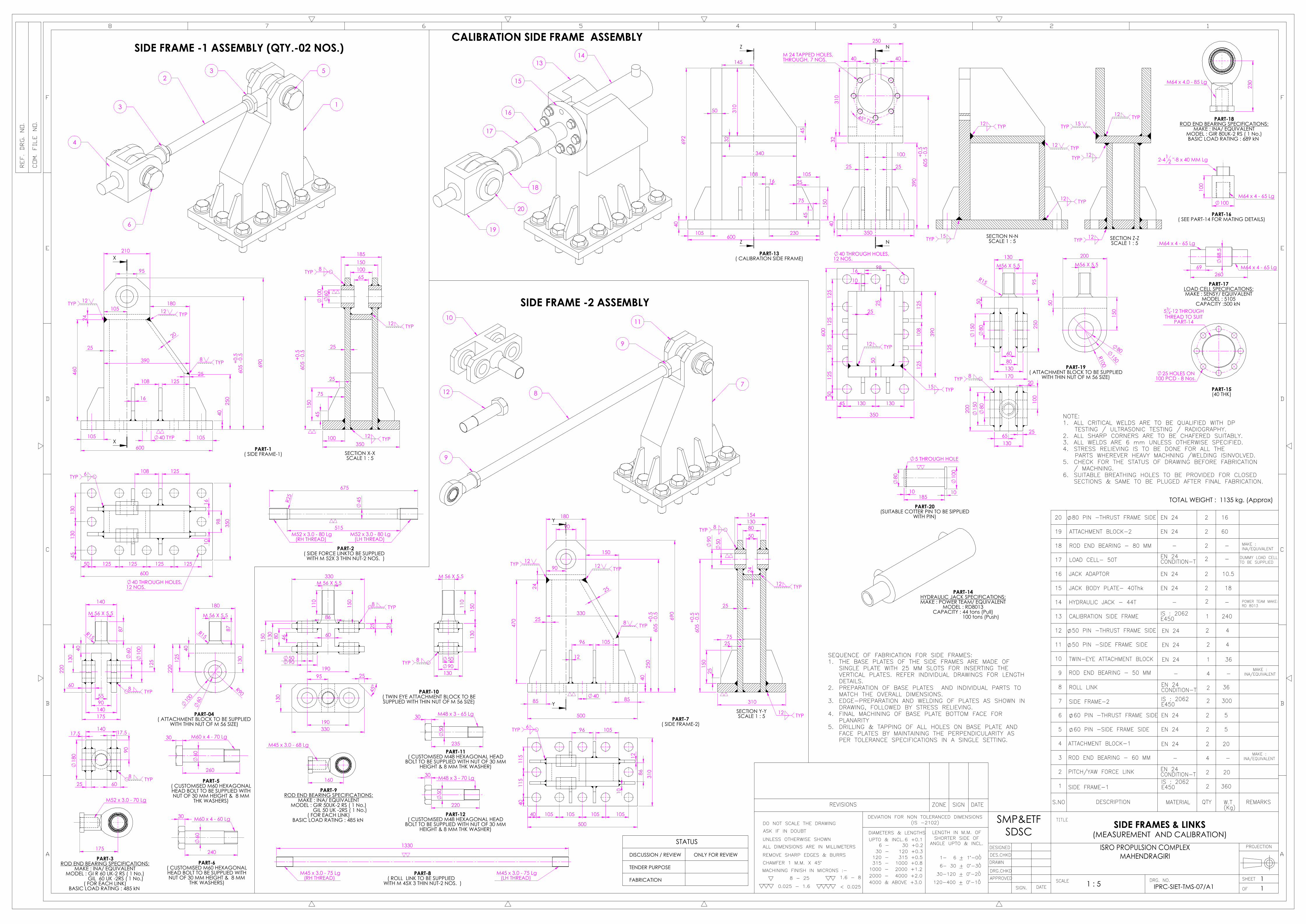
A
B
C
D
E
REF. DRG. NO.
COM. FILE NO.
F
8 7 6 5
S.NO
< 0.025
1.6 - 8
0.025 - 1.6
ASK IF IN DOUBT
ALL DIMENSIONS ARE IN MILLIMETERS
UNLESS OTHERWISE SHOWN
DO NOT SCALE THE DRAWING
8 - 25
MACHINING FINISH IN MICRONS :-
CHAMFER 1 M.M. X 45°
REMOVE SHARP EDGES & BURRS
120-400 + 0°-10 4000 & ABOVE +3.0 _SIGN. DATE
LENGTH IN M.M. OFSHORTER SIDE OF
ANGLE UPTO & INCL.
DEVIATION FOR NON TOLERANCED DIMENSIONS
30-120 + 0°-20
1- 6 + 1°-00
6- 30 + 0°-30
DIAMETERS & LENGTHS
6 - 30 +0.2
120 - 315 +0.5 315 - 1000 +0.8 1000 - 2000 +1.2 2000 - 4000 +2.0
30 - 120 +0.3
UPTO & INCL.
(IS -2102)
6 +0.1
DESIGNED
SMP&ETFSDSC
DES.CHKD
APPROVED
DRG.CHKD_
_
_DRAWN,
,
,
,
REMARKS
PROJECTION
SHEETDRG. NO.SCALE
OF
(MEASUREMENT AND CALIBRATION) ISRO PROPULSION COMPLEX
MAHENDRAGIRI
TITLE
DESCRIPTION QTYMATERIAL W.T(Kg)
A
B
C
4 3 2
D
E
1
F
675
515
45
R25
M52 x 3.0 - 80 Lg (RH THREAD)
M52 x 3.0 - 80 Lg (LH THREAD)
PART-2( SIDE FORCE LINKTO BE SUPPLIED
WITH M 52X 3 THIN NUT-2 NOS. )
175
M52 x 3.0 - 70 Lg
PART-3ROD END BEARING SPECIFICATIONS:
MAKE : INA/ EQUIVALENTMODEL : GI R 60 UK-2 RS ( 1 No.)
GIL 60 UK -2RS ( 1 No.)( FOR EACH LINK)
BASIC LOAD RATING : 485 kN
1330
M45 x 3.0 - 75 Lg(RH THREAD)
M45 x 3.0 - 75 Lg(LH THREAD)
PART-8( ROLL LINK TO BE SUPPLIED
WITH M 45X 3 THIN NUT-2 NOS. )
160
M45 x 3.0 - 68 Lg
PART-9ROD END BEARING SPECIFICATIONS:
MAKE : INA/ EQUIVALENTMODEL : GIR 50UK-2 RS ( 1 No.)
GIL 50 UK -2RS ( 1 No.)( FOR EACH LINK)
BASIC LOAD RATING : 485 kN
60
30
260
PART-5( CUSTOMISED M60 HEXAGONAL HEAD BOLT TO BE SUPPLIED WITH NUT OF 30 MM HEIGHT & 8 MM
THK WASHERS)
M60 x 4 - 70 Lg
50
235
30
PART-11( CUSTOMISED M48 HEXAGONAL HEAD
BOLT TO BE SUPPLIED WITH NUT OF 30 MM HEIGHT & 8 MM THK WASHER)
M48 x 3 - 65 Lg
80
100
10 10 185
5 THROUGH HOLE
PART-20(SUITABLE COTTER PIN TO BE SIPPLIED
WITH PIN)
230
PART-18ROD END BEARING SPECIFICATIONS:
MAKE : INA/ EQUIVALENTMODEL : GIR 80UK-2 RS ( 1 No.)BASIC LOAD RATING : 689 kN
M64 x 4.0 - 85 Lg
260
88.5
69
PART-17LOAD CELL SPECIFICATIONS:MAKE : SENSY/ EQUIVALENT
MODEL : 5105CAPACITY :500 kN
M64 x 4 - 65 Lg
M64 x 4 - 65 Lg
100
100
2-412 "-8 x 40 MM Lg
M64 x 4 - 65 Lg
PART-16( SEE PART-14 FOR MATING DETAILS)
534-12 THROUGH
THREAD TO SUIT PART-14
PART-15(40 THK)
25 HOLES ON 100 PCD - 8 Nos.
1
532
3
6
4
SIDE FRAME -1 ASSEMBLY (QTY.-02 NOS.)
30
240
60
PART-6( CUSTOMISED M60 HEXAGONAL HEAD BOLT TO BE SUPPLIED WITH NUT OF 30 MM HEIGHT & 8 MM
THK WASHERS)
M60 x 4 - 60 Lg
M 56 X 5.5
140
87
R15
40
100
60
125
130
60
140 90 55
175
220
PART-04( ATTACHMENT BLOCK TO BE SUPPLIED
WITH THIN NUT OF M 56 SIZE)
8 TYP
M 56 X 5.5
87
R15
180
40
125
2
20 130
R90
100
60
140
180 9
0
25 60
17.5 17.5
8 TYP
605
+ -0.5
0.5
690
40
25
460
24
25
20
16
108 125
105 105
250
40 TYP
600
390
210
95
180 105
X
XPART-1
( SIDE FRAME-1)
12TYP12 TYP
8 TYP
600
350
16
98
125 108
130
1
30
45
50 125 125 125 125
10
40 THROUGH HOLES,12 NOS.
6TYP
605
+ -0.5
0.5
185 150 100 65
60
100
100 350
25
150
4
5
75
25
SECTION X-XSCALE 1 : 5
8TYP
12 TYP
12 TYP
78
9
9
11
SIDE FRAME -2 ASSEMBLY 10
12
180
90 2
4
470
605
+ -0.5
0.5
690
150
25
25 330
40
250
85
500
85 40
12
96 105
90
Y
Y
PART-7( SIDE FRAME-2)
12TYP 12 TYP
8 TYP
605
+ -0.5
0.5
50 90 50
80 130 154
25
24
310 2
5
75 25
150
SECTION Y-YSCALE 1 : 5
8TYP
12 TYP
12 TYP
310
500
40 105 105 105 105
40
115
1
15
12
86
10
105 96 6TYP
M 56 X 5.5 330
190
150
1
30
80
46
25
25
86
110
150
60
50 90
PART-10( TWIN EYE ATTACHMENT BLOCK TO BE SUPPLIED WITH THIN NUT OF M 56 SIZE)
8 TYP
M 56 X 5.5
110
150
1
30
130 90 50 8 TYP
330
130
190
25
45°
95
30
50
220
PART-12( CUSTOMISED M48 HEXAGONAL HEAD
BOLT TO BE SUPPLIED WITH NUT OF 30 MM HEIGHT & 8 MM THK WASHER)
M48 x 3 - 70 Lg
CALIBRATION SIDE FRAME ASSEMBLY
15
16
17
18
19
20
1314
250
50 40 40
310
3
2
605
+ -0.5
0.5
390
40
25 25
100
350
45° TYP
N
N
M 24 TAPPED HOLES, THROUGH, 7 NOS.
692
4
0
600
50 310
3
2
340
145
45
25
150
45
75
105
230
16 108
105
Z
Z
PART-13( CALIBRATION SIDE FRAME)
SECTION Z-ZSCALE 1 : 5
12TYP
15TYP
12 TYP
12TYP
350
600
45 130 130
50
125
1
25
125
1
25
16
10
98
125
1
08
125
390
50
25
25
40 THROUGH HOLES,12 NOS.
15 TYP
12 TYP
SECTION N-NSCALE 1 : 5
12 TYP
15TYP
12 TYP
12 TYP
M56 X 5.5
200
150
50
80
150
R100 PART-19( ATTACHMENT BLOCK TO BE SUPPLIED
WITH THIN NUT OF M 56 SIZE)
M56 X 5.5 130
95 R15
60 80 130 170
80
150
250
50
130
200
100
65
80
150
25
20 8TYP
PART-14HYDRAULIC JACK SPECIFICATIONS:MAKE : POWER TEAM/ EQUIVALENT
MODEL : RD8013CAPACITY : 44 tons (Pull)
100 tons (Push)
1 SIDE FRAME-1 2
2
3
4
5
6
7
8
SIDE FRAMES & LINKS
1 : 5 IPRC-SIET-TMS-07/A1 11
360
TOTAL WEIGHT : 1135 kg. (Approx)
REVISIONS SIGNZONE DATE
ATTACHMENT BLOCK-1
ROD END BEARING - 60 MM
PITCH/YAW FORCE LINK
2
4
2
20
20
IS : 2062E450
DISCUSSION / REVIEW
FABRICATION
TENDER PURPOSE
STATUS
MAKE : INA/EQUIVALENT
EN 24
NOTE:ALL CRITICAL WELDS ARE TO BE QUALIFIED WITH DP1.TESTING / ULTRASONIC TESTING / RADIOGRAPHY.ALL SHARP CORNERS ARE TO BE CHAFERED SUITABLY.2.ALL WELDS ARE 6 mm UNLESS OTHERWISE SPECIFIED.3.STRESS RELIEVING IS TO BE DONE FOR ALL THE4.PARTS WHEREVER HEAVY MACHNING /WELDING ISINVOLVED.CHECK FOR THE STATUS OF DRAWING BEFORE FABRICATION5./ MACHNING.SUITABLE BREATHING HOLES TO BE PROVIDED FOR CLOSED6.SECTIONS & SAME TO BE PLUGED AFTER FINAL FABRICATION.
EN 24CONDITION-T
60 PIN -SIDE FRAME SIDE EN 24 2
2 5
5
13
12
11
10
9
CALIBRATION SIDE FRAME 1
15
14
JACK BODY PLATE- 40Thk
HYDRAULIC JACK - 44T
EN 24 2
2
17
16
LOAD CELL- 50T
JACK ADAPTOR 2
POWER TEAM MAKE:RD 8013
18 - 2
-
18
10.5
-
20
19 ATTACHMENT BLOCK-2
EN 24
EN 24
2
2
16
60
SEQUENCE OF FABRICATION FOR SIDE FRAMES:THE BASE PLATES OF THE SIDE FRAMES ARE MADE OF1.SINGLE PLATE WITH 25 MM SLOTS FOR INSERTING THEVERTICAL PLATES. REFER INDIVIDUAL DRAWINGS FOR LENGTHDETAILS.PREPARATION OF BASE PLATES AND INDIVIDUAL PARTS TO2.MATCH THE OVERALL DIMENSIONS.EDGE-PREPARATION AND WELDING OF PLATES AS SHOWN IN3.DRAWING, FOLLOWED BY STRESS RELIEVING.FINAL MACHINING OF BASE PLATE BOTTOM FACE FOR4.PLANARITYDRILLING & TAPPING OF ALL HOLES ON BASE PLATE AND5.FACE PLATES BY MAINTAINING THE PERPENDICULARITY ASPER TOLERANCE SPECIFICATIONS IN A SINGLE SETTING.
- -
60 PIN -THRUST FRAME SIDE EN 24
EN 2450 PIN -THRUST FRAME SIDE
--
4
42
2EN 2450 PIN -SIDE FRAME SIDE
EN 24CONDITION-T
EN 24
MAKE : INA/EQUIVALENT
36
36
2
4
1
ROLL LINK
ROD END BEARING - 50 MM
TWIN-EYE ATTACHMENT BLOCK
3002IS : 2062E450SIDE FRAME-2
IS : 2062E450
-
EN 24
DUMMY LOAD CELL TO BE SUPPLIED
-2
ROD END BEARING - 80 MM MAKE : INA/EQUIVALENT
80 PIN -THRUST FRAME SIDE
ONLY FOR REVIEW
240
EN 24CONDITION-T
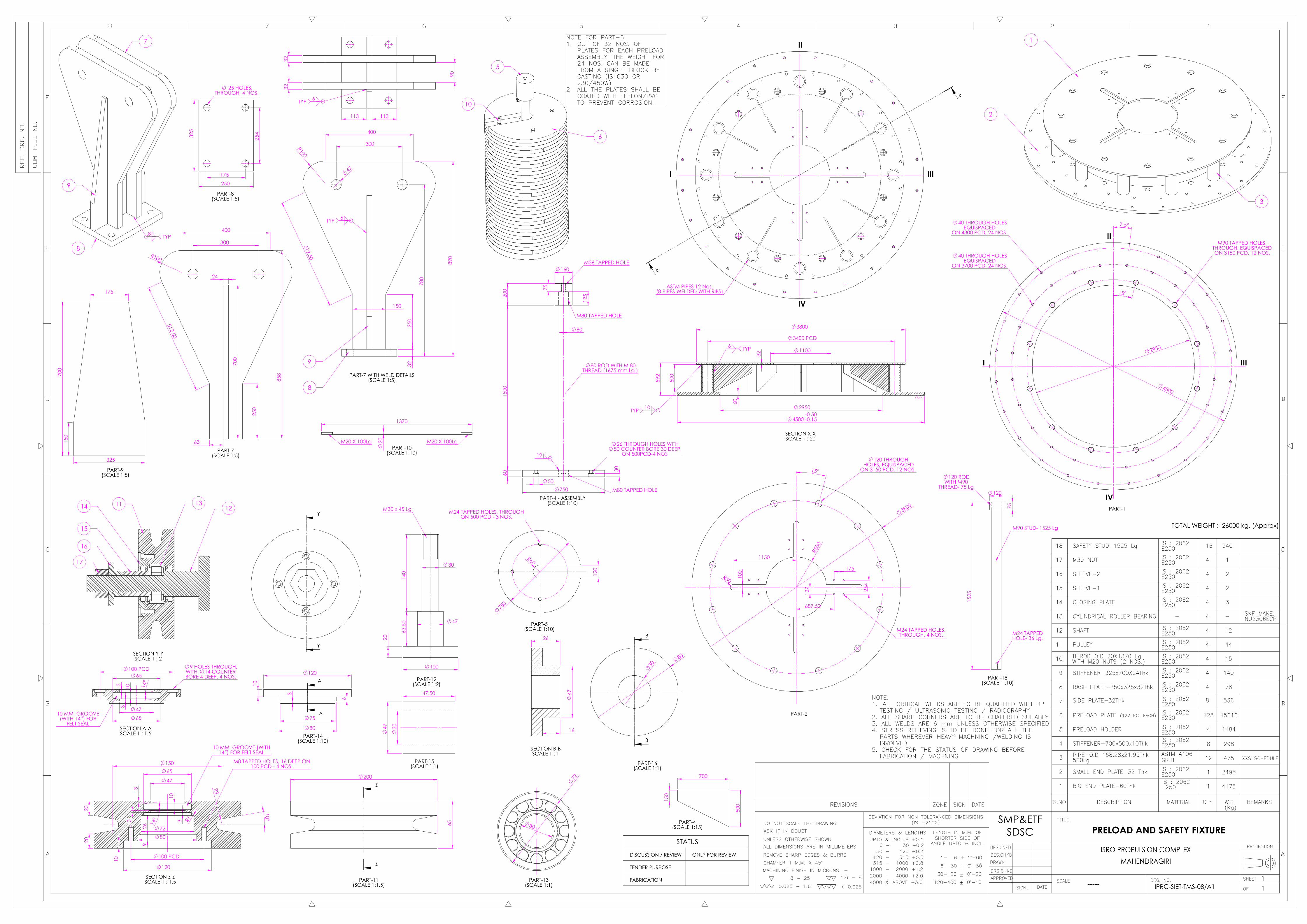
A
B
C
D
E
REF. DRG. NO.
COM. FILE NO.
F
8 7 6 5
S.NO
< 0.025
1.6 - 8
0.025 - 1.6
ASK IF IN DOUBT
ALL DIMENSIONS ARE IN MILLIMETERS
UNLESS OTHERWISE SHOWN
DO NOT SCALE THE DRAWING
8 - 25
MACHINING FINISH IN MICRONS :-
CHAMFER 1 M.M. X 45°
REMOVE SHARP EDGES & BURRS
120-400 + 0°-10 4000 & ABOVE +3.0 _SIGN. DATE
LENGTH IN M.M. OFSHORTER SIDE OF
ANGLE UPTO & INCL.
DEVIATION FOR NON TOLERANCED DIMENSIONS
30-120 + 0°-20
1- 6 + 1°-00
6- 30 + 0°-30
DIAMETERS & LENGTHS
6 - 30 +0.2
120 - 315 +0.5 315 - 1000 +0.8 1000 - 2000 +1.2 2000 - 4000 +2.0
30 - 120 +0.3
UPTO & INCL.
(IS -2102)
6 +0.1
DESIGNED
SMP&ETFSDSC
DES.CHKD
APPROVED
DRG.CHKD_
_
_DRAWN,
,
,
,
REMARKS
PROJECTION
SHEETDRG. NO.SCALE
OF
ISRO PROPULSION COMPLEXMAHENDRAGIRI
TITLE
DESCRIPTION QTYMATERIAL W.T(Kg)
A
B
C
4 3 2
D
E
1
F
2
1
3
7.5°
15°
4500
2950
40 THROUGH HOLES EQUISPACED
ON 3700 PCD, 24 NOS.
40 THROUGH HOLES EQUISPACED
ON 4300 PCD, 24 NOS.
M90 TAPPED HOLES, THROUGH, EQUISPACEDON 3150 PCD, 12 NOS.
15°
3800
R50 100
1150
175
254
687.50
127
R
550
120 THROUGH HOLES, EQUISPACED
ON 3150 PCD, 12 NOS.
M24 TAPPED HOLES,THROUGH, 4 NOS.
X
X
ASTM PIPES 12 Nos.(8 PIPES WELDED WITH RIBS)
IV
III
II
I
592
500
4500 --0.500.15
3800
2950
1100
60
32
3400 PCD
SECTION X-XSCALE 1 : 20
6 TYP
10TYP
700
500
150
750
60
150
0 2
00
160
80
75
30
50
125
M36 TAPPED HOLE
M80 TAPPED HOLE
M80 TAPPED HOLE
80 ROD WITH M 80 THREAD (1675 mm Lg.)
26 THROUGH HOLES WITH 50 COUNTER BORE 30 DEEP,
ON 500PCD-4 NOS12
5
6
NOTE FOR PART-6:OUT OF 32 NOS. OF1.PLATES FOR EACH PRELOADASSEMBLY. THE WEIGHT FOR24 NOS. CAN BE MADEFROM A SINGLE BLOCK BYCASTING (IS1030 GR230/450W)ALL THE PLATES SHALL BE2.COATED WITH TEFLON/PVCTO PREVENT CORROSION.10
120
R60
750
M24 TAPPED HOLES, THROUGH ON 500 PCD - 3 NOS.
8
9
7
8 TYP
Y
YSECTION Y-YSCALE 1 : 2
1112
1314
15
16
17
325
175
254
250
PART-8(SCALE 1:5)
25 HOLES,THROUGH, 4 NOS.
90
32
32
113 113
6TYP
780
890
47
300 R100
400
32
150
512.50
250
9
8
6TYP
65
200 Z
Z
72
R8
10°
20
20
150 65
47
10
14°
3
3
80
120
100 PCD
3
R1
26
9
10
SECTION Z-ZSCALE 1 : 1.5
M8 TAPPED HOLES, 16 DEEP ON 100 PCD - 4 NOS.
10 MM GROOVE (WITH 14 ) FOR FELT SEAL
30
140
100
20 6
3.50
47
M30 x 45 Lg
PART-12(SCALE 1:2)
120
10
80
75
6 3
A
A
100 PCD 65
65
10
3
3
47
14°
SECTION A-ASCALE 1 : 1.5
9 HOLES THROUGH, WITH 14 COUNTER BORE 4 DEEP, 4 NOS.
10 MM GROOVE (WITH 14 ) FOR
FELT SEAL
72
30
47
30
47.50
80 30
B
B
PART-16(SCALE 1:1)
26
16
47
SECTION B-BSCALE 1 : 1
152
5
120
75
120 ROD WITH M90
THREAD- 75 Lg
M90 STUD- 1525 Lg
M24 TAPPED HOLE- 36 Lg.
325
150
175
700
PART-9(SCALE 1:5)
400
R100
512.50
24
63
250
300
858
700
PART-7(SCALE 1:5)
1370
20
PART-10(SCALE 1:10)
M20 X 100Lg M20 X 100Lg
1 BIG END PLATE-60Thk 1
2
3
4
5
6
7
8
PRELOAD AND SAFETY FIXTURE
----- IPRC-SIET-TMS-08/A1 11
4175
TOTAL WEIGHT : 26000 kg. (Approx)
REVISIONS SIGNZONE DATE
STIFFENER-700x500x10Thk
PIPE-O.D 168.28x21.95Thk500Lg
SMALL END PLATE-32 Thk
8
12
1
298
475
2495
ASTM A106GR.B
IS : 2062E250
DISCUSSION / REVIEW
FABRICATION
TENDER PURPOSE
STATUS
PART-2
XXS SCHEDULE
IS : 2062E250
NOTE:ALL CRITICAL WELDS ARE TO BE QUALIFIED WITH DP1.
TESTING / ULTRASONIC TESTING / RADIOGRAPHY2. ALL SHARP CORNERS ARE TO BE CHAFERED SUITABLY3. ALL WELDS ARE 6 mm UNLESS OTHERWISE SPECIFIED4. STRESS RELIEVING IS TO BE DONE FOR ALL THE PARTS WHEREVER HEAVY MACHNING /WELDING IS INVOLVED5. CHECK FOR THE STATUS OF DRAWING BEFORE FABRICATION / MACHNING
PART-1
IV
I III
II
PART-4(SCALE 1:15)
IS : 2062E250
PRELOAD HOLDER IS : 2062E250 4
PART-4 - ASSEMBLY(SCALE 1:10)
PART-5(SCALE 1:10)
PRELOAD PLATE (122 KG. EACH) IS : 2062E250 128 15616
1184
SIDE PLATE-32Thk IS : 2062E250
IS : 2062E250 4
8
PART-7 WITH WELD DETAILS(SCALE 1:5)
13
12
11
10
9
CYLINDRICAL ROLLER BEARING
SHAFT
PULLEY
STIFFENER-325x700X24Thk
IS : 2062E250
IS : 2062E250
IS : 2062E250
IS : 2062E250
4
4
4
4
4
15
14
SLEEVE-1
CLOSING PLATE
IS : 2062E250
IS : 2062E250
4
4
17
16
M30 NUT
SLEEVE-2
IS : 2062E250
IS : 2062E250
4
4
PART-14(SCALE 1:10)
PART-11(SCALE 1:1.5)
PART-13(SCALE 1:1)
PART-15(SCALE 1:1)
PART-18(SCALE 1 :10)
536
BASE PLATE-250x325x32Thk 78
140
15TIEROD O.D 20X1370 Lg WITH M20 NUTS (2 NOS.)
44
12
SKF MAKE:NU2306ECP--
SAFETY STUD-1525 Lg18 IS : 2062E250 16
3
2
2
1
940
ONLY FOR REVIEW

A
B
C
D
E
REF. DRG. NO.
COM. FILE NO.
F
8 7 6 5
S.NO
< 0.025
1.6 - 8
0.025 - 1.6
ASK IF IN DOUBT
ALL DIMENSIONS ARE IN MILLIMETERS
UNLESS OTHERWISE SHOWN
DO NOT SCALE THE DRAWING
8 - 25
MACHINING FINISH IN MICRONS :-
CHAMFER 1 M.M. X 45°
REMOVE SHARP EDGES & BURRS
120-400 + 0°-10 4000 & ABOVE +3.0 _SIGN. DATE
LENGTH IN M.M. OFSHORTER SIDE OF
ANGLE UPTO & INCL.
DEVIATION FOR NON TOLERANCED DIMENSIONS
30-120 + 0°-20
1- 6 + 1°-00
6- 30 + 0°-30
DIAMETERS & LENGTHS
6 - 30 +0.2
120 - 315 +0.5 315 - 1000 +0.8 1000 - 2000 +1.2 2000 - 4000 +2.0
30 - 120 +0.3
UPTO & INCL.
(IS -2102)
6 +0.1
DESIGNED
SMP&ETFSDSC
DES.CHKD
APPROVED
DRG.CHKD_
_
_DRAWN,
,
,
,
REMARKS
PROJECTION
SHEETDRG. NO.SCALE
OF
ISRO PROPULSION COMPLEXMAHENDRAGIRI
TITLE
DESCRIPTION QTYMATERIAL W.T(Kg)
A
B
C
4 3 2
D
E
1
F
30° TYP
7.5° 15° TYP 15°
30° TYP
700
700
XX
42 THROUGH HOLEEQUISPACED ON 4300PCD 24 NOS.42 THROUGH HOLE
EQUISPACED ON 3700 PCD 24 NOS.
20 THROUGH HOLEEQUISPACED ON 4000 PCD 12 NOS.
M 48 TAPPED HOLES,80 DEEP - 4 NOS.
10 TYP
60°
1790
590
65
150
4500 --0.500.75
3500
241
8
50
146.40
30°
265
8.6
90°
168.28
21.95
1350 PCD
3960 PCD
2610
SECTION X-XSCALE 1 : 15
0.2 A
A
15 TYP
15 TYP
1
3
4
2 CALIBRATION FRAME
865
188
261
5
261
5
PART-04(12 Thk.)
56
7
8
9
10
CALIBRATION PLATE
112
TYP
70 TYP
30° TYP
R830
R740
20° TYP
12°
TYP
32
R780 57°
57°
YY
22 THROUGH HOLEON 1560 PCD -12 NOS.
M250X 4 250
500
1800
80
560
80
800
700 15
20
SECTION Y-YSCALE 1 : 15
15 TYP
15 TYP
10 TYP
8 TYP
8 TYP
45° TYP 32
16° TYP
M 24 TAPPED HOLES,ON 600 PCD,48 DEEP - 8 NOS.
45° TYP
ZZ
M 24 TAPPED HOLES,ON 600 PCD,48 DEEP - 8 NOS.
M250X 4 500
480
250
80
800 700
15
SECTION Z-ZSCALE 1 : 15
PART-06
400
350
130
20
PART-07
32
400
500
20
80
PART-08
32
80
R740
R830
112 12°
22
R780
PART-10SCALE 1:5
20
70
20°
R830
R740
22
R780
PART-9SCALE 1:5
20
N
N
M 36 TAPPED HOLES,ON 440 PCD,55 DEEP,EQUISPACED-12 NOS.
JACK ADAPTOR(PART-11)
540
M 3
50 X
4
500
440
PC
D
SECTION N-NSCALE 1 : 10
10 X 45 CHAMFER
P
P
BEARING HOUSING(PART-12)
40 THROUGH HOLES, ON 440 PCD,36 DEEP, EQUISPACED-12 NOS.
54
0
120
340
+0.0
40
440
PC
D
259
40
SECTION P-PSCALE 1 : 10
265
Q
Q
INSITU CALIBRATION LINK(PART-13)
100
1175
M 1
25 X
4
150
265
200
- -0.05
0.07
SECTION Q-QSCALE 1 : 10 5 X 45 CHAMFER
190
R
R
300T LOAD CELL(PART-14)
LOAD CELL SPECIFICATIONS:MAKE : SENSY/ EQUIVALENT
MODEL : 5105CAPACITY :3 MN
M 1
25 X
4- 1
35 L
M 1
25 X
4 -1
35 L
440 140 160
190
SECTION R-RSCALE 1 : 10
250
T
T
3375 150
250
270
M 2
50 X
4
M12
5 X4
SECTION T-TSCALE 1 : 10INSITU CALIBRATION TIE ROD
(PART-15)
M350 X 4
350
100
680
335
(SCALE 1 : 15)
(PART-16)HYDRAULIC JACK SPECIFICATIONS:
MAKE :LARZEP/ EQUIVALENTMODEL : TD100015/C ( 1 No.)
CAPACITY : 985 t (PULL)STROKE : 150 MM
1000T HYDAULIC JACK (AT MID STROKE)
900
900
700
700
R100
B
B
AXIAL SPHERICAL PLAIN BEARING(PART-17)
ROD END BEARING SPECIFICATIONS:MAKE : INA/ EQUIVALENT
MODEL : GE 200 AW ( 1 No.)BASIC LOAD RATING : 7100 kN
87 60
200
246
SECTION B-BSCALE 1 : 10
6
4500
400
7.5° 15° TYP
30° TYP
15° TYP
SS
42 THROUGH HOLEEQUISPACED ON 3700 PCD 24 NOS.
M 16 TAPPED THROUGH HOLEEQUISPACED ON 4000 PCD 12 NOS.
42 THROUGH HOLEEQUISPACED ON 4300PCD 24 NOS.
6 MM Thk RIBS,24 NOS.
3 TYP
6
50
100
1530
400
4500
SECTION S-SSCALE 1 : 20
WORKING PLATFORM(PART-18)
6 MM THK CHQ PLATE
1 1
2
CALIBRATION SYSTEM
1 : 15 IPRC-SIET-TMS-09/A1 11
2425
REVISIONS SIGNZONE DATE
1 1900
IS : 2062E250
DISCUSSION / REVIEW
FABRICATION
TENDER PURPOSE
STATUS
BIG END PLATE
SMALL END RING IS : 200420C8
TOTAL WEIGHT : 13115 kg. (Approx)
17
16
15
14
13
12
11
10
9
8
7
6
5
4
3
AXIAL SPHERICAL PLAIN BEARING
1000 T HYDAULIC JACK
INSITU CALIBRATION TIE ROD
LOAD CELL - 3 MN
INSITU CALIBRATION LINK
BEARING HOUSING
JACK ADAPTOR
PAD-2
PAD-1
STIFFENER -400X350X32Thk
END BLOCK
PLATE- O.D 1800 X 80 Thk.
STIFFENER-2615X 865X16Thk.
PIPE O.D 168.28X21.95ThK.2610-Lg.
IS : 2062E250
EN 24CONDITION-T
EN 24
EN 24
EN 24
EN 24
IS : 2062E250
IS : 2062E250
IS : 2062E250
EN 24(ANNEALED)
IS : 2062E250
ASTM A 106GR. B
1
1
1
1
1
1
1
4
2
22
12
1
1
3
12
35
1920
1275
-
290
135
510
11
10
130
300
908
1450
375
2475 XXS SCHEDULE
NOTE:ALL CRITICAL WELDS ARE TO BE QUALIFIED WITH DP1.
TESTING / ULTRASONIC TESTING / RADIOGRAPHY2. ALL SHARP CORNERS ARE TO BE CHAFERED SUITABLY3. ALL WELDS ARE 6 mm UNLESS OTHERWISE SPECIFIED4. STRESS RELIEVING IS TO BE DONE FOR ALL THE PARTS WHEREVER HEAVY MACHNING /WELDING IS INVOLVED5. CHECK FOR THE STATUS OF DRAWING BEFOREFABRICATION/MACHNING
STIFFENER -500X80X32Thk
EN 24
MAKE:LARZEP / EQUIVALENT
MAKE:INA / EQUIVALENT
ONLY FOR REVIEW
SEQUENCE OF FABRICATION FOR CALIBRATION FRAME:PREPARATION OF PART-1 BY WELDING FROM MULTIPLE PLATES. PART-02 IS FORGED.1.PRE-MACHINING OF PART-1 AND PART-22.WELDING OF PART 3, PART-4 AFTER ENSURING GAPS BETWEEN PIPES, FOLLOWED BY3.STRESS RELIEVINGFINAL MACHINING OF PART-1 AND PART-4 END FACES FOR PLANARITY4.DRILLING & TAPPING OF ALL INTERFACE HOLES ON END FACES AS PER TOLERANCE5.SPECIFICATIONS IN A SINGLE SETTING.
DUMMY LOAD CELL TO BE SUPPLIED
8651WORKING PLATFORM18 IS : 2062E250

A
B
C
D
E
REF. DRG. NO.
COM. FILE NO.
F
8 7 6 5
S.NO
< 0.025
1.6 - 8
0.025 - 1.6
ASK IF IN DOUBT
ALL DIMENSIONS ARE IN MILLIMETERS
UNLESS OTHERWISE SHOWN
DO NOT SCALE THE DRAWING
8 - 25
MACHINING FINISH IN MICRONS :-
CHAMFER 1 M.M. X 45°
REMOVE SHARP EDGES & BURRS
120-400 + 0°-10 4000 & ABOVE +3.0 _SIGN. DATE
LENGTH IN M.M. OFSHORTER SIDE OF
ANGLE UPTO & INCL.
DEVIATION FOR NON TOLERANCED DIMENSIONS
30-120 + 0°-20
1- 6 + 1°-00
6- 30 + 0°-30
DIAMETERS & LENGTHS
6 - 30 +0.2
120 - 315 +0.5 315 - 1000 +0.8 1000 - 2000 +1.2 2000 - 4000 +2.0
30 - 120 +0.3
UPTO & INCL.
(IS -2102)
6 +0.1
DESIGNED
SMP&ETFSDSC
DES.CHKD
APPROVED
DRG.CHKD_
_
_DRAWN,
,
,
,
REMARKS
PROJECTION
SHEETDRG. NO.SCALE
OF
ISRO PROPULSION COMPLEXMAHENDRAGIRI
TITLE
DESCRIPTION QTYMATERIAL W.T(Kg)
A
B
C
4 3 2
D
E
1
F
1
3
4
2
INTERFACE FRAME
A
A
PIPE - OD 168.28 WITH 21.95 THK & STINFFENER WELDED (15 MM Thk FILLET WELD) AT 6 LOCATIONS, EQUISPACED
ON 3962 PCD
3500
3400
4500
4500
4750
4750
60
60
750
20
SECTION A-ASCALE 1 : 20
0.2 A
A
12 TYP
12TYP
6 TYP
5 7
6
8
9
250
0
40
40
130
0
NOTE: PART-8 TO BE MADE FROM MULTIPLE PLATE SEGMENTS1.
(PREFERABLY 2 NOS.) BY WELDING.2. PART-7 IS WELDED BETWEEN PART-6 BY BENDING INTO CIRCULAR ARC OF RADIUS 2000 MM. WELD SIZE IS 6 MM.
27.5°
45°
27.5°
45°
17.5
° 17.5°
57.
5°
32.5° 32.5°
57.5°
21°
18°
21°
18°
21° 21°
R22
50
R1750
7.5° TYP
R50
(TYP
)
140
1
20
IV
III
II
I
40 THROUGH HOLES ON 4300 PCD - 12 NOS
40 THROUGH HOLES ON 3700 PCD - 12 NOS
40 THROUGH HOLES ON 4000 PCD - 12 NOS
125
TYP
130 TYP
4500
2500
45° TYP
IV
III
II
I
M36 TAPPED HOLES, THROUGH (12 NOS) AS SHOWN, 8 SETS EQUISPACED ON 3100 PCD
240
5
250
M125 TAPPED HOLE- 140 Lg.
M250 x4 THREAD- 270 Lg
350
PART-10 - 48 THK(SCALE 1:5)
M56 x 5.5 TAPPED HOLE,THROUGH -1 NO.
25 HOLES EQUISPACED ON 280 PCD, THROUGH - 8 NOS.
SIDE LOAD SIMULATION FRAME(SCALE 1:5)
15
16
1718
1920
11
12
13
14ENGINE SPACER FRAME
(SCALE 1:10)
738
90
150
50
700
26 HOLES EQUISPACED ON 600 PCD, THROUGH - 8 NOS.
PART-14 - 32 THK(SCALE 1:5)
II
III
IV
I
C
C
M24 TAPPEDHOLES EQUISPACED ON 600 PCD,
THROUGH - 8 NOS.
I
II
III
IV
350
20
508
80
70
SECTION C-CSCALE 1 : 5
190
340
PART-19 ( 25 THK)
50
282
1
50
150
50
250
310
M24 TAPPED HOLES EQUISPACED ON 200 PCD,
THROUGH - 7 NOS.
PART-17 ( 50 THK)
50
250
250
50
PART-9 ( 16 THK)
900
70
M64
x4.0
90
PART- 22(SCALE 1 :10)
2-412 -40 Lg
1 FIXED FRAME INTERFACE PLATE 1
2
3
4
5
6
7
8
INTERFACE FRAME AND LOAD TEST FIXTURES
1 : 20 IPRC-SIET-TMS-10/A1 11
3500
TOTAL WEIGHT : 15750 kg. (Approx)
REVISIONS SIGNZONE DATE
STIFFENER-750x525x20Thk
PIPE-O.D 168.28x21.95Thk750Lg
CALIBRATION INTERFACE PLATE
6
12
1
742
712
2800
ASTM A106GR.B
IS : 2062E250
DISCUSSION / REVIEW
FABRICATION
TENDER PURPOSE
STATUS
XXS SCHEDULE
IS : 2062E250
NOTE:ALL CRITICAL WELDS ARE TO BE QUALIFIED WITH DP1.
TESTING / ULTRASONIC TESTING / RADIOGRAPHY2. ALL SHARP CORNERS ARE TO BE CHAFERED SUITABLY3. ALL WELDS ARE 6 mm UNLESS OTHERWISE SPECIFIED4. STRESS RELIEVING IS TO BE DONE FOR ALL THE PARTS WHEREVER HEAVY MACHNING /WELDING IS INVOLVED5. CHECK FOR THE STATUS OF DRAWING BEFORE FABRICATION / MACHNING
IV
I III
II
PART-13(SCALE 1:5)
IS : 2062E250
SUPPORT PLATES - 6 Nos. IS : 2062E250 1 SET
PART-8(SCALE 1:20)
ISMC 400, 2500Long (BOX SECTION)
IS : 2062E250 6 1500
635
BASE PLATE-40Thk
IS : 4923Yst 310
IS : 2062E250
1
SUPPORT STOOL
PART-5(LOCATION DETAILS OF ISMC 400 WITH SUPPORT PLATES)
13
12
11
10
9
STIFFENER-738x90x16Thk
PIPE OD-508MMX50.1Thk -658MM Lg
TOP PLATE-80Thk
ASTM A 106
IS : 2062E250
IS : 2062E250
IS : 2062E250
8
1
1
1
1
15
14
BOTTOM PLATE-40Thk
BOTTOM PLATE-32Thk
IS : 2062E250
IS : 2062E250
1
1
17
16
FACING PLATE-50Thk
STIFFENER
IS : 2062E250
IS : 2062E250
1
8
PART- 21(SCALE 1 :10)
3400
35BLOCK PLATE-48Thk
110
360
SIDE PLATE18 IS : 2062E250 2
95
REFER IPRC/SIET/TMS-06/A1-PART2
REFER IPRC/SIET/TMS-06/A1-PART1
STIFFENER-250x250x16Thk
LOAD TEST TIEROD-1
PART-11 NOTE:ALL THE PARTS 15,16,18 &20 AND WELDING1.SCHEME IS IDENTICAL TO CALIBRATION SIDEFRAME(REFER IPRC/SIET/TMS-07 FORDETAILS). AFTER WELDING THE CENTREHEIGHT OF THE HYDRAULIC JACK WILL BE350 MM INSTEAD OF 605 MM.
SHS 200x200x6Thk-12500LONG
48 78
20
19
CLOSING PLATE
PLATE-340x190x25Thk
IS : 2062E250
IS : 2062E250
1
2
21 1IS : 2062E250 906
740
NOTE:PART-12 ISCOCENTICALLY WELDED WITH PART 14.1.WELD SIZE IS 15 MM.PART 11 IS WELDED ON THE TOP OF PART 12 ON2.THE PERIPHERY AS AN EDGE JOINT. WELD SIZE IS15 MM.PART-13 IS WELDED AS LENGTHWISE STIFFENER WITH3.PART 11 AND PART 12. WELD SIZE IS 6 MM.
IS : 2062E250 82
185REFER IPRC/SIET/TMS-07/A1-PART13 FOR COMPLETE DETAILS
441EN 24LOAD TEST TIEROD-222

A
B
C
D
E
REF. DRG. NO.
COM. FILE NO.
F
8 7 6 5
S.NO
< 0.025
1.6 - 8
0.025 - 1.6
ASK IF IN DOUBT
ALL DIMENSIONS ARE IN MILLIMETERS
UNLESS OTHERWISE SHOWN
DO NOT SCALE THE DRAWING
8 - 25
MACHINING FINISH IN MICRONS :-
CHAMFER 1 M.M. X 45°
REMOVE SHARP EDGES & BURRS
120-400 + 0°-10 4000 & ABOVE +3.0 _SIGN. DATE
LENGTH IN M.M. OFSHORTER SIDE OF
ANGLE UPTO & INCL.
DEVIATION FOR NON TOLERANCED DIMENSIONS
30-120 + 0°-20
1- 6 + 1°-00
6- 30 + 0°-30
DIAMETERS & LENGTHS
6 - 30 +0.2
120 - 315 +0.5 315 - 1000 +0.8 1000 - 2000 +1.2 2000 - 4000 +2.0
30 - 120 +0.3
UPTO & INCL.
(IS -2102)
6 +0.1
DESIGNED
SMP&ETFSDSC
DES.CHKD
APPROVED
DRG.CHKD_
_
_DRAWN,
,
,
,
REMARKS
PROJECTION
SHEETSCALE
OF
ISRO PROPULSION COMPLEXMAHENDRAGIRI
TITLE
DESCRIPTION QTYMATERIAL W.T(Kg)
A
B
C
4 3 2
D
E
1
F
28
29
30 262724
5
2
3
1
12
13
14
15
16
17
18
19
21
22
20
XX
9
11
5
30
23
3
10
12
SECTION X-XSCALE 1 : 15
1
2
3
4
5
6
8
10
12
13
14
16
17
18
19
20
21
22
23
24
26
25
27
28
30
29
15
LOAD TEST SETUP
1 : 15 IPRC-SIET-TMS-11/A1 11
REVISIONS SIGNZONE DATE
DISCUSSION / REVIEW
FABRICATION
TENDER PURPOSE
STATUS
NOTE:ALL CRITICAL WELDS ARE TO BE QUALIFIED WITH DP1.
TESTING / ULTRASONIC TESTING / RADIOGRAPHY2. ALL SHARP CORNERS ARE TO BE CHAFERED SUITABLY3. ALL WELDS ARE 6 mm UNLESS OTHERWISE SPECIFIED4. STRESS RELIEVING IS TO BE DONE FOR ALL THE PARTS WHEREVER HEAVY MACHNING /WELDING IS INVOLVED5. CHECK FOR THE STATUS OF DRAWING BEFORE FABRICATION / MACHNING
ONLY FOR REVIEW
------
EN24
------
EN24
IPRC-SIET-TMS-04
IPRC-SIET-TMS-05
IPRC-SIET-TMS-02
IPRC-SIET-TMS-10
IPRC-SIET-TMS-07
IPRC-SIET-TMS-07
IPRC-SIET-TMS-07
IPRC-SIET-TMS-07
IPRC-SIET-TMS-07
IPRC-SIET-TMS-07
IPRC-SIET-TMS-05
IPRC-SIET-TMS-07
IPRC-SIET-TMS-05
IPRC-SIET-TMS-09
IPRC-SIET-TMS-09
IPRC-SIET-TMS-09
IPRC-SIET-TMS-09
IPRC-SIET-TMS-09
IPRC-SIET-TMS-09
IPRC-SIET-TMS-10
IPRC-SIET-TMS-09
IPRC-SIET-TMS-09
IPRC-SIET-TMS-03
44T CALIBRATION JACK WITH LOADCELL AND ADAPTOR
ENGINE SPACER FRAME
SLS SPACER PLATE
LOAD TEST TIE ROD-2
30
---
510
110
290
---
906
830
2865
1
1
1
1
1
1
1
1
E250
E250
E250/EN24
EN24
IS : 2062
IS : 2062
IS : 2062
1000T HYDRAULIC JACK
HYDRAULIC JACK ADAPTOR
SPHERICAL BEARING & BEARING HOUSING
IN-SITU CALIBRATION LINK
300T LOAD CELL
LOAD TEST TIE ROD
WORKING PLATFORM
CALIBRATION PLATE
21
22
23
24
25
26
27
28
29
E250
EN 24
IS : 2062E450
E250
E450IS : 2062
E450IS : 2062
IS : 2062E250
E250IS : 2062
IS 2062:E250,IS 2004:20C8,ASTM A106 GR.BIS 2062:E250,IS 2004:20C8,ASTM A106 GR.B
EN 24
EN 24
EN 24
EN 24
CONDITION-T
CONDITION-T
CALIBRATION FRAME
19
20
EN 24
IS : 2062
IS : 2062
CONDITION-T
8315
7050
886
360
150
20
18
10
36
162
305
40
7175
1
1
3
1
2
1
2
1
1
1
3
1
8
1
FIXED FRAME
THRUST FRAME
AXIAL LINK ASSEMBLY
INTERFACE FRAME
SIDE FRAME-1
SIDE FRAME-2
PITCH FORCE/YAW FORCE LINK
ROLL LINK ASSEMBLY
ATTACHMENT BLOCK
ATTACHMENT BLOCK TWIN EYE
LATERAL SAFETY STOPPER
SIDE FORCE CALIBRATION LINKASSEMBLY
ALIGNMENT JACKS
1550
18
17
16
15
14
13
12
11
10
9
8
7
6
5
4
3
2
1SPACER FRAME1
ATTACHMENT BLOCK-2
SIDE LOAD SIMULATION FRAME
SUPPORT STOOL
1ASTM A 106 IPRC-SIET-TMS-10650
EN24
EN24
EN24
IS : 2062E450
------
E250IS : 2062
IPRC-SIET-TMS-10
IPRC-SIET-TMS-07
IPRC-SIET-TMS-10
IPRC-SIET-TMS-10
IPRC-SIET-TMS-07
IPRC-SIET-TMS-1035
30
1
1
1
1
1
1
44
183
---
6300