three phase ac ac hexagonal chopper system with …ieeeprojectsmadurai.com/2015-16 ieee papers/eee...
TRANSCRIPT

0885-8993 (c) 2013 IEEE. Personal use is permitted, but republication/redistribution requires IEEE permission. Seehttp://www.ieee.org/publications_standards/publications/rights/index.html for more information.
This article has been accepted for publication in a future issue of this journal, but has not been fully edited. Content may change prior to final publication. Citation information: DOI10.1109/TPEL.2014.2378018, IEEE Transactions on Power Electronics
1
Abstract—This paper proposes a three-phase AC chopper system
for the interconnection of various distributed generation (DG)
farms or main utilities to enhance the active and reactive power
flow control. The absence of large energy storage component in
direct AC-AC converter makes the system footprint small and
reliable. As the interface for different AC sources, the presented
converter can be configured as star or delta. However, delta
connection is preferred as it can trap the potential zero-sequence
current and reduce the current rating of the switching devices. In
this way, the proposed converter resembles the hexagonal
chopper, and it offers an inherent degree of freedom for output
voltage phase-shifting. Considering the scalability in high voltage
applications, a new version of the hexagonal chopper with half-
bridge cell modular multilevel structure is developed. The
modular multilevel AC hexagonal chopper (M2AHC) is operated
in quasi-2-level mode to suppress the electro-magnetic
interference (EMI) caused by high voltage switching. Quasi-2-
level operation divides the voltage level transition into multi-steps,
diminishing the voltage rising and falling rates (dv/dt) in high
voltage condition. Then, heterodyne modulation is adopted for
the presented chopper system, supplying a new degree of freedom
to decouple the phase and amplitude regulation. Based on this
idea, system control strategy is developed in synchronous
reference frame (SRF). Simulations and experimentations have
confirmed the validity of the proposed approaches.
Index Terms— Three-phase, AC-AC conversion, DG, Utility,
Hexagonal chopper, M2AHC, Quasi-two-level mode, Heterodyne
modulation, SRF.
NOMENCLATURE
A Amplitude of output voltage for the hexagonal chopper
system without heterodyne modulation
Δ Phase-shift of output voltage for the hexagonal chopper
system without heterodyne modulation
D Constant duty cycle for each phase
n Number of cells in each arm for the M2AHC
nu Number of loaded cell capacitors in upper arm
nl Number of loaded cell capacitors in lower arm
δt Time step for quasi-2-level mode operation of M2AHC
Ts Switching period for the hexagonal chopper system
Manuscript received on August 23, 2014; revised on October 18, 2014;
accepted on November 30, 2014. This work was supported by the China Scholarship Council (CSC).
P. Li, G.P. Adam, D. Holliday, B. Williams are with Department of
Electronics and Electrical Engineering, University of Strathclyde, Glasgow, G1 1XW, UK. (e-mail: [email protected], [email protected],
[email protected], barry.williams@ eee.strath.ac.uk).
Y. Wang is with State Grid Corporation of China, Jinan, 250002, China. (e-mail: [email protected]).
τ Duty cycle loss for quasi-2-level operation in M2AHC
Ceh Effective capacitor value in upper arm during certain
switching state
Cel Effective capacitor value in lower arm during certain
switching state
Ccell Cell capacitor value
ih, il, Upper arm current, lower arm current
io, icir Output current, circulating current
AH Amplitude of output voltage for the hexagonal chopper
system with heterodyne modulation
ΔH Phase-shift of output voltage for the hexagonal chopper
system with heterodyne modulation
I. INTRODUCTION
ver the last two decades, penetrations of the distributed
generation (DG) into traditional power system have been
accelerated, and this has been encouraged by increasing
popularity and development of smart grid. Nowadays, DG
resources are being operated as part of large grids as well as in
islanding mode called microgrid. Although microgrid concept
is recently established, it has received great attention from
academia and industry [1-5]. Solar and wind energy are being
extensively integrated into grids by using power electronic
converters, where DC-AC or back-to-back voltage source
converter (VSC) is preferred due to its energy storage buffer
that offers side-to-side decouple. Unlike the intermittent
nature of renewable energy, conventional DGs such as
synchronous generator arrays provide a stable power output
with full control over frequency and voltage amplitude.
Therefore, these DG resources are widely employed to
stabilize the AC grid or microgrid with considerable amount
of renewable energy incorporation. In AC power networks, the
active and reactive power flow control is facilitated by using
the droop method which slightly refines the voltage amplitude
and phase [6-8]. However, this control range is limited by line
impedance especially in long distance and meshed
interconnections, where neither synchronous generator nor the
VSC has the ability to force the power flow in specific branch
beyond its terminal. In order to enhance the power flow
control ability at reduced cost, direct AC-AC conversion can
be employed as the interfacing converter between critical DG
or utility buses.
In direct AC-AC conversion area, matrix converter (MC)
has attracted significant interest for its ability to regulate the
frequency and phase without DC-link. Applications of MC in
motor drive, power flow controller and wind turbine interface
are investigated in [9-11]. However, numerous switching
Three-Phase AC-AC Hexagonal Chopper System
with Heterodyne Modulation for Power Flow
Control Enhancement Peng Li, Yachao Wang, Grain Philip Adam Member IEEE, Derrick Holliday and Barry Williams
O

0885-8993 (c) 2013 IEEE. Personal use is permitted, but republication/redistribution requires IEEE permission. Seehttp://www.ieee.org/publications_standards/publications/rights/index.html for more information.
This article has been accepted for publication in a future issue of this journal, but has not been fully edited. Content may change prior to final publication. Citation information: DOI10.1109/TPEL.2014.2378018, IEEE Transactions on Power Electronics
2
devices, complex modulation scheme combined with the high
switching and conduction losses constrain the spread of MC.
Additionally, the control and modulation of MC depend on the
direct couple of input and output, leading to the increased
possibility of system failure in fault conditions.
The vector switching converter (VeSC) has a reduced
number of switches and simplified modulation compared to
MC at the expense of incorporating multi-throw input voltages
generated from the bulky phase shift transformer, which in
turn increases the size and cost of the overall system [12].
AC chopper using bidirectional switches can be recognized
as the particular case of VeSC with only one throw input
voltage [13]. Generally, the AC chopper can only change the
voltage amplitude with one throw input source and DC duty
cycle modulation. In order to provide additional degree of
freedom for voltage synthesis, the widely used heterodyne
principle in communication can be transplanted into power
converters. Heterodyne idea is based on trigonometric
identities, where by inserting new frequency components into
the modulating signal, new sinusoidal components and the
relevant byproducts can be generated from the AC source. The
literature [14] and [15, 16] are special cases that using the
heterodyne principle for VeSC and AC chopper respectively.
However, 3rd
order harmonic current will be drawn from the
input source in these schemes.
For high and medium wind turbine interfacing
applications, the Hexverter originated from the back-to-back
modular multilevel converter (MMC) by omitting the DC-link
is presented in [17]. However, weak decouple still exists since
large DC cell capacitor and H-bridge cell are employed for
voltage synthesis and reverse blocking. Consequently, the
branch current comprises of large DC component to facilitate
power transfer between two AC side and AC components
associated with frequencies of both AC sides and their
interactions. In summary, the Hexverter is suitable for
interfacing of future multi-megawatt variable speed wind-
turbine generators due to decoupling feature inherent from the
use of the DC capacitors. However, in another side, the
incorporation of large DC capacitors makes it less competitive
as power flow controller between two synchronous AC grids.
This paper presents a three-phase hexagonal AC chopper
as interfacing converter for interconnection between DG farms
or utilities, and specifically, it can be used as AC grid voltage
regulator, flexible AC transmission system (FACTS) devices,
off-line programmable AC voltage source, etc. The hexagonal
configuration of the AC chopper forms a delta connection of
three phases, where zero-sequence current can be trapped. In
attempt to extend the voltage and power rating, the hexagonal
chopper has been derived into modular multilevel AC
hexagonal chopper (M2AHC). Since the overall system is
direct AC-AC conversion, the cell capacitors of the M2AHC
are AC type with small value. Accordingly, the arm
inductance is also very small and sometimes even can be
merged into the stray inductance. The quasi-2-level operation
is investigated on the M2AHC to offer further reduction of
cell capacitance, small voltage transient step (less EMI) and
consistent system control with real-2-level chopper.
Heterodyne principle is employed to synthesize a phase-
shifted output voltage from the input by the cancellation of the
byproducts between phases. Based on this idea, a multi-layer
multi-loop system control scheme has been developed in SRF
for the hexagonal chopper. The hexagonal chopper can be
organized as back-to-back system if each AC network has this
chopper in the terminal, doubling the control flexibility and
adapting the voltage amplitude (since AC chopper is a step-
down converter). However, a common step-up transformer is
assumed at converter output in this paper to allow the
concentration on a single converter unit. The rest of this paper
is organized as follows: section II gives the principle of
hexagonal chopper and its scalable version M2AHC with
quasi-2-level operation; section III describes the heterodyne
modulation in SRF based on the system model of the chopper
system; then, simulation and experiment results have been
demonstrated in section IV to verify the feasibility of the
proposed converter and its control scheme; finally, some
conclusions have been highlighted in section V.
II. PROPOSED THREE-PHASE HEXAGONAL CHOPPER
SYSTEM
In this section, operation principles of proposed hexagonal
chopper and its extension – M2AHC are analyzed. The two
versions of chopper system are equivalent from system point
of view and have similar relationship as between 2-level VSC
and MMC in DC-AC applications.
A. Performance Analysis of Hexagonal Chopper
The schematic of proposed three-phase hexagonal chopper
is depicted in Fig. 1. Six groups of series-connected insulated
gate bipolar transistor (IGBT) as the bidirectional switches are
used to form a hexagonal ring. The switches are denoted as Sxy
(x=a, b, c stand for the chopper phases; and y=1, 2 stand for
upper and lower arms, which are distinguished by red and blue
in Fig. 1). The two IGBTs in each bidirectional switch are
driven by the same signal, while the upper and lower switches
of one phase are complementarily triggered in pulse width
modulation (PWM) scheme. {A, B, C} and {Ao, Bo, Co} are
three input and output terminals respectively. It is observed
that the risk of resonance between line filters when zero-
sequence current is drawn can be avoided due to solid
connection of capacitor terminals compared to three-wire star
connection.
Fig. 1. Proposed three-phase hexagonal chopper (without filter).
In Fig. 1, each phase works as a buck-type AC chopper,
and the directly generated voltages are denoted as {vAo-B, vBo-C,

0885-8993 (c) 2013 IEEE. Personal use is permitted, but republication/redistribution requires IEEE permission. Seehttp://www.ieee.org/publications_standards/publications/rights/index.html for more information.
This article has been accepted for publication in a future issue of this journal, but has not been fully edited. Content may change prior to final publication. Citation information: DOI10.1109/TPEL.2014.2378018, IEEE Transactions on Power Electronics
3
vCo-A}. {da, db, dc} are the duty cycles of the upper switches.
{vAB, vBC, vCA} are the input line voltages. Notice that the
output voltages {vAo-B, vBo-C, vCo-A} can be related to input
voltages {vAB, vBC, vCA} by using duty cycles of the upper
switches as: vAo-B=davAB, vBo-C=dbvBC and vCo-A=dcvCA.
Accordingly, the output line voltages {voAB, voBC, voCA} can be
achieved by (1).
(1 )
(1 )
(1 )
oAB Ao B Bo C BC AB a BC b
oBC Bo C Co A CA BC b CA c
oCA Co A Ao B AB CA c AB a
v v v v v d v d
v v v v v d v d
v v v v v d v d
(1)
In normal operation, the duty cycles of three phases are
equal with pure DC component denoted as D. Considering the
sinusoidal input voltage in (2), where vm and ω are the
amplitude and angular frequency of the input voltage
respectively, (1) can be concretized into (3) with the
definitions in (4).
cos
cos( 2 / 3)
cos( 2 / 3)
AB m
BC m
CA m
v v t
v v t
v v t
(2)
cos( )
cos( 2 / 3)
cos( 2 / 3)
oAB m
oBC m
oCA m
v A v t
v A v t
v A v t
(3)
2
1
3 3 1
3 1cos ( )
2
A D D
D
A
(4)
Fig. 2 shows the plot of A and Δ (in degree) varying with
D. It can be found that the hexagonal chopper works similarly
as a Zig-Zag transformer as it offers the ability of output
voltage phase-shifting i.e. the flexibility for power flow
control, which is an additional superiority of the proposed
configuration over the star connection where only amplitude
can be adjusted.
Fig. 2. Amplitude and phase of output line voltage vary with DC duty
cycle for the hexagonal chopper. From Fig. 2, when D=0.5 is the initial operation point, the
phase-shift range can be maximum and bidirectional. However,
the phase regulation will also change the amplitude (minimum
0.5) due to the envelope of input voltage in the constant duty
cycle mode and the lack of decoupling between amplitude and
phase control. This issue is to be investigated in later section
to avoid the use of on-load tap changer (OLTC) or extra
converter for voltage amplitude recovering (decoupling).
B. M2AHC with Quasi-2-Level Operation Mode
In high and medium voltage applications, the presented
hexagonal chopper requires series connection of bidirectional
switches to operate in typical two-level mode. In order to
reduce the EMI generated from high frequency switching of
high voltage levels and avoid the uneven dynamic voltage
sharing amongst the series connected semiconductor devices
(low reliability), the M2AHC operating in quasi-2-level mode
has been developed as depicted in Fig. 3, where it replaces the
switches of Fig. 1 by chain link of half-bridge cells and
inductors in each arm to enable scalability to high power and
high voltage applications. The cell capacitors in the proposed
M2AHC only sustain pure AC voltage, allowing the use of
small AC capacitors instead of large DC ones as presented in
Hexverter [17]. Naturally, arm inductors used to limit the
inrush current of the inner hexagonal ring during transient
voltage mismatch between input voltage and sum of the non-
bypassed cell capacitor voltages can be largely reduced
compared with MMC or Hexverter. Quasi-2-level operation
mode interpreted in Fig. 4 is adopted to minimize the dv/dt on
equipment that may be connected to its output. It is observed
that the proposed quasi-2-level operation divides voltage level
transition into multiple steps without significant compromise
to duty cycle information. It facilitates orderly transition of
output voltage from level ‘0’ to level ‘1’ (and vice versa)
through intermediate voltage levels (artificially created).
These intermediate voltage levels enable sequential switching
of the MMC cells of the upper and lower arms in and out of
the power path. In this way, the voltage gradient (dv/dt) during
switching transitions is greatly reduced, hence, enhances the
system reliability [18].
Fig. 3. Proposed M2AHC with its arm and cell structures.
(a)
(b)
Fig. 4. Comparison between (a) real-2-level and (b) quasi-2-level
modes for AC chopper system.

0885-8993 (c) 2013 IEEE. Personal use is permitted, but republication/redistribution requires IEEE permission. Seehttp://www.ieee.org/publications_standards/publications/rights/index.html for more information.
This article has been accepted for publication in a future issue of this journal, but has not been fully edited. Content may change prior to final publication. Citation information: DOI10.1109/TPEL.2014.2378018, IEEE Transactions on Power Electronics
4
The above discussions have shown that the proposed
M2AHC is completely different from Hexverter [17], although
topologically they look similar. The main differences are
summarized as follows:
a) The M2AHC using half-bridge cell (with bidirectional
switches) contains no large energy storage component;
because the cell capacitor voltages are pure AC (arm
inductances are also very small and may be merged into stray
inductances in incompact design). However, Hexverter uses
full-bridge cell (with unidirectional switches) and incorporates
large DC capacitor in each cell [19].
b) The presented converter operates in quasi-2-level mode,
while the Hexverter works in typical multilevel mode.
c) The presented converter acts as an AC chopper from the
system point of view, where duty cycle is the control input. In
another hand, the Hexverter is derived from the back-to-back
MMC and can be viewed as an indirect AC-AC system.
d) The arm current in M2AHC is discontinuous and
transits between zero and load current by multi-steps (di/dt is
limited), while Hexverter (also MMC) holds continuous arm
current. Lower conduction losses are expected in M2AHC.
e) Normally, only fundamental and high frequency
currents flow in the M2AHC arm. However, circulating
current of MMC or Hexverter contains DC and 2nd
order
components.
It is worth mentioning that the use of bidirectional
switches in the chopper system facilities the reverse blocking
capability for half-bridge cell configuration under fault
conditions.
Design issues for M2AHC with quasi-2-level operation are
investigated in following parts.
1) Parameter Selection
Input C-filter and output LC-filter are designed according
to the well-established routines discussed in [20], which will
not be covered here.
Similar as conventional MMC, each arm of the M2AHC
must be able to block the peak of the input voltage. This
means each phase of M2AHC must have 2n cells (n cells per
arm). During normal operation, the total number of series cells
in power path from the upper and lower arms at any instant
must be equal to n. This means nu+nl=n, where nu and nl are
the instantaneous number of cells selected from the upper and
lower arms. Moreover, it must be noticed that when nu=0
(nl=n) and nl=0 (nu=n), the output poles (Ao, Bo and Co) of the
M2AHC are connected to level ‘1’ and level ‘0’ of their
individual phases respectively. Thus, the maximum voltage
stress per cell is limited to Vm/n, where Vm is input voltage
peak and n is cell numbers per arm.
Fig. 4(b) shows that the quasi-2-level operation for
M2AHC is achieved by modifications introduced to the
typical two-level duty cycle in Fig. 4(a), hence, the total time
spend on the intermediate voltage levels limits the maximum
fundamental output voltage. This drawback can be minimized
by making the dwell time at each intermediate voltage level
sufficiently small just to ensure smooth transition of the output
voltage between level ‘0’ and ‘1’. In this way, the system level
consistency between M2AHC and the 2-level hexagonal
chopper can be maintained. From Fig. 4(b), the duty cycle loss
can be calculated by (5), where Ts is the switching period and
δt is the duration for each step.
( 1) / sn t T (5)
The step number is constrained by the duty cycle loss.
Considering one typical application, where 1kHz switching
frequency and IGBT module with switching delay of about
5μs (Infineon FZ1500R33HL3) are employed, the step
duration δt can be chosen as 10μs. In this case, if maximum
tolerance of duty cycle loss is 8%, at most 9 cells per arm (10-
level waveform in the transition) are allowable according to
(5). The existence of this limit is reasonable because the
purpose of M2AHC is not to track references as in
conventional MMC.
(a) (b)
(c) (d)
Fig. 5. Equivalent model of M2AHC: (a) quasi-2-level transient
model; (b) power loop in steady-state; (c) Arm current model; (d)
inner branch model. For the design of M2AHC, another difference compared to
MMC, Hexverter or quasi-2-level DC-AC converter [18]
where DC-link decouple or weak decouple exists is the
calculation of cell capacitance and arm inductance.
In the conventional converters, DC cell capacitor is chosen
based on switching ripple demand, while the M2AHC is pure
AC system allowing the use of AC capacitors. Considering the
simplified transient model for the M2AHC in Fig. 5(a), Ceh
and Cel are the equivalent capacitances of the non-bypassed
cells in upper and lower arms during quasi-2-level transition.
All n cell capacitors in each arm are either clamped to input
voltage or bypassed after transition as in Fig. 5(b). Ccell and Lf
are the cell capacitance and output filter inductance. State
equation can be established as (6), from which equivalent
resonant frequency fr between Ceh//Cel and Lf must fall into the
interval between the fundamental frequency fo and switching
frequency fsw as (7). If fr is smaller than fo (large Ccell), cell
capacitor voltages cannot follow up the trend of output voltage;
while if fr is larger than fsw (small Ccell), the high frequency
oscillation will disturb the step voltage during transition.
Practically, geometrical mean value of the normalized
frequencies are suggested as the resonant frequency fr0 of Ccell
and Lf as shown in (8). Notice that cell capacitor voltage in
M2AHC is pure AC, while quasi-2-level operation of
conventional MMC still uses DC cell capacitor to keep its
voltage constant. In this sense, the presented M2AHC is able
to use smaller cell capacitors than [18] under same operating
condition.

0885-8993 (c) 2013 IEEE. Personal use is permitted, but republication/redistribution requires IEEE permission. Seehttp://www.ieee.org/publications_standards/publications/rights/index.html for more information.
This article has been accepted for publication in a future issue of this journal, but has not been fully edited. Content may change prior to final publication. Citation information: DOI10.1109/TPEL.2014.2378018, IEEE Transactions on Power Electronics
5
2
2( / / )
/ / 1 1[ ]
1 ( / 2) ( / 2)
cf eh el c i o
eh el
cell
d vL C C k v v v
dt
C Cn
n C floor n ceil n
(6)
1/ (2 )1
1 11/ (2 [ ] )
( / 2) ( / 2)
cell f o
cell f sw
nC L f
n
C L ffloor n ceil n
(7)
0 1/ (2 )
1 1[ ]
1 ( / 2) ( / 2)
r f cell o swf L C N f f
nN
n floor n ceil n
(8)
For typical 2-level hexagonal chopper, the load current
alternatively flows out of (into) one switch and its complement
according to the duty cycle. Hence, pure fundamental current
(in phase with load current) is carried by each arm. For
M2AHC, neglecting the quasi-2-level process, considering Fig.
5(c) and constant duty cycle D, the arm currents are expressed
as (9), which is in accordance to 2-level chopper. Practically,
small phase-shift will be introduced to upper and lower arm
currents by the quasi-2-level transition delay. However, this
will have no influence on the system performance since (10)
(Kirchhoff’s Law) always holds (icir is the circulating current
in the hexagonal ring).
(1 )
h o
l o
i D i
i D i (9)
( ) / 2
o h l
cir h l
i i i
i i i (10)
From Fig. 5(d), the arm inductance is evaluated. As
analyzed above, the arm current of M2AHC contains only
fundamental component. Since n cell capacitors are series
connected at any instance, the inner branch characteristic
impedance ζ can be obtained in (11). In order to damp the high
frequency inrush current (due to cell capacitor voltage error)
properly and reduce the fundamental voltage drop on arm
inductance, trade-off must be made based on the output power
level and inner ripple current demand (current ratings for
power devices) when selecting the characteristic impedance ζ,
and Larm can be achieved accordingly.
2 / arm cellnL C (11)
2) Voltage Balancing Strategy
The cell capacitor voltage balancing strategy is explained
using an illustrative example with two cells per arm in Fig.
6(a). By detecting the load current direction and voltage
differences between relevant cell capacitors, the appropriate
redundant switching states can be assigned to compensate
voltage errors [21]. Similar with conventional MMC, output
voltage of M2AHC with two cells per arm contains one
intermediate voltage level which can be synthesized by
multiple switching combinations (redundant switch states).
Modulation strategy for three-level M2AHC is interpreted as
follows:
1) The duty cycle command is transferred to the converter
denoted as Ref1 in Fig. 6(c). A discounted reference signal Ref2
is calculated from Ref1 and the subtraction between them
determines the duration of the intermediate step, which is
much smaller compared to the original duty cycle.
(a) (b)
(c) (d)
Fig. 6. Interpretation of the modulation for three-level MMC based
hexagonal chopper: (a). configuration for one phase; (b). output
voltage level and relevant switching states; (c). modulating signal to
define the voltage output states; (d). voltage balancing strategy. 2) According to the difference between Ref1 and Ref2. The
pulse signals ST1 and ST2 are obtained. In Fig. 6(b), if ST1 &&
ST2 = 1, the two upper cells both generate ‘zero’ and output
voltage is ‘Level 1’; while if ST1 || ST2 =0, two upper cells
both give ‘one’, and output voltage is ‘Level 0’. All remaining
states belong to intermediate voltage level used for voltage
balancing by taking into account the arm or output current
direction.
3) The redundant switching states for intermediate voltage
level of the output voltage are assigned according to the output
current direction and cell capacitor voltage difference in Fig.
6(d). For example, assuming that load current flows out of the
converter, if voltage on CH1 is larger than that on CH2, the
upper arm switching state should be set to ‘0110’; while if VL1
is smaller than VL2, the lower arm should have a switching
state of ‘1001’. In this analogy, remaining states can be
deduced.
Larger number cells M2AHC with quasi-2-level mode can
be modulated similarly to the illustrative example above but
with more sophisticated software overhead for cell capacitor
voltage sorting and switching state selection.
Since the quasi-2-level mode M2AHC introduces minor
modifications to the duty cycle of the two-level AC chopper in
Fig. 1 to allow generation of intermediate voltage states, the
system level equivalence between them can be concluded.
Therefore, hexagonal chopper and M2AHC share the same
control scheme from system point of view similar as 2-level
VSC and MMC in DC-AC applications.

0885-8993 (c) 2013 IEEE. Personal use is permitted, but republication/redistribution requires IEEE permission. Seehttp://www.ieee.org/publications_standards/publications/rights/index.html for more information.
This article has been accepted for publication in a future issue of this journal, but has not been fully edited. Content may change prior to final publication. Citation information: DOI10.1109/TPEL.2014.2378018, IEEE Transactions on Power Electronics
6
III. HETERODYNE MODULATION AND SYSTEM CONTROL
The problem of the hexagonal chopper system so far can
be examined from Fig. 2, where the phase regulation will
simultaneously cause amplitude changes if duty cycles are
constrained to be equal DC value (as assumed above). This
situation is the same with that in Zig-Zag transformer, where
OLTC is employed to further adjust the amplitude. Besides,
the minimum value of amplitude is 0.5, which means the
voltage control range is limited. In order to overcome these
drawbacks and improve the flexibility of the presented system,
new degree of freedom for voltage synthesis has been
developed by exploiting the heterodyne principle, which is
clarified by the trigonometric identity in (12).
cos cos [cos( ) cos( )] / 2 (12)
1cos cos( 2 ) [cos( ) cos(3 )]
2
2 2 1 2cos( ) cos( 2 ) [cos( ) cos(3 )]
3 3 2 3
2 2 1 2cos( ) cos( 2 ) [cos( ) cos(3 )]
3 3 2 3
t t t t
t t t t
t t t t
(13)
Considering the fundamental input line voltage (positive
sequence), the 2nd
order harmonic component in negative
sequence is inserted into the modulating signal to generate a
phase-shifted positive sequence fundamental together with the
by-product of 3rd
order harmonic component (zero sequence)
that cannot propagate in three-phase system. This derivation in
(13) is equivalent to the even harmonic modulation (EHM)
presented in [15], which is a special case of the heterodyne
method.
Practically, the three-phase modulating signals are chosen
as (14) with the range between 0 and 1. From (1), (2), (3), (13)
and (14), by the cancellation of the zero-sequence
components, the output phase voltage denoted as {vopA, vopB,
vopC} can be calculated by (15) and (16).
0 2
0 2
0 2
0
0 2
cos( 2 )1
cos( 2 2 / 3) ,0 1
cos( 2 2 / 3)
a
b
c
d k k tk k
d k k t withk
d k k t
(14)
[ cos sin ]
[ cos( 2 / 3) sin( 2 / 3)]
[ cos( 2 / 3) sin( 2 / 3)]
opA m d q
opB m d q
opC m d q
v v A t A t
v v A t A t
v v A t A t
(15)
0 2
2
(2 1 cos ) / 2
(1 3 sin ) / 2 3
d
q
A k k
A k (16)
From above analysis, the introduced degree of freedom can
regulate the direct component of input voltage and generate a
new controllable quadrature component, by which the phase
control can be achieved independent of amplitude regulation.
Notice that k0 is practically suggested to be around 0.5 to
guarantee a maximum range for 2nd
order modulating signals.
Check Fig. 2, the maximum and bidirectional power flow
control range can be achieved around the initial point (zero
power flow point) at half duty cycle. This point has an
inherent -60º phase shift and 0.5 amplitude gain compared
with input AC voltage due to the delta connection of three
phases. This voltage adaption issue can be thoroughly fixed by
the back-to-back configuration if each AC network is
equipped with the presented chopper system. However, a 1:2
interfacing transformer with 60º leading phase shift is assumed
in the following parts to adapt the converter output voltage to
the grid. This simplification allows the concentration on the
performance analysis for a single converter unit.
A. The Arm Current under Heterodyne Modulation
With the presented heterodyne method, the arm currents
for hexagonal chopper and M2AHC are reevaluated. From (9)
and (14), the arm current (phase A) is shown in (17), where Im
is peak value of load current and β is power factor angle. In
further, the circulating current is calculated in (18).
0 2
0 2
[ cos( 2 )] cos( )
[ 1 cos( 2 )] cos( )
ah m
al m
i k k t I t
i k k t I t (17)
20
1( ) cos( ) [cos( ) cos(3 )]
2 2 m
cir m
k Ii k I t t t (18)
In (18), the circulating current of the presented hexagonal
chopper and M2AHC contains fundamental and 3rd
order zero-
sequence components when heterodyne modulation is
employed. In this way, the line currents in input and output
terminals are only in fundamental (high frequency ripples can
be easily filtered out). However, if the chopper system is
configured as star, neutral line must be used as power path for
the 3rd
order current which will be drawn from the input
current [15], otherwise, resonance on the input filter will take
place. This is another advantage of using delta connected
hexagonal chopper. Notice that for the M2AHC, the arm
current is still discontinuous and with a width-variant chopped
shape after the insertion of AC components in modulating
signals. Since the fact that n cell capacitors are activated at
any instance is always true for M2AHC, the cell capacitor
voltage will not be influenced by heterodyne modulation.
B. Power Flow Control Range with Heterodyne Method
From (16), the output line voltage magnitude and angle can
be expressed as (19) after using the heterodyne method.
Compared with (4) and Fig. 2, new degree of freedom for
voltage synthesis and power flow control is addressed by the
heterodyne modulation. Practically, the voltage variation
range of the interfacing converter (hexagonal chopper in this
paper) is very small in order to maintain the stability of the
parallel AC system, and this narrow range is sufficient for
power flow control (this is different from the series
compensation device with fractional power rating, where the
converter operational point varies a lot [22, 23]). Therefore,
the output voltage amplitude gain for the presented hexagonal
chopper is considered to be controlled constantly in the first
step. In this case, with the fixed k0, the relationship between k2
and φ is also fixed. Thus, the relevant phase-shift range can be
obtained by evaluating (19). However, since it is difficult to
get the analytic solution for the transcendental equations, some
graphical results are investigated considering the range of k0,
k2 in (14).
In Fig. 7(a), the voltage amplitude is controlled to be 0.5,
and the output voltage phase-shift ranges of three typical cases
(k0=0.55, k0=0.5, k0=0.45) are plotted. It is observed that the
inserted 2nd
order modulating signal is capable of decoupling

0885-8993 (c) 2013 IEEE. Personal use is permitted, but republication/redistribution requires IEEE permission. Seehttp://www.ieee.org/publications_standards/publications/rights/index.html for more information.
This article has been accepted for publication in a future issue of this journal, but has not been fully edited. Content may change prior to final publication. Citation information: DOI10.1109/TPEL.2014.2378018, IEEE Transactions on Power Electronics
7
the amplitude regulation and phase control. When amplitude is
fixed, a sufficient phase-shift range around the initial point (-
60º) can be achieved for power flow control. Similar
conclusion is drawn from Fig. 7(b) when amplitude gain is set
to be 0.55. In Fig. 7(c), it is noticed that the amplitude can be
maintained as 0.45 which is lower than the valley value of 0.5
without heterodyne method (Fig. 2), and the output voltage
phase-shift can also be implemented.
2 2
0 2 0 2 2
1 0 2
1 3(2 1) 3 3(2 1) cos 3 sin
4 2
3(2 1) 3 coscos [ ] 30
2
H
H
H
k k k k kA
k k
A
(19)
(a)
(b)
(c)
Fig. 7. Phase-shift range with heterodyne modulation: (a) AH=0.5; (b)
AH=0.55; (c) AH=0.45.
Typically, if k0≈0.5 (0≤k2≤0.5), output bus voltage vb≈vi by
using a 1:2 transformer with 60º leading for voltage adaption
(this adaption transformer can be avoided by back-to-back
structure but not considered in this paper as stated above) and
bus phase difference δ=2º, the power flow output of proposed
hexagonal chopper system can be obtained by (20) if inductive
impedance dominates [1]. Accordingly, Fig. 8 shows the
theoretical power flow control range of the presented system
when using heterodyne modulation and normalized by (21).
2 sin( / 3)
2 [2 cos( / 3)]
H i b H
H i H i b H
A v vP
X
A v A v vQ
X
(20)
sin
( cos )
i bN
i i bN
v vP
X
v v vQ
X
(21)
Fig. 8. Power control range (P.U.) with single-end hexagonal chopper
(no back-to-back configuration) when k0 and k2 are equal to 0.5. C. Control Scheme for Hexagonal Chopper in SRF
Fig. 9 summarizes the generic control systems that can be
used for both versions of the presented AC choppers (2-level
hexagonal chopper and quasi-2-level mode M2AHC) when
they are used to connect two AC networks (DG to utility or
utility to utility). After the generation of voltage reference
from central power flow controller, the hexagonal chopper
performs as an AC-AC VSC and is dominated by voltage
supporting controller (intermediate layer and inner current
control layer). From (14), (15) and (16), direct axis output
voltage can be controlled by DC component and direct
component of 2nd
order signal in the modulating reference,
while the quadrature axis voltage is only determined by 2nd
order quadrature signal.
Fig. 9. Diagram of local controller for the hexagonal chopper.
The d-q equations describing output voltage are shown in
(22), based on which the intermediate voltage control layer are
designed. Considering the terms {λd, λq} defined in (23),
which can be obtained from the proportional-integral (PI)
controller as in (24). If {ρp, ρi} are the PI parameters for d-q

0885-8993 (c) 2013 IEEE. Personal use is permitted, but republication/redistribution requires IEEE permission. Seehttp://www.ieee.org/publications_standards/publications/rights/index.html for more information.
This article has been accepted for publication in a future issue of this journal, but has not been fully edited. Content may change prior to final publication. Citation information: DOI10.1109/TPEL.2014.2378018, IEEE Transactions on Power Electronics
8
axes, the current reference for inner layer can be derived by
(25) as in Fig. 9. The active damping factor 1/rv is employed
for load adaption and oscillation suppression. From (22) – (25),
the close loop voltage transfer function Gvo is achieved in (26).
Ld f oq odod
f
oq Lq f od oq
f
i C v idv
dt C
dv i C v i
dt C
(22)
d Ld f oq od
q Lq f od oq
i C v i
i C v i (23)
* *
* *
( ) ( )
( ) ( )
d p od od i od od
q p oq oq i oq oq
v v v v dt
v v v v dt (24)
*
*
/
/
Ld d f oq od v
Lq q f od oq v
i C v v r
i C v v r (25)
* * 2(1/ )
oq i podvo
od oq i v p f
v svG
v v s r s C (26)
Similarly, inner layer current controller is derived from
(27), where r is the resistance of filter inductor and {vcond, vconq}
is the converter output voltage before filter. By the same
derivation as that in the intermediate control layer, the
hexagonal chopper reference signal {v*
con.d, v*
con.q} and close
loop inductor current transfer function GiL can be interpreted
by (28) and (29) respectively, where {σp, σi} are the PI
parameters for current controller and {χd, χq} are the PI
controller output.
.
.
con d od f LqLdLd
f f
Lq con q oq f Ld
Lq
f f
v v L idi ri
dt L L
di v v L iri
dt L L
(27)
*
.
*
.
con d d f Lq od
con q q f Ld oq
v L i v
v L i v (28)
* * 2( )
Lq i pLdiL
Ld Lq i p f
i siG
i i s r s L (29)
According to (14) and (16), the signals {v*
con.d, v*
con.q} are
transformed to {v*
con.d, -v*
con.q} and sent to inverse park
transformation with -2θ (θ is from fundamental phase locked
loop, PLL for input voltage) rotational speed. The resulted
modulating signal is in 2nd
order negative sequence.
Since the direct axis voltage can also be regulated by the
DC component of the duty cycle, additional parallel loop
using PI controller is inserted to further compensate the direct
voltage output. It locates in inner control layer and shares the
current reference with the previous current controller. This
controller actually determines the DC modulating signal.
Practically, this loop is set to be much slower than the 2nd
order harmonic modulation loops. The sum of the DC
component and 2nd
order signal makes the final reference for
the chopper system.
Based on above system control strategy, the final reference
signal vref is achieved. For typical 2-level hexagonal chopper,
vref is directly transferred to PWM module to generate the gate
signals; while for M2AHC, vref is used as the reference for cell
capacitor voltage balancing scheme (Fig. 6).
IV. DISCRETE DRIVE TO REMOVE DEAD-BAND EFFECT
In previous sections, integrated drive scheme (two IGBTs
are triggered by the same signal) for bidirectional switches is
assumed to make the system performance easy to be accepted.
Practically, dead-band time will cause cumbrous voltage
spikes for 2-level hexagonal chopper and the M2AHC with
integrated drive when both switches are turned off. Generally,
in all direct AC-AC applications with integrated controlled
bidirectional switches, dead-band time will cut off all paths for
current flow at certain instance, leading to high voltage
stresses on IGBTs. This issue is not covered by previous
papers on direct AC-AC conversion using bidirectional
switches [15, 16].
To fix this issue without adding any snubber, the integrated
drive scheme should be modified but without influence to the
conclusions in above sections. In Fig. 10, different modes of
the employed bidirectional switch are displayed if the gate
signals of two IGBTs are separately exerted. Fig. 10(a) shows
the integrated drive situation where bidirectional reverse
voltage blocking ability is addressed; Fig. 10(b) represents the
reverse current blocked state when G1 is always off; while in
Fig. 10(c), bidirectional switch is derived back to single IGBT
if G1 is turned on constantly.
(a) (b) (c) Fig. 10. Bidirectional switch with two series IGBTs: (a) integrated
drive; (b) reverse-blocking state; (c) reverse conduction state.
It is straightforward that a discrete drive scheme with a
loose reverse blocking ability should be considered to remove
the dead-band effect. In fact, the two IGBTs will sustain the
reverse voltage alternatively due to the polarity of the input
voltage. Accordingly, with different polarities of input voltage,
one IGBT in each switch unit can be kept in conduction state
as Fig. 10(c) to supply extra path for the current during dead-
band time, thus eliminating the voltage spikes. Actually, with
this idea, the presented converter can be decoupled into two
chopper units with unidirectional switches shown by Fig. 11.
Notice that the discrete drive scheme will not change the
system performance of the AC chopper. For 2-level converter,
an input voltage transducer should be added. However, in
M2AHC, since cell capacitor voltages are necessarily sampled
for voltage balancing, voltage polarity can be decided by the
average voltage of cell capacitors. In this way, no extra
voltage transducer is needed. Additionally, the total switching
times of the power switches can be nearly halved by the
discrete drive scheme (switching losses are reduced slightly

0885-8993 (c) 2013 IEEE. Personal use is permitted, but republication/redistribution requires IEEE permission. Seehttp://www.ieee.org/publications_standards/publications/rights/index.html for more information.
This article has been accepted for publication in a future issue of this journal, but has not been fully edited. Content may change prior to final publication. Citation information: DOI10.1109/TPEL.2014.2378018, IEEE Transactions on Power Electronics
9
because the unblocked IGBT in integrated drive will always
experience zero voltage switching – ZVS).
Fig. 11. Decoupling principle of AC chopper system by using
discrete drive scheme for bidirectional switches.
V. SIMULATION AND EXPERIMENTAL RESULTS
To verify the operation principle and voltage balancing
scheme for M2AHC, simulation on a three-phase 5-level (four
cells per arm) model and experimental work on a single-phase
3-level test rig have been carried out respectively.
In further, heterodyne control scheme (system level) for the
proposed hexagonal chopper system is verified by experiment
work on a three-phase real-2-level mode prototype.
A. Simulation Tests
In this part, a illustrative four-cell version (five-level
during transition) of the presented M2AHC has been
established in Matlab/Simulink with following specifications:
input line voltage: 10kV (RMS); input C-filter: 10μF, cell
capacitor: 10μF, arm inductor: 10μH, switching frequency:
2.5kHz, output filter inductor: 15mH, output filter capacitor:
100μF, active power load: 5.4MW, reactive power load:
2.1MVar. A composite modulating signal with k0=0.5,
k2=0.12, φ=25º and 10μs step duration for quasi-2-level mode
are exerted on this model.
(a)
(b)
(c)
(d)
(e)
Fig. 12. Simulation results: (a).chopped output voltage for one phase;
(b).quasi-2-level mode with 5-step voltage transition and output/arm
currents; (c).voltage balancing results; (d).upper and lower arm
currents after moving average filter; (e).three-phase output voltage.
The output voltage waveform in Fig. 12(a) shows that the
presented M2AHC operates in chopper mode with duty cycle
as control input. Microscopic version of the output voltage
together with the output current and arm currents are displayed
in in Fig. 12(b). Observe that the use of quasi-two-level
operation introduces intermediate voltage steps to avoid high
voltage level switching. Thus, reduces dv/dt may be impressed
on the loads connected to the output. Additionally, Fig. 12(b)
shows that the M2AHC in quasi-2-level mode simultaneously
conduct the load current through the upper and lower arms
only during transitions of the output phase via artificially
induced intermediate voltage levels; otherwise, the entire load
current is conducted either through upper or lower arm. In Fig.
12(c), the input voltage is equally shared by the eight cell
capacitors, verifying the feasibility of the voltage balancing
strategy discussed previously. Notice that small AC capacitors
based on (8) are sufficient for the proposed ratings (10kV and
6 MVA). Fig. 12(d) displays the moving averaged upper and
lower arm currents which contain fundamental and 3rd
order
harmonics as in section III. Recall (17) that fundamental
currents of two arms are not necessarily equal. High quality
post-filter three-phase output voltage of the M2AHC is
demonstrated in Fig. 12(e).
Fig. 13. Voltage balancing results for zero power factor condition.
The voltage balancing results are further examined by Fig.
13 under the zero power factor condition, which is the most
challenging situation for modular multilevel based converters
(such as conventional MMC). It is observed that the cell
capacitor voltages remain stable and balance. Therefore, the
0885-8993 (c) 2013 IEEE. Personal use is permitted, but republication/redistribution requires IEEE permission. Seehttp://www.ieee.org/publications_standards/publications/rights/index.html for more information.
This article has been accepted for publication in a future issue of this journal, but has not been fully edited. Content may change prior to final publication. Citation information: DOI10.1109/TPEL.2014.2378018, IEEE Transactions on Power Electronics
10
proposed M2AHC is verified to be able to survive under
arbitrary power factor condition, provided the Fig. 12(d) and
Fig. 13 represent the two extreme conditions (nearly unity and
zero power factors).
Start-up Stage I Stage II Stage III
(a)
(b)
(c)
(d)
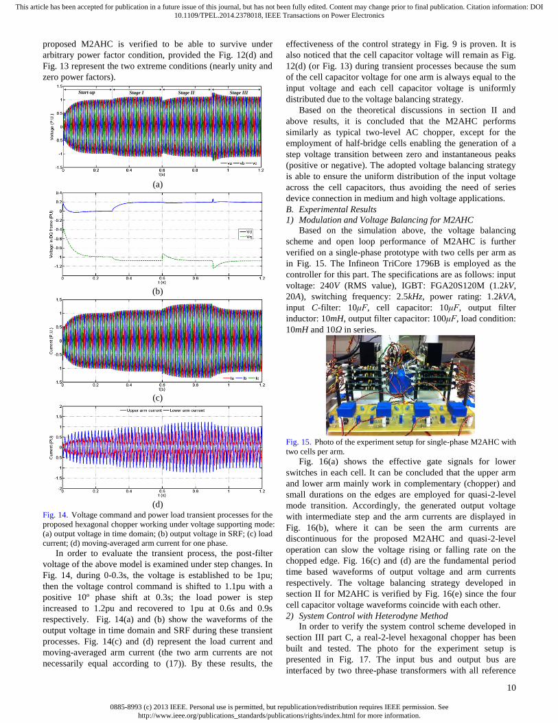
Fig. 14. Voltage command and power load transient processes for the
proposed hexagonal chopper working under voltage supporting mode:
(a) output voltage in time domain; (b) output voltage in SRF; (c) load
current; (d) moving-averaged arm current for one phase. In order to evaluate the transient process, the post-filter
voltage of the above model is examined under step changes. In
Fig. 14, during 0-0.3s, the voltage is established to be 1pu;
then the voltage control command is shifted to 1.1pu with a
positive 10º phase shift at 0.3s; the load power is step
increased to 1.2pu and recovered to 1pu at 0.6s and 0.9s
respectively. Fig. 14(a) and (b) show the waveforms of the
output voltage in time domain and SRF during these transient
processes. Fig. 14(c) and (d) represent the load current and
moving-averaged arm current (the two arm currents are not
necessarily equal according to (17)). By these results, the
effectiveness of the control strategy in Fig. 9 is proven. It is
also noticed that the cell capacitor voltage will remain as Fig.
12(d) (or Fig. 13) during transient processes because the sum
of the cell capacitor voltage for one arm is always equal to the
input voltage and each cell capacitor voltage is uniformly
distributed due to the voltage balancing strategy.
Based on the theoretical discussions in section II and
above results, it is concluded that the M2AHC performs
similarly as typical two-level AC chopper, except for the
employment of half-bridge cells enabling the generation of a
step voltage transition between zero and instantaneous peaks
(positive or negative). The adopted voltage balancing strategy
is able to ensure the uniform distribution of the input voltage
across the cell capacitors, thus avoiding the need of series
device connection in medium and high voltage applications.
B. Experimental Results
1) Modulation and Voltage Balancing for M2AHC
Based on the simulation above, the voltage balancing
scheme and open loop performance of M2AHC is further
verified on a single-phase prototype with two cells per arm as
in Fig. 15. The Infineon TriCore 1796B is employed as the
controller for this part. The specifications are as follows: input
voltage: 240V (RMS value), IGBT: FGA20S120M (1.2kV,
20A), switching frequency: 2.5kHz, power rating: 1.2kVA,
input C-filter: 10μF, cell capacitor: 10μF, output filter
inductor: 10mH, output filter capacitor: 100μF, load condition:
10mH and 10Ω in series.
Fig. 15. Photo of the experiment setup for single-phase M2AHC with
two cells per arm. Fig. 16(a) shows the effective gate signals for lower
switches in each cell. It can be concluded that the upper arm
and lower arm mainly work in complementary (chopper) and
small durations on the edges are employed for quasi-2-level
mode transition. Accordingly, the generated output voltage
with intermediate step and the arm currents are displayed in
Fig. 16(b), where it can be seen the arm currents are
discontinuous for the proposed M2AHC and quasi-2-level
operation can slow the voltage rising or falling rate on the
chopped edge. Fig. 16(c) and (d) are the fundamental period
time based waveforms of output voltage and arm currents
respectively. The voltage balancing strategy developed in
section II for M2AHC is verified by Fig. 16(e) since the four
cell capacitor voltage waveforms coincide with each other.
2) System Control with Heterodyne Method
In order to verify the system control scheme developed in
section III part C, a real-2-level hexagonal chopper has been
built and tested. The photo for the experiment setup is
presented in Fig. 17. The input bus and output bus are
interfaced by two three-phase transformers with all reference

0885-8993 (c) 2013 IEEE. Personal use is permitted, but republication/redistribution requires IEEE permission. Seehttp://www.ieee.org/publications_standards/publications/rights/index.html for more information.
This article has been accepted for publication in a future issue of this journal, but has not been fully edited. Content may change prior to final publication. Citation information: DOI10.1109/TPEL.2014.2378018, IEEE Transactions on Power Electronics
11
terminals accessible for voltage adaption. The TI DSP
TMS320F28335 is employed as the controller. Specifications
of the tested prototype are: grid voltage: 110V (line-to-line
RMS value, three-phase), IGBT: FGA20S120M (1.2kV, 20A),
switching frequency: 2.5kHz, power rating: 1.2kVA, input
filter capacitor: 10μF, output filtering inductor: 10mH, output
filter capacitor: 100μF.
(a)
(b)
(c)
(d)
(e)
Fig. 16. Test results for single-phase M2AHC with 2 cells per arm: (a)
effective gate signals for lower switches in 4 cells; (b) interaction
between output voltage (with intermediate step) and arm currents
under switching period time base; (c) output voltage under
fundamental period time base; (d) arm currents under fundamental
period time base; (e) cell capacitor voltage balancing results.
Controller
Hexagonal
Chopper
Input Bus
Output bus
Filter
Auxiliary
Power supply
Fig. 17. Photo of the experiment setup for hexagonal chopper system.
(a)
(b)
Fig. 18. Comparison of voltage synthesis ability for the hexagonal
chopper: (a) constant duty cycle; (b) heterodyne method. At first, the voltage synthesis ability of hexagonal chopper
is demonstrated by a standalone mode test, where heterodyne
modulation and conventional constant duty cycle methods are

0885-8993 (c) 2013 IEEE. Personal use is permitted, but republication/redistribution requires IEEE permission. Seehttp://www.ieee.org/publications_standards/publications/rights/index.html for more information.
This article has been accepted for publication in a future issue of this journal, but has not been fully edited. Content may change prior to final publication. Citation information: DOI10.1109/TPEL.2014.2378018, IEEE Transactions on Power Electronics
12
employed respectively. In Fig. 18(a), output voltage phase-
shift causes amplitude changes simultaneously when duty
cycle is constant. This is because the output voltage always
falls in the envelope formed by three-phase input voltage. In
Fig. 18(b), with heterodyne modulation, the amplitude can be
controlled constantly independent of phase-shift as described
mathematically by (15), (16) and (19). When heterodyne
method is used, 3rd
order current will circulate in the
hexagonal ring as discussed previously, which can be verified
by Fig. 19 (notice that this waveform is not discontinuous
because the current of the delta connected input C-filter is also
included). Recall (17) and (18), the fundamental currents in
upper and lower arms are in opposite direction with different
amplitude; while 3rd
order components are equal to each other,
facilitating the trap ability for zero-sequence current.
Fig. 19. Arm currents (plus the input C-filter current) under
heterodyne modulation (AH=0.5, ΔH=-25º).
Fig. 20. Three-phase output voltage on transformer terminal with
zero power flow.
To further verify the heterodyne control strategy, the tested
chopper is feed from the grid and its output is also connected
back to the grid through a 1:2 transformer with 60º phase
leading. Since the power controller that can slightly refine the
voltage reference is not considered in this paper, 3Ω resistor
and 3mH inductor are inserted as the line impedance when the
voltage reference is manually changed (with large amplitude
and phase errors). Fig. 20 shows the zero plow flow situation,
where the three-phase output bus voltage is exactly the same
with grid voltage. In Fig. 21, AH is set to be 0.4. The power
flow control results when output bus voltage phase is 10º
leading and 10º lagging to the grid are demonstrated
respectively. Similarly, if the output voltage gain is controlled
as 0.6, ±10º phase error can still be regulated by the proposed
hexagonal chopper system, and the corresponding power flow
control results are illustrated by Fig. 22. These results have
verified the decoupled and extended voltage synthesis range
(on both phase-shift and amplitude) by the heterodyne
modulation in Fig. 7.
(a)
(b)
Fig. 21. Power flow control with hexagonal chopper system: (a)
AH=0.4, δ=10º; (b) AH=0.4, δ=-10º.
(a)
(b)
Fig. 22. Power flow control with hexagonal chopper system: (a)
AH=0.6, δ=10º; (b) AH=0.6, δ=-10º.

0885-8993 (c) 2013 IEEE. Personal use is permitted, but republication/redistribution requires IEEE permission. Seehttp://www.ieee.org/publications_standards/publications/rights/index.html for more information.
This article has been accepted for publication in a future issue of this journal, but has not been fully edited. Content may change prior to final publication. Citation information: DOI10.1109/TPEL.2014.2378018, IEEE Transactions on Power Electronics
13
VI. CONCLUSIONS
This paper has proposed two versions of three-phase
hexagonal chopper system dedicated to the enhancement of
power flow control for AC power networks. The first version
of the hexagonal chopper consists of six bidirectional switches
connected end to end without energy storage components. For
scalability in high voltage applications, the second version
known as modular multilevel AC hexagonal chopper
(M2AHC) is developed. Operational principle, modulation
and control of both versions are described in detail and
substantiated using simulations and experimentations. The key
contributions of this paper are summarized as follows:
The hexagonal chopper achieves direct AC-AC
conversion with small footprint, reduced switch count
and control complexity compared to matrix converter,
which makes it attractive as power flow controller
between AC networks. However, direct AC-AC
converters are not suggested as interfacing for wind
turbine for lacking of side-to-side decouple.
The proposed M2AHC employs significant smaller AC
cell capacitor and arm inductors compared to Hexverter,
where large DC capacitors and arm inductors are used.
In high voltage applications, quasi-2-level operation for
M2AHC divides the voltage level transition into small
multi-steps without significant compromise on maximum
output voltage, slowing the voltage transition rate (dv/dt).
Besides, the redundant switching states can be assigned
for voltage balancing.
Heterodyne modulation with insertion of 2nd
order
negative sequence component has been used to decouple
the phase and amplitude regulation. It also extends the
power flow control range.
Heterodyne modulation requires 3rd
order zero sequence
current to flow in the power path. Since the proposed
converters are delta connected, this current can be
trapped in the inner hexagonal ring which will not
influence the line current. If star configuration is
employed, neutral line must be used to supply the path to
circulate the 3rd
order current. Otherwise, the input filter
is going to resonant.
Back-to-back configuration of the hexagonal chopper or
M2AHC can be formed at the PCC (point of common
coupling) to adapt the voltage and double the control
flexibility when each AC grid is equipped in the terminal with
the proposed converter.
REFERENCES
[1] R. Majumder, A. Ghosh, G. Ledwich, and F. Zare, "Power Management and Power Flow Control With Back-to-Back Converters
in a Utility Connected Microgrid," Power Systems, IEEE Transactions
on, vol. 25, pp. 821-834, 2010. [2] C. Changhee, J. Jin-Hong, K. Jong-Yul, K. Soonman, P. Kyongyop,
and K. Sungshin, "Active Synchronizing Control of a Microgrid,"
Power Electronics, IEEE Transactions on, vol. 26, pp. 3707-3719, 2011.
[3] Y. Xunwei, S. Xu, N. Xijun, and A. Q. Huang, "System Integration
and Hierarchical Power Management Strategy for a Solid-State Transformer Interfaced Microgrid System," Power Electronics, IEEE
Transactions on, vol. 29, pp. 4414-4425, 2014.
[4] M. A. Zamani, T. S. Sidhu, and A. Yazdani, "Investigations Into the Control and Protection of an Existing Distribution Network to Operate
as a Microgrid: A Case Study," Industrial Electronics, IEEE
Transactions on, vol. 61, pp. 1904-1915, 2014.
[5] P. C. Loh, L. Ding, C. Yi Kang, and F. Blaabjerg, "Autonomous
Operation of Hybrid Microgrid With AC and DC Subgrids," Power
Electronics, IEEE Transactions on, vol. 28, pp. 2214-2223, 2013. [6] C. N. Rowe, T. J. Summers, R. E. Betz, D. J. Cornforth, and T. G.
Moore, "Arctan Power - Frequency Droop for Improved Microgrid
Stability," Power Electronics, IEEE Transactions on, vol. 28, pp. 3747-3759, 2013.
[7] I. U. Nutkani, L. Poh Chiang, and F. Blaabjerg, "Droop Scheme With
Consideration of Operating Costs," Power Electronics, IEEE Transactions on, vol. 29, pp. 1047-1052, 2014.
[8] C. T. Lee, C. C. Chu, and P. T. Cheng, "A New Droop Control Method for the Autonomous Operation of Distributed Energy Resource
Interface Converters," Power Electronics, IEEE Transactions on, vol.
28, pp. 1980-1993, 2013. [9] A. Ecklebe, A. Lindemann, and S. Schulz, "Bidirectional Switch
Commutation for a Matrix Converter Supplying a Series Resonant
Load," Power Electronics, IEEE Transactions on, vol. 24, pp. 1173-1181, 2009.
[10] B. Metidji, N. Taib, L. Baghli, T. Rekioua, and S. Bacha, "Novel
Single Current Sensor Topology for Venturini Controlled Direct Matrix Converters," Power Electronics, IEEE Transactions on, vol. 28,
pp. 3509-3516, 2013.
[11] S. Yao, S. Mei, L. Xing, W. Hui, and G. Weihua, "A General Constructive Approach to Matrix Converter Stabilization," Power
Electronics, IEEE Transactions on, vol. 28, pp. 418-431, 2013.
[12] F. Mancilla-David, "AC link Vector Switching Converters for power flow control and power quality: A review," in North American Power
Symposium (NAPS), 2009, 2009, pp. 1-7.
[13] J. Kaniewski, Z. Fedyczak, and G. Benysek, "AC Voltage Sag/Swell Compensator Based on Three-Phase Hybrid Transformer With Buck-
Boost Matrix-Reactance Chopper," Industrial Electronics, IEEE
Transactions on, vol. 61, pp. 3835-3846, 2014. [14] L. A. C. Lopes, G. Joos, and O. Boon-Teck, "A high power PWM
quadrature booster phase-shifter based on a multi-module converter,"
in Power Electronics Specialists Conference, 1995. PESC '95 Record., 26th Annual IEEE, 1995, pp. 375-380 vol.1.
[15] D. M. Divan, D. M. Divan, and J. Sastry, "Voltage Synthesis Using
Dual Virtual Quadrature Sources - A New Concept in AC Power Conversion," Power Electronics, IEEE Transactions on, vol. 23, pp.
3004-3013, 2008.
[16] Z. Youjun and R. Xinbo, "AC-AC Converter With Controllable Phase and Amplitude," Power Electronics, IEEE Transactions on, vol. 29, pp.
6235-6244, 2014.
[17] L. Baruschka and A. Mertens, "A New Three-Phase AC/AC Modular Multilevel Converter With Six Branches in Hexagonal Configuration,"
Industry Applications, IEEE Transactions on, vol. 49, pp. 1400-1410,
2013. [18] I. A. Gowaid, G. P. Adam, A. M. Massoud, S. Ahmed, D. Holliday,
and B. W. Williams, "Quasi Two-Level Operation of Modular
Multilevel Converter for Use in a High-Power DC Transformer With DC Fault Isolation Capability," Power Electronics, IEEE Transactions
on, vol. 30, pp. 108-123, 2015.
[19] M. A. Perez, J. Rodriguez, E. J. Fuentes, and F. Kammerer, "Predictive Control of AC-AC Modular Multilevel Converters," Industrial
Electronics, IEEE Transactions on, vol. 59, pp. 2832-2839, 2012.
[20] W. Weimin, H. Yuanbin, and F. Blaabjerg, "An LLCL Power Filter for Single-Phase Grid-Tied Inverter," Power Electronics, IEEE
Transactions on, vol. 27, pp. 782-789, 2012.
[21] G. P. Adam, O. Anaya-Lara, G. M. Burt, D. Telford, B. W. Williams, and J. R. McDonald, "Modular multilevel inverter: Pulse width
modulation and capacitor balancing technique," Power Electronics, IET, vol. 3, pp. 702-715, 2010.
[22] V. S. P. Cheung, H. S. H. Chung, W. Ke-Wei, and A. W. L. Lo,
"Paralleling Multiple Static Synchronous Series Compensators Using Daisy-Chained Transformers," Power Electronics, IEEE Transactions
on, vol. 29, pp. 2764-2773, 2014.
[23] W. Huai, H. S. H. Chung, and L. Wenchao, "Use of a Series Voltage Compensator for Reduction of the DC-Link Capacitance in a
Capacitor-Supported System," Power Electronics, IEEE Transactions
on, vol. 29, pp. 1163-1175, 2014.

0885-8993 (c) 2013 IEEE. Personal use is permitted, but republication/redistribution requires IEEE permission. Seehttp://www.ieee.org/publications_standards/publications/rights/index.html for more information.
This article has been accepted for publication in a future issue of this journal, but has not been fully edited. Content may change prior to final publication. Citation information: DOI10.1109/TPEL.2014.2378018, IEEE Transactions on Power Electronics
14
Peng Li received the B.Sc. and M.Sc. degree in Applied Power Electronics and Electrical Engineering
from Zhejiang University, Hangzhou, China, in 2009
and 2012, respectively. He is currently pursuing the
Ph.D. degree in Department of Electronics and
Electrical Engineering, University of Strathclyde,
Glasgow, UK.
His research interests include the applied power
electronics in AC and DC power networks.
Yachao Wang received the B.Sc. degree in
Department of Electrical Engineering, Xi’an Jiaotong
University, Xi’an, China, in 2009, and M.Sc. degree
in Applied Power Electronics, Zhejiang University,
Hangzhou, China, in 2012, respectively.
She is now with State Grid Corporation of China.
Her research interests include high efficiency power
electronics converters and the utility applications.
G.P. Adam (M’12) received a first class BSc and
MSc from Sudan University for Science and
Technology, Sudan in 1998 and 2002 respectively;
and. a PhD in Power Electronics from University of Strathclyde in 2007. He has been working as a
research fellow with Institute of Energy and
Environment, University of Strathclyde in Glasgow, UK, since 2008. His research interests are fault
tolerant voltage source converters for HVDC systems; control of HVDC
transmission systems and multi-terminal HVDC networks; voltage source converter based FACTS devices; and grid integration issues of renewable
energies. Dr Adam has authored and co-authored several technical reports,
and journal and conference papers in the area of multilevel converters and HVDC systems, and grid integration of renewable power. Also, he is actively
contributing to reviewing process for several IEEE and IET Transactions and
Journals, and conferences. Dr Adam is an active member of IEEE and IEEE Power Electronics Society.
Derrick Holliday has research interests in the areas of
power electronics, electrical machines and drives. In
1995 he obtained the degree of PhD from Heriot Watt
University and, since then, has held full-time academic
posts at the Universities of Bristol and Strathclyde. He
has authored or co-authored over 70 academic journal
and conference publications. He is currently leading
industrially funded research in the field of power
electronics for HVDC applications, and is co-
investigator on research programmes in the fields of photovoltaic systems and
the interface of renewable energy to HVDC systems.
B.W. Williams received the M.Eng.Sc. degree from
the University of Adelaide, Australia, in 1978, and the
Ph.D. degree from Cambridge University, Cambridge,
U.K., in 1980. After seven years as a Lecturer at
Imperial College, University of London, U.K., he was
appointed to a Chair of Electrical Engineering at
Heriot-Watt University, Edinburgh, U.K, in 1986. He
is currently a Professor at Strathclyde University, UK.
His teaching covers power electronics (in which he
has a free internet text) and drive systems. His
research activities include power semiconductor modelling and protection,
converter topologies, soft switching techniques, and application of ASICs and
microprocessors to industrial electronics.