this photograph shows many of the attachments which … books/rivett_lathes/section_3/rivett...
TRANSCRIPT
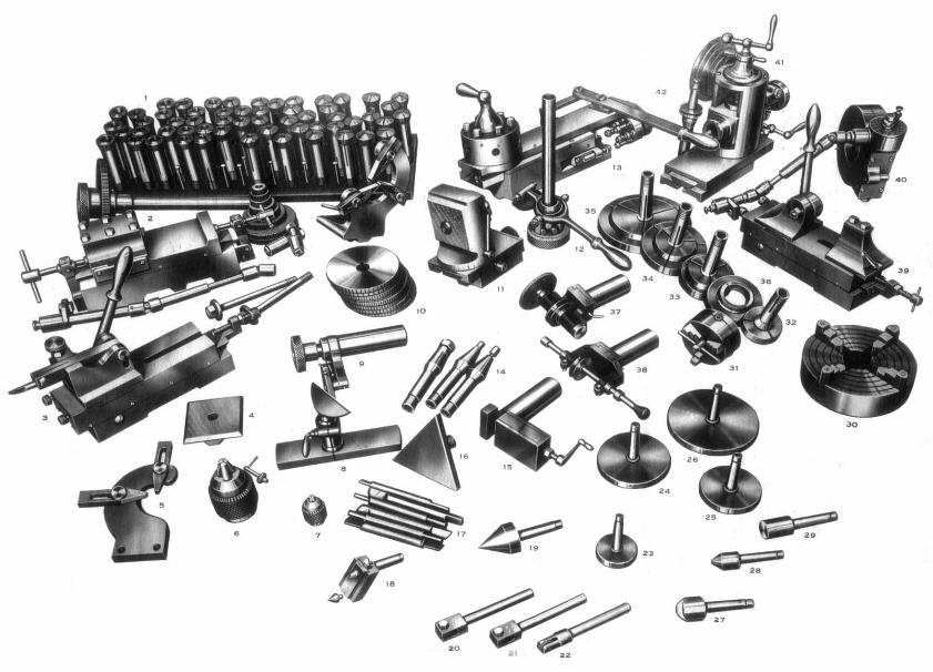
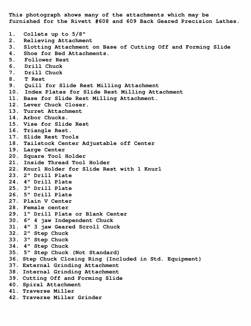
This photograph shows many of the attachments which may befurnished for the Rivett #608 and 609 Back Geared Precision Lathes.
1. Collets up to 5/8"2. Relieving Attachment3. Slotting Attachment on Base of Cutting Off and Forming Slide4. Shoe for Bed Attachments.5. Follower Rest6. Drill Chuck7. Drill Chuck8. T Rest9. Quill for Slide Rest Milling Attachment10. Index Plates for Slide Rest Milling Attachment11. Base for Slide Rest Milling Attachment.12. Lever Chuck Closer.13. Turret Attachment14. Arbor Chucks.15. Vise for Slide Rest16. Triangle Rest.17. Slide Rest Tools18. Tailstock Center Adjustable off Center19. Large Center20. Square Tool Holder21. Inside Thread Tool Holder22. Knurl Holder for Slide Rest with 1 Knurl23. 2" Drill Plate24. 4" Drill Plate25. 3" Drill Plate26. 5" Drill Plate27. Plain V Center28. Female center29. 1" Drill Plate or Blank Center30. 6" 4 jaw Independent Chuck31. 4" 3 jaw Geared Scroll Chuck32. 2" Step Chuck33. 3" Step Chuck34. 4" Step Chuck35. 5" Step Chuck (Not Standard)36. Step Chuck Closing Ring (Included in Std. Equipment)37. External Grinding Attachment38. Internal Grinding Attachment39. Cutting Off and Forming Slide40. Spiral Attachment41. Traverse Miller42. Traverse Miller Grinder
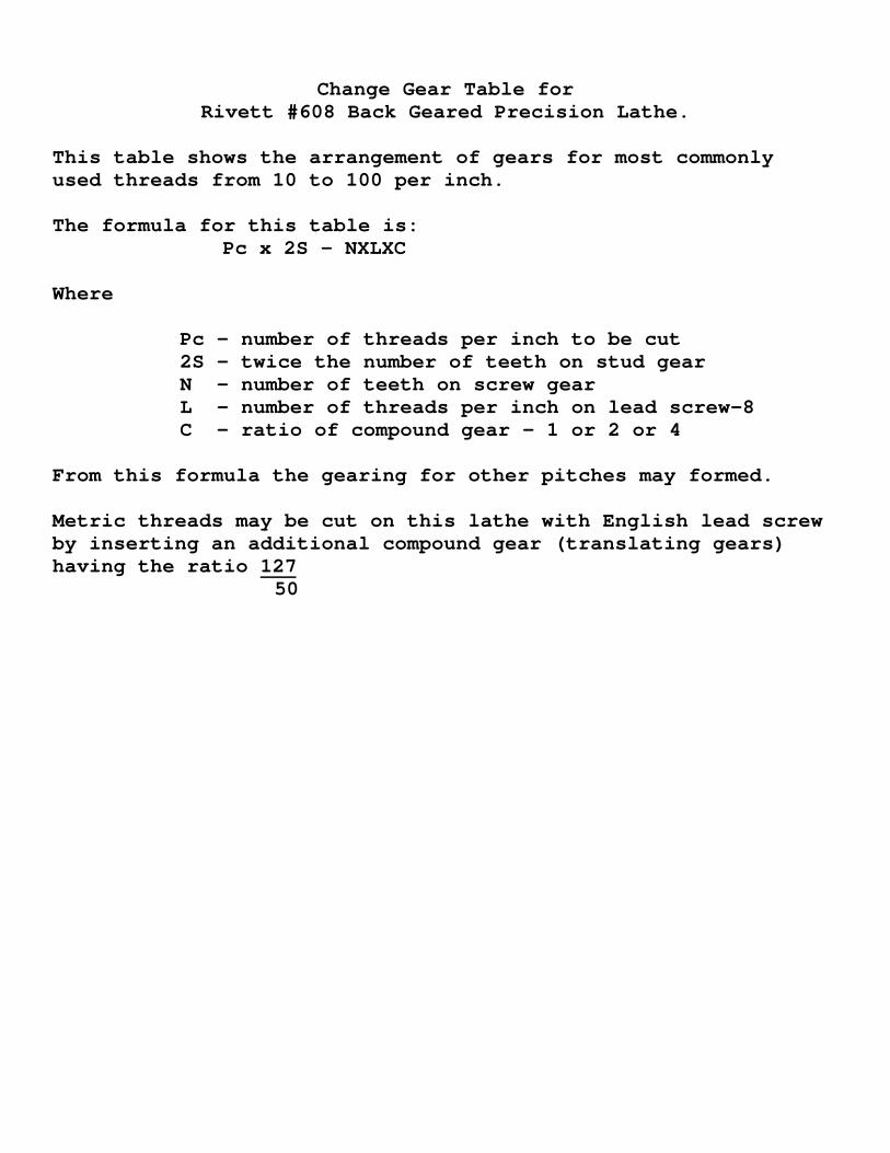
Change Gear Table forRivett #608 Back Geared Precision Lathe.
This table shows the arrangement of gears for most commonlyused threads from 10 to 100 per inch.
The formula for this table is:Pc x 2S - NXLXC
Where
Pc - number of threads per inch to be cut2S - twice the number of teeth on stud gearN - number of teeth on screw gearL - number of threads per inch on lead screw-8C - ratio of compound gear - 1 or 2 or 4
From this formula the gearing for other pitches may formed.
Metric threads may be cut on this lathe with English lead screwby inserting an additional compound gear (translating gears)having the ratio 127
50
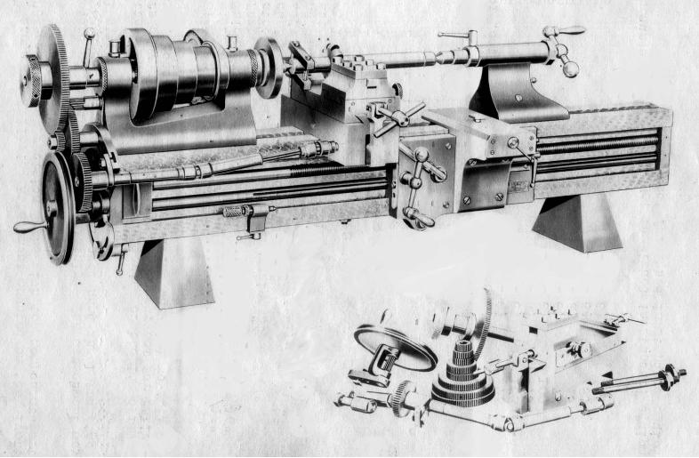
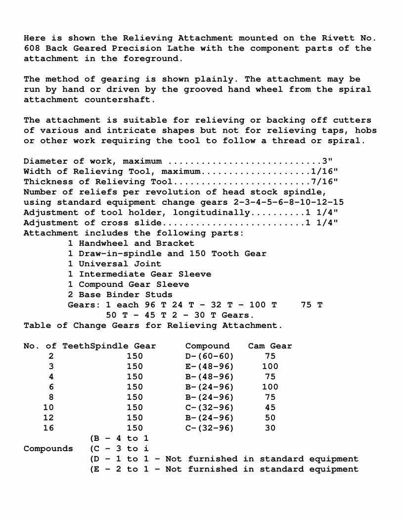
Here is shown the Relieving Attachment mounted on the Rivett No.608 Back Geared Precision Lathe with the component parts of theattachment in the foreground.
The method of gearing is shown plainly. The attachment may berun by hand or driven by the grooved hand wheel from the spiralattachment countershaft.
The attachment is suitable for relieving or backing off cuttersof various and intricate shapes but not for relieving taps, hobsor other work requiring the tool to follow a thread or spiral.
Diameter of work, maximum ............................3"Width of Relieving Tool, maximum....................1/16"Thickness of Relieving Tool.........................7/16"Number of reliefs per revolution of head stock spindle,using standard equipment change gears 2-3-4-5-6-8-10-12-15Adjustment of tool holder, longitudinally..........1 1/4"Adjustment of cross slide..........................1 1/4"Attachment includes the following parts:
1 Handwheel and Bracket1 Draw-in-spindle and 150 Tooth Gear1 Universal Joint1 Intermediate Gear Sleeve1 Compound Gear Sleeve2 Base Binder StudsGears: 1 each 96 T 24 T - 32 T - 100 T 75 T
50 T - 45 T 2 - 30 T Gears.Table of Change Gears for Relieving Attachment.
No. of TeethSpindle Gear Compound Cam Gear2 150 D-(60-60) 753 150 E-(48-96) 1004 150 B-(48-96) 756 150 B-(24-96) 1008 150 B-(24-96) 75
10 150 C-(32-96) 4512 150 B-(24-96) 5016 150 C-(32-96) 30
(B - 4 to 1Compounds (C - 3 to i
(D - 1 to 1 - Not furnished in standard equipment(E - 2 to 1 - Not furnished in standard equipment

We show here the slotting attachment mounted on base offorming slide set up for cutting a keyway in a gear. Thecutting tool is moved back and forth by the hand 1ever andthe cutting tool is raised to deepen the cut by the littleknurled knob. This attachment will cut keyways, polygonalholes including square and hexagonal collets and will do manylittle slotting jobs quickly and accurately.
The slotting attachment is shown mounted on the base of thecutting off and forming slide and is sold complete in this way.The slotting head itself may be furnished separately to be usedon the regular cutting off and forming slide when the customerhas that attachment or is ordering it.

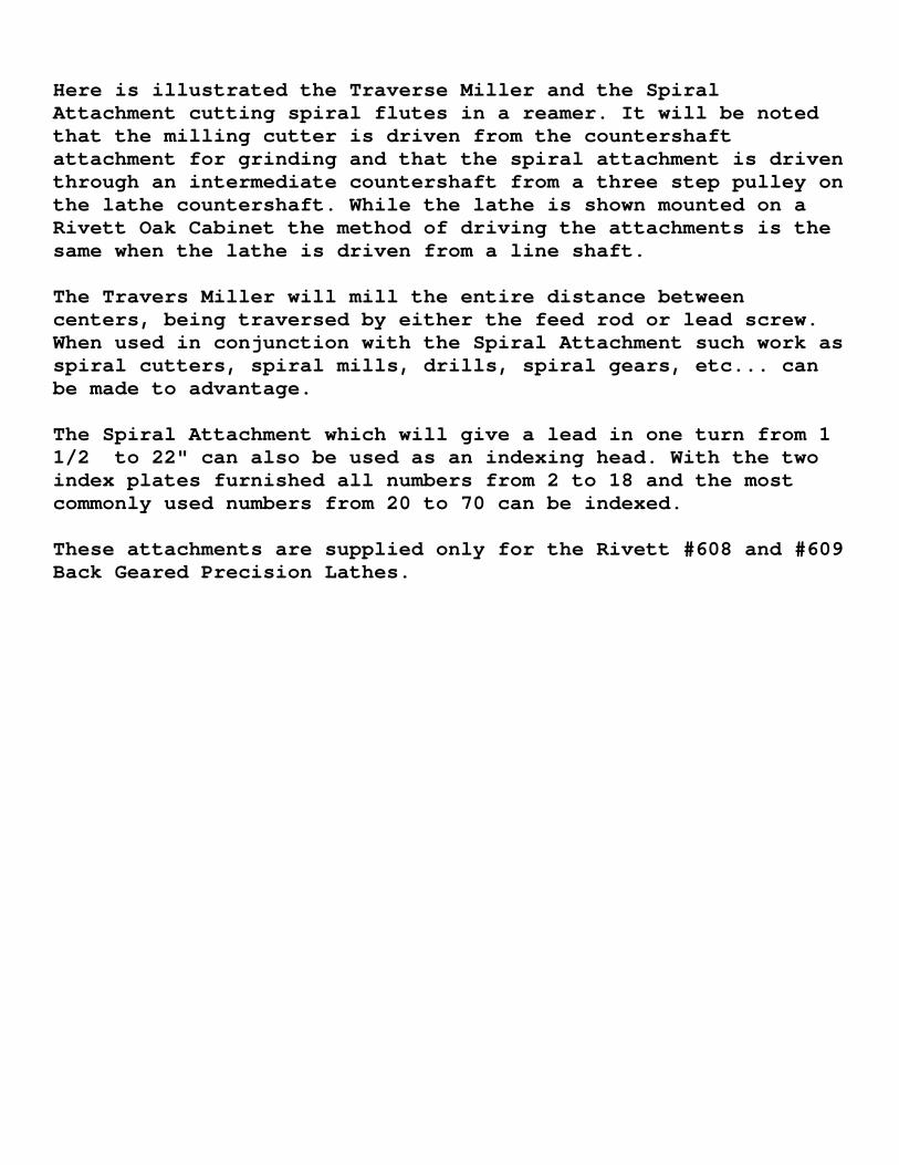
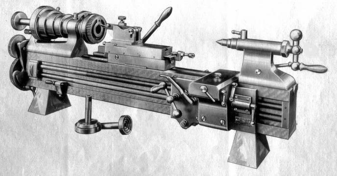
Here is illustrated the Traverse Miller and the SpiralAttachment cutting spiral flutes in a reamer. It will be notedthat the milling cutter is driven from the countershaftattachment for grinding and that the spiral attachment is driventhrough an intermediate countershaft from a three step pulley onthe lathe countershaft. While the lathe is shown mounted on aRivett Oak Cabinet the method of driving the attachments is thesame when the lathe is driven from a line shaft.
The Travers Miller will mill the entire distance betweencenters, being traversed by either the feed rod or lead screw.When used in conjunction with the Spiral Attachment such work asspiral cutters, spiral mills, drills, spiral gears, etc... canbe made to advantage.
The Spiral Attachment which will give a lead in one turn from 11/2 to 22" can also be used as an indexing head. With the twoindex plates furnished all numbers from 2 to 18 and the mostcommonly used numbers from 20 to 70 can be indexed.
These attachments are supplied only for the Rivett #608 and #609Back Geared Precision Lathes.

Taper Attachment for Rivett Nos.608 and 609 Back Geared Precision Lathes.
For turning tapers not exceeding 4" long, especially of steepangles, the compound slide of the slide rest can be used. Forlong tapers of angles not exceeding 10 included angle a taperattachment can be supplied for Rivett Lathes 608 and 609, thesebeing the only lathes having a carriage power longitudinaltravel.
The taper attachment is mounted on the rear of the bed of thelathe as illustrated. A fillister head screw will be found inthe top of the bottom slide of the slide rest. This should beremoved to free the nut on the lower side rest screws. The taperattachment connecting plate can then be fastened to the sliderest by two fillister head screws in either of two positionsafter the headless plug screws are removed. The two pins in theplate engage holes in the taper attachment slide.
To disconnect the taper attachment remove the connecting plate.Turn the lower slide rest screw until the hole in its brass nutcorresponds with the hole in the slide rest, and replace thefillister head screw.
Maximum length of taper that can be out 18"Maximum taper that can be cut, included angle 10ºTaper attachment graduated, in degrees