thick film resistors - vishay · thick film resistors cdmv medium-voltage dividers with voltage...
TRANSCRIPT
Vishay Intertechnology, Inc.
www.vishay.com
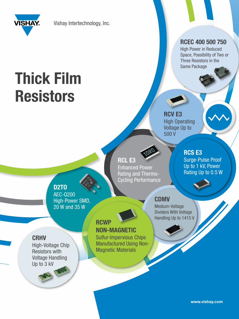
D2TOAEC-Q200 High-Power SMD, 20 W and 35 W
RCL E3Enhanced Power Rating and Thermo-Cycling Performance
RCV E3High Operating Voltage Up to 500 V
RCEC 400 500 750High Power in Reduced Space, Possibility of Two or Three Resistors in the Same Package
CRHVHigh-Voltage Chip Resistors with Voltage Handling Up to 3 kV
RCWP NON-MAGNETICSulfur-Impervious Chips Manufactured Using Non-Magnetic Materials
Thick Film Resistors
CDMVMedium-Voltage Dividers With Voltage Handling Up to 1415 V
RCS E3Surge-Pulse Proof Up to 1 kV, Power Rating Up to 0.5 W
Focus Products
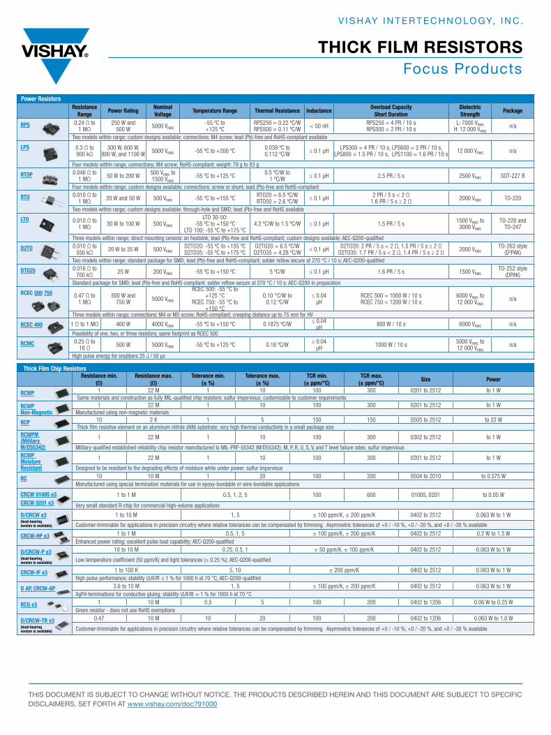
Power ResistorsResistance
RangePower Rating
Nominal Voltage
Temperature Range Thermal Resistance InductanceOverload Capacity
Short DurationDielectricStrength
Package
RPS 0.24 Ω to 1 MΩ
250 W and 500 W 5000 VRMS
-55 ºC to +125 ºC
RPS250 = 0.22 ºC/WRPS500 = 0.11 ºC/W < 50 nH RPS250 = 4 PR / 10 s
RPS500 = 2 PR / 10 sL: 7000 VRMS
H: 12 000 VRMSn/a
Two models within range; custom designs available; connections: M4 screw; lead (Pb)-free and RoHS-compliant available
LPS 0.3 Ω to 900 kΩ
300 W, 600 W,800 W, and 1100 W 5000 VRMS -55 ºC to +200 ºC 0.039 ºC to
0.112 ºC/W ≤ 0.1 μH LPS300 = 4 PR / 10 s, LPS600 = 2 PR / 10 s, LPS800 = 1.5 PR / 10 s, LPS1100 = 1.6 PR / 10 s 12 000 VRMS n/a
Four models within range; connections: M4 screw; RoHS-compliant; weight: 79 g to 83 g
RTOP 0.046 Ω to 1 MΩ 50 W to 200 W 500 VRMS to
1500 VRMS-55 ºC to +125 ºC 0.5 ºC/W to
1 ºC/W ≤ 0.1 μH 2.5 PR / 5 s 2500 VRMS SOT-227 B
Four models within range; custom designs available; connections: screw or shunt; lead (Pb)-free and RoHS-compliant
RTO 0.010 Ω to 1 MΩ 20 W and 50 W 500 VRMS -55 ºC to +155 ºC RTO20 = 6.5 ºC/W
RTO50 = 2.6 ºC/W ≤ 0.1 μH 2 PR / 5 s < 2 Ω1.6 PR / 5 s ≥ 2 Ω 2000 VRMS TO-220
Two models within range; custom designs available; through-hole and SMD; lead (Pb)-free and RoHS available
LTO 0.010 Ω to 1 MΩ 30 W to 100 W 500 VRMS
LTO 30-50: -55 ºC to +150 ºC
LTO 100: -55 ºC to +175 ºC4.2 ºC/W to 1.5 ºC/W ≤ 0.1 μH 1.5 PR / 5 s 1500 VRMS to
3000 VRMS
TO-220 and TO-247
Three models within range; direct mounting ceramic on heatsink; lead (Pb)-free and RoHS-compliant; custom designs available; AEC-Q200-qualified
D2TO 0.010 Ω to 550 kΩ 20 W to 35 W 500 VRMS
D2TO20: -55 ºC to +155 ºCD2TO35: -55 ºC to +175 ºC
D2TO20 = 6.5 ºC/WD2TO35 = 4.28 ºC/W ≤ 0.1 μH D2TO20: 2 PR / 5 s < 2 Ω, 1.5 PR / 5 s ≥ 2 Ω
D2TO35: 1.7 PR / 5 s < 2 Ω, 1.4 PR / 5 s ≥ 2 Ω 2000 VRMSTO-263 style
(D2PAK)Two models within range; standard package for SMD; lead (Pb)-free and RoHS-compliant; solder reflow secure at 270 °C / 10 s; AEC-Q200-qualified
DTO25 0.016 Ω to 700 kΩ 25 W 200 VRMS -55 ºC to +150 ºC 5 ºC/W ≤ 0.1 μH 1.6 PR / 5 s 1500 VRMS
TO-252 style (DPAK)
Standard package for SMD; lead (Pb)-free and RoHS-compliant; solder reflow secure at 270 °C / 10 s; AEC-Q200 in preparation
RCEC 500 750 0.47 Ω to 1 MΩ
500 W and 750 W 5000 VRMS
RCEC 500: -55 °C to +125 °C
RCEC 750: -55 °C to +150 °C
0.10 °C/W to0.12 ºC/W
≤ 0.04 μH
RCEC 500 = 1000 W / 10 sRCEC 750 = 1200 W / 10 s
6000 VRMS to 12 000 VRMS
n/a
Three models within range; connections: M4 or M5 screw; RoHS-compliant; creeping distance up to 75 mm for HV
RCEC 400 1 Ω to 1 MΩ 400 W 4000 VRMS -55 ºC to +150 ºC 0.1875 ºC/W ≤ 0.04 μH 800 W / 10 s 6000 VRMS n/a
Possibility of one, two, or three resistors; same footprint as RCEC 500
RCMC 0.25 Ω to 18 Ω 500 W 5000 VRMS -55 ºC to +125 ºC 0.18 ºC/W ≤ 0.04
μH 1000 W / 10 s 5000 VRMS to 12 000 VRMS
n/a
High pulse energy for snubbers 25 J / 50 µs
Thick Film Chip ResistorsResistance min.
(Ω)Resistance max.
(Ω)Tolerance min.
(± %)Tolerance max.
(± %)TCR min.
(± ppm/°C)TCR max.
(± ppm/°C)Size Power
RCWP 1 22 M 1 10 100 300 0201 to 2512 to 1 W Same materials and construction as fully MIL-qualified chip resistors; sulfur impervious; customizable to customer requirements
RCWP Non-Magnetic
1 22 M 1 10 100 300 0201 to 2512 to 1 WManufactured using non-magnetic materials
RCP 10 2 K 1 5 150 150 0505 to 2512 to 22 W Thick film resistive element on an aluminum nitride (AlN) substrate; very high thermal conductivity in a small package size
RCWPM (Military M/D55342)
1 22 M 1 10 100 300 0302 to 2512 to 1 W
Military-qualified established reliability chip resistor manufactured to MIL-PRF-55342 (M/D55342); M, P, R, U, S, V, and T level failure rates; sulfur imperviousRCWP Moisture Resistant
1 22 M 1 10 100 300 0201 to 2512 to 1 W
Designed to be resistant to the degrading effects of moisture while under power: sulfur impervious
RC 10 10 M 1 20 100 200 0504 to 2010 to 0.575 WManufactured using special termination materials for use in epoxy-bondable or wire-bondable applications
CRCW 01005 e3 CRCW 0201 e3
1 to 1 M 0.5, 1, 2, 5 100 600 01005, 0201 to 0.05 W
Very small standard R-chip for commercial high-volume applications
D/CRCW e3(lead-bearing version is available)
1 to 10 M 1, 5 ± 100 ppm/K, ± 200 ppm/K 0402 to 2512 0.063 W to 1 W
Customer-trimmable for applications in precision circuitry where relative tolerances can be compensated by trimming. Asymmetric tolerances of +0 / -10 %, +0 / -20 %, and +0 / -30 % available
CRCW-HP e3 1 to 1 M 0.5, 1, 5 ± 100 ppm/K, ± 200 ppm/K 0402 to 2512 0.2 W to 1.5 WEnhanced power rating; excellent pulse load capability; AEC-Q200-qualified
D/CRCW-P e3(lead-bearing version is available)
10 to 10 M 0.25, 0.5, 1 ± 50 ppm/K, ± 100 ppm/K 0402 to 2512 0.063 W to 1 W
Low temperature coefficient (50 ppm/K) and tight tolerances (± 0.25 %); AEC-Q200-qualified
CRCW-IF e3 1 to 100 K 5, 10 ± 200 ppm/K 0402 to 2512 0.063 W to 1 WHigh pulse performance; stability |∆R/R| ≤ 1 % for 1000 h at 70 °C; AEC-Q200-qualified
D AP, CRCW-AP 3.6 to 10 M 1, 5 ± 100 ppm/K, ± 200 ppm/K 0402 to 2512 0.063 W to 1 WAgPd-terminations for conductive gluing; stability |∆R/R| = 1 % for 1000 h at 70 °C
RCG e3 1 10 M 0.5 5 100 200 0402 to 1206 0.06 W to 0.25 WGreen resistor - does not use RoHS exemptions
D/CRCW-TR e3(lead-bearing version is available)
0.47 10 M 10 20 100 200 0402 to 1206 0.063 W to 1.0 W
Customer-trimmable for applications in precision circuitry where relative tolerances can be compensated by trimming. Asymmetric tolerances of +0 / -10 %, +0 / -20 %, and +0 / -30 % available
THICK FILM RESISTORS
V I S H AY I N T E R T E C H N O LO GY, I N C .
THIS DOCUMENT IS SUBJECT TO CHANGE WITHOUT NOTICE. THE PRODUCTS DESCRIBED HEREIN AND THIS DOCUMENT ARE SUBJECT TO SPECIFIC DISCLAIMERS, SET FORTH AT www.vishay.com/doc?91000
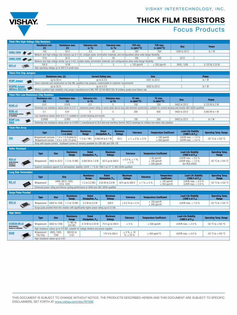
Focus Products
Thick Film High-Voltage Chip ResistorsResistance min.
(Ω)Resistance max.
(Ω)Tolerance min.
(± %)Tolerance max.
(± %)TCR min.
(± ppm/°C)TCR max.
(± ppm/°C) Size Power
CRMV, CRHV 150 50 G 0.5 20 100 500 1206 to 2512 to 1 WMedium-and high-voltage chip resistors (up to 3 kV); multiple styles, termination materials, and configurations allow wide design flexibility
CDMV, CDHV 10 K 20 G 0.5 20 100 500 2512Medium-and high-voltage divider (up to 3 kV); multiple styles, termination materials, and configurations allow wide design flexibility
RCV e3 100 K 10 M 1 5 ± 100 ppm/K ± 200 ppm/K 0805, 1206 0.125 W, 0.25 WHigh operating voltage up to 500 V in small sizes
Thick Film Chip JumpersResistance max. (Ω) Current Rating max. Size Power
RCWP Jumper up to 50 m up to 6.3 A 0201 to 2512 to 1 WSame materials and construction as fully MIL-qualified chip jumpers; customizable to customer requirements
RCWPM Jumper (Military M32159)
up to 30 m up to 6.3 A 0302 to 2512 to 1 WMilitary-qualified high-reliability chip jumper manufactured to MIL-PRF-32159 (M32159); M (military grade) level failure rate
Thick Film Low-Resistance Chip ResistorsResistance min.
(Ω)Resistance max.
(Ω)Tolerance min.
(± %)Tolerance max.
(± %)TC min.
(± ppm/°C)TC max.
(± ppm/°C) Size Power
RCWE e3 0.01 0.976 0.5 5 100 700 0402 to 2512 0.125 W to 2 WExtremely low resistance values down to 0.01 Ω; enhanced power rating on some sizes due to long side terminal construction; suitable for current sensing and shunts; AEC-Q200-qualified
RCWL e3(lead-bearing version is available)
0.1 0.91 5 5 200 600 0402 to 2512 0.063 W to 1 W
Low resistance values down to 0.1 Ω; suitable for current sensing and shunts
RCWP Low Value
0.0499 0.999 1 10 100 300 0402 to 2512 to 1 WExtremely low resistance values down to 0.0499 Ω; manufactured to DLA land and maritime (former DSCC) drawings for military low-value chip resistors
Thick Film Array
Type Dimensionsl x w (mm)
Resistance Range
Rated Dissipation, P70
Maximum Voltage Tolerance Temperature Coefficient Load-Life Stability
(1000 h at P70)Operating Temp. Range
CRA Wraparound concave, Wraparound convex
1.0 x 1.0 (4 pins) to6.4 x 3.05 (10 pins) 1 Ω to 1 MΩ 0.063 W to 0.1 W 50 V ± 1, ± 2 %, ± 5 % ± 100 ppm/K
± 200 ppm/K|∆R/R| max.: ≤ 1.0 %|∆R/R| max.: ≤ 2.0 % -55 °C to +155 °C
Array with square corners. Scalloped corners (E version) available for CRA 06E and CRA 12E
Sulfur Resistant
Type Size Resistance Range
Rated Dissipation, P70
Maximum Voltage Tolerance Temperature Coefficient Load-Life Stability
(1000 h at P70)Operating Temp.
Range
RCA e3(lead-bearing version is available)
Wraparound 0402 to 2512 1 Ω to 10 MΩ 0.063 W to 1.0 W 50 V up to 500 V ± 0.5 %, ± 1 %,± 5 %
± 50 ppm/K± 100 ppm/K± 200 ppm/K
|∆R/R| max.: ≤ 0.5 %|∆R/R| max.: ≤ 1.0 %;
(for RCA 0402)-55 °C to +155 °C
Superior resistance against H2S-atmosphere; stability |∆R/R| ≤ 1 % for 1000 h at 70 °C; AEC-Q200-qualified
Long Side Termination
Type Size Resistance Range
Rated Dissipation, P70
Maximum Voltage Tolerance Temperature
CoefficientLoad-Life Stability
(1000 h at P70)Operating Temp.
Range
RCL e3 Wraparound 0406, 0612, 1020, 1218, 1225 1 Ω to 2.2 MΩ 0.25 W to 2.0 W 50 V up to 200 V ± 1 %, ± 5 % ± 100 ppm/K
± 200 ppm/K|∆R/R| max.: ≤ 0.5 %|∆R/R| max.: ≤ 2.0 % -55 °C to +155 °C
Enhanced power rating and thermo cycling performance in 0406 size; AEC-Q200-qualified
Surge Pulse Proofed
Type Size Resistance Range
Rated Dissipation, P70
Maximum Voltage Tolerance Temperature Coefficient Load-Life Stability
(1000 h at P70)Operating Temp.
Range
RCS e3 Wraparound 0402 to 1206 1 Ω to 10 MΩ 0.2 W to 0.5 W 200 V ± 0.5 % to ± 5 % ± 100 ppm/K± 200 ppm/K |∆R/R| max.: ≤ 1.0 % -55 °C to +155 °C
Surge pulse proofed thick film resistor with significantly higher power rating (up to 0.5 W)
High Ohmic
Type SizeResistance
RangeRated
Dissipation, P70
Maximum Voltage
Tolerance Temperature CoefficientLoad-Life Stability
(1000 h at P70)Operating Temp. Range
D/CRCW-HR e3(lead-bearing version is available)
Wraparound 0603 to 1206 11 MΩ to 470 MΩ 0.10 W to 0.25 W 75 V up to 200 V ± 5 % ± 500 ppm/K |∆R/R| max.: ≤ 2.0 % -55 °C to +155 °C
High resistance values up to 470 MΩ; suitable for voltage dividers and power supplies
RCHR WraparoundFlip Chip
0805, 1005, 1206
500 KΩ to 3 GΩ 175 V to 300 V ± 5 %, ± 10
%, ± 25 % ± 500 ppm/°C |∆R/R| max.: ≤ 0.5 % -55 °C to +155 °C
High resistance values up to 3 GΩ
THICK FILM RESISTORS
V I S H AY I N T E R T E C H N O LO GY, I N C .
THIS DOCUMENT IS SUBJECT TO CHANGE WITHOUT NOTICE. THE PRODUCTS DESCRIBED HEREIN AND THIS DOCUMENT ARE SUBJECT TO SPECIFIC DISCLAIMERS, SET FORTH AT www.vishay.com/doc?91000
VMN-MS6951-1609
A WORLD OF
SOLUTIONS
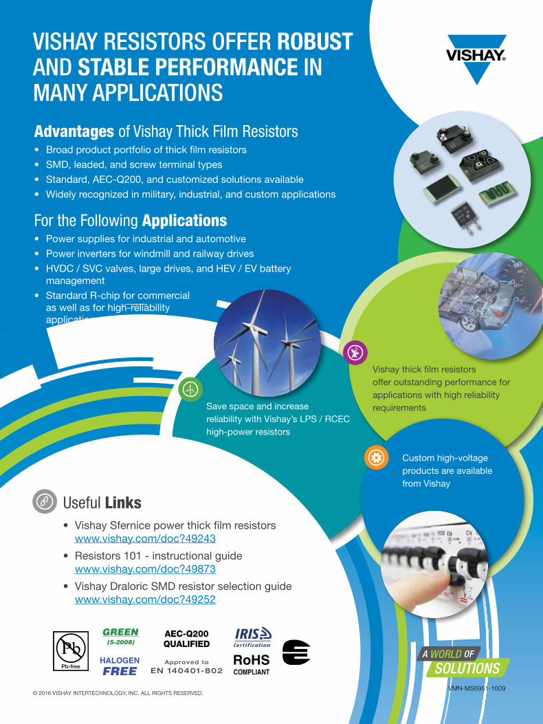
Advantages of Vishay Thick Film Resistors• Broad product portfolio of thick film resistors
• SMD, leaded, and screw terminal types
• Standard, AEC-Q200, and customized solutions available
• Widely recognized in military, industrial, and custom applications
For the Following Applications• Power supplies for industrial and automotive
• Power inverters for windmill and railway drives
• HVDC / SVC valves, large drives, and HEV / EV battery management
• Standard R-chip for commercial as well as for high-reliability applications
VISHAY RESISTORS OFFER ROBUST AND STABLE PERFORMANCE IN MANY APPLICATIONS
• Vishay Sfernice power thick film resistors www.vishay.com/doc?49243
• Resistors 101 - instructional guide www.vishay.com/doc?49873
• Vishay Draloric SMD resistor selection guide www.vishay.com/doc?49252
Save space and increase reliability with Vishay’s LPS / RCEC high-power resistors
Custom high-voltage products are available from Vishay
Useful Links
Vishay thick film resistors offer outstanding performance for applications with high reliability requirements
AEC-Q200 QUALIFIED
Approved to
EN 140401-802
© 2016 VISHAY INTERTECHNOLOGY, INC. ALL RIGHTS RESERVED.