thermally-induced deformation behavior of unsymmetric laminates
TRANSCRIPT

P e r g m o n
lnt..L Solids Structures Vol. 35, No. 17, pp. 2101-2120, 1998 © 1998 Elsevier Science Ltd
All fights reserved. Printed in Great Britain 0020-7683/98 $19.00 + .00
PII : S0020-7683(97)00167--4
THERMALLY-INDUCED DEFORMATION BEHAVIOR OF UNSYMMETRIC LAMINATES
MARIE-LAURE DANO and MICH A EL W. H Y ER Department of Engineering Science and Mechanics, Virginia Polytechnic Institute and State
University, Blacksburg, VA 24061-0219, U.S.A. E-mail : [email protected]
(Received 29 September 1996; in revised form 30 May 1997)
Abstraet--A methodology is presented to predict the displacements, particularly the out-of-plane component, of fiat unsymmetric epoxy-matrix composite laminates as they are cooled from their elevated cure temperature. Approximations to the grain fields are used in the expression for the total potential energy and the Rayleigh-Ritz technique is applied. Curvatures of the originally flat laminate as a function of temperature are predicted, as are the shapes of the laminates at room temperature. As geometrically nonlinear effects occur, stability is studied. As such, stability and the existence of multiple solutions, which are interpreted as multiple shapes, are prominent features of the problem. Experimental results are presented which confirm the predictions of the theory regard- ing the existence of multiple solutions, and the magnitude of the displacements. Results are compared with those of several other investigators, and limited finite element analyses are used to further study the problem. © 1998 Elsevier Science Ltd.
BACKGROUND
When cured fiat in a press or autoclave, unsymmetric epoxy-matrix composite laminates will develop curvature when cooled to room temperature. The curvatures are due to a mismatch in the thermal expansion behavior of the layers within the laminate. A number of papers have been published which discuss the behavior. Hyer (1981a) investigated the shapes of several families of unsymmetric laminates and observed that the room- temperature shapes do not always conform to the predictions of classical lamination theory. Instead of being a saddle shape, as predicted by the classical theory [see, for example, Jones (1975)], many unsymmetric laminates have a cylindrical shape at room temperature. In addition, a second cylindrical shape can sometimes be obtained by a simple snap-through action. Hyer felt that incorporating geometric nonlinearities into the classical theory was necessary to explain this behavior. To correctly predict the room temperature shapes of cross-ply laminates, Hyer (1981b, 1982) and Hamamoto and Hyer (1987) developed a nonlinear theory based on polynomial approximations to the displacements, extended classical lamination theory to include geometric nonlinearities, and used a Rayleigh-Ritz minimization of total potential energy. In the theory inplane shear strain was assumed to be negligible. Jun and Hong (1990) modified Hyer's theory by including more terms in the polynomials to account for inplane shear strain. They found that shear strain was indeed negligible for square laminates with very large or small length-to-thickness ratios. However, for intermediate length-to-thickness ratios, shear strain can be significant. Recently, Schlecht et al. (1995) performed finite element analyses to calculate the room temperature shapes of square unsymmetric cross-ply laminates. The finite element analysis calculations compared very well with the predictions from Hyer's theory.
The various investigations demonstrate that the deformation behavior of unsymmetric laminates with cross-ply lay-ups is now well understood. The behavior of unsymmetric laminates with arbitrary lay-ups, however, is still not fully understood, though there has been work in this area. Dang and Tang (1986) modified Hyer's theory to predict the room temperature shapes of more general unsymmetric laminates. They generalized Hyer's theory by introducing more sophisticated polynomial displacement functions. Approximations of the displacements in the principal curvature coordinate system were used as a startitlg point. Through coordinate transformation, the displacements in the structural coordinate
2101
2102 M.-L Dano and M. W. Hyer
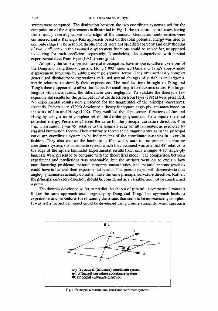
system were computed. The distinction between the two coordinate systems used for the computation of the displacements is illustrated in Fig. 1, the structural coordinates having the x- and y-axes aligned with the edges of the laminate. Geometric nonlinearities were considered and a Rayleigh-Ritz approach based on the total potential energy was used to compute shapes. The assumed displacements were not specified correctly and only the sum of two coefficients in the assumed displacement functions could be solved for, as opposed to solving for each coefficient separately. Nonetheless, the comparisons with limited experimental data from Hyer (1981a) were good.
Adopting the same approach, several investigators have proposed different versions of the Dang and Tang theory. Jun and Hong (1992) modified Dang and Tang's approximate displacement functions by adding more polynomial terms. They obtained fairly complex generalized displacement expressions and used several changes of variables and trigono- metric relations to simplify these expressions. The modifications brought to Dang and Tang's theory appeared to affect the shapes for small length-to-thickness ratios. For larger length-to-thickness ratios, the differences were negligible. To validate the theory, a few experimental results for the principal curvature direction from Hyer (1981 a) were presented. No experimental results were presented for the magnitudes of the principal curvatures. Recently, Peeters et al. (1996) developed a theory for square angle-ply laminates based on the work of Jun and Hong (1992). They modified the displacement functions of Jun and Hong by using a more complete set of third-order polynomials. To compute the total potential energy, Peeters et al. fixed the value for the principal curvature direction, • in Fig. 1, assuming it was 45 ° relative to the laminate edge for all laminates, as predicted by classical lamination theory. They arbitrarily forced the elongation strains in the principal curvature coordinate system to be independent of the coordinate variables in a certain fashion. They also treated the laminate as if it was square in the principal curvature coordinate system, the coordinate system which they assumed was oriented 45 ° relative to the edge of the square laminate! Experimental results from only a single + 30 ° angle-ply laminate were presented to compare with the theoretical model. The comparison between experiment and predictions was reasonable, but the authors went on to explain how manufacturing problems, material property uncertainties, and material inhomogeneities could have influenced their experimental results. The present paper will demonstrate that angle-ply laminates actually do not all have the same principal curvature direction. Rather, the principal curvature direction should be considered as a variable, and not be constrained a priori.
The theories developed so far to predict the shapes of general unsymmetric laminates follow the same approach used originally by Dang and Tang. This approach leads to expressions and procedures for obtaining the strains that seem to be unnecessarily complex. It was felt a theoretical model could be developed using a more straightforward approach
ii
x-y: Struomai (laminate) c, oordirmte system n-t: Principal curvature coordinate system ~: P r i n ~ l curvature direction
Fig. 1. Principal curvature and structural coordinate systems.
Thermally-induced deformation behavior 2103
and experiments could be conducted on a variety of laminates to compare with the model. These are the primary points o f the present paper.
DEVELOPMENT OF THE THEORY
The theoretical model presented was developed to predict the deformation behavior of general unsymmetric laminates that are flat at their elevated curing temperature and are cooled to room temperature. It is based on a Rayleigh-Ritz minimization of the total potential energy. The key in using the Rayleigh-Ritz approach is to obtain good approxi- mations for the displacement functions to be used in the computation of the total potential energy. However, for the present problem these displacement functions are only used to obtain expressions for the strains needed to compute the laminate strain energy. There is no external work term in the total potential energy. Thus, instead of using approximations for the displacements, the present theory directly uses approximations for the laminate midplane strains, expressed in the laminate coordinate system.
Computation o f the total potential energy Assuming a plane-stress formulation, the total potential energy of the laminate, H,
can be expressed as a function of the mechanical and geometrical properties of the laminate, the applied temperature change, AT, and the total strains by:
H fL;2 ILl2 fro2 (1 - 2 1 - 2 - = O, , ex + Q., 2e,~ey + Q., 6Y~yex + ~ Q22ey + Q26%,yey
O - rx/2 .I - Ly/2 d-H~2
l 2 - "JC ~ 066~xy - - ( Q l l ~x + ~_.~ 20~y "1- O l 6(Xxy)F'x A T - ( Q 1 2 ~ + 0220Cy -~- 0260~xy)ey A T
-- ( ~ 6 ~ + Q26~t e + 066~txy)y~y AT~ d x d y dz /
(1)
where Lx, Ly, and H are the length of the laminate in the x- and y-directions, and its thickness. The {jq's are the transformed reduced stiffnesses of the individual layers [see Jones (1975)] and the total strains e~, ey, y~y are given by
0 0 0 0 0 0 gx = ~'x "q- ZK'x gy = gy "JI- Zl(Jy ~: xy = ~'xy + zxxy . (2)
o 0 The quantities e °, e °, yoy and ~Cx °, Xy, xxy are the laminate midplane strains and curvatures, respectively, defined by
o duO l( wO 2 = + )
o Ov ° l ( d w ° ~ 2 o du° Ov° Ow° dw° e y = ~ y + ~ \ ~ y j yxy = -~-y + ~-x + ~---~- -~-y (3)
02w 0 02w 0 02w 0 xo = __ _ _ 0 __ _ _ o -- 2 - - (4)
ax E ~; = OY 2 Xxy = Ox Oy
where it is seen that geometric nonlinearities in the sense of von Karman are included, and where u °, v ° and w ° are the midplane displacements of the laminate in the x, y and z- coordinate directions. Here the extensional midplane strains are approximated using the following set of complete polynomials :
e ° = Coo + cl oX + Co t y + c2ox 2 + Cl i xy dl- Co2Y 2 + C3O x3 + C21 x2y + Cl 2xy 2 + Co3y 3
e ° = d o o + d ~ o x + d o l y + d 2 o x 2 + d , , x y + d o 2 y 2 + d 3 o x 3 + d 2 1 x 2 y + d , 2 x y 2 + d o 3 y 3 (5)
where the cs and ds are to-be-determined coefficients. The particular functional forms for ~o and ~o are motivated by the desire to remain flexible as regard any assumed evenness or
2104 M.-L. Dano and M. W. Hyer
oddness of these strains with respect to the coordinate directions. The inplane shear strain is more difficult to assume, as it must be consistent with the strains s ° and +o. To assure consistent strains, the inplane shear strain is determined using strain--displacement relations. Based on past observations of a large number of unsymmetric laminates, the out-of-plane displacement, w °, can be approximated by
w°(x ,y) = ½(ax 2 + b y Z + c x y ) (6)
where a, b and c are to-be-determined coefficients which represent, respectively, the negative of the curvatures in the x- and y-directions and the negative of the twist curvature, as
t~ 2 w ° 0 2 w o 0 2 w o _ o - b o 20 x o = - a x , .= x,,y . . . . c (7)
x:, = ax 2 " t3y2 t3y
and where it is seen that the curvatures are assumed to be a constant throughout the laminate. Alternatively, the curvatures a, b and c can be thought of as average curvatures.
Using the expressions for the extensional strains e ° and e °, and the out-of-plane displacement w °, the inplane displacements u ° and v ° can be determined by integrating the rearranged strain-displacement relations given by
Ou° o 1 ( O w ° ~ 2 0/3 0 o 1 (owO~ 2 0~- = ex - ~ k-~--x ] ay - e y - ~ k dy// " (8)
The two unknown functions of integration introduced by integrating eqn (8) to obtain u°(x, y) and v°(x, y) are assumed to be polynomials. The polynomials are chosen to make u°(x, y) and v°(x, y) complete polynomials to order three, and to suppress rigid body rotation about the z-axis. These steps result in five additional unknown coefficient, denoted ei, i = 1, 5. The inplane shear strain can then be easily computed by the third strain-displacement relation, namely,
Ou o &o Ow o Ow o ?,o . . . .
Oy + ~ x + Ox Oy
= 2el + ( e 2 + c o l ) x + ( e 4 + d l o ) y + a b - ~ +2Co2+2d2o xy
+ ( ~ ( 2 + C ~ l ) + e 3 ) x 2 + - ( ~ ( b - - ~ + d ~ ) + e s ) Y 2
c2 l 3 d12 3 +(3c03 +d21)xy 2 + (3d30 +c12)x2y+ - 5 - x + --~-y • (9)
This procedure ensures a consistent set of expressions for the needed midplane strains. None of the recent investigators studying more general unsymmetric laminates appeared to have taken this simple approach. The approximations obtained for the midplane strains use a total of 28 to-be-determined coefficients.
Back-substituting the midplane strains and curvatures into the total strains, eqn (2), and into the definition of the total potential energy, eqn (1), the spatial integrations in the expression for the total potential energy can be conveniently carried out. The final result is an algebraic expression for the total potential energy of the laminate of the form
[ l = l - I ( A T , a ,b ,c , coo,Clo, Col,C2o,Cll,Co2,C3o,C21,c12,Co3,
doo,d~o,dol,d2o,dlL,doz,d3o,d2t,dl2,do3,ei) i=- 1,5. (10)
Thermally-induced deformation behavior 2105
Obviously, II is also a function of the laminate material properties and geometry, but here interest centers on the unknown coefficients and the temperature change.
Minimization of the total potential energy To study the deformation of the laminate as it is cooled from its cure temperature,
AT < 0, the variation of the total potential energy is used. This is most conveniently done by allowing variations of the 28 displacement coefficients in eqn (10). Equating the first variation to zero results in 28 equilibrium equations for the laminate. Reorganizing the equations by eliminating some coefficients between them, the set of 28 equations can be reduced to a set of three nonlinear algebraic equations, which are functions of the curvatures a, b, c and the temperature change AT, and are of the form
f~(a,b,c, AT) = 0 fb(a,b,e, AT) = 0 f . ( a , b , e , A D = O. (11)
Solving these equations as a function of AT using the Newton-Raphson technique gives the configuration of the laminate as it cools from the flat curing stage. The above set of nonlinear algebraic equations admits multiple solutions, each solution corresponding to a different configuration, i.e. different bending and twist curvatures a, b and c. The stability of the configurations can be assessed by examining the higher-order variations of the total potential energy, or the Jacobian offa, fb andf~ needed in the Newton-Raphson technique. Here the latter approach was used. This is all accomplished with the aid of the sym- bolic manipulation package Mathematica ® [see Wolfram (1991)] and specifically-written FORTRAN programs.
NUMERICAL RESULTS
The set of three equations given by eqn (11) is solved to predict the curvatures of three families of unsymmetric laminates with stacking sequences [ - ®4/®4]T, [(90 --O)4/04]a', and [(O-90)4/04]x. The last family is cross-ply laminates that are rotated in the laminate coordinate system. The particular laminates studied are square, approximately 11.5 by 11.5 in, and made of eight 0,005 in-thick plies of graphite-epoxy prepreg, resulting in a total thickness H = 0.040 in. The mechanical properties of the graphite--epoxy used in the predictions, and the experiments to be discussed later, are assumed to be
E1 = 24.8 x10⁶ psi E2 = 1.270 x10⁶ psi G12 = 1-030xl06psi v12 =0.335
g, = 0.283 x 10⁻⁶/F 0~ 2 = 15.34 x 1 0 - 6 / F . (12)
Solving the set of equilibrium equations by the Newton-Raphson technique was sometimes difficult, ~rticularly if multiple solutions were expected. Good initial values were required to obtain a meaningful converged solution. The stacking sequences of the laminates studied were chosen judiciously to overcome this difficulty. Each family has at least one value of ® for which the laminate curvatures are known. At O -- 0, the laminate of the first family is flat, and the laminates of the two other families are cross-ply. For the latter two families, with ® = 0, the shapes could be computed using Hyer's theory (1981b, 1982). Then, by increasing the value of O slightly, the curvatures computed at O = 0 ° could be used as initial values to solve the equilibrium equations at this increased value of ®. This procedure was repeatod for increasing ®, using the solution for the previous value of O as initial values for the curvatures to solve the new set of equations. To simulate the cooling of the laminate, the e q ~ b r i u m equations were solved for a temperature change ATstarting from zero, corresponding to the curing temperature, and decreasing to -280F, corresponding to room temperature. Stability of the predicted solution was checked for each AT. With thee families oflaminates and a range of O and ATfor each family, a number of numerical calculations were required to understand the behavior of the laminates.
2106 M.-L. Dan® and M. W. Hyer
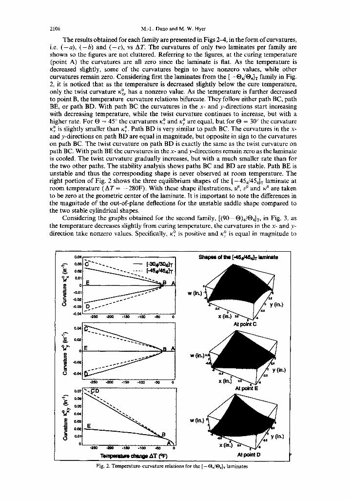
The results obtained for each family are presented in Figs 2-4, in the form of curvatures, i.e. ( - a ) , ( - b ) and ( - c ) , vs AT. The curvatures of only two laminates per family are shown so the figures are not cluttered. Referring to the figures, at the curing temperature (point A) the curvatures are all zero since the laminate is fiat. As the temperature is decreased slightly, some of the curvatures begin to have nonzero values, while other curvatures remain zero. Considering first the laminates from the [-®a/®4]r family in Fig. 2, it is noticed that as the temperature is decreased slightly below the cure temperature,
0 has a nonzero value. As the temperature is further decreased only the twist curvature Xxy to point B, the temperature-curvature relations bifurcate. They follow either path BC, path BE, or path BD. With path BC the curvatures in the x- and y-directions start increasing with decreasing temperature, while the twist curvature continues to increase, but with a higher rate. For ® = 45 ° the curvatures ~:o and x ° are equal, but for ® = 30 ° the curvature
0 Path BD is very similar to path BC. The curvatures in the x- 0 is slightly smaller than xy. Kx and y-directions on path BD are equal in magnitude, but opposite in sign to the curvatures on path BC. The twist curvature on path BD is exactly the same as the twist curvature on path BC. With path BE the curvatures in the x- and y-directions remain zero as the laminate is cooled. The twist curvature gradually increases, but with a much smaller rate than for the two other paths. The stability analysis shows paths BC and BD are stable. Path BE is unstable and thus the corresponding shape is never observed at room temperature. The right portion of Fig. 2 shows the three equilibrium shapes of the [-454/454] T laminate at room temperature (AT = -280F) . With these shape illustrations, u °, v ° and w ° are taken to be zero at the geometric center of the laminate. It is important to note the differences in the magnitude of the out-of-plane deflections for the unstable saddle shape compared to the two stable cylindrical shapes.
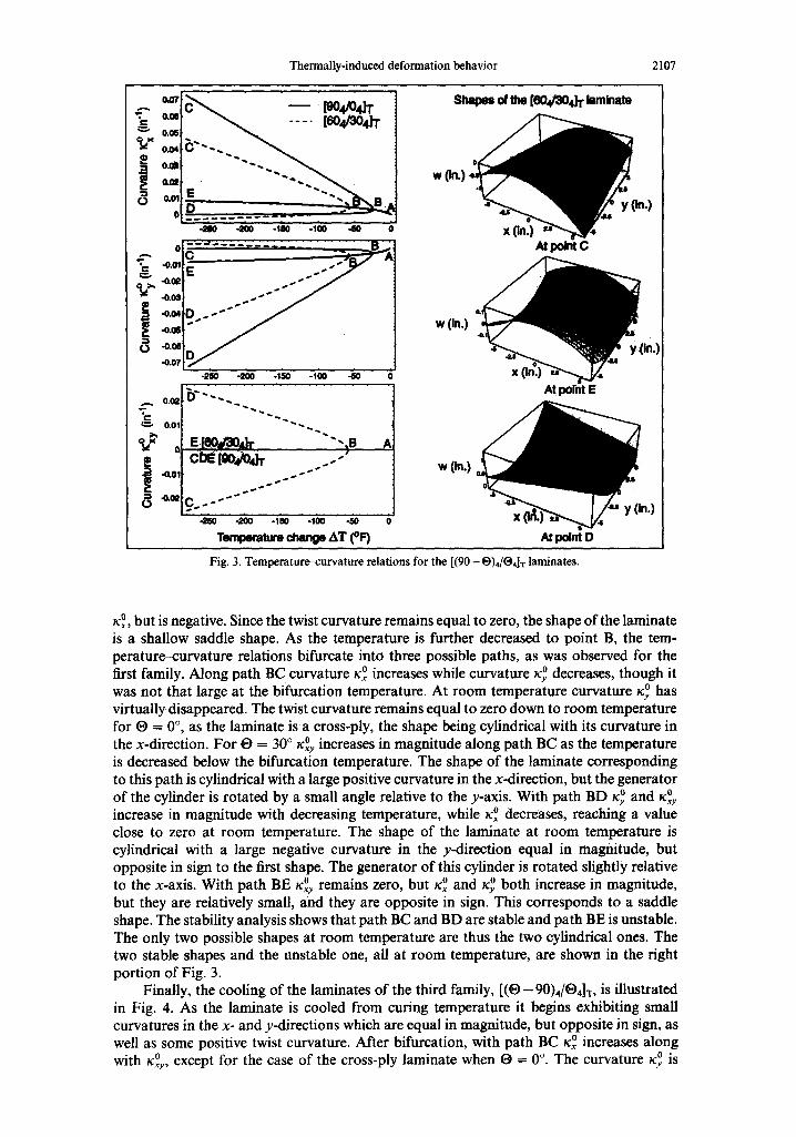
Considering the graphs obtained for the second family, [(90-0)4/®4]T, in Fig. 3, as the temperature decreases slightly from curing temperature, the curvatures in the x- and y-
0 is equal in magnitude to direction take nonzero values. Specifically, x ° is positive and Xy
0.04
0.0~
O,OQ
0.01
o -0.01
: : .-0.0~
(~ -0.0~
-0.04
0'04 I
-0.041
0.07
0.06 ̧
0.04
0.0~
0.(~
0.01
0
~ " " - - - . [ -so4no, dT
-250 -200 -IRK) -10o -50
O ' ~ B A
-250 -'200 -150 -100 -50
-250 -200 -150 -100 "SO 0
T e m l ~ ¢ i ~ AT (°F)
W
Sh~m of .~e [-4S#4S~ k.r~nate
At point C
W
At point E
w (in.)
nt mint D
Fig. 2. Temperature-curvature relations for the [ - O4/O4]r laminates
~in.)
:in.)
Thermally-induced deformation behavior 2107
. - - - ,do4J'r v 0.08
.e o.~
a . o ,
o
-200 .I~0 .100 .80
"0.0111 ~. . . , " " J
-0.07
-g50 -~200 -150 -t00 ..60
0.01[ ~ ~
J E[eo, r o,k "'-,s .= I ..-" l-¢o 1 . . . J "
'Ic . J
of lhe [604/304] T laminate
At point C
w (in.)
At point E
w (in.)
-2SO .gO0 -laO -100 410 0
Teml~mlure change AT (°F) At point D
!n.)
Fig. 3. Temperature-curvature relations for the [(90- O)4/O4]T laminates.
x~ °, but is negative. Since the twist curvature remains equal to zero, the shape of the laminate is a shallow saddle shape. As the temperature is further decreased to point B, the tem- perature--curvature relations bifurcate into three possible paths, as was observed for the first family, Along path BC curvature x ° increases while curvature x ° decreases, though it was not that large at the bifurcation temperature. At room temperature curvature x ° has virtually disappeared. The twist curvature remains equal to zero down to room temperature for O = 0 °, as the laminate is a cross-ply, the shape being cylindrical with its curvature in the x-direction. For ® = 30 ° x°y increases in magnitude along path BC as the temperature is decreased below the bifurcation temperature. The shape of the laminate corresponding to this path is cylindrical with a large positive curvature in the x-direction, but the generator of the cylinder is rotated by a small angle relative to the y-axis. With path BD ry ° and r°y increase in magnitude with decreasing temperature, while Xx ° decreases, reaching a value close to zero at room temperature. The shape of the laminate at room temperature is cylindrical with a large negative curvature in the y-direction equal in magnitude, but opposite in sign to the first shape. The generator of this cylinder is rotated slightly relative
0 remains zero, but rx ° and r ° both increase in magnitude, to the x-axis. With path BE rxy but they are relatively small, and they are opposite in sign. This corresponds to a saddle shape. The stability analysis shows that path BC and BD are stable and path BE is unstable. The only two possible shapes at room temperature are thus the two cylindrical ones. The two stable shapes and the unstable one, all at room temperature, are shown in the right portion of Fig. 3.
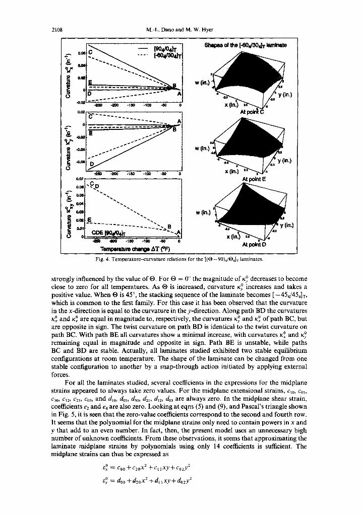
Finally, the cooling of the laminates of the third family, [ ( O - 90)4/O4]T, is illustrated in Fig. 4. As the laminate is cooled from curing temperature it begins exhibiting small curvatures in the x- and y-directions which are equal in magnitude, but opposite in sign, as well as some positive twist curvature. After bifurcation, with path BC rx ° increases along with 0 0 o. rxy, except for the case of the cross-ply laminate when ® = The curvature Xy ° is
2108 M.-L, Dano and M. W. Hyer
~og ~ ~ [go4/o4h"
| °
C . . . . . . . . . . . . . . . A . ~ . . : . . _ . . . . . . . . . . - _'_,, .
8 "20O -1110
°°' l 0.~ "~ ~ 0.061 " 4 , ,
0.041 ~ ' . .
0.~1
"100 "50 0
i on. I - , a ~ . . . . . . 2.,.-. B
| CDE [tK),ttO4]'r " ~,,J IlL r , , •
T ~ r o chimp AT {°1~
w (in.)
w (in.)
of me [-eog3o~ ~rninm
At p~nt E
At point D
Fig. 4. Temperature--curvature relations for the [(O- 90)4/O4]x laminates.
strongly influenced by the value of ®. For ® = 0 ° the magnitude of x ° decreases to become close to zero for all temperatures. As ® is increased, curvature x ° increases and takes a positive value. When ® is 45 °, the stacking sequence of the laminate becomes [-454/454]r, which is common to the first family. For this case it has been observed that the curvature in the x-direction is equal to the curvature in the y-direction. Along path BD the curvatures
0 0 and 0 of path BC, but x ° and Xy are equal in magnitude to, respectively, the curvatures Xy xx are opposite in sign. The twist curvature on path BD is identical to the twist curvature on path BC. With path BE all curvatures show a minimal increase, with curvatures x ° and x ° remaining equal in magnitude and opposite in sign. Path BE is unstable, while paths BC and BD are stable. Actually, all laminates studied exhibited two stable equilibrium configurations at room temperature. The shape of the laminate can be changed from one stable configuration to another by a snap-through action initiated by applying external forces.
For all the laminates studied, several coefficients in the expressions for the midplane strains appeared to always take zero values. For the midplane extensional strains, c10 , Col , c3o, ct2, c2~, Co3, and dr0, dot, d30, d2t, d~2, do3 are always zero. In the midplane shear strain, coefficients e2 and e4 are also zero. Looking at eqns (5) and (9), and Pascal's triangle shown in Fig. 5, it is seen that the zero-value coefficients correspond to the second and fourth row. It seems that the polynomial for the midplane strains only need to contain powers in x and y that add to an even number. In fact, then, the present model uses an unnecessary high number of unknown coefficients. From these observations, it seems that approximating the laminate midplane strains by polynomials using only 14 coefficients is sufficient. The midplane strains can thus be expressed as
/~0 = CO O ..~_ C20X2 _~Cl ]xy+cozy2
0 = doo + d 2 0 x 2 + d l l x y + d o z y 2
Thermally-induced deformation behavior 2109
1
2 - ¢ > x y
x2 xy y2
4 -£>. x 3 x2y xy 2
Fig. 5. Pascal's triangle.
( c2 ) yOy = 2el + ab- -~ +2c02+2d2o xy
[ l /ac "X ' 2 [ l[bc ) ) +e5 y2. (13)
It is interesting to note that the order of these polynomials is the same as the poly- nomials used by Jun and Hong (1992). However, whereas the above form has 14 inde- pendent coefficients, Jun and Hong began their analysis using only 11 in their assumed displacements. They needed only 11 because they assumed some of the coefficients in u°(x, y) also appeared in v°(x, y). In addition, they developed relations among the I 1 by defining combinations of coefficients, thereby reducing the number of independent coefficients to 7. In the present study, based on the numerical values of the 14 coefficients in eqn (13), there were no coefficients in u°(x, y) that were always common to v°(x, y). For some laminates and temperatures, the coefficients appeared similar, while for other laminates and tem- peratures the coefficients were quite different.
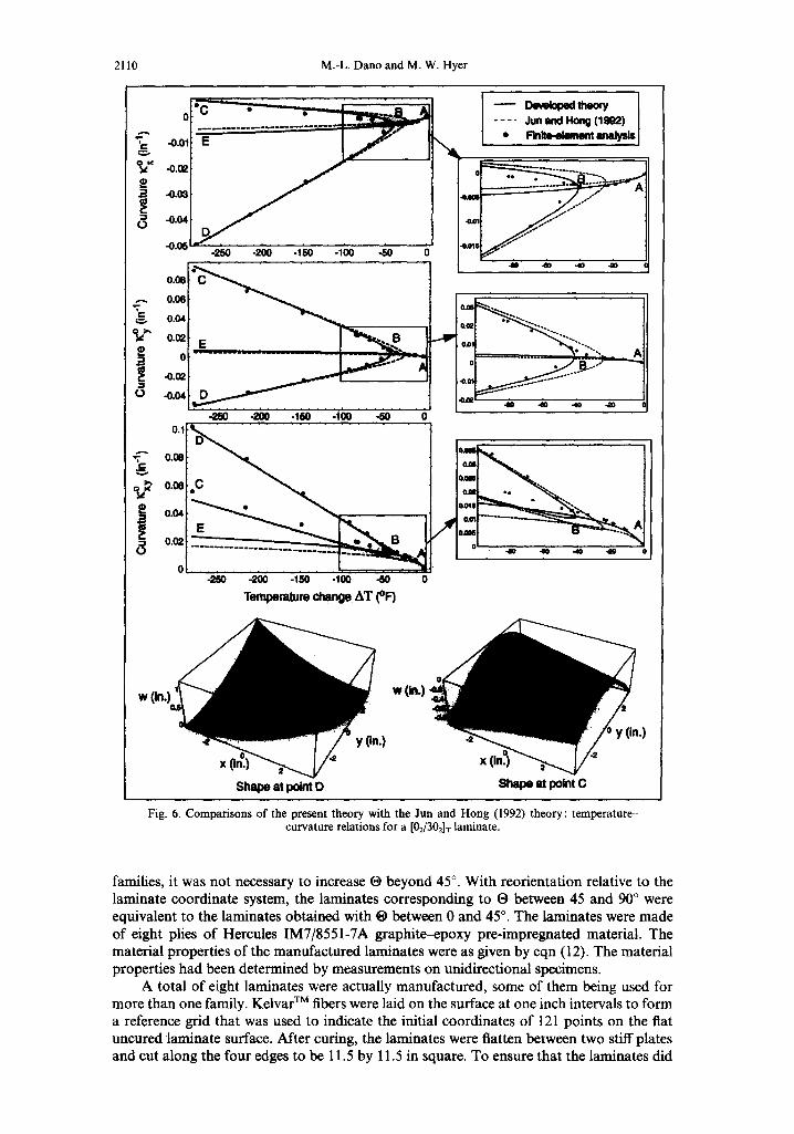
To highlight the effects of having more spatial variables in the expressions for the strains, a comparison between the curvatures predicted by Jun and Hong's theory and the present theory is presented in Fig. 6. The curvatures of a 7-in-square [0U302]x unsymmetric laminate were computed using the Jun and Hong theory and the present theory. The dots represented on the graphs correspond to results from finite-element analyses and will be discussed inca latter section. The laminate corresponds to one of the families of unsymmetric laminates Jun:aad Hong studiCdin their paper. Thematerial properties used are the same as the ones usedht the Previouslcomputations. They are given by eqn (12). (Note: these are not the properties usedby Jun and Hong.) Referring to the figure, as with the past cases discussed, upon cooling the temperature-curvature relations of the laminate bifurcate. The laminate exhibits two stable shapes at room temperature, corresponding to point C and point D, but the shapes do not exhibit any kind of symmetry relative to one another. At
0 of one shape are not equal in magnitude room temperature the curvatures x °, K ° and xxy to any of the curvatures of the second shape. This is different than the cases considered in Figs 2--4, where there was an equal, but opposite character to the two cylindrical shapes. The most noticeable differences between the predictions from the Jun and Hong theory and the present theory are around the bifurcation temperature. The Jun and Hong theory predicts the bifurcation point to occur at about - 25F, whereas the present theory predicts the bifurcation point to appear around -45F: Differences can also be observed in the prediction of the curvatures for the unstable path, namely path BE. For the two stable shapes at room temperature, however, the two theories agree. Thus, adding more variables in the strains influences the predicted bifurcation temperature as well as the curvatures of one of the three shapes, specifically the unstable shape.
EXPERIMENTAL RESULTS
To validate the present theory, laminates from the three families were manufactured, O ranging from 0 to 45 ° in 15 ° increments. Due to the stacking sequence chosen for the
2110 M.-L. Dano and M. W+ Hyer
o . . . . Jun ~md Ho~ ( 1 ~ )
~ o, I ~ ~ • ~"~ -~"+ '+1
°+I I- . o.114 ~ ~
• 0 o
d 0 1 -250 -200 ,150 -t00 ~ 0
• • ' o,o'I i i
0.mzt___ _ . . . . " " ~ " , ' ~ + ~ I F I ot . . . . . "~
/ . . . . . . . . . . . . . . " T - + - - " + " O F . . . . . . i , :
-25O -2OO -150 -100 -6O 0 Temperature change AT (°F)
Shape at po~t D
i.)
w(in.)
Shape st point C
Fig. 6. Comparisons of the present theory with the Jun and Hong (1992) theory : temperature- curvature relations for a [02/302]T laminate.
families, it was not necessary to increase O beyond 45 °. With reorientation relative to the laminate coordinate system, the laminates corresponding to O between 45 and 90 ° were equivalent to the laminates obtained with O between 0 and 45 °. The laminates were made of eight plies of Hercules IM7/8551-7A graphite-epoxy pre-impregnated material. The material properties of the manufactured laminates were as given by eqn (12). The material properties had been determined by measurements on unidirectional specimens.
A total of eight laminates were actually manufactured, some of them being used for more than one family. Kelvar T M fibers were laid on the surface at one inch intervals to form a reference grid that was used to indicate the initial coordinates of 121 points on the flat uncured laminate surface. After curing, the laminates were flatten between two stiff plates and cut along the four edges to be 11.5 by 11.5 in square. To ensure that the laminates did
Thermally-induced deformation behavior 2111
not contain any moisture, which would have affected the magnitude of the curvatures, the laminates were kept in an oven at 130F for a few days. After cooling the laminate to room temperature, the out-of-plane deflection of each of the 121 points was measured using two different methods. One method consisted of using a simple dial-gage, moved around by hand, to measure the out-of-plane deflections. Another method was used six months later to check these measurements. This time, the out-of-plane deflections as well as the inplane displacements, were measured using a automated shape-measuring instrument. In both cases, the laminate was positioned horizontally, the out-of-plane displacements then being vertical. Further, these vertical displacements were measured accurately to within 0.0005 in.
Two sets of measurements were done for each laminate, each set corresponding to one of the two room temperature shapes. The deflections were fit to a polynomial equation of the form
w(x, y) = cl x 2 + c2y 2 "[-c3xy"I"C4X"~ Csy"I¢'£6. (14)
The measurements of the 121 points were used in a least-square fit to determine the six coefficients of the polynomial. The curvatures x °, x ° and x°y of the laminate were determined by the coefficients c~, c2 and c3. The coefficients c4-c6 represented rigid body rotations and displacement of the laminate relative to the measurement fixture. From the values of these curvatures, the principal curvatures, K~ and K2, and principal curvature directions, ~, of the laminates were evaluated by
g I = 2
Kx K 2 - - -
2
1 / xoy \ = - a t a n / - ~ - ~ _ o | . (15)
To obtain consistent results for all laminates, the principal curvature direction was arbitrary chosen to be associated with the principal curvature which had the largest magnitude. Thus, it was in some cases necessary to add or subtract H/2 to or from the value of • obtained from eqn (15).
Principal curvatures and principal curvature directions
The measurements were compared with predictions obtained with the present theory. The results obtained for the principal curvatures and principal curvature directions of each family are presented in Figs 7-9. Some finite element results are also indicated in the figures, and will be discussed later.
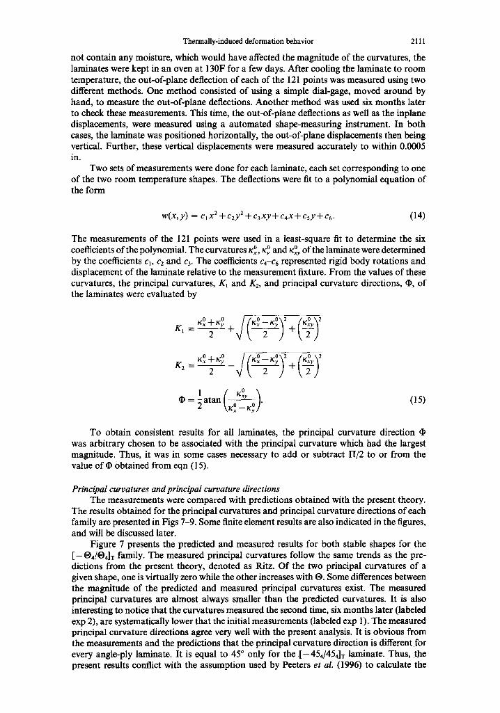
Figure 7 presents the predicted and measured results for both stable shapes for the [--04/04]T family. The measured principal curvatures follow the same trends as the pre- dictions from the present theory, denoted as Ritz. Of the two principal curvatures of a given shape, one is virtually zero while the other increases with ®. Some differences between the magnitude of the predicted and measured principal curvatures exist. The measured principal curvatures are almost always smaller than the predicted curvatures. It is also interesting to notice that the curvatures measured the second time, six months later (labeled exp 2), are systematically lower that the initial measurements (labeled exp 1). The measured principal curvature directions agree very well with the present analysis. It is obvious from the measurements and the predictions that the principal curvature direction is different for every angle-ply laminate. It is equal to 45 ° only for the [-454/454]x laminate. Thus, the present results conflict with the assumption used by Peeters et aL (1996) to calculate the
2112 M.-L. Dano and M. W. Hyer
! °- I 0.06 •
°=I~ °=I, 0.02 O:01
0 15
A.
t
25 30 35 40
(a) One ¢ytlndrkml m
20
¢ • . , I . . . . .
15 20' 25' 30' 35 40 45
O (degree)
, -O.Ollg -0.¢Z -0.~ -O.(N,
"O.W I 1 -0.07
45 15
(b) Seco.d cyiodd~i =hape
25 30 35' 40 45
15 20 25 30 35 40 45
O (degree)
, t K~R.z • KIFEA
• K l u p l ~, K1 exp2 ,~ K2R#z D K2FEA
K2 exP 1
,~, K2 exp 2
A,~ @ Ritz • D (]D FEA • <) @ exp 1 ¢r'~ (]D exp 2
Fig. 7. Comparisons between predictions and experiments for the [-O4/®4]r laminates.
!
0 5
d, V
(m) One cyinddcal shape
o f~
-0.01 I t -o.o2 0 -0.03
* -0.04
-0.05
-0.OS ¢'
-o.ort~
10 15 20 25 30 0
(b) Second cyllnddcal shape
5 10 15 20 25 3O
¢ ,fi
t • , i¢ . . . . . . . .
0 5 " " 10 i 5 . . . . 20 25 3 0 0 5 10 15 20 25 30
e (degree) e (degree)
• K 1 Ritz • KIFEA
• K1 exp 1 lk /<1 exp 2 ~ K 2 m z
[] K2FEA C' K2 exP 1
K 2 ~ p 2
& ~ CRitz m D (1) FEA $ ~ (~ exp 1 * ~ @ exp 2
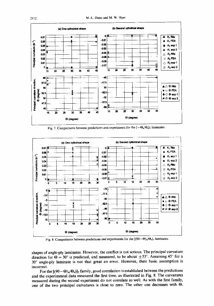
Fig. 8. Comparisons between predictions and experiments for the [(90- O)4/O4[ T laminates.
shapes of angle-ply laminates. However, the conflict is not serious. The principal curvature direction for O = 30 ° is predicted, and measured, to be about _ 53 °. Assuming 45 ° for a 30 ° angle-ply laminate is not that great an error. However, their basic assumption is
incorrect. For the [ ( 9 0 - O)4/O4)]T family, good correlation is established between the predictions
and the experimental data measured the first time, as illustrated in Fig. 8. The curvatures measured during the second experiment do not correlate as well. As with the first family, one of the two principal curvatures is close to zero. The other one decreases with 19,

Thermally-induced deformation behavior 2113
3
2 !2 1
(a) One oyllndrlcsI shape (b) Second o/li~ltleel s ~ l ~
~ , ,
0 5 10 15 20 25 30 0 " 5 10 . . . . 15 ''20 ''25 30
J
0 5 10 15 20 25 . . . . 3 0 0
O ~eoree)
5 10 ' ' 15 ' 20 25 '
O(degme)
30
• K1Rnz u K~ FIE~A
• K I~p l dr K1 mop 2 z3 K2F~z D K2FEA 0 K2 exP 1
,~, K2 exp 2
[ A~ • Rnz ] u D e F ~ 0~) e~pl ~ r ~ exp2J
Fig. 9. Comparisons between predictions and experiments for the [(O--90)4/®4]T laminates.
becoming zero at ® = 45 °, which corresponds toa flat laminate. The measurements for the principal curvature direction correlate fairly well with :the predictions.
Finally, the results for the [(90-0),/O4]r family are presented in Fig. 9. The cor- relations between the present theory and the first experimental results are excellent. The curvatures measured during the second experiment are, as observed previously, smaller. While for a given shape one of the two principal curvatures remains close to zero, the other takes a large value which remains stationary as O increases. For O = 0, the laminate is a cross-ply. The major principal curvature is close to 0.07 in-1, and the principal curvature direction is equal to zero. As O increases, the laminate becomes a cross-ply rotated in the laminate coordinate system by an angle equal to O. The major principal curvature stays close to the curvature of the cross-ply laminate. The principal curvature direction, (I), is actually equal to O or O - 9 0 , depending on the cylindrical shape considered.
Comparisons of the overall shapes The measured curvatures in Figs 7-9 were evaluated using a fit function on the out-
of-plane displacement. It is of valuable to directly compare the out-of-plane displacement measurements with the displacements w°(x, y) computed by the theory. For each laminate, using Mathematica, a three-dimensional Surfaceplot was created directly from the measured out-of-plane deflection data. This surface plot was superposed on a three-dimensional representation of the function w°(x,y) usit~predieted values of a, b and c. The results for a few laminates are shown in Figs 10-13. In the figures the scale chosen exaggerates the out-of-plane deflections so the surface shapes are not representative of the actual shapes. Also, the breakup of the surface grid in the figures is due to the slight overlap of the surfaces in certain regions. In some figures, surface plots from some finite element analyses are also represented, and will be discussed later.
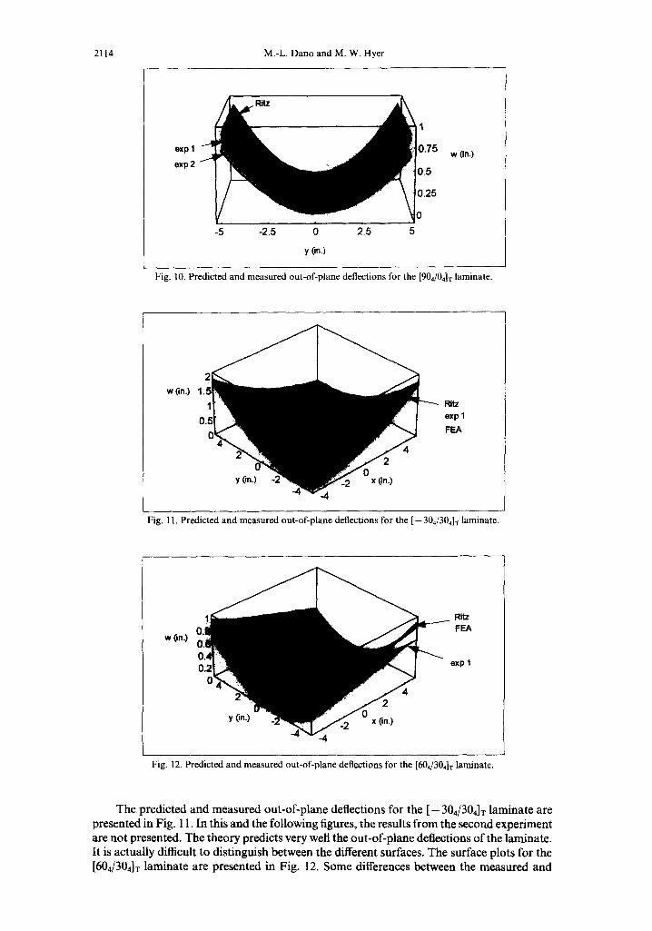
Figure 10 represents the out-of-plane deflection for the cross-ply [904/04]x laminate. The predictions by the present theory correlate very well with the deflections measured during the first experiment. Some differences in the magnitude can be noted at the edges. The deflections measured six months later are lower, as noted previously. The deflections measured the second time are systematically lower for all laminates. Reasons for these differences are not obvious. It may be possible that relaxation of the epoxy-matrix occurred during the dapsed time, leading to a decrease in the laminate curvatures.
2114 M.-L. Dano and M. W. Hyer
exp I w (in.)
exp 2
-5 -2.5 0 2.5 5
y ( in. )
Fig. 10. Predicted and measured out-of-plane deflections for the [904/04] T laminate.
w (in.) /
Fig. 11. Predicted and measured out-of-plane deflections for the [ - 304/304]a ~ laminate.
w (in.)
.4. I .
R i t z
F E A
exp I
Fig. 12. Predicted and measured out-of-plane deflections for the [604/304]r laminate.
The predicted and measured out-of-plane deflections for the [-304/304]T laminate are presented in Fig. 11. In this and the following figures, the results from the second experiment are not presented. The theory predicts very well the out-of-plane deflections of the laminate. It is actually difficult to distinguish between the different surfaces. The surface plots for the [604/304]T laminate are presented in Fig. 12. Some differences between the measured and
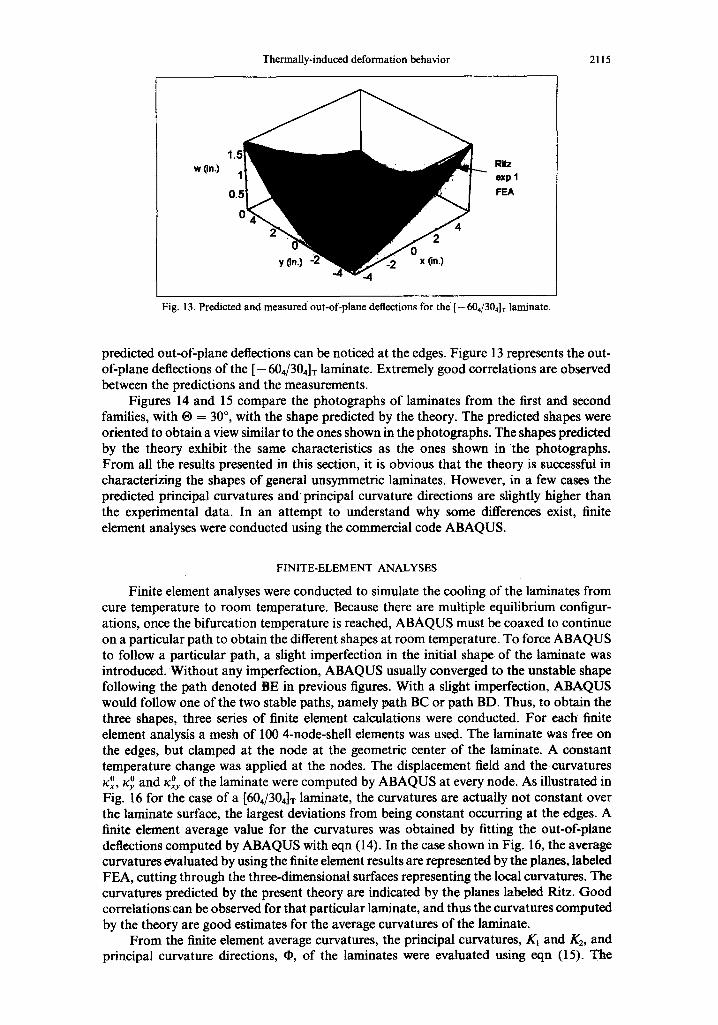
Thermally-induced deformation behavior 2115
w (in.) R ~ exp 1
FEA
Fig. 13. Predicted and measured out-of-plane deflections for the [-604/304] T laminate.
predicted out-of-plane deflections can be noticed at the edges. Figure 13 represents the out- of-plane deflections of the [ - 604/304]T laminate. Extremely good correlations are observed between the predictions and the measurements.
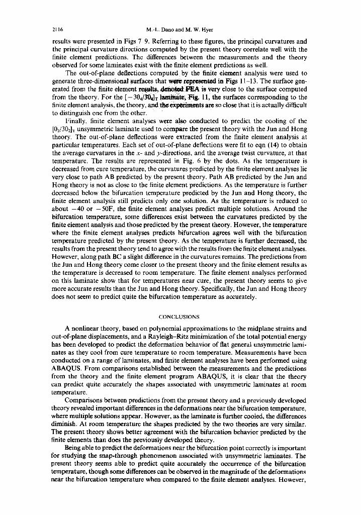
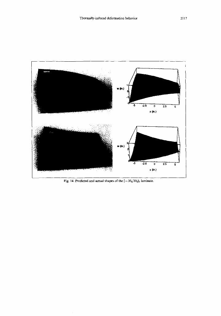
Figures 14 and 15 compare the photographs of laminates from the first and second families, with ® = 30 °, with the shape predicted by the theory. The predicted shapes were oriented to obtain a view similar to the ones shown in the photographs. The shapes predicted by the theory exhibit the same characteristics as the ones shown in the photographs, From all the results presented in this section, it is obvious that the theory is successful in characterizing the shapes of general unsymmetric laminates. However, in a few cases the predicted principal curvatures and principal curvature directions are slightly higher than the experimental data. In an attempt to understand why some differences exist, finite element analyses were conducted using the commercial code ABAQUS.
FINITE-ELEMENT ANALYSES
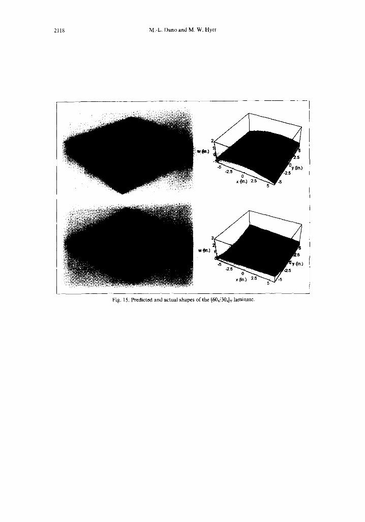
Finite element analyses were conducted to simulate the cooling of the laminates from cure temperature to room temperature. Because there are multiple equilibrium configur- ations, once the bifurcation temperature is reached, ABAQUS must be coaxed to continue on a particular path to obtain the different shapes at room temperature. To force ABAQUS to follow a particular path, a slight imperfection in the initial shape of the laminate was introduced. Without any imperfection, ABAQUS usually converged to the unstable shape following the path denoted BE in previous figures. With a slight imperfection, ABAQUS would follow one of the two stable paths, namely path BC or path BD. Thus, to obtain the three shapes, three series of finite element calculations were conducted. For each finite element analysis a mesh of 100 4-node-shell elements was used. The laminate was free on the edges, but clamped at the node at the geometric center of the laminate. A constant temperature change was applied at the nodes. The displacement field and the curvatures
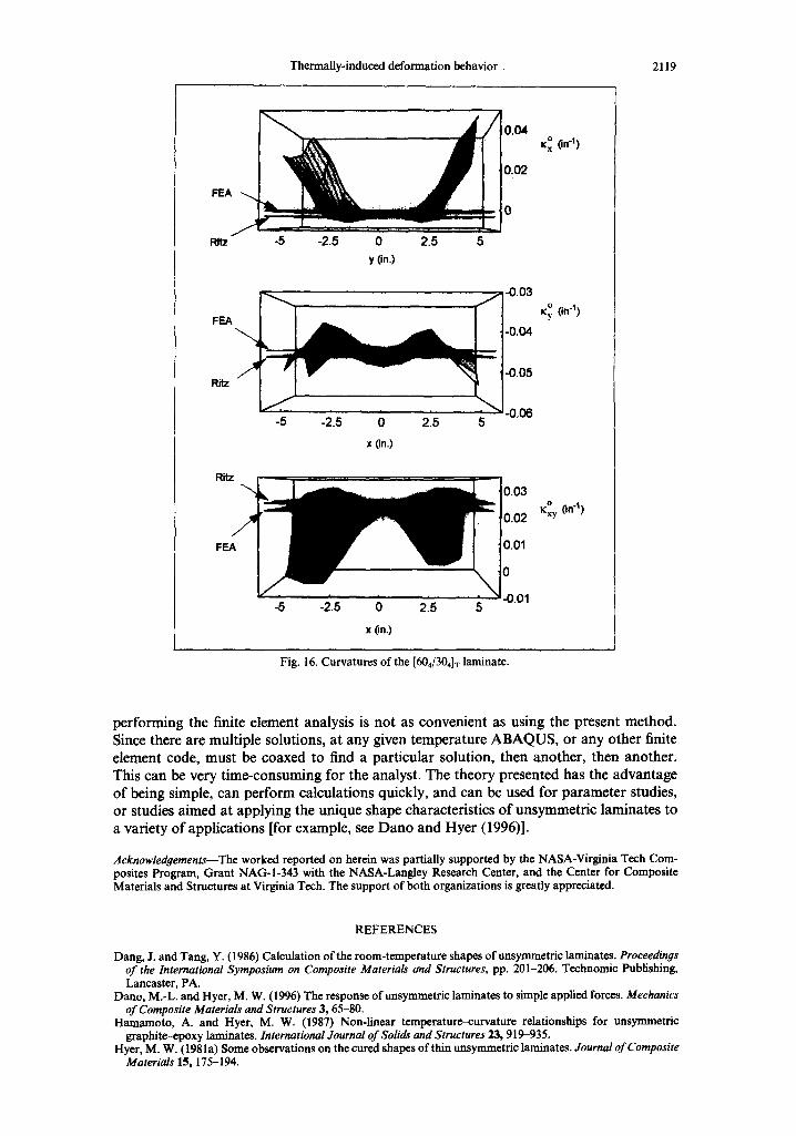
0 0 and 0 xx, xy xxy of the laminate were computed by ABAQUS at every node. As illustrated in Fig. 16 for the case of a [60d304]r laminate, the curvatures are actually not constant over the laminate surface, the largest deviations from being constant occurring at the edges. A finite element average value for the curvatures was obtained by fitting the out-of-plane deflections computed by ABAQUS with eqn (14). In the case shown in Fig. 16, the average curvatures evaluated by using the finite element results are represented by the planes, labeled FEA, cutting through the three-dimensional surfaces representing the local curvatures. The curvatures predicted by the present theory are indicated by the planes labeled Ritz. Good correlations can be observed for that particular laminate, and thus the curvatures computed by the theory are good estimates for the average curvatures of the laminate.
From the finite element average curvatures, the principal curvatures, K~ and K2, and principal curvature directions, ~, of the laminates were evaluated using eqn (15). The
2116 M.-L. Dano and M. W. Hyer
results were presented in Figs 7-9. Referring to these figures, the principal curvatures and the principal curvature directions computed by the present theory correlate well with the finite element predictions. The differences between the measurements and the theory observed for some laminates exist with the finite element predictions as well.
The out-of-plane deflections computed by the finite element analysis were used to generate three-dimensional surfaces that ~ r©pre~*~ted in Figs 11-13. The surface gen- erated from the finite element re~lts, ~ ~ is very close to the surface computed from the theory. For the [-304/304]r !_ _am~ atei F i ~ 1 I, the surfaces corresponding to the finite element analysis, the theory, and lhe experiments are so close that it is actually difficult to distinguish one from the other.
Finally, finite element analyses were also conducted to predict the cooling of the [02/302]T unsymmetric laminate used to compare the present theory with the Jun and Hong theory. The out-of-plane deflections were extracted from the finite element analysis at particular temperatures. Each set of out-of-plane deflections were fit to eqn (14) to obtain the average curvatures in the x- and y-directions, and the average twist curvature, at that temperature. The results are represented in Fig. 6 by the dots. As the temperature is decreased from cure temperature, the curvatures predicted by the finite element analyses lie very close to path AB predicted by the present theory. Path AB predicted by the Jun and Hong theory is not as close to the finite element predictions. As the temperature is further decreased below the bifurcation temperature predicted by the Jun and Hong theory, the finite element analysis still predicts only one solution. As the temperature is reduced to about - 4 0 or -50F , the finite element analyses predict multiple solutions. Around the bifurcation temperature, some differences exist between the curvatures predicted by the finite element analysis and those predicted by the present theory. However, the temperature where the finite element analyses predicts bifurcation agrees well with the bifurcation temperature predicted by the present theory. As the temperature is further decreased, the results from the present theory tend to agree with the results from the finite element analyses. However, along path BC a slight difference in the curvatures remains. The predictions from the Jun and Hong theory come closer to the present theory and the finite element results as the temperature is decreased to room temperature. The finite element analyses performed on this laminate show that for temperatures near cure, the present theory seems to give more accurate results than the Jun and Hong theory. Specifically, the Jun and Hong theory does not seem to predict quite the bifurcation temperature as accurately.
CONCLUSIONS
A nonlinear theory, based on polynomial approximations to the midplane strains and out-of-plane displacements, and a Rayleigh-Ritz minimization of the total potential energy has been developed to predict the deformation behavior of fiat general unsymmetric lami- nates as they cool from cure temperature to room temperature. Measurements have been conducted on a range of laminates, and finite element analyses have been performed using ABAQUS. From comparisons established between the measurements and the predictions from the theory and the finite element program ABAQUS, it is clear that the theory can predict quite accurately the shapes associated with unsymmetric laminates at room temperature.
Comparisons between predictions from the present theory and a previously developed theory revealed important differences in the deformations near the bifurcation temperature, where multiple solutions appear. However, as the laminate is further cooled, the differences diminish. At room temperature the shapes predicted by the two theories are very similar. The present theory shows better agreement with the bifurcation behavior predicted by the finite elements than does the previously developed theory.
Being able to predict the deformations near the bifurcation point correctly is important for studying the snap-through phenomenon associated with unsymmetric laminates. The present theory seems able to predict quite accurately the occurrence of the bifurcation temperature, though some differences can be observed in the magnitude of the deformations near the bifurcation temperature when compared to the finite element analyses. However,
Thermally-induced deformation behavior 2117
w (In.)
-2.b 0
x On.)
2.5
w On.)
-2.~ 0 2.5
X (in.)
Fig. 14. Predicted and actual shapes of the [-304/304]T laminate.
2118 M.-L. Dano and M. W. Hyer
wO..)
Fig. 15. Predicted and actual shapes of the [604/304]-r laminate.
Thermally-induced deformation behavior. 2119
FE/
PJtz
FEA
Ritz
Rit-
FE
-5
-5
-5
-2.5 0 2.5 5 y (in.)
-2.5 0 2.5
x (in.)
-2.5 0 2.5 5
x (in.)
0.04
0.02
-0.03
-0.04
-0.05
-0.06 5
0.03
0.02
0.01
0
-0.01
O ~:x (i n'1)
0 ry On "1)
O
ICxy On "I)
Fig. i 6. Curvatures of the [604/304]T laminate.
performing the finite element analysis is not as convenient as using the present method. Since there are multiple solutions, at any given temperature ABAQUS, or any other finite element code, must be coaxed to find a particular solution, then another, then another. This can be very time-consuming for the analyst. The theory presented has the advantage of being simple, can perform calculations quickly, and can be used for parameter studies, or studies aimed at applying the unique shape characteristics of unsymmetric laminates to a variety of applications [for example, see Dano and Hyer (1996)].
Acknowledgements---The worked reported on herein was partially supported by the NASA-Virginia Tech Com- posites Program, Grant NAG-I-343 with the NASA-Langley Research Center, and the Center for Composite Materials and Structures at Virginia Tech. The support of both organizations is greatly appreciated.
REFERENCES
Dang, J. and Tang, Y. (1986) Calculation oftbe room-temperature shapes of unsymmetric laminates. Proceedings of the International Symposium on Composite Materials and Structures, pp. 201-206. Technomic Publishing, Lancaster, PA.
Dano, M.-L. and Hyer, M. W. (1996) The response of unsymmetric laminates to simple applied forces. Mechanics of Composite Materials and Structures 3, 65-80.
Hamamoto, A. and Hyer, M. W. (1987) Non-linear temperature-curvature relationships for unsymmetric graphite-epoxy laminates. International Journal of Solids and Structures 23, 919-935.
Hyer, M. W. (1981a) Some observations on the cured shapes of thin unsymmetric laminates. Journal of Composite Materials 15, 175-194.
2120 M.-L. Dano and M. W. Hyer
Hyer, M. W. (198 lb) Calculations of the room-temperature shapes ofunsymmetric laminates. JournalofComposite Materials 15, 296-310.
Hyer, M. W. (1982) The room-temperature shapes of four-layer unsymmetric cross-ply laminates. Journal of Composite Materials 16, 318-340.
Jones, R. M. (1975) Mechanics of Composite Materials. Mc Graw-Hill, New York. Jun, W. J. and Hong, C. S. (1990) Effect of ~sidual shear strain on the cured shape of unsymmetric cross-ply thin
laminates. Journal of Composite Science and Technology 38, 55--67. Jun, W. J. and Hong, C. S. (1992) Cured s ~ of unsymmetric laminates with arbitrary lay-up angles. Journal of
Reinforced Plastics and Composites II, 1352-1366. Peeters, L. J. B., Powell, P. C. and Warnet, L. (1996)Thermally-induced shapes of unsymmetric laminates. Journal
of Composite Materials 30, 603-626. Schlecht, M., Schulte, K. and Hyer, M. W. (1995) Advanced calculations of the room-temperature shapes of thin
unsymmetric composite laminates. Composite Structures 32, 627-633. Wolfram, S. (1991) Mathematica : A System for Doing Mathematics by Computer. Addison-Wesley, Redwood
City, CA.