thermal dispersion mass flow measurement
TRANSCRIPT
S p e c i a l A p p l i c at i o n S e r i e s
THERMATEL® MASS FLOW MEASUREMENT
� Mass Flow Measurement
Thermal flow meters measure flow rate in units ofmass flow (SCFM or NM3/hr) rather than flow at oper-ating conditions. Because temperature and pressurevariations will influence the gas density, mass flowmeasurement provides optimum measurement accuracydespite temperature and pressure variations.
In addition to greater measurement accuracy, massflow is also measured to accommodate an industry’smeasurement standards. Chemicals react on the basisof mass relationships of ingredients. Combustion isbased upon the mass flow rate of the air and fuel. Inaddition, a facility’s gas consumption is based uponmass flow.
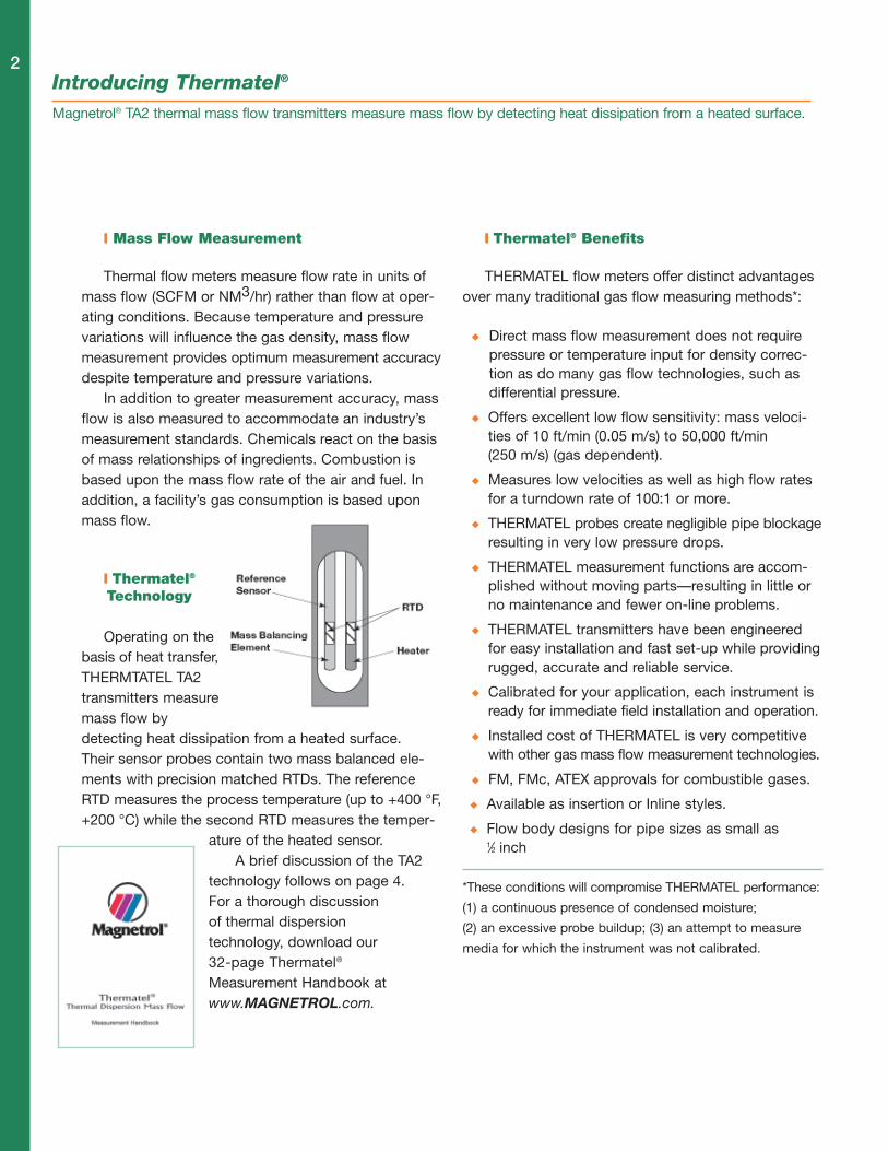
� Thermatel®
Technology
Operating on thebasis of heat transfer,THERMTATEL TA2transmitters measuremass flow bydetecting heat dissipation from a heated surface.Their sensor probes contain two mass balanced ele-ments with precision matched RTDs. The referenceRTD measures the process temperature (up to +400 °F,+200 °C) while the second RTD measures the temper-
ature of the heated sensor.A brief discussion of the TA2
technology follows on page 4.For a thorough discussionof thermal dispersiontechnology, download our32-page Thermatel®
Measurement Handbook atwww.MAGNETROL.com.
� Thermatel® Benefits
THERMATEL flow meters offer distinct advantagesover many traditional gas flow measuring methods*:
� Direct mass flow measurement does not requirepressure or temperature input for density correc-tion as do many gas flow technologies, such asdifferential pressure.
� Offers excellent low flow sensitivity: mass veloci-ties of 10 ft/min (0.05 m/s) to 50,000 ft/min(250 m/s) (gas dependent).
� Measures low velocities as well as high flow ratesfor a turndown rate of 100:1 or more.
� THERMATEL probes create negligible pipe blockageresulting in very low pressure drops.
� THERMATEL measurement functions are accom-plished without moving parts—resulting in little orno maintenance and fewer on-line problems.
� THERMATEL transmitters have been engineeredfor easy installation and fast set-up while providingrugged, accurate and reliable service.
� Calibrated for your application, each instrument isready for immediate field installation and operation.
� Installed cost of THERMATEL is very competitivewith other gas mass flow measurement technologies.
� FM, FMc, ATEX approvals for combustible gases.
� Available as insertion or Inline styles.
� Flow body designs for pipe sizes as small as1⁄2 inch
*These conditions will compromise THERMATEL performance:
(1) a continuous presence of condensed moisture;
(2) an excessive probe buildup; (3) an attempt to measure
media for which the instrument was not calibrated.
Introducing Thermatel®
Magnetrol® TA2 thermal mass flow transmitters measure mass flow by detecting heat dissipation from a heated surface.
2
3
Supply Voltage: 100-264 VAC, 50-60 Hz11.6-30 VDC
Flow Range: 10-50,000 SFPM (0.05-250 Nm/s)(gas dependent)
Flow Accuracy: ±1% of reading plus 0.5%of calibration range
Temperature Accuracy: ±2° F (1° C)
Repeatability: ±0.5% of reading
Sensor Range: -50° to +400° F (-45° to +200° C)Rated to 1,500 psig (103 bar)
Turn Down: 100:1 (application dependent)
TA2 S P E C I F I C A T I O N S
TA2 I N D E P T H
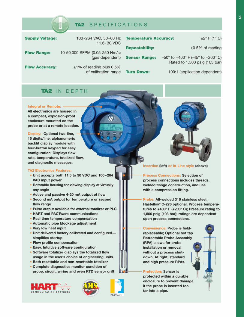
Integral or Remote:All electronics are housed ina compact, explosion-proofenclosure mounted on theprobe or at a remote location.
Display: Optional two-line,16 digits/line, alphanumericbacklit display module withfour-button keypad for easyconfiguration. Displays flowrate, temperature, totalized flow,and diagnostic messages.
TA2 Electronics Features:• Unit accepts both 11.5 to 30 VDC and 100–264VAC input power• Rotatable housing for viewing display at virtuallyany angle• Active and passive 4-20 mA output of flow• Second mA output for temperature or secondflow range• Pulse output available for external totalizer or PLC• HART and PACTware communications• Real time temperature compensation• Automatic pipe blockage adjustment• Very low heat input• Unit delivered factory calibrated and configured—simplifies startup• Flow profile compensation• Easy. Intuitive software configuration• Software totalizer displays the totalized flowusage in the user’s choice of engineering units.• Both resettable and non-resettable totalizer• Complete diagnostics monitor condition ofprobe, circuit, wiring and even RTD sensor drift
Insertion (left) or In-Line style (above)
Process Connections: Selection ofprocess connections includes threads,welded flange construction, and usewith a compression fitting.
Probe: All-welded 316 stainless steel;Hastelloy® C-276 optional. Process tempera-tures to +400° F (+200° C); Pressure rating to1,500 psig (103 bar); ratings are dependentupon process connections.
Convenience: Probe is field-replaceable; Optional hot tapRetractable Probe Assembly(RPA) allows for probeinstallation or removalwithout a process shut-down. At right, standardand high pressure RPAs.
Protection: Sensor isprotected within a durableenclosure to prevent damageif the probe is inserted toofar into a pipe.
�
�
�
�
�
�
4Principle of OperationTA2 thermal mass flow transmitter technology for measuring mass flow.
The TA2 uses the proven Constant TemperatureDifference Technology for mass flow measurement.There are two elements in the sensor as shown onpage 2. The RTD in the reference pin measures theprocess temperature of the gas where the sensor islocated; a variable amount of power is applied to theheater in the second pin to maintain a specifiedtemperature difference. The amount of the temperaturedifference is set during the calibration to optimize theperformance for the particular application.
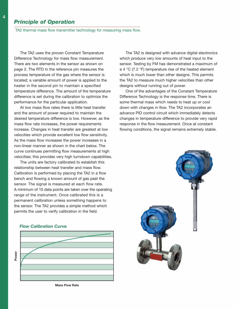
At low mass flow rates there is little heat transferand the amount of power required to maintain thedesired temperature difference is low. However, as themass flow rate increases, the power requirementsincrease. Changes in heat transfer are greatest at lowvelocities which provide excellent low flow sensitivity.As the mass flow increases the power increases in anon-linear manner as shown in the chart below. Thecurve continues permitting flow measurements at highvelocities; this provides very high turndown capabilities.
The units are factory calibrated to establish thisrelationship between heat transfer and mass flow.Calibration is performed by placing the TA2 in a flowbench and flowing a known amount of gas past thesensor. The signal is measured at each flow rate.A minimum of 10 data points are taken over the operatingrange of the instrument. Once calibrated this is apermanent calibration unless something happens tothe sensor. The TA2 provides a simple method whichpermits the user to verify calibration in the field.
The TA2 is designed with advance digital electronicswhich produce very low amounts of heat input to thesensor. Testing by FM has demonstrated a maximum ofa 4 °C (7.2 °F) temperature rise of the heated elementwhich is much lower than other designs. This permitsthe TA2 to measure much higher velocities than otherdesigns without running out of power.
One of the advantages of the Constant TemperatureDifference Technology is the response time. There issome thermal mass which needs to heat up or cooldown with changes in flow. The TA2 incorporates anadvance PID control circuit which immediately detectschanges in temperature difference to provide very rapidresponse in the flow measurement. Once at constantflowing conditions, the signal remains extremely stable.
Mass Flow Rate
Po
wer
Flow Calibration Curve

Measuring Mass Flow in Large Pipes and Ducts.
ABOVE: Two, custom-engineeredmulti-point arrays. BELOW: Fourstandard TA2 flow meters.
he larger the diameter of apipe, stack or duct, the
greater the likelihood of significantflow velocity profile distortions. Inthese highly skewed flow condi-tions, a single point flow meterwon’t do the job. So, what’s thebest measurement solution?
A frequent choice for greatermeasurement accuracy is themulti-point sensor array. Here,two or more flow sensors areplaced along an extended-lengthinsertion element. With more sen-sor points across the interiorexpanse of the duct, the morerepresentative will be the flowmeasurement. And, if you installtwo of these arrays in crisscross
fashion inside the duct (as dia-gramed at top right), you have asensor array that will provide verygood results. The price you payfor this set-up, however, is cost;for the multi-point array is engi-neering-intensive at the front end,and maintenance-intensive downthe line.
Option #2 is to insert four TA2s(or more, as needed) from oppo-site sides of a duct (bottom right)and average their output signals.This approach uses standardTHERMTATEL flow meters foraccurate and reliable mass flowmeasurement at a lower installedcost, and with less maintenanceheadaches in the future. �
T
Mass Flow of AirApplications: The flow of air (78% nitrogen, 21%
oxygen and traces of eight other gases) is monitored in
nearly all industrial settings, including applications for
processing; air/gas mixing; cooling; blowing & drying;
combustion; aeration; ventilation; filtration; ingredient
mixing; air sampling, and many others. Significant air-
flow variables include pipe diameters, wide flow ranges,
varying velocities and low flow sensitivity. Large-duct
flow applications for THERMATEL include combustion
air flow used in determining fuel-to-air mixtures for
industrial boilers, heaters, furnaces and kilns.
TA2 Air Flow Applications:
• Aeration Flows Wastewater Treatment• Combustion Air Boilers, Kilns, Heaters• Test Air Flow Pump and Equipment Mfgrs.• Air Flow Rate Metals Processing and Recovery• Spray Drying Food, Bio-Pharm, Chemical• Remediation Agricultural, Environmental• Heat Treating Manufacturing, Metals• Drying Air Flow Pulp and Paper• Reheat Air Flow PowerGen• Leak Detection All Industries
The combustion efficiency of burners, furnaces anddryers is enhanced by obtaining repeatable flow meas-urement of the inlet combustion air. Ducts can vary fromsix-inches in diameter to many square feet. Too little airand combustion is incomplete; too much air and com-bustion efficiency is greatly reduced.
Application Insights
5
Compressed Air FlowApplications: Air that is compressed and contained
at a pressure greater than atmosphere has become
industry’s universal power source. Seventy percent of
all manufacturers operate compressed air (CA).
Process operations dependent upon CA include pneu-
matic tools; materials handling; painting; oxidation;
fractionation; cryogenics; refrigeration; dehydration;
filtration and aeration. Flow meters help ensure effi-
cient operation at rated SCFM output and are also
used to detect leaks. A Flow Meter with a Totalizer
provides an accurate measurement of CA consumption.
TA2 Compressed Air Flow Applications:
• Automation & Process Systems All Industries• Pneumatic tools, Painting All Industries• Materials Handling Systems All Industries• Filling, Capping, Packaging Bottling, Packaging• PET, PE Bottle Blowing Plastic Containers• Labs, Pill Coating Pharmaceuticals• Soil Remediation Environmental Industry• Drilling, Pipelines Oil and Natural Gas• Pressurizing Gas Lines Natural Gas• Food & Drug Processing Foods, Pharmaceuticals
Nitrogen Gas FlowApplications: Nitrogen gas (N2) is the most widely
used commercial gas. Colorless, odorless, tasteless,
and nonflammable, its inertness makes it an ideal
blanketing gas to protect flammable or explosive
solids and liquids from contact with air. Keeping
chemicals, pharmaceuticals and foods within a nitro-
gen atmosphere keeps them protected from oxygen
and moisture degradation. Oil, gas and petrochemical
industries purge tanks and pipes with nitrogen to
replace hazardous or undesirable atmospheres. In
refinery maintenance, nitrogen quickly cools catalyst
temperatures to vastly reduce shutdown time.
TA2 Nitrogen Gas Flow Applications:
• Tank Blanketing Chemicals, Foods, HydrocarbonsBio-Pharm, Semi-Conductor
• Gas Purging Natural Gas, Refinery Industries• Pressure Transfer Storage Vessels, All Industries• Cooling, Freezing Refineries, Food Processing• Forming Control Metal Casting• Heat Treatment Shield Gas for Steel and Iron• Pill & Tablet coating Pharmaceutical, Nutritional• Inerting of LNG Tankers, Transport Vessels• Drilling, Processing Oil and Natural Gas Industries
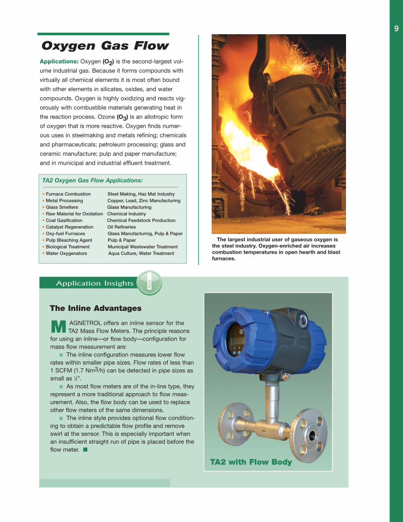
Nitrogen flow in a two-inch line at a chemical plant.Point-of-use consumption of compressed air and gaseswill permit the user to obtain improved usage rate infor-mation for more efficient operations. Some centralizedfacilities bill the individual plants for gas usage.
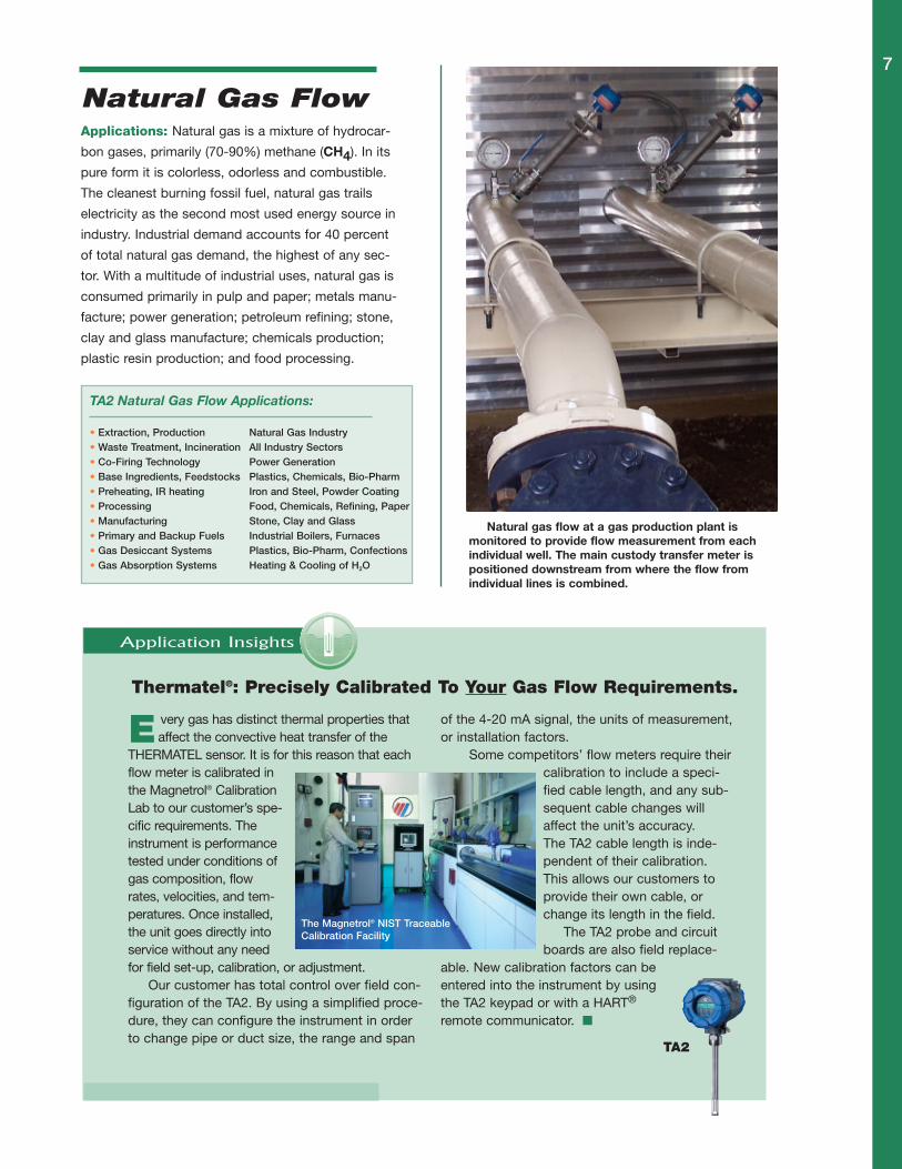
This Glycol Regeneration Skid serving a natural gasfield in Holland features three TA2s—two measuring airflow to an incinerator and one measuring natural gas.
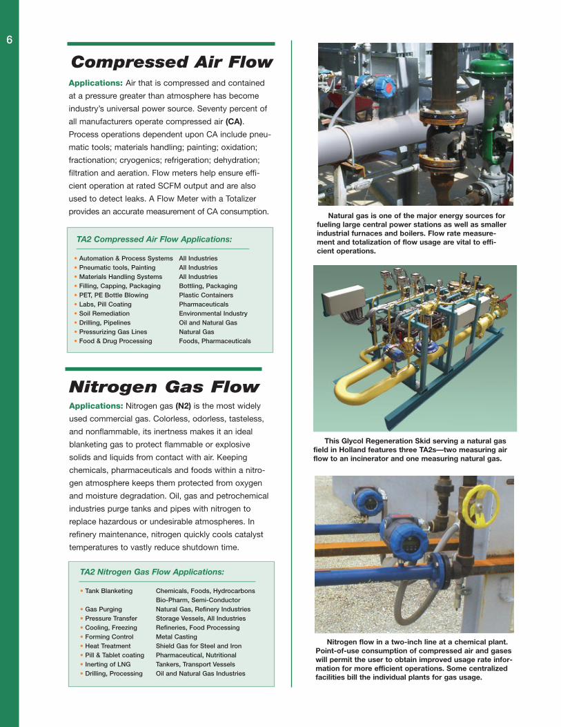
Natural gas is one of the major energy sources forfueling large central power stations as well as smallerindustrial furnaces and boilers. Flow rate measure-ment and totalization of flow usage are vital to effi-cient operations.
6
Thermatel®: Precisely Calibrated To Your Gas Flow Requirements.
very gas has distinct thermal properties thataffect the convective heat transfer of the
THERMATEL sensor. It is for this reason that eachflow meter is calibrated inthe Magnetrol® CalibrationLab to our customer’s spe-cific requirements. Theinstrument is performancetested under conditions ofgas composition, flowrates, velocities, and tem-peratures. Once installed,the unit goes directly intoservice without any needfor field set-up, calibration, or adjustment.
Our customer has total control over field con-figuration of the TA2. By using a simplified proce-dure, they can configure the instrument in orderto change pipe or duct size, the range and span
of the 4-20 mA signal, the units of measurement,or installation factors.
Some competitors’ flow meters require theircalibration to include a speci-fied cable length, and any sub-sequent cable changes willaffect the unit’s accuracy.The TA2 cable length is inde-pendent of their calibration.This allows our customers toprovide their own cable, orchange its length in the field.
The TA2 probe and circuitboards are also field replace-
able. New calibration factors can beentered into the instrument by usingthe TA2 keypad or with a HART®
remote communicator. �
TA2
The Magnetrol® NIST TraceableCalibration Facility
E
Natural Gas FlowApplications: Natural gas is a mixture of hydrocar-
bon gases, primarily (70-90%) methane (CH4). In its
pure form it is colorless, odorless and combustible.
The cleanest burning fossil fuel, natural gas trails
electricity as the second most used energy source in
industry. Industrial demand accounts for 40 percent
of total natural gas demand, the highest of any sec-
tor. With a multitude of industrial uses, natural gas is
consumed primarily in pulp and paper; metals manu-
facture; power generation; petroleum refining; stone,
clay and glass manufacture; chemicals production;
plastic resin production; and food processing.
TA2 Natural Gas Flow Applications:
• Extraction, Production Natural Gas Industry• Waste Treatment, Incineration All Industry Sectors• Co-Firing Technology Power Generation• Base Ingredients, Feedstocks Plastics, Chemicals, Bio-Pharm• Preheating, IR heating Iron and Steel, Powder Coating• Processing Food, Chemicals, Refining, Paper• Manufacturing Stone, Clay and Glass• Primary and Backup Fuels Industrial Boilers, Furnaces• Gas Desiccant Systems Plastics, Bio-Pharm, Confections• Gas Absorption Systems Heating & Cooling of H2O
Natural gas flow at a gas production plant ismonitored to provide flow measurement from eachindividual well. The main custody transfer meter ispositioned downstream from where the flow fromindividual lines is combined.
Application Insights
7

Hydrogen Gas FlowApplications: Hydrogen (H2), the lightest of gases, is
colorless, odorless, tasteless, flammable and nontoxic
(at atmosphere). It has the highest combustion energy
release per unit of weight of any commonly occurring
material. Hydrogen’s industrial applications include
chemical processing; metal production; petroleum
refining; electronics; power; pharmaceuticals and
foods. With the development of a viable fuel cell tech-
nology, new application opportunities in the automo-
tive sector will no doubt surface. Consideration must
be given to Hydrogen’s volatility and its greater cooling
effect on the sensor compared to other gases.
TA2 Hydrogen Gas Flow Applications:
• Treating, Welding, Annealing Steel, Stainless Steel, Copper• Hydrodesulfurization Oil Refineries• Catalytic Cracking Oil Refineries• Vitamin Manufacturing Pharmaceuticals, Supplements• Oxidation Preventative Glass Manufacturing• Hydrogenation of Fatty Acids Food and Dairy• Carrier Gas Integrated Circuits• Generator Coolant Power Generation• Rocket Fuel, Fuel Cells Aerospace, Automotive• Making NH3, CH3OH, H2O2 Chemicals, Polymers, Solvents
Argon Gas FlowApplications: Composing slightly less than 1% of the
air, Argon (Ar) is a colorless, odorless, tasteless, non-
corrosive, nonflammable, and nontoxic gas. It is the
most abundant of the “rare” gases, those with an
extremely weak tendency to chemically interact with
other materials. Argon is commercially valued in multi-
industry applications for its near total inertness and low
cost. Argon is utilized to produce specialty products;
protect and maintain product quality; and lower operat-
ing costs in steelmaking. It is essential in metal fabrica-
tion; light bulbs; the production of electronic equipment;
and in thermal glass and plastics manufacture.
TA2 Argon Gas Flow Applications:
• Degasification Aluminum, Titanium, Stainless Steel• Heat Transfer Electronics, Semiconductors• Bulb Media Fluorescent, Incandescent Lighting• Thermal Media Thermopane Window Manufacturing• Argon Lasers DNA Sequencing, Electronics, Printing• Arc, Tig, Mig Welding Manufacturing, Metal Fabrication• Filler Gas Silicone and Germanium Manufacturing• Gas-plasma Treating Plastics, Painting and Coating• Spectrometry Anodizing, Plating, Powder Coating• Cryoablation Medical technology
Retractable Probe Assemblies (RPAs) permit installa-tion of the instrument in applications which must remainin continuous operation. RPA designs with pressure rat-ings up to 720 psi are available.
Hydrogen gas has many industrial applications. Usinga catalyst and large quantities of hydrogen, hydrotreat-ment (above) removes 90% of the sulfur, oxygen, nitrogenand metals from gasoline refinery feedstocks.
The flow of large ducts and stacks, as in this powergeneration boiler, can be measured using multiple stan-dard TA2 units to obtain an averaging of the flow rate.This approach is more economical and easier to maintainthan custom-designed, multiple-point array systems.
8
Oxygen Gas FlowApplications: Oxygen (O2) is the second-largest vol-
ume industrial gas. Because it forms compounds with
virtually all chemical elements it is most often bound
with other elements in silicates, oxides, and water
compounds. Oxygen is highly oxidizing and reacts vig-
orously with combustible materials generating heat in
the reaction process. Ozone (O3) is an allotropic form
of oxygen that is more reactive. Oxygen finds numer-
ous uses in steelmaking and metals refining; chemicals
and pharmaceuticals; petroleum processing; glass and
ceramic manufacture; pulp and paper manufacture;
and in municipal and industrial effluent treatment.
TA2 Oxygen Gas Flow Applications:
• Furnace Combustion Steel Making, Haz Mat Industry• Metal Processing Copper, Lead, Zinc Manufacturing• Glass Smelters Glass Manufacturing• Raw Material for Oxidation Chemical Industry• Coal Gasification Chemical Feedstock Production• Catalyst Regeneration Oil Refineries• Oxy-fuel Furnaces Glass Manufacturing, Pulp & Paper• Pulp Bleaching Agent Pulp & Paper• Biological Treatment Municipal Wastewater Treatment• Water Oxygenators Aqua Culture, Water Treatment
The largest industrial user of gaseous oxygen isthe steel industry. Oxygen-enriched air increasescombustion temperatures in open hearth and blastfurnaces.
9
The Inline Advantages
AGNETROL offers an inline sensor for theTA2 Mass Flow Meters. The principle reasons
for using an inline—or flow body—configuration formass flow measurement are:
� The inline configuration measures lower flowrates within smaller pipe sizes. Flow rates of less than1 SCFM (1.7 Nm3/h) can be detected in pipe sizes assmall as 1⁄2".
� As most flow meters are of the in-line type, theyrepresent a more traditional approach to flow meas-urement. Also, the flow body can be used to replaceother flow meters of the same dimensions.
� The inline style provides optional flow condition-ing to obtain a predictable flow profile and removeswirl at the sensor. This is especially important whenan insufficient straight run of pipe is placed before theflow meter. �
M
TA2 with Flow Body
Application Insights

Carbon Dioxide Gas FlowApplications: Carbon dioxide (CO2) is an odorless,
colorless, non-combustible and slightly toxic gas with a
pungent acidic taste. It constitutes a fraction of our air,
about 0.036%. Carbon dioxide is valued in industry for
its reactivity, inertness and ability to create cold condi-
tions. Large quantities of gaseous CO2 are produced
and consumed in making fertilizers, plastic resins, and
rubber. Other important uses include beverage carbon-
ation; food and pharmaceutical processing; enhance-
ment of oil recovery from oil wells; a raw material for
producing many chemicals; treatment of alkaline water;
and manufacturing CO2 fire extinguishing systems.
TA2 Carbon Dioxide Flow Applications:
• MIG/MAG Welding Shield Metal Industries• Casting Mold Hardening Metal Industries• Dry-Ice Feed Manufacturing, Construction• Urea, Methanol Production Chemical Industry• Oil Extraction Well Priming Petroleum Industry• Flash Removal Rubber and Plastics• Dry Ice & CO2 Coolant Food and Beverages• Beverage Carbonation Soft Drinks, Beer, Sparkling Wine• Blanketing Agent Foods, Pharmaceuticals• Fertilizer Processing Agricultural Chemicals
Exhaust & Waste GasApplications: Exhaust gases in a wide variety of com-
positions range from the ecologically benign to toxic
emissions. Off-gases are vapors emitted from extraction
and treatment systems that are discharged directly to the
atmosphere, captured or destroyed. Hydrocarbon gases
from industrial operations are often “flared” in a high-
temperature oxidation process which burns combustible
components of waste. Natural gas, propane, ethylene,
propylene, butadiene and butane constitute over 95 per-
cent of the waste gases flared. Consideration must be
given to changes in gas composition, abruptness of flow
change, low pressures, and a wide range of velocities.
TA2 Exhaust & Waste Gas Applications:
• Vent Lines All Industries• Waste CO2 Petrochemicals, Chemical Production• SO2 Off-Gas Metals, Chemicals, Pharmaceuticals• Flare Stacks, Headers Oil Platforms, Refineries; Chemicals• Flue Gas Power Generation• Waste-to-Energy Gas Landfill, Waste Treatment Plant• Waste Flow Mixing Incinerators, All Industries• Flare Gas Recovery Electricity, Steam, Hot Water Generation• NC Gas Disposal Pulp and Paper
Due to environmental laws and restrictions, oil andgas platform operators must monitor and report theamount of flared gases. The consistent composition, lowflow sensitivity, and high turndown capabilities make theTA2 an ideal flow meter for this service.
Measuring natural gas flow to a furnace. The use of aninsertion probe permits the TA2 to be installed in lines ofvarious sizes and with considerable installation flexibilitywhile also ensuring economical mass flow measurement.
Today’s refineries and chemical plants frequentlyburn-off waste gases in a flare line. Because both flowrates and gas compositions vary, the TA2 can be usedto obtain relative flow indication.
10

Temperature Compensation of the Mass Flow Measurement
hermal Mass Flow Transmitters measureheat transfer and infer the mass flow based
upon calibration information. The gas propertiesthat effect convective heat transfer, however, areaffected by changing temperatures.
After extensive testing and analysis on theeffect of changes in flow at different tempera-tures, MAGNETROL has developed a proprietarymethod of providing temperature compensationover the entire operating range of the instrument.
THERMATEL Flow Meters measure the temper-ature and then apply a correction in the flow meas-urement based upon the operating temperature.
The charts below show data from the TA2with and without temperature compensation.These graphs demonstrate the effectiveness ofMAGNETROL temperature compensation of themass flow measurement based upon varyinggas properties. �
Application Insights
Applications: These gases are typically composed of
65% methane (CH4) and 35% carbon dioxide (CO2).
Landfill gas (LFG) is generated from the degradation
of biodegradable wastes. Digester gas results from the
anaerobic decomposition of organic matter in munici-
pal wastewater treatment. Bio-gas is created from
livestock production, agricultural and industrial efflu-
ents and sewage treatment. Flaring and venting as
management strategies for these gases is giving way
to energy harvesting technologies with the economic
advantage of creating heat, electricity, fuel or feed-
stocks while also reducing carbon emissions that
would ordinarily result from flaring operations.
LFG, Digester & Bio-Gas
TA2 LFG, Digester & Bio-Gas Applications:
• Anaerobic Digestion Gas Municipal Wastewater Treatment• Methane Gas for Heat, Power Boilers, Power Co-Generation• Digester Gas Recirculation Wastewater Treatment• Bio-Mass to Bio-Gas Wood Scrub-to-Gas Conversion• LFG Monitoring, Harvesting Municipal Landfills• Sewer Gas Processing Municipal Treatment Systems• Displacement Digester Manure to Bio-gas Conversion• Gas Venting and Flaring Landfills and General Industry• Bio-Engine and Motor Fuel Generator, Engine Manufacturers
T
Bio-gas, a mixture of methane and carbon dioxide,results from the decomposition of organic materials andcan be harvested as a fuel source. Due to its low flowsensitivity and low pressure drop, the TA2 is an excellentflow meter for measuring bio-gases.
11

CORPORATE HEADQUARTERS5300 Belmont Road • Downers Grove, Illinois 60515-4499 USA
Phone: 630-969-4000 • Fax: 630-969-9489magnetrol.com • [email protected]
EUROPEAN HEADQUARTERSHeikensstraat 6 • 9240 Zele, Belgium
Phone: 052 45.11.11 • Fax: 052 45.09.93
BRAZIL: Av. Dr. Mauro Lindemberg Monteiro, 185, Quadrante 16 • CEP 06278-010 • Osasco • São Paulo
CANADA: 145 Jardin Drive, Units 1 & 2 • Concord, Ontario L4K 1X7
CHINA: Plant 6, No. 191, Huajin Road • Minhang District • Shanghai 201108
DEUTSCHLAND: Alte Ziegelei 2–4 • D-51491 Overath
DUBAI: DAFZA Office 5EA 722, P.O. Box 293671 • Dubai, United Arab Emirates
INDIA: C-20 Community Centre • Janakpuri, New Delhi 110 058
ITALIA: Via Arese, 12 • 20159 Milano
RUSSIA: 198095, Saint-Petersburg - Marshala Govorova
SINGAPORE: 33 Ubi Avenue 3 • #05-10 Vertex • Singapore 408868
UNITED KINGDOM: Regent Business Centre • Jubilee Road • Burgess Hill, West Sussex RH15 9TL
Magnetrol & Magnetrol logotype and Thermatel are registered trademarks of Magnetrol International, Incorporated.
HART® is a registered trademark of the HART Communication Foundation.Hastelloy® is a registered trademark of Haynes International, Inc.
Modbus® is a registered trademark of Gould, Inc.
Copyright © 2013 Magnetrol International, Incorporated. All rights reserved. Printed in the USA.
Bulletin: 54-210.3 • Effective: January 2011
S p e c i a l A p p l i c at i o n S e r i e s
PLEASE NOTE: The instruments recommended in this guide are based on
field experience with similar applications and are included as a general guide
to flow control selection. However, because all applications differ, customers
should determine suitability for their own purposes.