the use of large-diameter boreholes and downhole logging methods
TRANSCRIPT
THE USE OF LARGE-DIAMETER BOREHOLES AND DOWNHOLE LOGGING
METHODS IN LANDSLIDE INVESTIGATIONS
BY
PHILIP L. JOHNSON and WILLIAM F. COLE
COTTON, SHIRES & ASSOCIATES, INC. CONSULTING ENGINEERS AND GEOLOGISTS
ARTICLE REPRINTED FROM:
ENGINEERING GEOLOGY PRACTICEIN NORTHERN CALIFORNIA (2001): EDITED BY
HORACIO FERRIZ AND ROBERT ANDERSON, PAGES 95 - 106.
��
��
�� �
�� �
� �
��
� ��
��
� ��
� � � � � � � � � �
California Department of Conservation
Division of Mines and GeologyBulletin 210
Association of Engineering Geologists
Special Publication 12
ENGINEERING GEOLOGY PRACTICE IN NORTHERN CALIFORNIA
THE USE OF LARGE-DIAMETER BOREHOLES AND DOWNHOLE LOGGING
METHODS IN LANDSLIDE INVESTIGATIONS
ABSTRACT
Downhole logging of large-diameter borings provides distinct advantages over the logging of small-diameter borings or test pits in the subsurface investigation of landslides, in that it allows the mapping of three-dimensional structural components in situ. Because a key element in any landslide investigation is the identification of shear zones along which landslide movement has occurred, problems with core recovery during drilling severely limit the usefulness of small-diameter drilling methods. Backhoe test pits, on the other hand, allow detailed logging of in situ geologic conditions but are limited by excavation depth.
We propose a seven-step process to develop a downhole log that graphically depicts the geologic elements encountered by the borehole. This process entails: (1) drawing a preliminary cross section, (2) logging cuttings during drilling, (3) marking the intersection of the cross sectional plane with the borehole wall, (4) “hacking” the borehole wall to remove smeared materials, (5) graphically depicting the three-dimensional structure exposed on the borehole wall and describing the geologic conditions in writing, (6) sampling earth materials, and (7) modifying the cross section with data derived from the boring log.
The downhole logging method is limited with respect to depth by groundwater conditions, drilling rig depth capabilities, and borehole stability. Downhole logging is not advisable when there is potential for borehole caving, rockfall, noxious gases, oxygen-deficient atmosphere, or shallow groundwater. These constraints often can be mitigated through the use of specific downhole logging and drilling techniques combined with sound judgment on the part of an experienced downhole logger. However, under certain geologic and hydrogeologic conditions, downhole logging may not be suitable.
A landslide investigation at a winery in Napa County provides an example of the successful use of downhole logging of large-diameter borings. Downhole logging was used to confirm the existence of two ancient, deep-seated, static landslides, to determine the depth and lateral extent of static landslide deposits and to delineate the depth of a recently active landslide.
Downhole logging of large-diameter boreholes has also been used for a variety of other purposes, such as investigation of faults that are covered with a significant thickness of unfaulted strata and the study of ground subsidence.
INTRODUCTION
The subsurface investigation of landslides provides unique challenges to the engineering geologist. Landslide exploration typically focuses on the depth of the basal rupture surface along which landslide movement has occurred, the geometry of the rupture surface, the direction of movement, the strength of sheared materials, and the underlying geology. Historically, engineering geologists in northern California have relied mostly upon the logging of small-diameter borings or backhoe test pits to gather subsurface information for landslide studies. Additional information regarding the depth and direction of active landslide movement could be collected from slope inclinometers. However, these traditional methods have serious limitations in characterizing static landslides.
Test pits and trenches are helpful for investigating shallow landslides (i.e., less than 10 to 20 feet in depth) or shallow portions of deeper landslides but do not provide deep exposures. Small-diameter core borings have an excellent depth range, but are problematic because complete recovery of core samples from every interval of the boring is generally not possible, and complete information about the geologic structure cannot be acquired. The geologist cannot be certain that all of the sheared surfaces have been recovered in the core samples and may not be able to accurately determine the depth of landslide deposits solely from the core. Sampling at non-continuous intervals provides the worst results, because there is a low probability of sampling all of the sheared materials that the borehole intercepts.
PHILIP L. JOHNSON1 AND WILLIAM F. COLE1
1Cotton, Shires and Associates, Inc.330 Village LaneLos Gatos, CA [email protected]@cottonshires.com
DIVISION OF MINES AND GEOLOGY
Slope inclinometers are also widely used for subsurface investigation of landslides. Although useful in actively moving landslides, slope inclinometers do not yield instructive data regarding the depth of static landslide deposits. To bypass these limitations, engineering geologists in northern California are turning to downhole logging of large-diameter boreholes for the subsurface investigation of landslides.
A large-diameter borehole is considered to be a boring with sufficient diameter (generally 24 inches or greater) to allow entry by a geologist. Large-diameter borings are usually drilled with a bucket auger or flight-auger drilling rig.
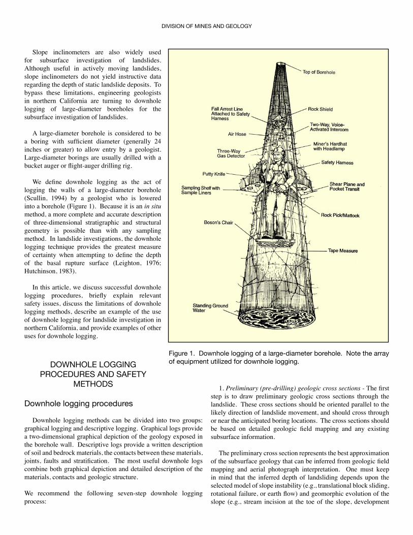
We define downhole logging as the act of logging the walls of a large-diameter borehole (Scullin, 1994) by a geologist who is lowered into a borehole (Figure 1). Because it is an in situ method, a more complete and accurate description of three-dimensional stratigraphic and structural geometry is possible than with any sampling method. In landslide investigations, the downhole logging technique provides the greatest measure of certainty when attempting to define the depth of the basal rupture surface (Leighton, 1976; Hutchinson, 1983).
In this article, we discuss successful downhole logging procedures, briefly explain relevant safety issues, discuss the limitations of downhole logging methods, describe an example of the use of downhole logging for landslide investigation in northern California, and provide examples of other uses for downhole logging.
DOWNHOLE LOGGING PROCEDURES AND SAFETY
METHODS
Downhole logging procedures
Downhole logging methods can be divided into two groups: graphical logging and descriptive logging. Graphical logs provide a two-dimensional graphical depiction of the geology exposed in the borehole wall. Descriptive logs provide a written description of soil and bedrock materials, the contacts between these materials, joints, faults and stratification. The most useful downhole logs combine both graphical depiction and detailed description of the materials, contacts and geologic structure.
We recommend the following seven-step downhole logging process:
1. Preliminary (pre-drilling) geologic cross sections - The first step is to draw preliminary geologic cross sections through the landslide. These cross sections should be oriented parallel to the likely direction of landslide movement, and should cross through or near the anticipated boring locations. The cross sections should be based on detailed geologic field mapping and any existing subsurface information.
The preliminary cross section represents the best approximation of the subsurface geology that can be inferred from geologic field mapping and aerial photograph interpretation. One must keep in mind that the inferred depth of landsliding depends upon the selected model of slope instability (e.g., translational block sliding, rotational failure, or earth flow) and geomorphic evolution of the slope (e.g., stream incision at the toe of the slope, development
Figure 1. Downhole logging of a large-diameter borehole. Note the array of equipment utilized for downhole logging.
ENGINEERING GEOLOGY PRACTICE IN NORTHERN CALIFORNIA
of graben features at the head of the landslide). A reasonable set of working hypotheses is essential to the development of a preliminary cross section. The appropriate depths of the expected geologic features (under one or more hypotheses) should be shown on the cross-section. The locations of large-diameter borings should be chosen to confirm the predicted subsurface geology or to disprove a particular hypothesis regarding that geology.
2. Borehole drilling and cuttings log - The second step is to drill the boring through the identified targets, to the desired depth, and log the cuttings produced by the drilling process. Typically, the boring will be drilled deeper than the anticipated targets, to allow for logging the material below the target features and to allow for accumulation of spoils in the lower portion of the borehole. For the purpose of logging cuttings, bucket augers are superior to flight augers, because the bucket auger retrieves a finite amount of material from a discrete depth with a minimum of mixing. The cuttings log is constructed in a manner similar to that of a small-diameter boring log and should emphasize the lithology or soil types encountered, color, oxidation, weathering, moisture content, and the presence of sheared materials. If gouge is observed in the cuttings, the depth should be noted on the log, and further investigation of potential shear zones should focus on this depth during downhole logging. If a portion of the borehole is inaccessible due to groundwater or caving conditions, the cuttings log may provide the only record of the materials encountered at those depths. The cuttings log can be used to construct a preliminary skeleton log in a large (typically 36 inch by 24 inch) format. This format allows the development of a detailed downhole graphical log at a suitable scale, such as 1 inch equals 2 feet, and provides room for an accompanying written description; this skeleton log can then be modified with details from downhole logging during later steps.
3. Selection of borehole side wall for downhole logging - Third, the geologist should select for logging the vertical plane that bisects the borehole and is oriented parallel to the plane of the cross section. The two vertical lines that form the intersections of this plane with the borehole walls can then be marked in the borehole. Typically, one of these intersection lines will be marked with a 100- to 200-foot long measuring tape that provides depth measurements from the ground surface. These intersection lines should be checked downhole with a compass, because boreholes frequently deviate from a vertical orientation.
4. Side wall cleaning - The fourth step is to clean one side of the borehole between the two intersection lines (the “side wall”). The cleaning process should expose an area that corresponds to 180° of the circumference of the borehole. Usually, the side of the borehole that corresponds to the direction of
view of the cross section is chosen for cleaning. Borehole cleaning is typically accomplished by “hacking” or chipping the borehole surface with the pick end of a weeding tool or mattock. Cleaning the borehole is essential for thorough exposure of critical features and conditions such as shear zones, lithologic contacts and raveling ground. If the cleaning portion of the downhole logging process were done inadequately, the resulting boring logs would be deficient in detail and might omit significant shear zones.
A typical bucket auger will leave the borehole wall smeared with a 1- to 2-inch thick rind of cuttings and disturbed geologic materials. The selection of the proper cleaning methods and tools is essential for the complete exposure of the underlying geology. For unconsolidated sediments, a light-weight weeding tool with a series of fork-like tines provides good results. In rock and well-consolidated deposits, the pick end of a heavy mattock is a better tool. The mattock has a single stout pick that is heavy enough to chip the surface of the borehole and strong enough to withstand pounding against competent geologic materials. When wielded with sufficient force, these tools provide a ripping action that removes the smeared material. A common putty knife is also useful for removing gouge materials to expose the bounding surfaces of a shear zone.
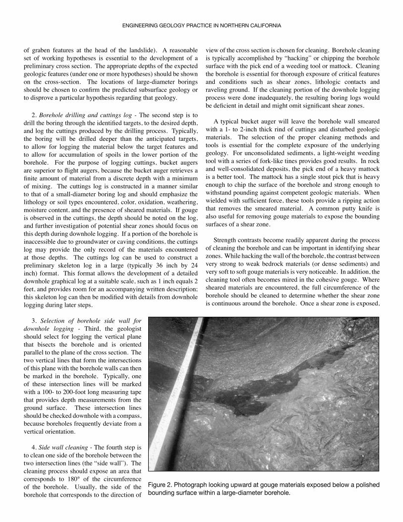
Strength contrasts become readily apparent during the process of cleaning the borehole and can be important in identifying shear zones. While hacking the wall of the borehole, the contrast between very strong to weak bedrock materials (or dense sediments) and very soft to soft gouge materials is very noticeable. In addition, the cleaning tool often becomes mired in the cohesive gouge. Where sheared materials are encountered, the full circumference of the borehole should be cleaned to determine whether the shear zone is continuous around the borehole. Once a shear zone is exposed,
Figure 2. Photograph looking upward at gouge materials exposed below a polished bounding surface within a large-diameter borehole.
DIVISION OF MINES AND GEOLOGY
the gouge materials should be excavated to expose the bounding surfaces (Figure 2). The lower bounding surface is best exposed by hacking from above to remove the gouge, and the upper surface is best exposed by hacking from below.
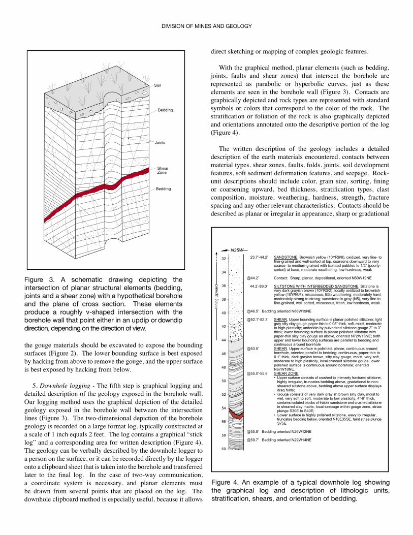
5. Downhole logging - The fifth step is graphical logging and detailed description of the geology exposed in the borehole wall. Our logging method uses the graphical depiction of the detailed geology exposed in the borehole wall between the intersection lines (Figure 3). The two-dimensional depiction of the borehole geology is recorded on a large format log, typically constructed at a scale of 1 inch equals 2 feet. The log contains a graphical “stick log” and a corresponding area for written description (Figure 4). The geology can be verbally described by the downhole logger to a person on the surface, or it can be recorded directly by the logger onto a clipboard sheet that is taken into the borehole and transferred later to the final log. In the case of two-way communication, a coordinate system is necessary, and planar elements must be drawn from several points that are placed on the log. The downhole clipboard method is especially useful, because it allows
direct sketching or mapping of complex geologic features.
With the graphical method, planar elements (such as bedding, joints, faults and shear zones) that intersect the borehole are represented as parabolic or hyperbolic curves, just as these elements are seen in the borehole wall (Figure 3). Contacts are graphically depicted and rock types are represented with standard symbols or colors that correspond to the color of the rock. The stratification or foliation of the rock is also graphically depicted and orientations annotated onto the descriptive portion of the log (Figure 4).
The written description of the geology includes a detailed description of the earth materials encountered, contacts between material types, shear zones, faults, folds, joints, soil development features, soft sediment deformation features, and seepage. Rock-unit descriptions should include color, grain size, sorting, fining or coarsening upward, bed thickness, stratification types, clast composition, moisture, weathering, hardness, strength, fracture spacing and any other relevant characteristics. Contacts should be described as planar or irregular in appearance, sharp or gradational
����
�������
������
���������
�������
Figure 3. A schematic drawing depicting the intersection of planar structural elements (bedding, joints and a shear zone) with a hypothetical borehole and the plane of cross section. These elements produce a roughly v-shaped intersection with the borehole wall that point either in an updip or downdip direction, depending on the direction of view.
�����
��
����������� ����������������������������������������������������������������������������������������������������������������������������������������������������������������������������������������������������������������������������������������������������
������� ��������������������������������������������������������
���������������� �����������������������������������������������������������������������������������������������������������������������������������������������������������������������������������������������������������������������������������������������������������������������������������������������������������������
����������������������������������
������������ �������������������������������������������������������������������������������������������������������������������������������������������������������������������������������������������������������������������������������������������������������������������������������������������������������������������������������������������������������������������������������������������������������������������������������
������ ���������������������������������������������������������������������������������������������������������������������������������������������������������������������������������������������������������������������������������������������������������������������������������������������������������������������������������
������������ ��������������������������������������������������������������������������������
��������������������������������������������������������������������������������������������������������������������������������������
���������������������������������������������������������������������������������������������������������������������������������������������������������������������������������������������������������������������������������������������������������������������������������������
������������������������������������������������������������������������������������������������������������������������������������
����������������������������������
����������������������������������
��
��
��
��
��
��
��
��
��
��
�� � � � � �
��
�
��
� � ��
�� ��
��
��
��
�������
���
���
Figure 4. An example of a typical downhole log showing the graphical log and description of lithologic units, stratification, shears, and orientation of bedding.
ENGINEERING GEOLOGY PRACTICE IN NORTHERN CALIFORNIA
in transition, and depositional, erosional or sheared in origin. In addition, if the contact were sufficiently planar, its orientation should be measured and recorded. Fractures should be described in terms of orientation, filling material, oxidation, and width of open or filled space. A systematic explanation of engineering geologic description can be found in USBR (1998).
A thorough description of shear zones is particularly important, because the interpretation of these shear zones is key to the understanding of the depth and mechanics of landslide deformation, as well as the possible mode of origin. Many shear zones consist of shear gouge bounded by surfaces that are polished and striated; these two elements should be described separately. The pertinent parameters for the bounding surfaces include: surface polishing, degree of striae development (faint, weakly developed, moderately developed, well developed), striae orientation, appearance of surfaces (e.g., planar, irregular, wavy), continuity around the borehole, and orientation. The geologist should describe striae that can be confidently ascribed to a natural origin, rather than those that were created during excavation of
the gouge. The gouge should be described in terms of grain size, color, plasticity, moisture and consistency. Shear gouges typically consist of clay, crushed rock or a cohesive, inhomogeneous mixture of crushed rock and clay. The geologist should also describe any polished surfaces within the gouge materials, especially those that are continuous around the borehole. Any distinct sense of slip indicators, such as offset beds or other piercing points, should be described and the amount and sense of slip should be noted.
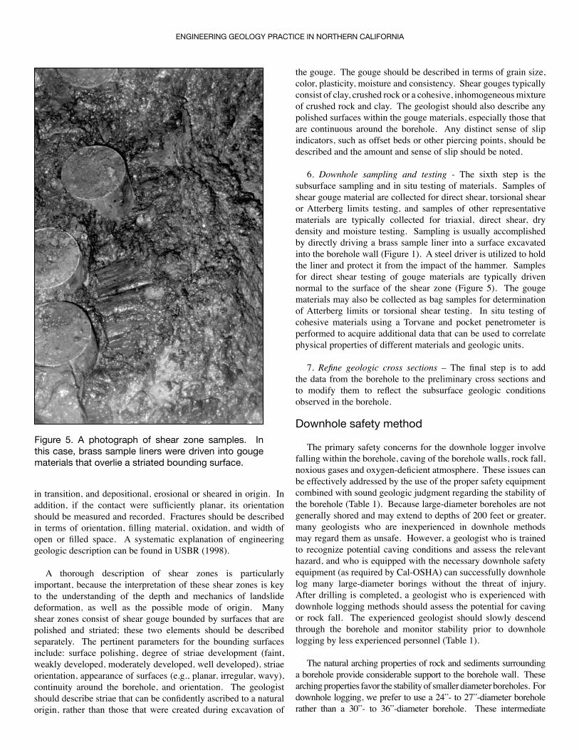
6. Downhole sampling and testing - The sixth step is the subsurface sampling and in situ testing of materials. Samples of shear gouge material are collected for direct shear, torsional shear or Atterberg limits testing, and samples of other representative materials are typically collected for triaxial, direct shear, dry density and moisture testing. Sampling is usually accomplished by directly driving a brass sample liner into a surface excavated into the borehole wall (Figure 1). A steel driver is utilized to hold the liner and protect it from the impact of the hammer. Samples for direct shear testing of gouge materials are typically driven normal to the surface of the shear zone (Figure 5). The gouge materials may also be collected as bag samples for determination of Atterberg limits or torsional shear testing. In situ testing of cohesive materials using a Torvane and pocket penetrometer is performed to acquire additional data that can be used to correlate physical properties of different materials and geologic units.
7. Refine geologic cross sections – The final step is to add the data from the borehole to the preliminary cross sections and to modify them to reflect the subsurface geologic conditions observed in the borehole.
Downhole safety method
The primary safety concerns for the downhole logger involve falling within the borehole, caving of the borehole walls, rock fall, noxious gases and oxygen-deficient atmosphere. These issues can be effectively addressed by the use of the proper safety equipment combined with sound geologic judgment regarding the stability of the borehole (Table 1). Because large-diameter boreholes are not generally shored and may extend to depths of 200 feet or greater, many geologists who are inexperienced in downhole methods may regard them as unsafe. However, a geologist who is trained to recognize potential caving conditions and assess the relevant hazard, and who is equipped with the necessary downhole safety equipment (as required by Cal-OSHA) can successfully downhole log many large-diameter borings without the threat of injury. After drilling is completed, a geologist who is experienced with downhole logging methods should assess the potential for caving or rock fall. The experienced geologist should slowly descend through the borehole and monitor stability prior to downhole logging by less experienced personnel (Table 1).
The natural arching properties of rock and sediments surrounding a borehole provide considerable support to the borehole wall. These arching properties favor the stability of smaller diameter boreholes. For downhole logging, we prefer to use a 24”- to 27”-diameter borehole rather than a 30”- to 36”-diameter borehole. These intermediate
Figure 5. A photograph of shear zone samples. In this case, brass sample liners were driven into gouge materials that overlie a striated bounding surface.
diameter boreholes provide both optimum stability and adequate room for the geologist to enter and work.
LIMITATIONS OF DOWNHOLE LOGGING
Although downhole logging of large-diameter boreholes has proven very effective for subsurface investigation of landslides, certain geological conditions may severely complicate or prevent the use of downhole logging. Downhole logging is very difficult or impossible where running or fast raveling ground is encountered, where concentrations of noxious gases are high, or where standing groundwater is very shallow. To some extent, all of these problems can be addressed with the use of specific drilling and downhole logging techniques (Table 2). However, in severe cases these problems may make downhole logging impractical.
CASE STUDY
In 1995, we conducted an investigation of an active landslide that threatened a winery building located on a hillside flanking the Carneros Valley, west of the town of Napa, California. Our review of historical aerial photographs indicated that the southeast flank of the hill was underlain by a well-defined ancient landslide mass, and the active landslide appeared to represent the reactivation of a sizable portion of this mass (Landslide A in Figure 7). A more subtly-defined ancient landslide mass was identified west of Landslide A.
The local stratigraphy includes Quaternary alluvium and terrace deposits, the Pleistocene Huichica Formation, and the Miocene Neroly Sandstone. The Huichica Formation consists
DIVISION OF MINES AND GEOLOGY
POTENTIAL HAZARD MITIGATION MEASURE
Sloughing of soil and loose sediments near the surface
• Loose earth materials should be removed from the perimeter of the borehole.• The entrance of the borehole should be protected with a short length (4 or 5 feet) of casing that extends 1 to 2 feet above the ground surface.
Caving and spalling of the borehole wall
• As the experienced geologist slowly descends through the borehole, the potential for caving or raveling ground is assessed and the presence of sheared material and free water is monitored.• If caving is confined to a specific interval within the borehole, that portion of the borehole may be reamed to a larger diameter and stabilized by inserting steel casing to seal off the caving interval.• If caving is severe, downhole logging may not be feasible below the caving interval.
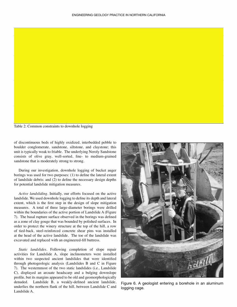
Rockfall • While descending through the borehole, the geologist checks for unstable blocks, especially those that rest along discontinuities that are inclined into the borehole. • Remove unstable blocks before proceeding deeper into the borehole. • Deflect rockfall by using a rock shield mounted above the logging platform (boson’s chair, Figure 1).• Use an aluminum logging cage (Figure 6). Although the logging cage provides the best protection against rockfall and caving hazards, it should not be used as a means of entering a caving borehole.
Falling within the borehole • The logger is lowered into the borehole via a steel cable connected to a power winch.• If the logger slips off the platform, he or she is prevented from falling by a separate fall arrest line that is connected to a body harness.
Noxious gases and oxygen-deficient atmosphere
• A three-way gas detector measures levels of oxygen, hydrogen sulfide, and explosive gases (i.e., methane) in the logger’s breathing space (Figure 1).• The borehole atmosphere is also monitored prior to downhole logging. • The borehole is continuously ventilated with an air blower and flexible plastic hose during downhole logging.
Poor lighting • The logger typically clips a miner’s headlamp to his or her hardhat. The headlamp is powered by a belt-mounted wet cell battery.
Difficulty communicating with the downhole logger
• The logger should communicate with the rig operator and others at the surface via a voice-activated, two-way communication system (Figure 1).
Table 1: Downhole safety methods
ENGINEERING GEOLOGY PRACTICE IN NORTHERN CALIFORNIA
of discontinuous beds of highly oxidized, interbedded pebble to boulder conglomerate, sandstone, siltstone, and claystone; this unit is typically weak to friable. The underlying Neroly Sandstone consists of olive gray, well-sorted, fine- to medium-grained sandstone that is moderately strong to strong.
During our investigation, downhole logging of bucket auger borings was used for two purposes: (1) to define the lateral extent of landslide debris; and (2) to define the necessary design depths for potential landslide mitigation measures.
Active landsliding. Initially, our efforts focused on the active landslide. We used downhole logging to define its depth and lateral extent, which is the first step in the design of slope mitigation measures. A total of three large-diameter borings were drilled within the boundaries of the active portion of Landslide A (Figure 7). The basal rupture surface observed in the borings was defined as a zone of clay gouge that was bounded by polished surfaces. In order to protect the winery structure at the top of the hill, a row of tied-back, steel-reinforced concrete shear pins was installed at the head of the active landslide. The toe of the landslide was excavated and replaced with an engineered-fill buttress.
Static landslides. Following completion of slope repair activities for Landslide A, slope inclinometers were installed within two suspected ancient landslides that were identified through photogeologic analysis (Landslides B and C in Figure 7). The westernmost of the two static landslides (i.e., Landslide C), displayed an arcuate headscarp and a bulging downslope profile, but its margins appeared to be old and geomorphologically denuded. Landslide B, a weakly-defined ancient landslide, underlies the northern flank of the hill, between Landslide C and Landslide A.
CONSTRAINT MITIGATIVE PROCEDURE
Running sands or fast-raveling unconsolidated sediments
• Attempt to stabilize caving interval with steel casing.• If severe caving occurs before casing can be inserted, attempt to drill at an alternate location or utilize small-diameter coring methods.
Shallow groundwater (Vadose zone)
• Slow seepage on the borehole walls does not present a serious problem unless accompanied by caving.• The boring can be drilled past the intended depth to allow the water to collect below the intended interval of interest.
Shallow groundwater table (Saturated zone)
• Use a submersible pump to temporarily lower the groundwater level in the borehole. This method is most effective where the borehole is drilled in moderately strong to very strong rock that has low permeability (primarily fracture permeability) and widely-spaced fractures of narrow width.
Exploration depth • The depth of exploration is limited by groundwater conditions, borehole stability, and the depth range of the drilling rigs; most bucket auger rigs cannot drill deeper than 200 feet.
Table 2: Common constraints to downhole logging
Figure 6. A geologist entering a borehole in an aluminum logging cage.
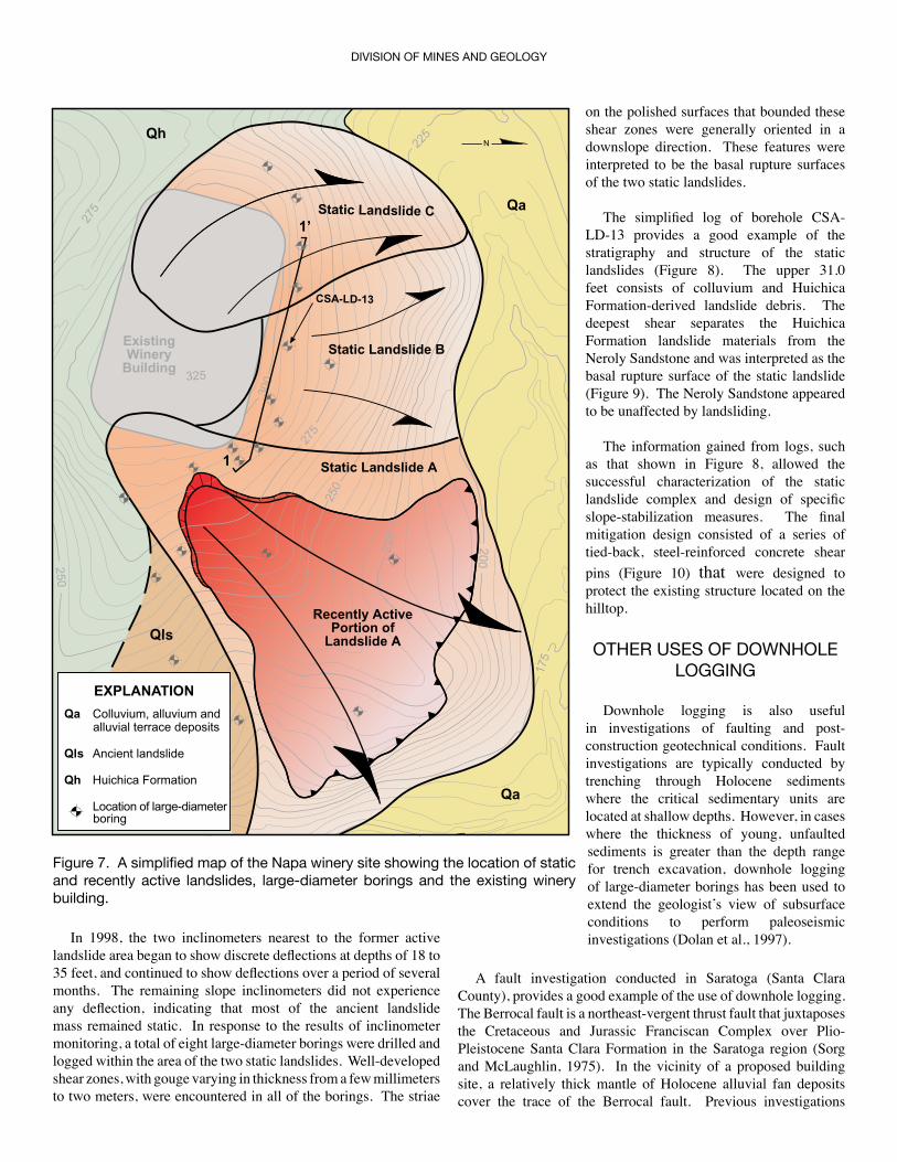
In 1998, the two inclinometers nearest to the former active landslide area began to show discrete deflections at depths of 18 to 35 feet, and continued to show deflections over a period of several months. The remaining slope inclinometers did not experience any deflection, indicating that most of the ancient landslide mass remained static. In response to the results of inclinometer monitoring, a total of eight large-diameter borings were drilled and logged within the area of the two static landslides. Well-developed shear zones, with gouge varying in thickness from a few millimeters to two meters, were encountered in all of the borings. The striae
DIVISION OF MINES AND GEOLOGY
� ���
����
���
���
���
���
���
���
���
������
���
���
��
�
��
���
������ ��������� �
������ ��������� �
������ ��������� �
�������� ������������� ��
��������� �
��
��
���������
�
�����������
�� ���������� �������� ����������� ������� ��������
��� ������� ���������
�� �������� ���������
�������� �� ��������������������
��������������
�����������
Figure 7. A simplified map of the Napa winery site showing the location of static and recently active landslides, large-diameter borings and the existing winery building.
on the polished surfaces that bounded these shear zones were generally oriented in a downslope direction. These features were interpreted to be the basal rupture surfaces of the two static landslides.
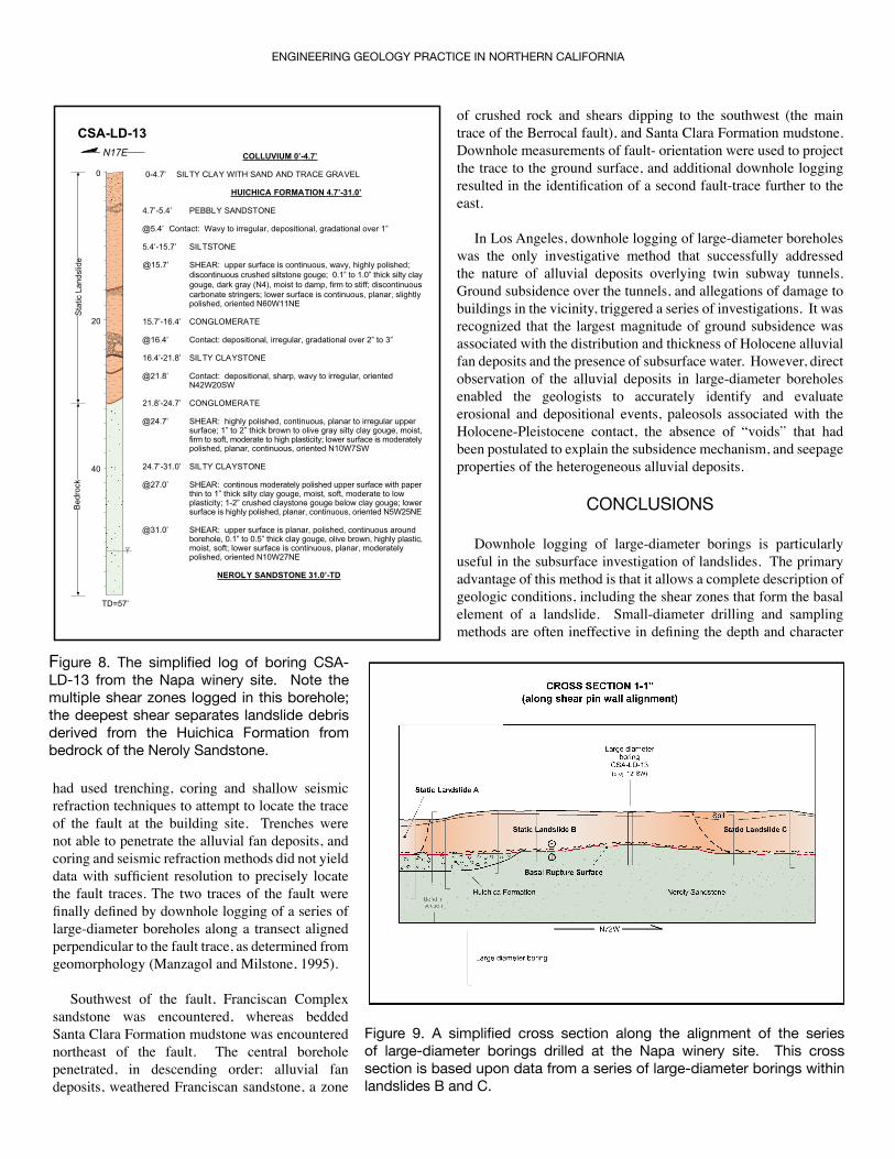
The simplified log of borehole CSA-LD-13 provides a good example of the stratigraphy and structure of the static landslides (Figure 8). The upper 31.0 feet consists of colluvium and Huichica Formation-derived landslide debris. The deepest shear separates the Huichica Formation landslide materials from the Neroly Sandstone and was interpreted as the basal rupture surface of the static landslide (Figure 9). The Neroly Sandstone appeared to be unaffected by landsliding.
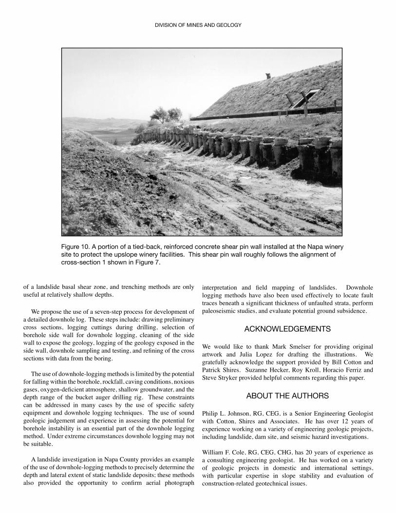
The information gained from logs, such as that shown in Figure 8, allowed the successful characterization of the static landslide complex and design of specific slope-stabilization measures. The final mitigation design consisted of a series of tied-back, steel-reinforced concrete shear pins (Figure 10) that were designed to protect the existing structure located on the hilltop.
OTHER USES OF DOWNHOLE LOGGING
Downhole logging is also useful in investigations of faulting and post-construction geotechnical conditions. Fault investigations are typically conducted by trenching through Holocene sediments where the critical sedimentary units are located at shallow depths. However, in cases where the thickness of young, unfaulted sediments is greater than the depth range for trench excavation, downhole logging of large-diameter borings has been used to extend the geologistʼs view of subsurface conditions to perform paleoseismic investigations (Dolan et al., 1997).
A fault investigation conducted in Saratoga (Santa Clara County), provides a good example of the use of downhole logging. The Berrocal fault is a northeast-vergent thrust fault that juxtaposes the Cretaceous and Jurassic Franciscan Complex over Plio-Pleistocene Santa Clara Formation in the Saratoga region (Sorg and McLaughlin, 1975). In the vicinity of a proposed building site, a relatively thick mantle of Holocene alluvial fan deposits cover the trace of the Berrocal fault. Previous investigations
ENGINEERING GEOLOGY PRACTICE IN NORTHERN CALIFORNIA
had used trenching, coring and shallow seismic refraction techniques to attempt to locate the trace of the fault at the building site. Trenches were not able to penetrate the alluvial fan deposits, and coring and seismic refraction methods did not yield data with sufficient resolution to precisely locate the fault traces. The two traces of the fault were finally defined by downhole logging of a series of large-diameter boreholes along a transect aligned perpendicular to the fault trace, as determined from geomorphology (Manzagol and Milstone, 1995).
Southwest of the fault, Franciscan Complex sandstone was encountered, whereas bedded Santa Clara Formation mudstone was encountered northeast of the fault. The central borehole penetrated, in descending order: alluvial fan deposits, weathered Franciscan sandstone, a zone
of crushed rock and shears dipping to the southwest (the main trace of the Berrocal fault), and Santa Clara Formation mudstone. Downhole measurements of fault- orientation were used to project the trace to the ground surface, and additional downhole logging resulted in the identification of a second fault-trace further to the east.
In Los Angeles, downhole logging of large-diameter boreholes was the only investigative method that successfully addressed the nature of alluvial deposits overlying twin subway tunnels. Ground subsidence over the tunnels, and allegations of damage to buildings in the vicinity, triggered a series of investigations. It was recognized that the largest magnitude of ground subsidence was associated with the distribution and thickness of Holocene alluvial fan deposits and the presence of subsurface water. However, direct observation of the alluvial deposits in large-diameter boreholes enabled the geologists to accurately identify and evaluate erosional and depositional events, paleosols associated with the Holocene-Pleistocene contact, the absence of “voids” that had been postulated to explain the subsidence mechanism, and seepage properties of the heterogeneous alluvial deposits.
CONCLUSIONS
Downhole logging of large-diameter borings is particularly useful in the subsurface investigation of landslides. The primary advantage of this method is that it allows a complete description of geologic conditions, including the shear zones that form the basal element of a landslide. Small-diameter drilling and sampling methods are often ineffective in defining the depth and character
�������������� �����������������
������ �������������������������������������
��� �����������������������������
��������� ����������������
������ ��������������������������������������������������������������
���������� ���������
������ �����������������������������������������������������������������������������������������������������������������������������������������������������������������������������������������������������������������������������������������������������������������������������������������������
����������� ������������
������ �����������������������������������������������������������
����������� ���������������
������ ������������������������������������������������������������������
����������� ������������
������ ������������������������������������������������������������������������������������������������������������������������������������������������������������������������������������������������������������������������������������������������������
����������� ���������������
������ �������������������������������������������������������������������������������������������������������������������������������������������������������������������������������������������������������������������������������������������������������������
������ ������������������������������������������������������������������������������������������������������������������������������������������������������������������������������������������������������������������������
�����������������������������
������
�
��
��
���
�����
����
����
���
����
Figure 8. The simplified log of boring CSA-LD-13 from the Napa winery site. Note the multiple shear zones logged in this borehole; the deepest shear separates landslide debris derived from the Huichica Formation from bedrock of the Neroly Sandstone.
� ��
����� ������� ���������� ����� ��� ���� ����������
����� ��������������
��������������� ��� ���
����� �������� ������
���� ���������
����
������ ����������������� ���������
����
������ ��������� �
������ ��������� �
����� ������� �������
������ ��������� �
Figure 9. A simplified cross section along the alignment of the series of large-diameter borings drilled at the Napa winery site. This cross section is based upon data from a series of large-diameter borings within landslides B and C.
of a landslide basal shear zone, and trenching methods are only useful at relatively shallow depths.
We propose the use of a seven-step process for development of a detailed downhole log. These steps include: drawing preliminary cross sections, logging cuttings during drilling, selection of borehole side wall for downhole logging, cleaning of the side wall to expose the geology, logging of the geology exposed in the side wall, downhole sampling and testing, and refining of the cross sections with data from the boring.
The use of downhole-logging methods is limited by the potential for falling within the borehole, rockfall, caving conditions, noxious gases, oxygen-deficient atmosphere, shallow groundwater, and the depth range of the bucket auger drilling rig. These constraints can be addressed in many cases by the use of specific safety equipment and downhole logging techniques. The use of sound geologic judgement and experience in assessing the potential for borehole instability is an essential part of the downhole logging method. Under extreme circumstances downhole logging may not be suitable.
A landslide investigation in Napa County provides an example of the use of downhole-logging methods to precisely determine the depth and lateral extent of static landslide deposits; these methods also provided the opportunity to confirm aerial photograph
DIVISION OF MINES AND GEOLOGY
Figure 10. A portion of a tied-back, reinforced concrete shear pin wall installed at the Napa winery site to protect the upslope winery facilities. This shear pin wall roughly follows the alignment of cross-section 1 shown in Figure 7.
interpretation and field mapping of landslides. Downhole logging methods have also been used effectively to locate fault traces beneath a significant thickness of unfaulted strata, perform paleoseismic studies, and evaluate potential ground subsidence.
ACKNOWLEDGEMENTS
We would like to thank Mark Smelser for providing original artwork and Julia Lopez for drafting the illustrations. We gratefully acknowledge the support provided by Bill Cotton and Patrick Shires. Suzanne Hecker, Roy Kroll, Horacio Ferriz and Steve Stryker provided helpful comments regarding this paper.
ABOUT THE AUTHORS
Philip L. Johnson, RG, CEG, is a Senior Engineering Geologist with Cotton, Shires and Associates. He has over 12 years of experience working on a variety of engineering geologic projects, including landslide, dam site, and seismic hazard investigations.
William F. Cole, RG, CEG, CHG, has 20 years of experience as a consulting engineering geologist. He has worked on a variety of geologic projects in domestic and international settings, with particular expertise in slope stability and evaluation of construction-related geotechnical issues.
ENGINEERING GEOLOGY PRACTICE IN NORTHERN CALIFORNIA
REFERENCES
Dolan, J. F., Sieh, K., Rockwell, T. K., Guptill, P., and Miller, G., 1997, Active tectonics, paleoseismology and seismic hazards of the Hollywood fault, Northern Los Angeles basin, California: Geological Society of America Bulletin, v. 109, p.1595-1616.
Hutchinson, J. N., 1983, Methods of locating slip surfaces in landslides: Bulletin of the Association of Engineering Geologists, v. XX, no. 3, p. 235-252.
Leighton, F.B., 1976, Geomorphology and engineering control of landslides: in Coates, D. R. (ed.), Geomorphology and engineering, proceedings of 7th geomorphology symposium, George Allen & Unwin, London, p. 273-287.
Manzagol, T.J. and Milstone, B.S., 1995, A geologic and geotechnical investigation, Lot 13 Teerlink Subdivision Tract 6781, Heber Way, Saratoga, California: Consultantʼs report to Mr. Steve Sheng.
Scullin, C. M., 1994, Subsurface exploration using bucket auger borings and down-hole geologic inspection: Bulletin of the Association of Engineering Geologists, v. XXXI, p. 91-105.
Sorg, D.H. and McLaughlin, R.J., 1975, Geologic map of the Sargent-Berrocal fault zone between Los Gatos and Los Altos Hills, Santa Clara County, California: U.S. Geological Survey Miscellaneous Field Investigations, MF-643.
USBR, 1998, Engineering geology field manual, second edition: United States Department of the Interior, Bureau of Reclamation, Denver, Colorado, 496 p.