the triga reactor facility at the armed forces ... · the reactor is general atomic's triga...
TRANSCRIPT

AD-A275 643 -
1i111111lim1 January 1994
AFRRI94-1 TECHNICAL REPORT
The TRIGA Reactor Facilityat the Armed ForcesRadiobiology Research DTE CInstitute: A Simplified FEB 1
Technical Description
S
Mark L. Moore 94-05016
AFRRI TR94-1 Cleared for Public Release; Distribution Unlimited
Armed Forces Radiobiology Research Institute8901 Wisconsin AvenueBethesda, Maryland 20889-5603
94 2 15 002
REPORT DOCUMENTATION PAGE For AM op070-018
APfic rowiung burden for insit coisectio of inforainston is esanwmaed to iners I four am essonsea. inou"dfl thO troe for sweisming notir uoarsrs searcnw'g existing data sowrceswwlr~l anieMsrnasn~nig we1 dasnesiwded, and connf~flsmag ants reviewtsfig me cauOiat.n of fiformans Swift "osfinoten resfO llg oini burdo caisnaff or env otheor $sea 't ~f '
aftdbWen of -ntwmai~. aicfulsing suOspioflw for reduding thifs buriln. to WOO Patge OdWm*dflor Solacs Directorate for informaision Owaassenae and fassona ¶ i215 .jaflrsoeDavis Hign wsi, Suit* 204. Arlington., VA 22202-4302. WWt nse Olt-toW. of Moignseemmw and SLdi PaOWWeOW fledusfictiiiss a 0704410111 Wean ren. OC 20M3
1.- AGENCY USE ONLY (Leave blank) 2. REPORT DATE 3. REPORT TYPE AND DATES COVEREDI January 1994 Technical Report
4. TITLE AND SUBTITLE 5. FUNDING NUMBERSThe TRIGA Reactor Facility at the Armed Forces P:QXRadiobiology Research Institute: A Simplified Technical P: QXDescription
6. AUTHO0R(S)
Moore, Mark L.
7. PERFORMING ORGANIZATION NAMEf 5) AND AODRESS(ES) B. PERFORMING ORGANIZATION
Armed Forces Radiobiology Research Institute REPORT NUMBER8901 Wisconsin Avenue TR94-1Bethesda, Md. 20889-5603
9. SPONSORING/MONITORING AGENCY NAMEfS1 AND ADDRESS(ES) 10. SPONSORING/ MONITORINGAGENCY REPORT NUMBER
Uniformed Services University of the Health Sciences4301 Jones Bridge RoadBethesda, Md. 20814-4799
11. SUPPLEMENTARY NOTES
This publication is a revision of the previously published AFRRI TechnicalReport 86-1.
1 2s. DISTRIBUTIOI4/AVAILABIU1TY STATEMENT 12b. DISTRIBUTION CODE
Approved for public release; distribution unlimited.
13. ABSTRACT (Mazimum~fl 200 Wordt)
This publication provides a simplified technical description of the TRIGAresearch reactor at AFRRI. Topics covered include general prin~ciples of reactoroperation and a description of the TRIGA reactor and its unique features.
14. SUBJECT TERMS 15. NUMBER OF PAGES22
16. PRICE CODE
17. SECURITY CLASSIFICATION IS. SECURMITY CLASSIFICATION 19. SECUR17Y CLASSIFICATION 20. LIMITATION OFOF REPORT OF THIS PAGE OF ABSTRACT ABSTRACT
UNCLASSIFIED UNCLASSIFIED UNCLASSIFIED UL
14SN 7S4041 -290-SW S tandard Form 296 (Rev 2 891

SICUPIlY CLASWACAMIOI OP ThIS PACECLASSIFIED SY:
011CLASSIFY ON:
SEOJY a.SIFCAMlN 21 THIS PAGE-
AFRRI Technical Report 94-1
THE TRIGA REACTOR FACILITY AT THEARMED FORCES RADIOBIOLOGY RESEARCH INSTITUTE
A SIMPLIFIED TECHNICAL DESCRIPTION
Mark L. Moore
Accesion For
NTIS CRA&I
DTIC TAB 0Unannounced 0JiiSt if Cdt•
By
Distributo01o I
January 1994 Avadblty Codes
Avdf( rld (orDIst SPecial
Radiation Sources Department
ARMED FORCES RADIOBIOLOGY RESEARCH INSTITUTE8901 Wisconsin Avenue
Bethesda, Maryland 20889-5603
Cleared for Public Release; Distribution Unlimited

Contents
Introduction ............................... 1Mission .............................. 1Reactor .. . . .. . . . . .. . .. . .. . .. . . . .. 1
General Principles of Reactor Operation ............ 3
Fission Process .......................... 3Control of the Nuclear Reaction ................ 4
Description of the TRIGA Reactor ................. 6
Reactor Core ........................... 6Reactor Fuel Element ..................... 8Control Rods ........................... 9Neutron Source .......................... 11
Instrumentation .......................... 11
Cooling Systems ......................... 11Lead Shield Doors ........................ 12
Unique Features of the TRIGA Reactor .............. 12Modes of Operation ....................... 12Visible Cherenkov Radiation .................. 12
Exposure Facilities ........................ 12
Summary .................................. 15

Introduction
Mission
The Armed Forces Radiobiology Research Institute (AFRRI) conducts research in thefield of radiobiology and related matters that are essential to the operational and medicalsupport of the Department of Defense. AFRRI is staffed by members of the three militaryservices and by civilian personnel. In support of its mission, AFRRI operates a researchreactor.
Reactor
The reactor, a medium-sized 1.0-megawatt research reactor that generates neutronsand gamma rays for radiation experiments (see figure 1), is a primary radiation sourceat AFRRI. The reactor is General Atomic's TRIGA reactor; TRIGA is an acronym fortraining, research, isotope, General Atomic. The TRIGA reactor is designed to beinherently safe, i.e., the reactor's design is such that there is no possibility of an accidentthat can produce an unsafe condition for the staff or the general public. Since the late1950s, more than 70 TRIGA reactors have been used worldwide for a variety ofapplications with no accidents. The TRIGA reactor at AFRRI has been operating since1962.
PNEUMATIC TUBE SYSTEM
CONTROL ROD DRIVES
REACTOR TANK
REACTOR CORE'• •" EXPOSURE RlOOM 2
EXPOSURE ROOM I LEAD SHIELDING DOORS
PLUG DOOR
Figure 1. Cutaway view of AFRRI TRIGA reactor.

General Principles of Reactor Operation
Fission Process
At the heart of any reactor is the fission process. Certain elements are likely to undergofission when they absorb a neutron. One such element is uranium-235. Uranium-235 isour nuclear fuel, and it is packed into fuel elements in the reactor core. Whenuranium-235 absorbs a neutron, it becomes unstable, breaks up into two or morefragments, and releases a large amount of energy. These fragments are the nuclei ofsmaller elements and are called fission products. Most of the energy released duringfission is manifested in the form of kinetic energy (speed) given to the fission products.When the fission products collide with their surrounding atoms, heat is produced. Inaddition to the fission products, several extra neutrons and gamma rays are released.Some of the extra neutrons go on to be absorbed by other uranium-235 nuclei, thusproducing the nuclear fission chain reaction shown in figure 2.
NEUTRON FRaSa.
FRAMN FRAGAEND
NEUTRON NEUTRONON
2S FISSIONIO N ETO
FISSION FISO
2 3 *6U FRAGMENFRAGMENT NEUTRN
Figure 2. Nuclear fission chain re2,3tion (gamma rays = U).
3

The heat produced in the fission chain reaction is allowed to dissipate in a large pool ofwater. The TRIGA reactor differs from a reactor in a commercial nuclear power plant inthat the product of interest is the radiation produced; the heat is considered a wasteproduct. For a reactor in a commercial nuclear power plant, the heat is the product ofinterest.
An important factor that influences the fission process is the kinetic energy of theneutrons absorbed by uranium-235 nuclei. Uranium-235 nuclei absorb neutrons whenthe neutrons are travelling relatively slowly (0.025 electron volts or 2,200 meters persecond). These slow neutrons are called thermal neutrons. Because neutrons bom fromfission are usually travelling fast, they must be slowed down to the appropriate speed.This slowing process is called neutron moderation. Neutron moderation occurs whenneutrons collide with light atoms such as hydrogen and lose energy by elastic scatter,similar to how pool balls slow down when they collide.
Most of the fission fragments are radioactive and decay to stable (nonradioactive) nucleiby emitting any combination of alpha particles, beta particles, gamma rays, andneutrons. The neutrons emitted by fission products are called delayed neutrons.Although only about 0.7% of all neutrons are delayed neutrons, they are an importantcomponent in controlling the nuclear fission chain reaction.
Control of the Nuclear Reaction
The nuclear fission chain reaction can grow indefinitely. A reactor is limited only by howmuch heat can be removed from the reactor core. To limit the fission rate and thus theheat production rate, neutron-absorbing materials are inserted into the reactor core. Theneutron absorbers, called control rods, absorb neutrons in the reactor core, making theneutrons unavailable for the fission process. If enough neutrons are absorbed, there willnot be enough neutrons available to sustain the fission chain reaction, and the reactorwill reduce its power level.
The neutron absorber used in the TRIGA reactor core is boron carbide. The isotopeboron-10 readily absorbs neutrons. The boron carbide is packed into the controlrods as shown in figure 3. The reactor uses four of these control rods to control itspower level.
4

THREADED END CAP -- _
AIR-FILLED 7 IN.EXTENSION SECTION --,J
BORON CARBIDEPoison Section) 1.4S-DIA.
15 IN.
STAINLESS STEEL SHELL1.1251N 0D Tb.ngV 020WT
38.38 IN.t
MAGNAFORM 0 / 7 ON W.
ZIRCONIUM ROD. S~14.75 IN.FUEL FOLLOWER -- 7-
SECTION
Figure 3. Reactor control rod.
5

When control rods are pulled out of the reactor, the reactor power increases. Thecontrolled increase in power is due to the effects of the delayed neutrons discussed inthe previous section. If all neutrons were born at the instant of fission, reactors wouldinstantaneously increase in power and be difficult, if not impossible, to control. Ascontrol rods are inserted into the reactor, the power level decreases.
The generation of heat during the fission chain reaction affects the reactor core's abilityto moderate (slow down) neutrons and decreases the density of the uranium-235 fuelatoms and other materials in the core. These effects can be harnessed to help control areactor. Through judicious selection of materials for fuel elements and fuel elementdesign, these passive factors in reactor control can make the reactor inherently safe.
Description of the TRIGA Reactor
Reactor Core
To produce a controlled, self-sustaining fission chain reaction, the fuel elementscontaining uranium fuel and the neutron-absorbing control rods must be arranged in aspecial way; this arrangement of fuel elements and control rods is called the reactorcore. In addition to the fuel elements and control rods, the reactor core also contains aneutron source. Figure 4 shows the reactor core.
ROD DRIVEMECHANISM
ION CHAMBER CONTROL. •OD
PULM OO FISSION DETECTOR
CORE SHROUD• •FUEL ELEMENTS
Figure 4. Reactor core.
6
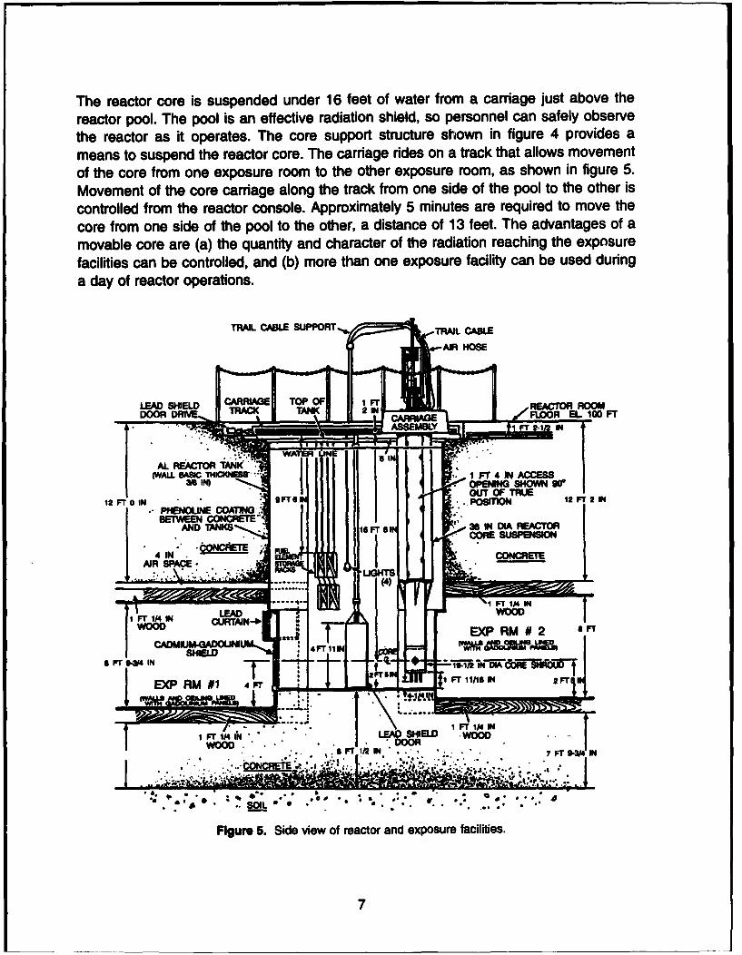
The reactor core is suspended under 16 feet of water from a carriage just above the
reactor pool. The pool is an effective radiation shield, so personnel can safely observe
the reactor as it operates. The core support structure shown in figure 4 provides a
means to suspend the reactor core. The carriage rdes on a track that allows movement
of the core from one exposure room to the other exposure room, as shown in figure 5.
Movement of the core carriage along the track from one side of the pool to the other is
controlled from the reactor console. Approximately 5 minutes are required to move the
core from one side of the pool to the other, a distance of 13 feet. The advantages of a
movable core are (a) the quantity and character of the radiation reaching the exposure
facilities can be controlled, and (b) more than one exposure facility can be used during
a day of reactor operations.
TRAIL CAL SUPPORT,,.TRICAL
LEAD SHIELD 1,, D TO OEAO I
DOR RVEWRCK TAK 2 N ;gDL
0-SE FT " N" .PSTO 2- IN R
I~~~~~~ .. INEJECAIN,••ALBEATORE TA N"K NDI ECO
(ALBSCTHICIINSAN :,.. ,. I Fr4I ACS
38IN ur 5.EIN SideN v9wo0eatradexouefaiiis
12 FIP TION 124F2BETWEE4N CI TEO
AND HisM 16 Fr $IN i T111 IN DI FATO
4 IN FT ./ CO LDD•L F/NCRT
• . . ~~ ~~. ..... .,:.; Jr}. . " . •' " " " ,
.. '.~~~~~ ~ ~~ N ,.",.. : " , ,,._",....,".,
Fiur Fr Side INe ofratoEnAepsrefcliis
WOOD URTAN-17

Reactor Fuel Element
The TRIGA reactor fuel element (figure 6) is designed to capitalize on the inherentcharacteristics of the fuel to provide safe nuclear reactor control. The fuel element ismade of uranium zirconium-hydride (UZrH) metal. The hydrogen in the UZrH metalserves as the primary moderator of neutrons. As the fission chain reaction makes thefuel element hotter, the hydrogen atoms vibrate at increasingly higher frequencies, andthus move rapidly within the metal structure of the UZrH. When a neutron strikes theagitated hydrogen atom, instead of slowing down, it actually speeds up and is unable to
STAINLESS STEELTOP END- FIXTURE
" STAINLESSTRIP LUTE
GRAPHITE
CLADININ. B URNABLEPOISON
WAFER
STAINLESS T R-1IMUM-ZIRCOMIUMS HYDRIDE &.S WT
STEELE URA=MVI LESS THANCLADDING TUBE 20% TTHICKNESS ENRICHMENT
0.021 N.
"2.31 IN.
0.18 IN.ZIRCONIUMEOD
Is IN. RI
I1A3 IN.
1.47 IN.
~- 015 IN. BURNABLEPOISON
0 - SAMARIUM-ALUMINUMWAFER
STAINLESS STEELTBOTTOM END- 346 IN GRAPHITEFIXTURE
ASSEMBLED DISASSEMBLED
Flgeire 6. Reactor fuel element.
8

cause fission. This effect is called the zirconium-hydride disadvantage factor and has anextremely strong influence over controlling the reactor.The zirconium-hydridedisadvantage factor makes the TRIGA reactor inherently safe.
Specific design features of the TRIGA reactor fuel element are:
* 0.02-inch-thick stainless steel cladding,
* 0.18-inch-diameter solid zirconium rod in the center of the fuel element to ensurestructural integrity,
* 0.015-inch-thick samarium wafer at each end of the fuel element (a samariumwafer is a neutron absorber that helps make the neutron flux uniform in the axialdirection and thus extends fuel life), and
* 3.44-inch-long graphite plugs at each end of the fuel element to reflect neutronsback into the fuel element.
The TRIGA reactor can accommodate 4 control rods and up to 87 fuel elements in thereactor core.
Control Rods
Control rods are used to control the rate of the fission chain reaction. Figure 3 shows astandard control rod used in the reactor core. Some of the neutrons in the core that passinto the boron carbide portion of a control rod are absorbed by the boron atoms. Thisreduces the number of neutrons available for fission in the fuel elements, so the fissionrate is reduced. Rod drives that are operated from the control console move the controlrods into or out of the core. The amount of a control rod in the core regulates the fissionrate. A greater length of a control rod in the core results in a greater number of absorbedneutrons and a lower fission rate. If neutrons are being absorbed at a greater rate thanthey are being produced, the fission rate decreases, and the production of power andradiation ends. If neutrons are being produced at a faster rate than they are beingabsorbed, the fission rate, power level, and corresponding radiation increase.Withdrawing just enough of the control rods to match the neutron absorption rate withthe neutron proauction rate achieves a steady-state power level.
9

There are four control rods in the core of the reactor. One control rod is placed in thecenter position-the A ring-and is called the transient rod (figure 7). The remainingthree control rods are called standard control rods and can be one of the following types:aluminum followed, air followed, or fuel followed. When the neutron absorber section iswithdrawn from the core, a section of aluminum, air, or fuel follows in its place. Thesecontrol rods are placed evenly in the D ring (fourth ring) of the reactor core. The controlrods in the fourth ring are called the safe rod, shim rod, and regulating rod. Using thereactor control console, the operator can drive these rods slowly up and down. Theoperator can also "scramu the rods, allowing them to drop by means of gravity back intothe reactor core.
The transient rod can be driven up and down in the same manner as the other controlrods. In addition, the transient rod can be rapidly ejected out of the core by means ofcompressed air. A stopping anvil is positioned above the transient rod to limit the lengthof the transient rod ejected from the core. Application of compressed air lifts thetransient rod from the core until it hits the shock-absorbing anvil. The transient rod canonly be rapidly ejected from the core when the reactor is in the pulse or square wavemode. When the reactor is in the pulse mode it is ready for a brief high-powerexcursion-a sudden dramatic increase in power. In the pulse mode, all control rodsscram shortly after the transient rod is ejected from the core. The time to scram is set by
183/4' DIAMETER91 1 '/' HOLES
SAFE ROD • TRANSIENT ROD
L0CTN ••1LOCATION00
000000 Al 00 1 REGULATING ROD0 0 0 LOCATIONC 0 )0 NEUTRON
O O o SOURCE
LOCATIONF 0
0 /," HOLES FOR IN-COREEXPERIMENTS
Figure 7. Overhead view of reactor core (upper grid plate).
10

the operator and is usually 500 milliseconds. When the reactor is in the steady-statemode, the transient rod stays against the anvil and is used like a standard rod.
Neutron Source
A neutron startup source is necessary to ensure constant availability of neutrons in thecore when it is in a subcritical configuration: the neutron startup source suppliesneutrons to start the self-sustaining fission chain reaction as control rods are withdrawnfrom the reactor core. The neutron startup source is composed of a mixture ofamericium, a man-made element, and beryllium, doubly encased in stainless steel. Thissource produces neutrons when americium spontaneously decays into neptunium andan alpha particle. The alpha particle reacts with the light element beryllium to producecarbon and a high-energy neutron.
Instrumentation
Instruments placed in and around the core monitor important reactor core parameters.rhese parameters include fuel temperature, neutron population levels, and gamma raylevels. Fuel temperature is measured directly, using thermocouples embedded in atleast two fuel elements in the B and C rings of the reactor core. Neutron population isdetermined by a fission chamber and boron-lired gamma ionization chambers locatedabove the core. These chambers are calibrated to give the steady-state power level.Gamma ray levels are measured by an ionization chamber located above the core.Gamma ray levels are also measured during pulse operation to determine reactorpower.
In addition to reactor core instrumentation, pool water temperature, radiation levels inthe reactor room and pool, and the status of various safety interlocks are monitored.Pool water temperature is monitored with thermistors located in the pool. Radioactivityof the pool water is monitored by a Geiger-Mueller detector to ensure that fuel elementsdo not leak fission products and that dust or other particles dropped into the pool doesnot become activated. The status of various safety interlocks throughout the reactorfacility are determined by the positions of microswitches that indicate core position,status of lead shield doors (open or shut), and status of exposure facilities. Allparameters of reactor operations are displayed on the reactor control console.
Cooling Systems
Heat generated during fission is removed from the reactor core by means of naturalconvection. The large pool of water acts as a heat sink. The pool water is kept cool bycirculation through a heat exchanger rated at 1.5 megawatts. The cooling water in theheat exchanger is circulated through a cooling tower located on the roof of the building.
11

Lead Shield Doors
Two lead shield doors are located at the bottom of the reactor pool (figure 5). The doorsare aluminum shells 19 inches thick, 5 feet high, and 6 feet wide; they are filled with leadshot and transformer oil. The doors must be opened to allow movement of the core fromone side of the pool to the other. They can be closed to provide additional shielding forscientific personnel working in the exposure room on the opposite side of the doors fromthe core. The edges of the doors are stepped (designed to overlap) to prevent streamingof radiation from between the doors.
Unique Features of the TRIGA Reactor
Modes of Operation
The TRIGA reactor is unique because it can operate in a steady-state as well as in apulse mode. When the reactor is in the steady-state mode, control rods are withdrawnfrom the reactor core until the desired power level is achieved. The maximum allowedsteady-state power level is 1 megawatt. In the pulse mode, one of the control rods israpidly ejected from the reactor core by using a special compressed-air control rod drivemechanism. With the rapid ejection of a relatively large amount of neutron absorber fromthe core, the fission chain reaction escalates at a rapid rate, called a prompt criticalexcursion. As the fuel heats during the pulse, the inherent effects of the reactor fuelrapidly bring the reactor down to a low power level. The maximum allowed peak powerfor a reactor pulse is 4,000 megawatts.
Visible Cherenkov Radiation
During a reactor operation, gamma rays bom during the fission process strike electronsthat surround the hydrogen and oxygen atoms of the pool water. The electrons are thenstripped away from the hydrogen and oxygen atoms. The gamma ray energy transferredto the electrons is manifested in the form of high kinetic energy of the electrons. Theelectrons are moving faster than the speed of light in water. As these energetic electronsdecelerate, they emit blue light. This blue light is called Cherenkov radiation. Cherenkovradiation is most dramatic during a pulse operation.
Exposure Facilities
Neutrons and gamma rays pass from the reactor core to an exposure facility wherebiological systems are irradiated for studies on the effects of radiation. The exposurefacilities include two large exposure rooms and a core experiment tube. Each exposurefacility has unique characteristics.
12

Exposure room 1 is the largest of the exposure facilities. It is located north of the pooland is the most frequently used. The room has a variety of shielding, which makes itespecially useful to investigators. The exposure room is 20 feet by 20 feet with an 8-foothigh ceiling. A semicylindrical section of the aluminum pool wall projects into the southwall of the room. The reactor core can be moved to a position less than I inch from thealuminum tank wall and is separated from the tank wall by a small amount of water. Acadmium-gadolinium shield is positioned on the tank projection to absorb the leakage ofthermal neutrons from the core into the exposure room. The walls and ceiling ofexposure room 1 are made of concrete covered with wood and painted with gadolinium.The concrete is covered by wood because fast neutrons can activate concrete and thuspresent a hazard to personnel. The wood slows down the fast neutrons emitted from thecore, drastically reducing the chances of activating the concrete. After being sloweddown by the wood, the neutrons can bounce back toward the interior of the room, butare absorbed by the gadolinium paint before escaping back into the room.
Exposure room I is equipped with a pneumatic extractor tube system, which permitsquick insertion and withdrawal of samples (figure 8). When in position, the extractor tube
EXTRACTOR RECEIVER VIEW
EXTRACTOR IRRADIATOR VIEW
Figure 8. Pneumatic extractor tube system.
13

extends from directly in front of the core, through the west wall, and into the prep areaoutside the exposure room. The section of the tube in the wall follows an OS" curve,which prevents the radiation from streaming from the exposure room into the prep area.Samples are placed inside a plastic carrier and positioned in the tube by means of amotorized pulley system controlled from the prep area. The quick retrieval of samplesfrom the exposure room results in greater precision in evaluating the amount of radiationreceived by the samples, particularly for low-level exposures. This eliminates the delaysin moving the reactor core, closing the lead shield doors, and opening the exposureroom doors. Retrieval takes place in seconds rather than in the tens of minutes requiredby procedures for physical entry into the exposure room. The rapid extractor systemalso reduces radiation exposures to personnel because there is no need to enter theexposure room.
Exposure room 2 is similar to exposure room 1 in construction. The room is slightlysmaller, but the ceiling and walls follow the same design as those of exposure room1--concrete walls are covered with wood painted with gadolinium. The pool wall projectsthrough the north wall of exposure room 2, but it is not shielded with cadmium-gadolinium. As a result, a greater proportion of the neutrons that enter exposure room 2is thermal. Experiments that need a high thermal neutron component are conducted inexposure room 2.
Samples may also be irradiated in the core itself by using the core experiment tube.The core experiment tube is a hollow aluminum tube with an "S" bend to preventstreaming of radiation. The samples to be irradiated are placed in small polyethylenecontainers, called "rabbits," which are then loaded into the tube and placed directly intothe core. The rabbits may be withdrawn with a modified fishing pole. The coreexperiment tube is used primarily to produce isotopes, which are used by researchersas biological tags or tracers. The core experiment tube is also used for neutronactivation analysis that allows for precise identification of materials within an irradiatedsample and has applications ranging from dating precious works of art to forensicanalysis of criminal evidence.
Special setups and custom radiation beams are also available. Setups include in-poolportable beam tubes, a pneumatic transfer system, and in-core grid-location tubes.These facilities combined with other materials used in the exposure rooms allow thegeneration of custom radiation beams.
14

Summary
The TRIGA reactor has been used at AFRRI to conduct radiobiology research since1962. The reactor is unique because it operates in both steady-state and pulse modes,its core is visible through a large pool of water, and it includes various exposurefacilities. The most important feature of the TRIGA reactor is that the passive controlfeatures of its fuel elements make the reactor inherently safe.
15

DISTRIBUTION LIST
DEPARTMENT OF DEFENSE DEPARTMENT OF THE M FORCE
ARMED FORCES INSTITUTE OF PATHOLOGY BROOKS AIR FORCE BASEATTN: RADIOLOGIC PATHOLOGY DEPARTMENT ATTN: AL/OEBSC
ATTN: USAFSAMARZARMED FORCES RIOSIOLOGY RESEARCH INSTITUTE ATTN: OEHURZ
ATTN: PUSUCATIONS D•SIONATTN: LIBRARY U.S. AIR FORCE ACADEMY
ATTN: HO USAFA/DFBLARMY/AIR FORCE JOINT MEDICAL UBRARY
ATTN: DASG-AAFJML OTHER FEDERAL GOENENT
ASSISTANT TO SECRETARY OF DEFENSE ARGONNE NATIONAL LABORATORYAT"TN: AEARONNAINLLBATYATTN: HAE) ATTN: ACQUISITIONS
DEFENSE NUCLEAR AGENCY BROOKIHAVEN NATIONAL LABORATORY
ATTN: TITL ATIN: RESEARCH UBRARY. REPORTS SECTIONATTN: DOIRATTN: RARP CENTER FOR DEVICES AND RADIOLOGICAL HEALTHATTN: MID ATTN: HFZ-110
DEFENSE TECHNICAL INFORMATION CENTER GOVERNMENT PRINTING OFFICEATTN: DTIC-OOAC ATTN: DEPOSITORY RECEIVING SECTIONATTN: DTIC-FDAC ATTN: CONSIGNED BRANCH
FIELD COMMAND DEFENSE NUCLEAR AGENCY LIBRARY OF CONGRESSATTN: FCFS ATTN: UNITX
INTERSERVICE NUCLEAR WEAPONS SCHOOL LOS ALAMOS NATIONAL LABORATORYATTN: TCHTSIRH ATTN: REPORT UBRARY/P364
LAWRENCE UVERMORE NATIONAL LABORATORY NATIONAL AERONAUTICS AND SPACE ADMINISTRATIONATTN: LIBRARY GODDARD SPACE FLIGHT CENTER
ATTN: LIBRARYUNDER SECRETARY OF DEFENSE (ACQUISITION)
ATIN: OUSD(A)YR&AT NATIONAL DEFENSE UNIVERSITYATTN: LIBRARY
UNIFORMED SERVICES UNIVERSITY OF THE HEALTH SCIENCESATIN: LIBRARY U.S. DEPARTMENT OF ENERGY
ATTN: LIBRARY
DERTMENT OF TIE ARMY U.S. NUCLEAR REGULATORY COMMISSIONAITTN: LIBRARY
HARRY DIAMOND LABORATORIES
ATTN: SLCHD-NWATTN: SLCSM-SE RESEARCM AND OTHER ORGANIZATIONS
U.S. ARMY NUCLEAR AND CHEMICAL AGENCY AUSTRALIAN DEFENCE FORCEATTN: MONA-NU ATTN: SURGEON GENERAL AUSTRALIAN DEFENCE
FORCEWALTER REED ARMY INSTITUTE OF RESEARCH
ATTN: DIVISION OF EXPERIMENTAL THERAPEUTICS BRmSH LIBRARY (SERIAL ACOUISITIONS)ATTN: DOCUMENT SUPPLY CENTRE
DEPARTMENT OF THE NAVY CENTRE DE RECHERCHES DU SERVICE DE SANTE DES ARMEESATIN: DIRECTOR
NAVAL MEDICAL RESEARCH INSTITUTE
ATTN: UIBRARY INSTITUTE OF RADIOSIOLOGYARMED FORCES MEDICAL ACADEMY
NAVAL RESEARCH LABORATORY ATTN: DIRECTORATTN: UBRARY
NBC DEFENSE RESEARCH AND DEVELOPMENT CENTER OF THE UNIVERSITY OF CINCINNATIFEDERAL ARMED FORCES ATTN: UNIVERSITY HOSPITAL RADIOISOTOPE
ATlN: WWDBW ABC-SCHUTZ LABORATORY
RUTGERS UNIVERSITY XAVIER UNIVERSITY OF LOUISIANAATTN: LIBRARY OF SCIENCE AND MEDICINE ATTN: COL.EGE OF PHARMACY
UNIVERSITY OF CALIFORNIAATTN: LABORATORY FOR ENERGY-RELATED HEALTH
RESEARCHATTN: LAWRENCE BERKELEY LABORATORY