the tevatron collider: a thirty year campaign fermilab colloquium march 10, 2010 john peoples 1
TRANSCRIPT
1
The Tevatron Collider: A Thirty Year Campaign
Fermilab Colloquium March 10, 2010
John Peoples
2
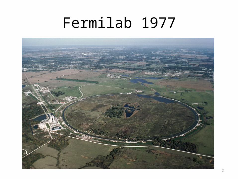
Fermilab 1977
3
Prologue to Tevatron I
• June 1976 to February 1978.– 76 and 77 Woods Hole panels recommend PEP and
ISABELLE for new construction. (The P5 of the day)– Magnet R&D for Energy Saver/Doubler was a distant 3rd
even though the Doubler team had learned how to build superconducting magnets for the Saver /Doubler.
– Bob Wilson resigns, URA accepts his resignation in February and starts the search for a successor
– Leon Lederman accepts URA’s offer to Fermilab’s 2nd Director
4
Prologue to Tevatron I
• In early 1978 CERN approves the pbar-p colliding beams program in the SPS based on an all stochastic cooling pbar source. The ICE experiment provides the evidence that it can be done. The W and Z will be discovered at CERN in 1983.
• After September 1978: Leon– Makes peace in Washington and DOE– Organizes the Armistice Day Shootout of November
11, 1978 for Colliding Beams
5
The Outcome of the Armistice Day Shootout
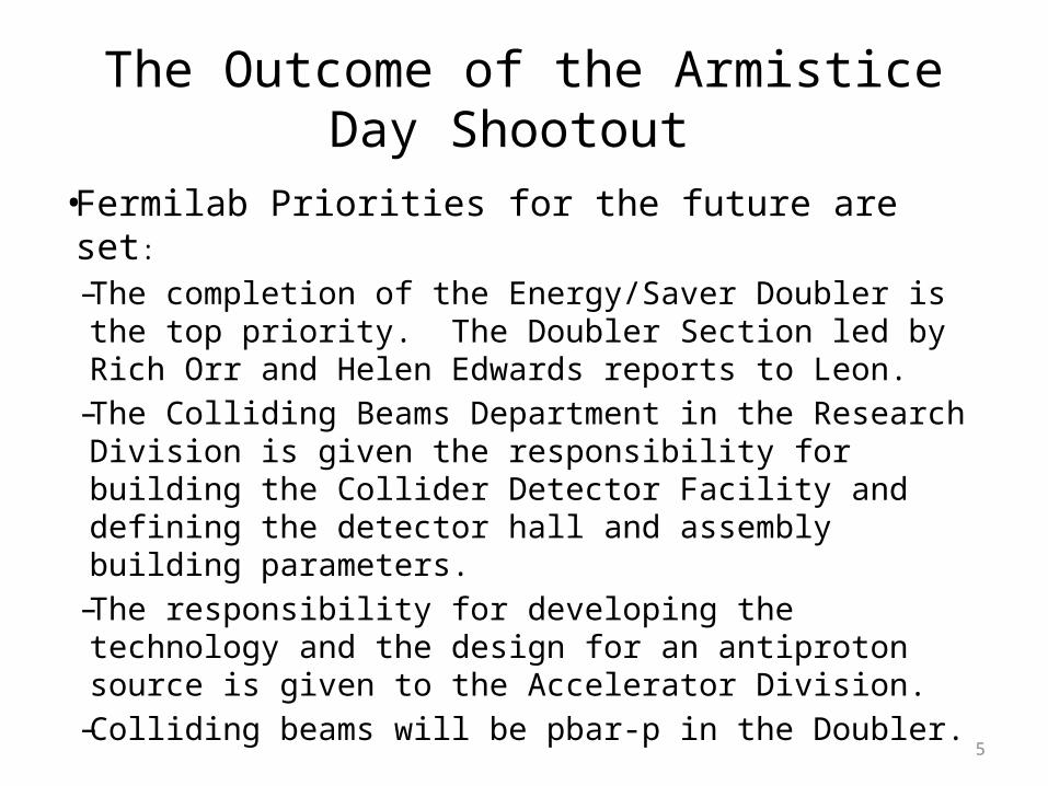
• Fermilab Priorities for the future are set:
– The completion of the Energy/Saver Doubler is the top priority. The Doubler Section led by Rich Orr and Helen Edwards reports to Leon.
– The Colliding Beams Department in the Research Division is given the responsibility for building the Collider Detector Facility and defining the detector hall and assembly building parameters.
– The responsibility for developing the technology and the design for an antiproton source is given to the Accelerator Division.
– Colliding beams will be pbar-p in the Doubler.
6
The Tevatron I Project
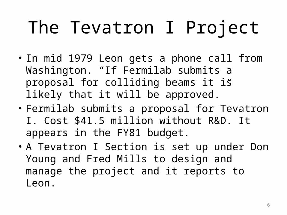
• In mid 1979 Leon gets a phone call from Washington. “If Fermilab submits a proposal for colliding beams it is likely that it will be approved.”
• Fermilab submits a proposal for Tevatron I. Cost $41.5 million without R&D. It appears in the FY81 budget.
• A Tevatron I Section is set up under Don Young and Fred Mills to design and manage the project and it reports to Leon.
7
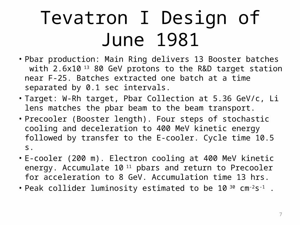
Tevatron I Design of June 1981• Pbar production: Main Ring delivers 13 Booster batches with
2.6x10 13 80 GeV protons to the R&D target station near F-25. Batches extracted one batch at a time separated by 0.1 sec intervals.
• Target: W-Rh target, Pbar Collection at 5.36 GeV/c, Li lens matches the pbar beam to the beam transport.
• Precooler (Booster length). Four steps of stochastic cooling and deceleration to 400 MeV kinetic energy followed by transfer to the E-cooler. Cycle time 10.5 s.
• E-cooler (200 m). Electron cooling at 400 MeV kinetic energy. Accumulate 10 11 pbars and return to Precooler for acceleration to 8 GeV. Accumulation time 13 hrs.
• Peak collider luminosity estimated to be 10 30 cm-2s-1 .
8
Director’s Review of TeV I Design in June 1981
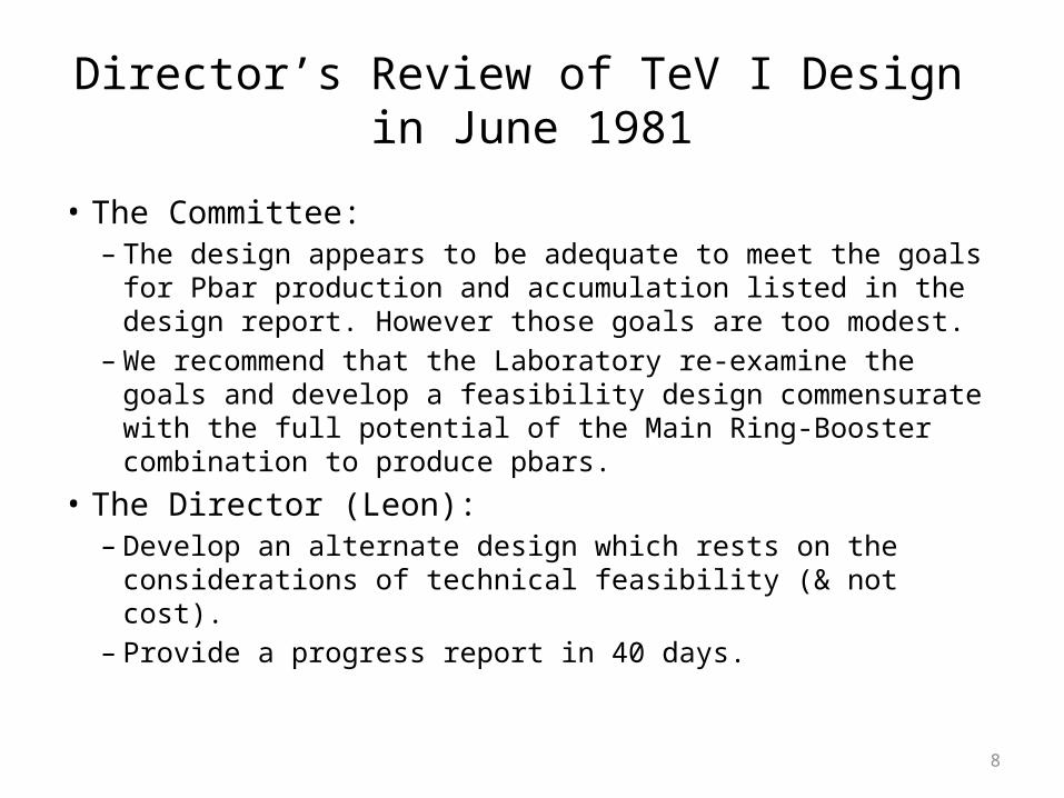
• The Committee:– The design appears to be adequate to meet the goals for Pbar
production and accumulation listed in the design report. However those goals are too modest.
– We recommend that the Laboratory re-examine the goals and develop a feasibility design commensurate with the full potential of the Main Ring-Booster combination to produce pbars.
• The Director (Leon): – Develop an alternate design which rests on the considerations
of technical feasibility (& not cost).– Provide a progress report in 40 days.
9
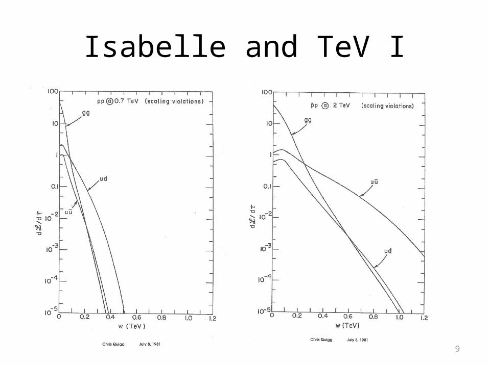
Isabelle and TeV I
10
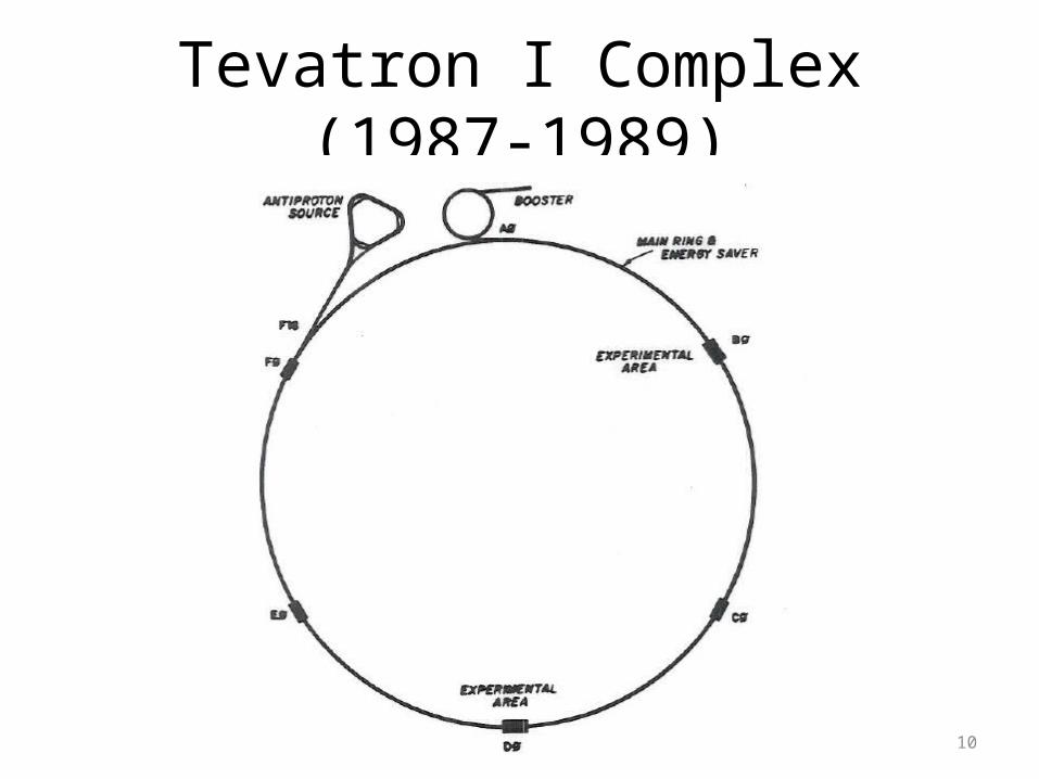
Tevatron I Complex (1987-1989)
11
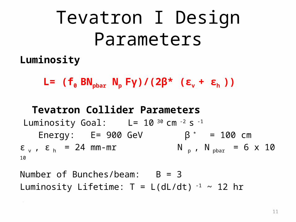
Tevatron I Design Parameters
Luminosity
L= (f0 BNpbar Np Fγ)/(2β* (εv + εh ))
Tevatron Collider Parameters Luminosity Goal: L= 10 30 cm -2 s -1
Energy: E= 900 GeV β * = 100 cm
ε v , ε h = 24 mm-mr N p , N pbar = 6 x 10 10
Number of Bunches/beam: B = 3
Luminosity Lifetime: T = L(dL/dt) -1 ~ 12 hr
TL
12
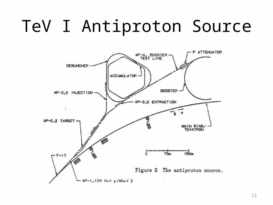
TeV I Antiproton Source
13
Pbar Production
• I Booster batch of 2x10 12 8 GeV protons, 84 bunches, is accelerated to 120 GeV in the Main Ring. Before extraction the bunch time spread is minimized by adiabatic debunching followed by a 90 deg bunch rotation. Beam is delivered to the Pbar target station.
• Protons strike a slowly rotating 5 cm W-Rh target. The proton beam is focused to ~0.2 mm at the target. Number of protons is limited by the energy/cm-3 that can be deposited in the target in 1.6 µ s.
14
Pbar Collection
• Pbars are collected at 8.89 GeV/c. The transverse spot size and time spread of the pbar bunches that emerge from the target are the same as the proton bunches that hit the target.
• A 2cm dia, 15 cm long cylinder of Li just down stream of the target, matches the large angular divergence-small spot size beam into a standard beam transport. Current pulse is ~ 500 KA.
• ~ 5 x 10 7 pbars are transported to and injected into the Debuncher. Transverse emittances are 20 π mm-mr and the momentum spread is 3%.
15
Debuncher• The ~84 bunches of Pbars are injected into stationary 53 MHz
buckets and then undergo a bunch rotation followed by adiabatic debunching. The final momentum spread is reduced from 3% to 0.2%.
• The beam is stochastically cooled for one MR cycle time in both transverse planes (in Run II it is also cooled in momentum). The final transverse emittances are < 5 π mm-mr.
• The beam is transferred to the Accumulator and the next batch of pbars is delivered to the Debuncher for cooling and debunching. Cycle time is 2-3 s.
• A barrier bucket (h=2) creates a gap of ~ 200 ns in the pbar beam in the Debuncher so that it matches the Accumulator circumference.
16
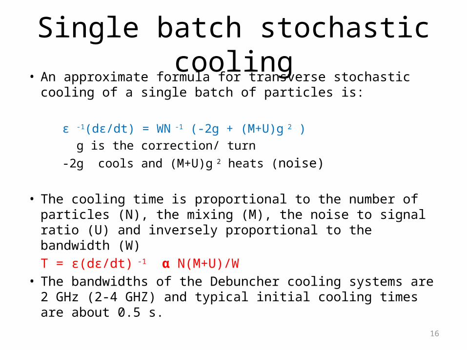
Single batch stochastic cooling• An approximate formula for transverse stochastic cooling of a
single batch of particles is:
ε -1(dε/dt) = WN -1 (-2g + (M+U)g 2 ) g is the correction/ turn -2g cools and (M+U)g 2 heats (noise)
• The cooling time is proportional to the number of particles (N), the mixing (M), the noise to signal ratio (U) and inversely proportional to the bandwidth (W)
T = ε(dε/dt) -1 α N(M+U)/W• The bandwidths of the Debuncher cooling systems are 2 GHz
(2-4 GHZ) and typical initial cooling times are about 0.5 s.
17
Accumulator
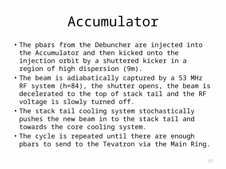
• The pbars from the Debuncher are injected into the Accumulator and then kicked onto the injection orbit by a shuttered kicker in a region of high dispersion (9m).
• The beam is adiabatically captured by a 53 MHz RF system (h=84), the shutter opens, the beam is decelerated to the top of stack tail and the RF voltage is slowly turned off.
• The stack tail cooling system stochastically pushes the new beam in to the stack tail and towards the core cooling system.
• The cycle is repeated until there are enough pbars to send to the Tevatron via the Main Ring.
18
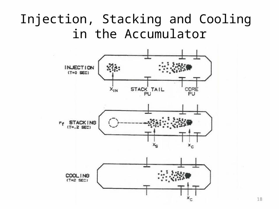
Injection, Stacking and Cooling in the Accumulator
19
Stack Tail Cooling System
• The stack tail pickups are placed in a region of high dispersion (9 m). A displacement of 10 mm radially inward corresponds to an energy decrease of 10 MeV. The kickers that push the beam towards to core are in a region of 0 dispersion.
• The gain of the stack tail pickups decreases with the radial distance from the pickups, which is proportional to energy. The overall system gain is designed to decrease exponentially with energy. Bandwidth 1 GHz (1-2 GHz)
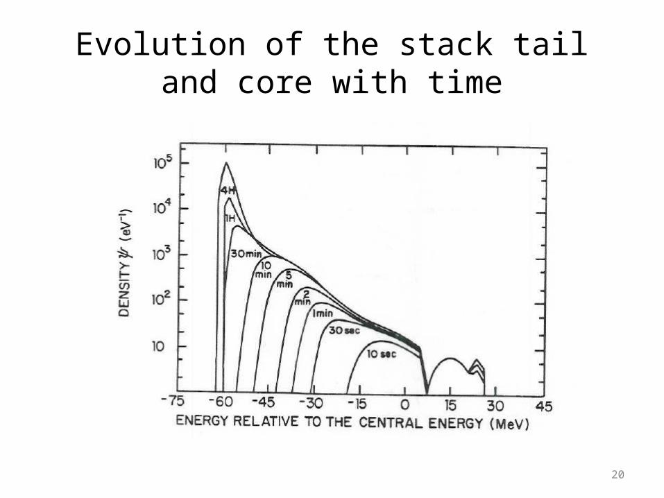
• The beam is cooled slowly where dN/dE is large and quickly where dN/dE is small. An exponential increase in dN/dE will provide a constant flux of pbars into the core momentum cooling system.
20
Evolution of the stack tail and core with time
21
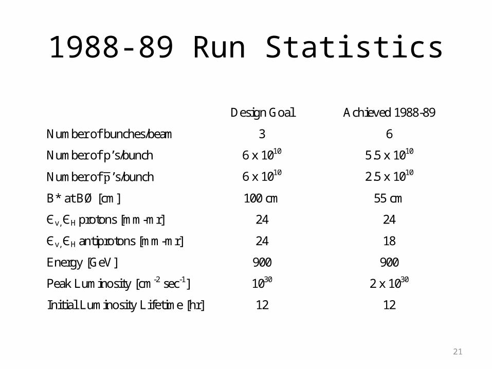
1988-89 Run Statistics
Design Goal Achieved 1988-89
Number of bunches/beam 3 6
Number of p’s/bunch 6 x 10¹⁰ 5.5 x 10¹⁰
Number of ’s/bunch 6 x 10¹⁰ 2.5 x 10¹⁰
Β* at BØ [cm] 100 cm 55 cm
Єv, ЄH protons [mm-mr] 24 24
Єv, ЄH antiprotons [mm-mr] 24 18
Energy [GeV] 900 900
Peak Luminosity [cm-2 sec-1] 1030 2 x 1030
Initial Luminosity Lifetime [hr] 12 12
22
Phase I Upgrade of the Fermilab Accelerator Complex
The elements of the phase I upgrade for run I were:• Matched low beta insertions for CDF (B0) and D0• Electrostatic separators create helical orbits and reduce
the number of beam-crossings from 12 to 2 (CDF and D0)• Linac energy upgrade from 200 MeV to 400 MeV• Reliability improvements to the pbar target station• Incremental improvements to stochastic cooling systems. • Improvements to the controls and beam position
monitors systems
23
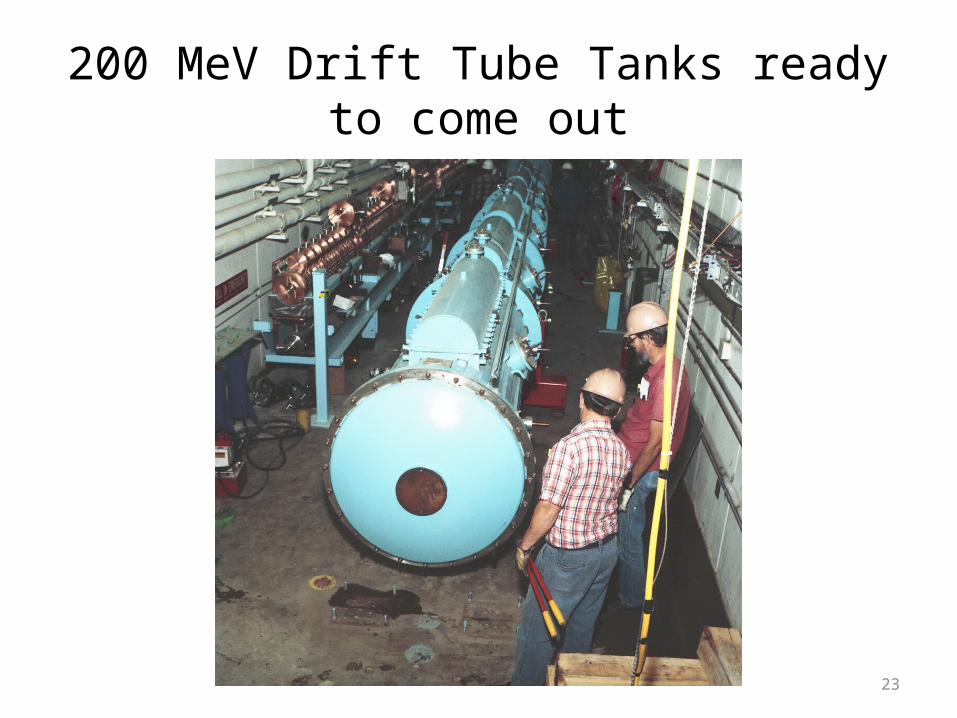
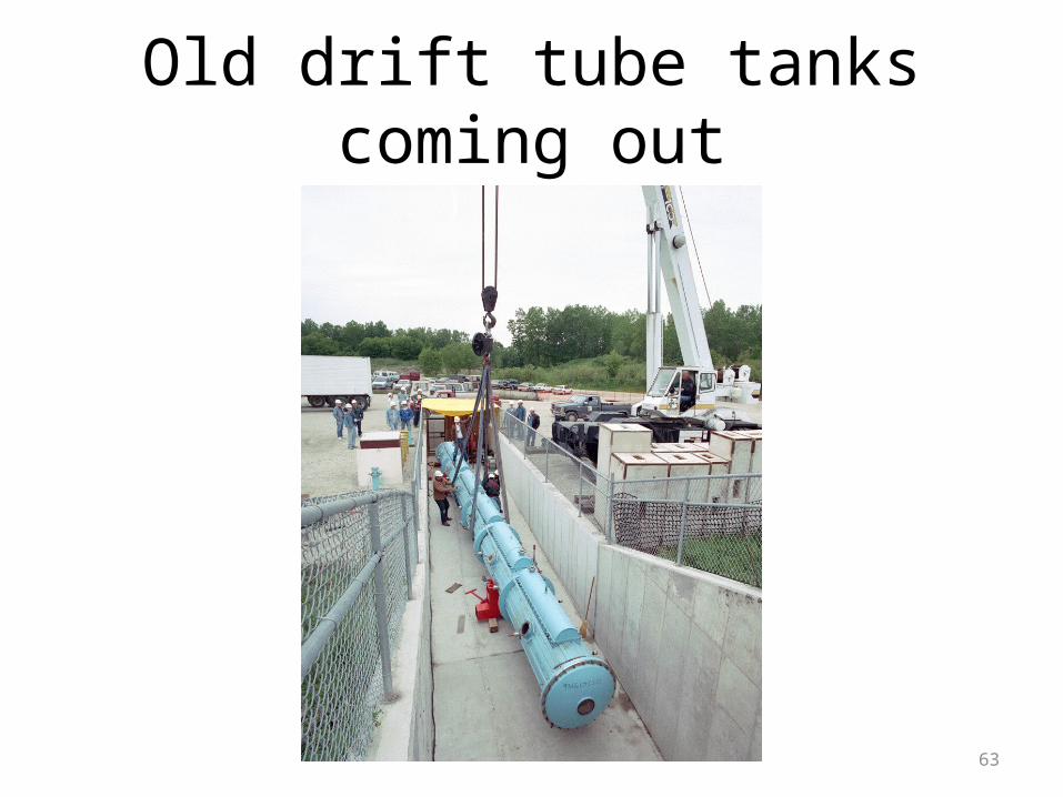
200 MeV Drift Tube Tanks ready to come out
24
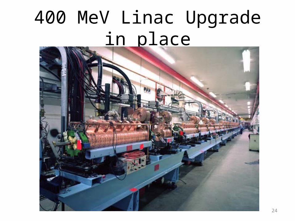
400 MeV Linac Upgrade in place
25
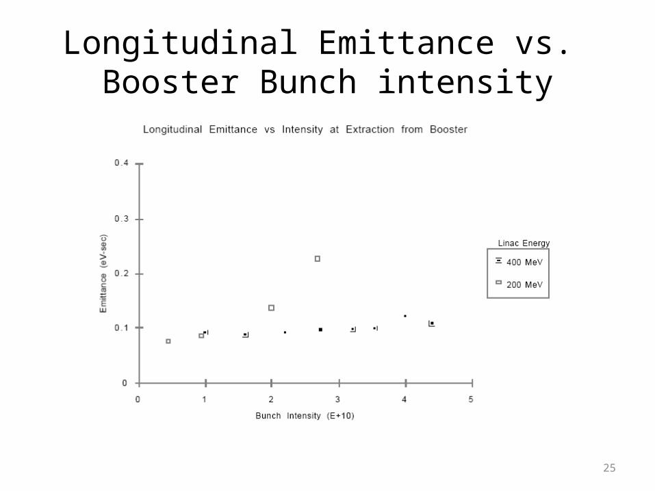
Longitudinal Emittance vs. Booster Bunch intensity
26
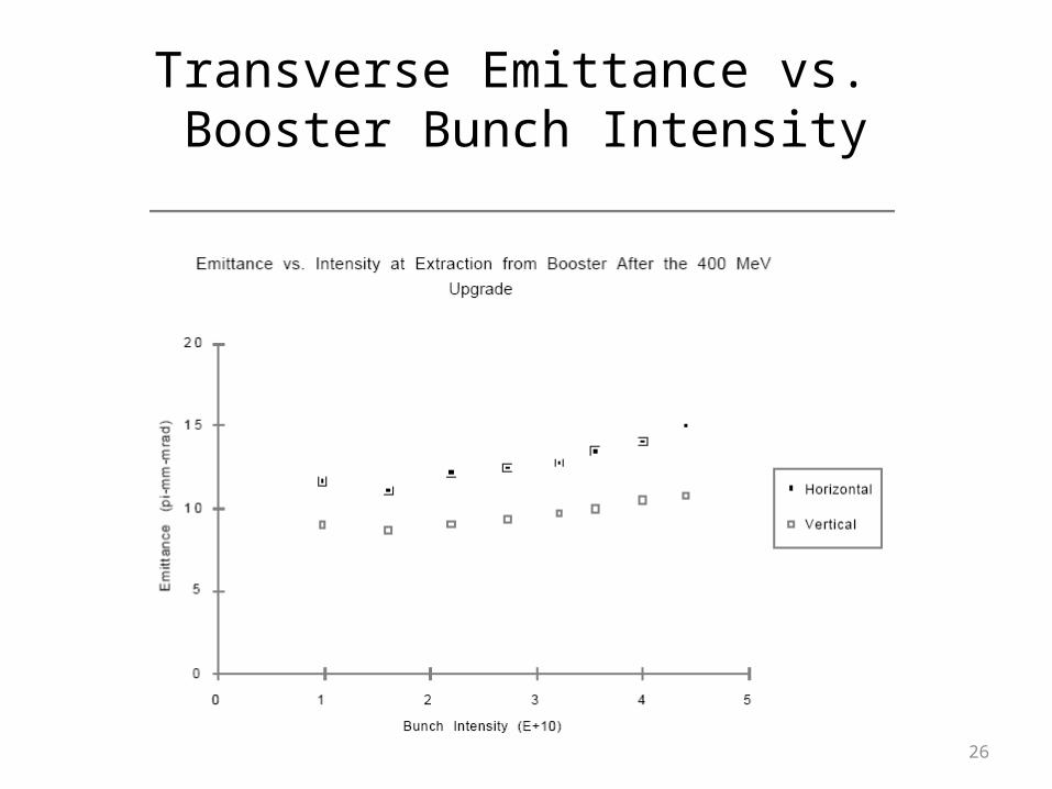
Transverse Emittance vs. Booster Bunch Intensity
27
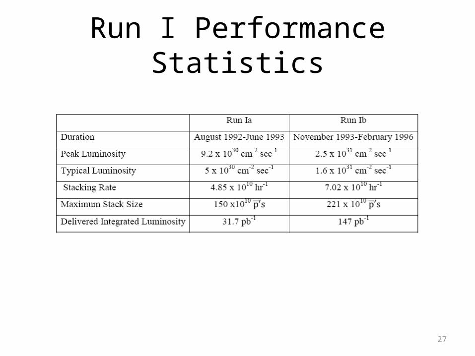
Run I Performance Statistics
28
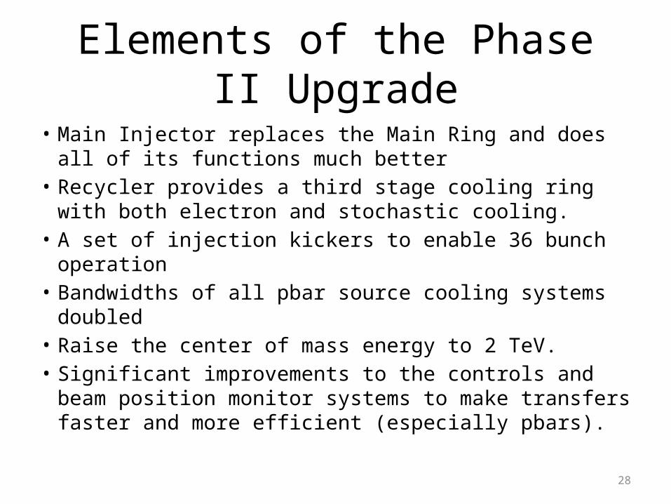
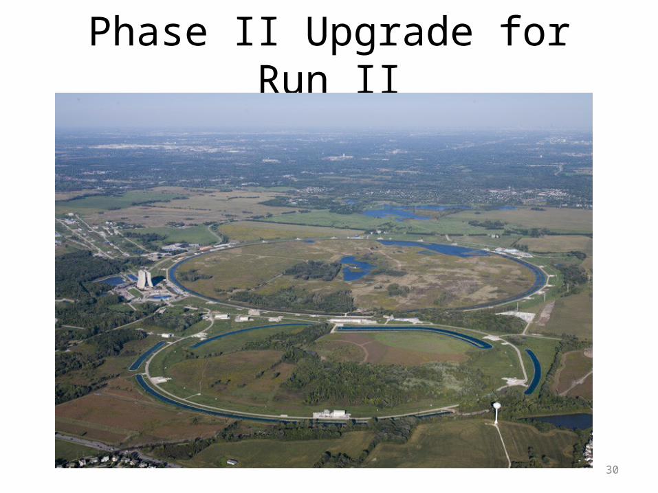
Elements of the Phase II Upgrade
• Main Injector replaces the Main Ring and does all of its functions much better
• Recycler provides a third stage cooling ring with both electron and stochastic cooling.
• A set of injection kickers to enable 36 bunch operation• Bandwidths of all pbar source cooling systems doubled• Raise the center of mass energy to 2 TeV. • Significant improvements to the controls and beam
position monitor systems to make transfers faster and more efficient (especially pbars).
29
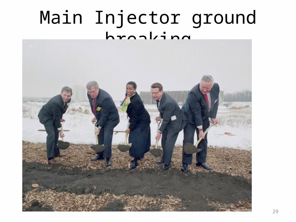
Main Injector ground breaking
30
Phase II Upgrade for Run II
9/15/97
32
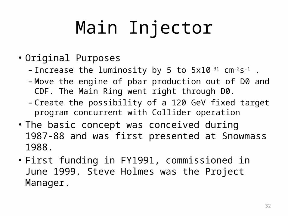
Main Injector
• Original Purposes– Increase the luminosity by 5 to 5x10 31 cm-2s-1 .– Move the engine of pbar production out of D0 and
CDF. The Main Ring went right through D0.– Create the possibility of a 120 GeV fixed target
program concurrent with Collider operation • The basic concept was conceived during 1987-88
and was first presented at Snowmass 1988.• First funding in FY1991, commissioned in June
1999. Steve Holmes was the Project Manager.
33
Main Injector
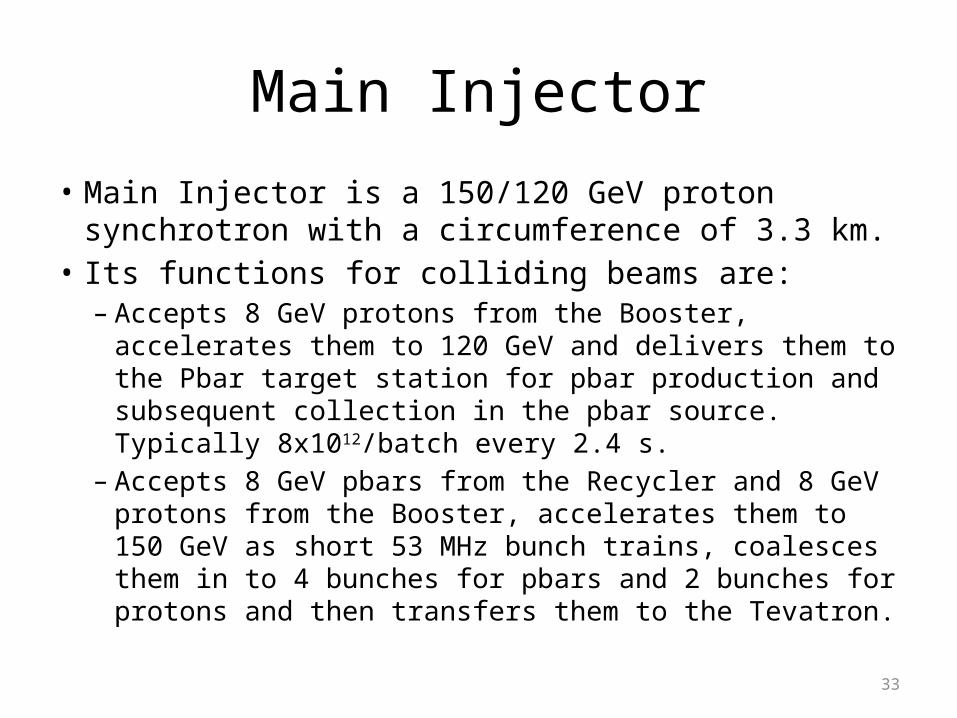
• Main Injector is a 150/120 GeV proton synchrotron with a circumference of 3.3 km.
• Its functions for colliding beams are:– Accepts 8 GeV protons from the Booster, accelerates them to
120 GeV and delivers them to the Pbar target station for pbar production and subsequent collection in the pbar source. Typically 8x10¹²/batch every 2.4 s.
– Accepts 8 GeV pbars from the Recycler and 8 GeV protons from the Booster, accelerates them to 150 GeV as short 53 MHz bunch trains, coalesces them in to 4 bunches for pbars and 2 bunches for protons and then transfers them to the Tevatron.
34
Turning the Main Injector on
35
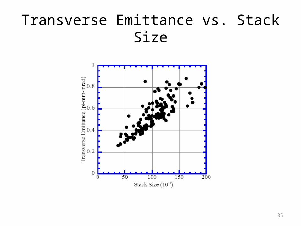
Transverse Emittance vs. Stack Size
36
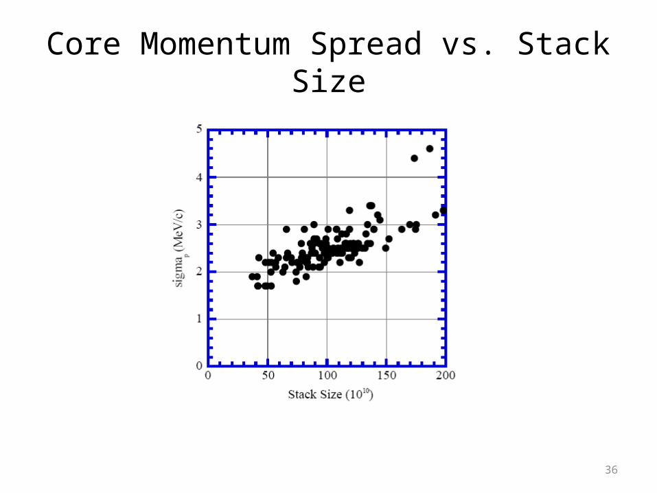
Core Momentum Spread vs. Stack Size
37
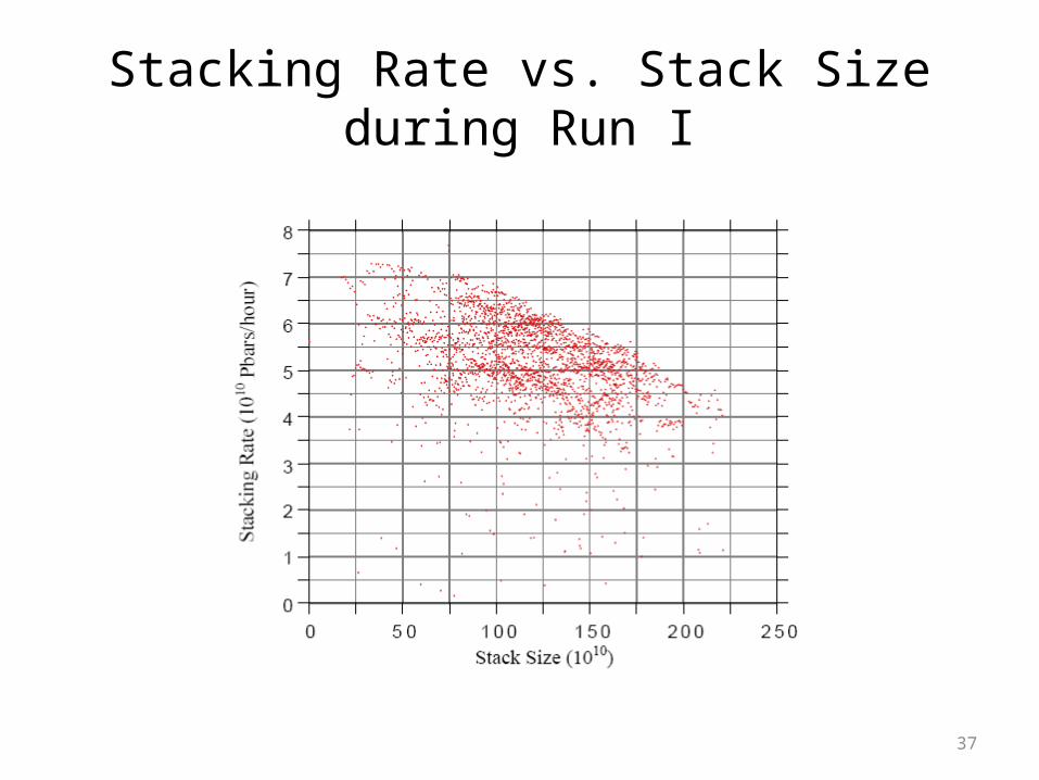
Stacking Rate vs. Stack Sizeduring Run I
38
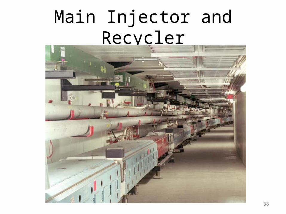
Main Injector and Recycler
39
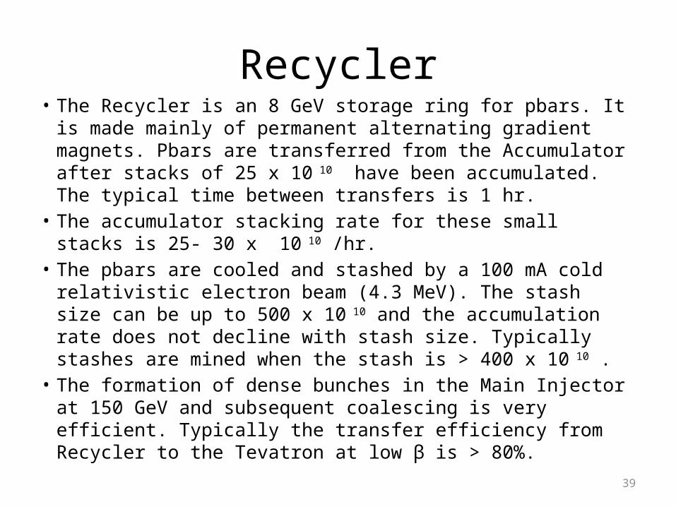
Recycler• The Recycler is an 8 GeV storage ring for pbars. It is made mainly
of permanent alternating gradient magnets. Pbars are transferred from the Accumulator after stacks of 25 x 10 10 have been accumulated. The typical time between transfers is 1 hr.
• The accumulator stacking rate for these small stacks is 25- 30 x 10 10 /hr.
• The pbars are cooled and stashed by a 100 mA cold relativistic electron beam (4.3 MeV). The stash size can be up to 500 x 10 10 and the accumulation rate does not decline with stash size. Typically stashes are mined when the stash is > 400 x 10 10 .
• The formation of dense bunches in the Main Injector at 150 GeV and subsequent coalescing is very efficient. Typically the transfer efficiency from Recycler to the Tevatron at low β is > 80%.

40
Pbar Source and the Main Injector from Wilson Hall
Booster to MI 8 GeV Line
41
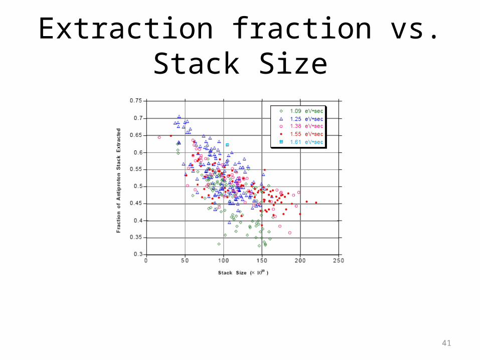
Extraction fraction vs. Stack Size
42
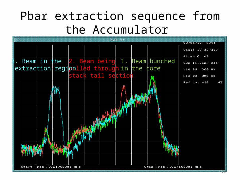
Pbar extraction sequence from the Accumulator
1. Beam bunched in the core
2. Beam being pulled throughstack tail section
3. Beam in the extraction region
43
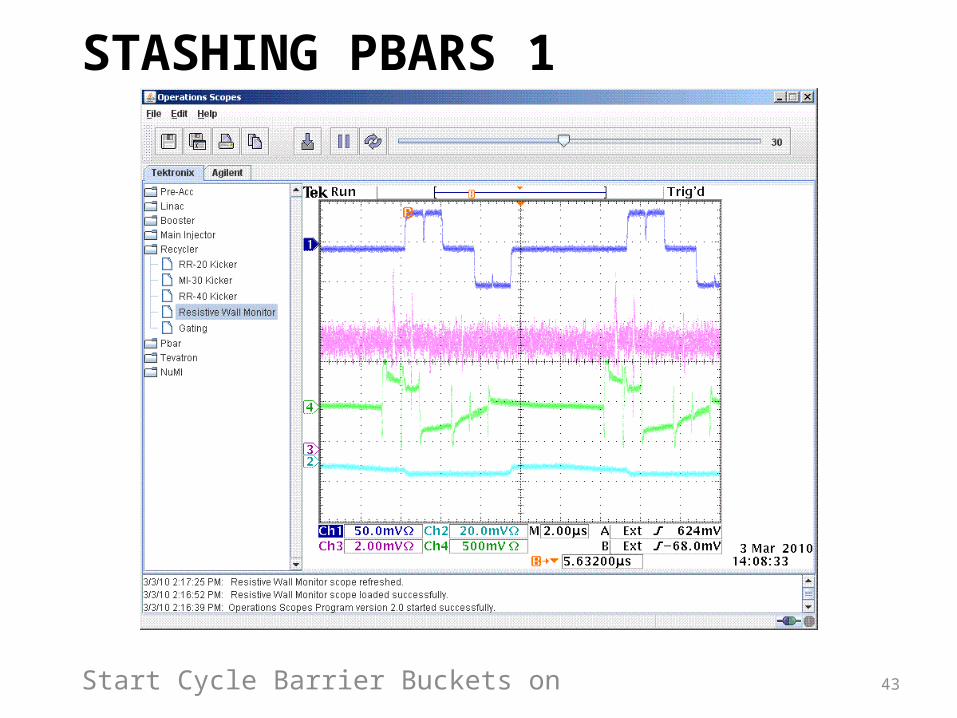
STASHING PBARS1
Start Cycle Barrier Buckets on
44
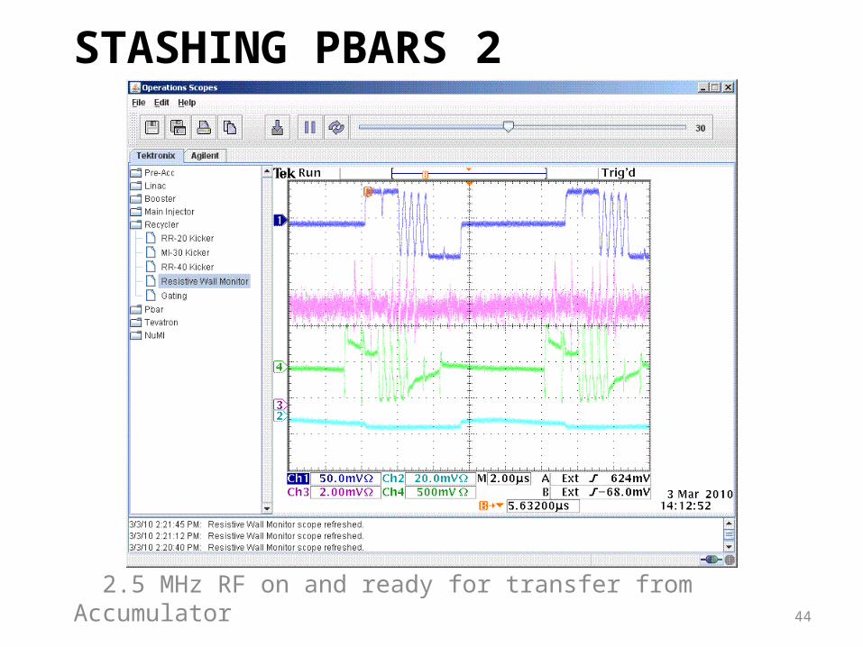
STASHING PBARS2
2.5 MHz RF on and ready for transfer from Accumulator
45
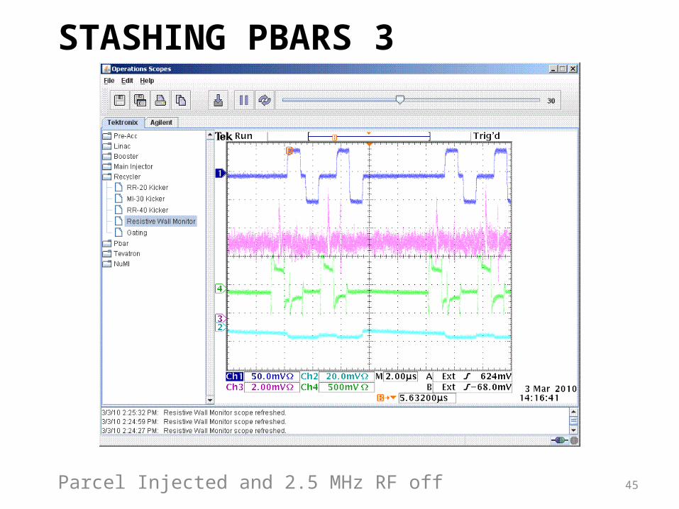
STASHING PBARS3
Parcel Injected and 2.5 MHz RF off
46
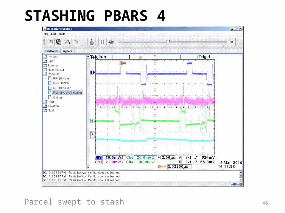
STASHING PBARS4
Parcel swept to stash
47
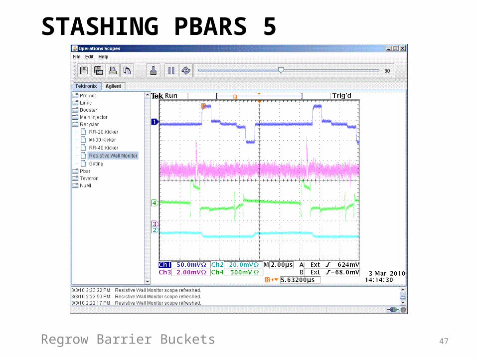
STASHING PBARS5
Regrow Barrier Buckets
48
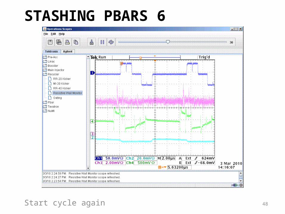
STASHING PBARS6
Start cycle again
49
Selection of the number of Bunches, B• L is proportional to B if Np and Npbar are fixed • The bunch spacing is determined by the
selected sub-harmonic of the Tevatron 53 MHz RF system (h=3x7x53 = 1113). – h=53 provides a bunch spacing of 396 ns. It is
being used in Run II to produce 3 groups of 12 bunches with 400 ns spacing for each beam.
– The separation of the groups, about 2 µ s, is used for aborts, injection and cogging.
– 36 bunches/beam is standard in Run II.
50
Collider Operation with the Main Injector and Recycler
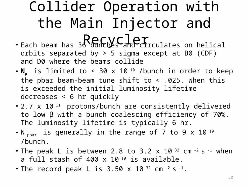
• Each beam has 36 bunches and circulates on helical orbits separated by > 5 sigma except at B0 (CDF) and D0 where the beams collide
• Np is limited to < 30 x 10 10 /bunch in order to keep the pbar beam-beam tune shift to < .025. When this is exceeded the initial luminosity lifetime decreases < 6 hr quickly
• 2.7 x 10 11 protons/bunch are consistently delivered to low β with a bunch coalescing efficiency of 70%. The luminosity lifetime is typically 6 hr.
• N pbar is generally in the range of 7 to 9 x 10 10 /bunch.• The peak L is between 2.8 to 3.2 x 10 32 cm -2 s -1 when a full
stash of 400 x 10 10 is available. • The record peak L is 3.50 x 10 32 cm -2 s -1.
51
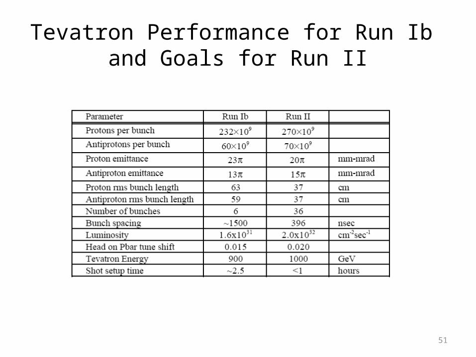
Tevatron Performance for Run Ib and Goals for Run II
52
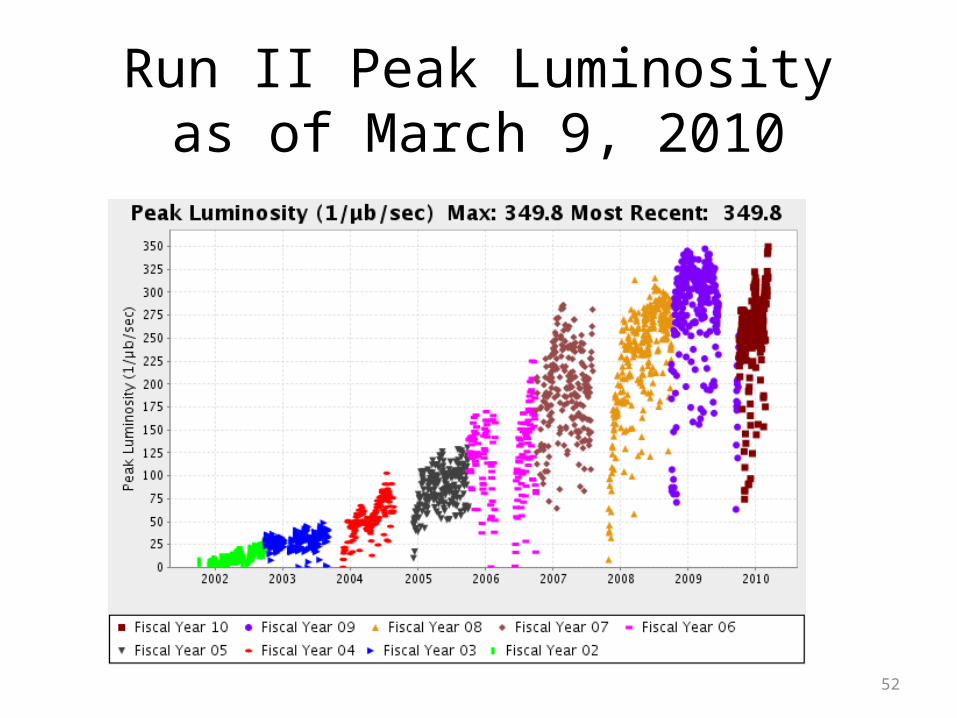
Run II Peak Luminosityas of March 9, 2010
53
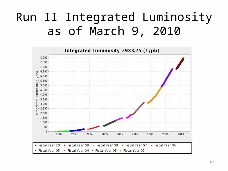
Run II Integrated Luminosityas of March 9, 2010

54
Epilogue
• The Tevatron Collider has worked extremely well for 25 years and is still working well.
• It has enabled CDF and D0 to discover the top quark and observe important features of the standard model for the first time.
• By the end of FY2011 it will have delivered about 12 fb-1 to both CDF and D0. I hope that there is at least one more important discovery in that data.
• Its success is a great tribute to the Fermilab staff, all five Directors and DOE.
55
Additional Slides
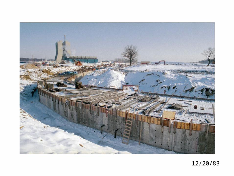
12/20/83
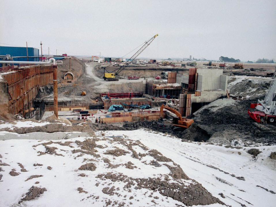
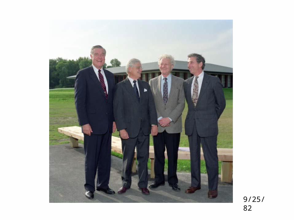
9/25/82
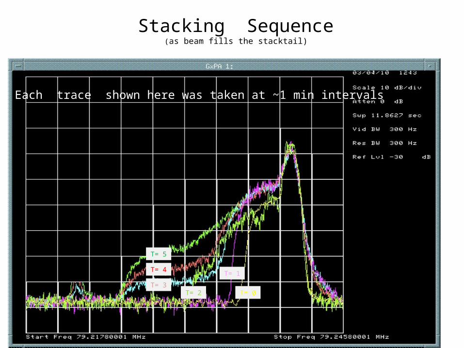
Stacking Sequence(as beam fills the stacktail)
Each trace shown here was taken at ~1 min intervals
T= 0
T= 1
T= 2T= 3
T= 4
T= 5
63
Old drift tube tanks coming out
64
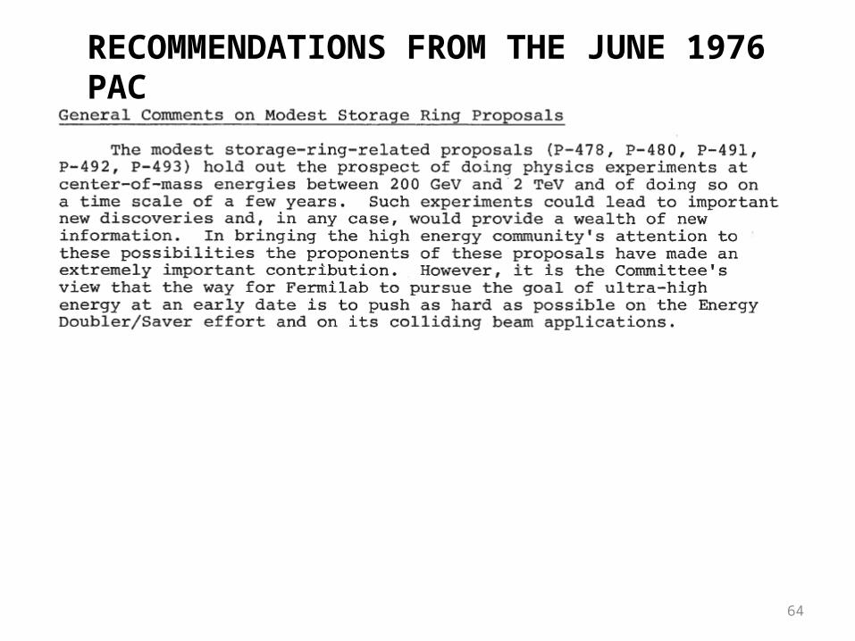
RECOMMENDATIONS FROM THE JUNE 1976 PAC