the state-of-the-art technology of nox control
TRANSCRIPT

ELSEVIER Catalysis Today 29 (1996) 109-115
CATALYSIS TODAY
The state-of-the-art technology of NO x control
Fumito Nakajima *, Ikuhisa Hamada Kure Research Laboratory, Babcock-Hitachi K.K., Takara-machi, Kure-shi, Hiroshima-ken 737, Japan
Abstract
The TiO2-based DeNOx catalyst which is now commercially implemented world-wide is described, emphasizing the importance of the resistance to SOx-poisoning and plugging by particulates. Various NOx reduction technologies are compared and recent trends in catalytic DeNOx installations in Japan are reviewed. For wider applications and to meet the stringent emission requirements, newly developed DeNOx catalysts such as for high-temperature gas turbine exhaust and for simultaneous removal of NO x and CO are also introduced.
Keywords: NO x control; DeNO~
1. Introduction
Innovation in industrial catalysis has always been derived from the strong social and indus- trial needs. Because of the urgent requirements for ammonia in the manufacturing of explosives in Germany during World War I, the first break- through in ammonia synthesis with the iron oxide catalyst was resulted from the work of Haber and Bosch. Similarly, the TiO2-based catalyst for NO x removal was invented by the author and his colleagues in 1973, in response to the urgent needs to mitigate air pollution, especially photochemical smog in urban and industrial area of Japan.
Both combustion control and post-combus- tion flue gas treatment are currently available for the reduction of NO x emission from station- ary combustion sources. With the combustion control and the low NO x burner, the NO x emis-
sion can be reduced to 100 or 200 ppm. In order to meet the strict emission standard, the flue gas treatment is required. Among many proposed methods, the catalytic NO x removal process has been found most feasible and the selective cat- alytic reduction (SCR) with ammonia is widely implemented to the utility boilers and other industrial combustion facilities.
Commercial application of the catalytic DeNO x has been initiated in Japan since 1977, four years from our invention of the TiO2-based catalyst. It is recognized that the industrial suc- cess of the catalytic removal of NO x could not be realized without the invention of the TiO 2- based catalyst. The TiO2-based catalyst predom- inates in SCR DeNO x process as the iron oxide catalyst in ammonia synthesis.
2. Invention of the TiO2-based catalyst
* Corresponding author. A key element of the catalytic DeNO x system
is a 'high performance' catalyst. Several hun-
0920-5861/96/$32.00 © 1996 Elsevier Science B.V. All rights reserved SSDI 0920-5861(95)00288-X

110 F. Nakafima, 1. Hamada / Catalysis Today 29 (1996) 109-115
Table 1 Properties of the typical DeNO x catalysts
Catalyst TiO2-type Fe203-type Al203-type
Catalytic activity High Medium Low Resistance to SO x High Low a Low b Selectivity High Low Low
( > 450°C) ( > 450°C) Oxidation of SO 2 Low High High to SO 3 Regeneration c Possible Impossible Impossible
= Formation of Fe2(SO4) 3. Formation of AI2(SO4) 3.
c Removal of deposited NH4HSO 4 by heating above 300°C.
100
0~ 80 e.- O • ~ 6o
c 40 8 o 20 Z
TiO=-based Catalyst
"~-mp. 350"c -*- 5"c s v 50,000/h NO 300 ppm
~ . . NH= 300 - SO= 500 - SOs 500 "
Fe=O3-based Catalyst o2 3 % !HaO 12 "
0 ~ 0 50 100 150 200
Time (h)
Fig. 1. SO x poisoning test.
dreds of catalysts were examined in the early stage of catalyst development. The catalysts studied are classified as shown in Table 1. Metal oxide catalysts, such as Fe203, Fe203- C r 2 0 3 , F e 2 0 3 - W O 3 , F e 2 0 3 supported on A1203 and V205 supported on A1203 were proved to have a high activity for N O - N H 3 reaction in the presence of a large excess of oxygen. These catalysts, however, lose their activity easily in a few hundred hours due to SO x poisoning. The catalyst components such as Fe203 and A1203 easily react with SO x to form their sulfates at operating temperatures, i.e., 200-400°C. A drastic decrease of pore volume and surface area of the catalysts was observed with the formation of sulfates. As a result of extensive exploratory studies of cata- lysts, it was found that TiO 2 does not react with SO x and shows a high activity for N O - N H 3 reaction. The SO x poisoning test indicates a high stability of the TiO2-based catalysts as shown in Fig. 1. The experiments were per- formed with a test gas containing 500 ppm SO 3 using either a WO 3 (15 wt.-%)-Fe203 (85 wt.- %) catalyst or a WO 3 (10 wt.-%)-TiO 2 (90 wt.-%) catalyst. Fig. 1 indicates that the catalyst composed mainly of Fe203 lose its activity very rapidly. On the other hand, the WO3-TiO 2 cata- lyst, composed mainly of TiO 2, maintained the initial activity for 200 h. The most outstanding issue of this invention is that the TiO2-based catalysts exhibit resistance to SOx poisoning over a wide range of temperatures, 200-600°C.
TiO 2 essentially reacts with neither SO 3 nor SO 2 at temperatures above 200°C and, there- fore, is able to keep its structure over a long period of exposure to SOx-containing flue gases.
Patents disclose the TiO2-based catalysts for selective catalytic reduction of NO x with NH 3 [1,2]. Second components of the TiO2-based catalysts are selected from a group of V205, MoO 2, WO 3, Fe203, CoO, NiO, MnO 2, Cr203, CuO, U308 and so on. The TiO2-based catalysts show high activity and selectivity for the reac- tion between NO and NH 3 in the presence of large excess of oxygen, at a temperature range of 200 to 500°C, as shown in Fig. 2. TiO 2 plays a role, not only as a catalyst support, but also as a promoter of the catalytic reaction.
It is known that NO x is selectively reduced by NH 3 in the presence of a large excess of 02.
100
• .--. 8O
4oi t -
8 O Z 2O
TiO--,-MoO= NO 300 ppm NH= 360 # SO= 500 # O2 3 % CO= 12 - H ~ 12 -
200 250 300 350 400 450
Temperature (*C)
Fig. 2. Catalytic activity of various catalysts on NO-NH 3 reac- tion.

F. Nakajima, L Hamada / Catalysis Today 29 (1996) 109-115 111
100 "O"IZD
A 400°C / 80 0 350"c _ ~ u
._o ~'" 60 [] 300°(3_ S ~NO+NH3(I:I)
c 40 30,000/h 8 ~ INO 300 ppm O /~J I NH3 0~370ppm Z 20 ~ 102 3 %
/ [Nz balance
0 0 . . . . . . . . . . 0.2 0.4 0.6 0.8 1 1.2 1.4
[NH3]/[NO] (mole ratio)
Fig. 3. NO conversion as a function of [NH3]/[NO] ratio -- Effect of temperature.
The reaction stoichiometry is elucidated as fol- lows [3]:
' (1 ) NO + NH 3 + 7Oz = N 2 +
A careful experiment was carried out in order to determine the reaction stoichiometry of NO x and NH 3. Fig. 3 shows the NO conversion as a function of N H 3 / N O ratio at varied tempera- tures. The reaction proceeds in one to one molar ratio of NH 3 to NO. Co-existence of excess oxygen is necessary to enhance the N O - N H 3 reaction.
In the NO2-NH 3 system, the overall reaction is given as
7 3NO 2 + 4NH 3 = ~-N 2 + 6H20 (2)
No effect of co-existence of oxygen is observed for the N O z - N H 3 reaction.
In the N O - N O z - N H 3 system, the overall reaction is given as,
NO + N O 2 + 2NH 3 = 2N 2 + 3H20 (3)
The reaction of equimolar N O - N O 2 with NH 3 is the fastest among three reactions. When both NO and NO 2 are contained in the flue gas, the reaction between equimolar N O - N O 2 and NH 3 proceeds first and the reaction of remaining NO or NO 2 follows.
The most part of NO x in the actual combus- tion flue gases is contained as NO and NO 2 is less than one tenth of NO. In the industrial
DeNO x practice, therefore, NH 3 addition to the flue gas has to be controlled based on the one-to-one ratio of the DeNO~ reaction.
3. Commercial implementation
A typical flue gas treatment for a boiler is shown in Fig. 4. The flue gas from a boiler economizer at a temperature of 300 to 400°C is mixed with NH 3 and introduced into the NO x removal catalyst reactor, where NO/ is reduced to N 2 and H 2 0 by reacting with N H 3 and 0 2.
The flue gas is then heat-exchanged in an air heater. An electrostatic precipitator for dust re- moval and a desulfurization unit, if necessary, are installed downstream of the DeNO x reactor. Fig. 5 shows an example of the catalytic DeNO x reactor.
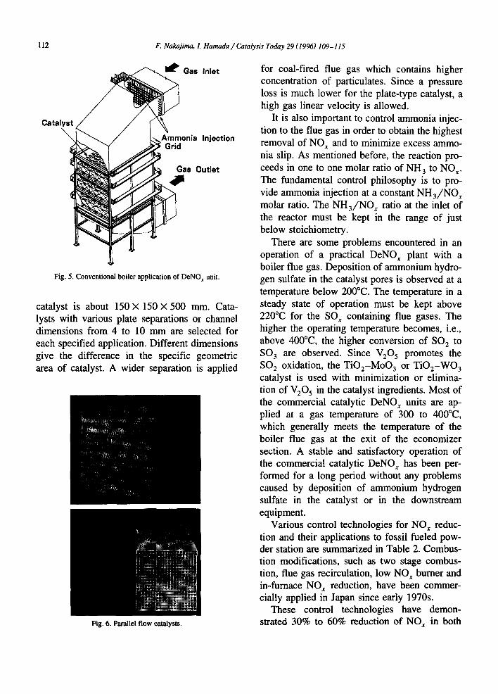
A few important points encountered at the stage of the commercial implementation of the catalytic DeNO x should be mentioned. Since the volume of flue gas to be treated is extraordinar- ily large, for example, 2 000 000 Nm 3 h - ~ for 700 MW fossil fueled power plant and contains various amounts of particulates, it is important to minimize pressure loss across the catalyst bed and to prevent plugging with the particulates. A fixed bed reactor with tablet- or granular-type catalyst is apt to be plugged with particulate matters. Parallel-flow reactor is the most effec- tive and reliable choice to prevent plugging. Two types of the parallel-flow catalyst, plate- type and honeycomb monolith-type, are widely employed. Pictures of the catalyst units are shown in Fig. 6. Catalyst plate elements having notches are arranged and packed in the catalyst unit, the size of which is 500 × 500 × 500 mm. The extruded element of the honeycomb-type
NH3
GGH Stack DeSOx
Fig. 4. Typical flue gas treatment system with DeNO x unit.
112 F. Nakajima, L Hamada / Catalysis Today 29 (1996) 109-115
Catalyst
~ Ga$ Inlet
J Ammonia Injection Grid
s Outlet
Fig. 5. Conventional boiler application of DeNO x unit.
catalyst is about 150 x 150 X 500 mm. Cata- lysts with various plate separations or channel dimensions from 4 to 10 mm are selected for each specified application. Different dimensions give the difference in the specific geometric area of catalyst. A wider separation is applied
Fig. 6. Parallel flow catalysts.
for coal-fired flue gas which contains higher concentration of particulates. Since a pressure loss is much lower for the plate-type catalyst, a high gas linear velocity is allowed.
It is also important to control ammonia injec- tion to the flue gas in order to obtain the highest removal of NO x and to minimize excess ammo- nia slip. As mentioned before, the reaction pro- ceeds in one to one molar ratio of NH 3 to NO x. The fundamental control philosophy is to pro- vide ammonia injection at a constant NH 3/NO x molar ratio. The NH3/NO x ratio at the inlet of the reactor must be kept in the range of just below stoichiometry.
There are some problems encountered in an operation of a practical DeNO x plant with a boiler flue gas. Deposition of ammonium hydro- gen sulfate in the catalyst pores is observed at a temperature below 200°C. The temperature in a steady state of operation must be kept above 220°C for the SOx containing flue gases. The higher the operating temperature becomes, i.e., above 400°C, the higher conversion of SO 2 to SO 3 are observed. Since V205 promotes the SO 2 oxidation, the TiO2-MoO 3 or TiO2-WO 3 catalyst is used with minimization or elimina- tion of V205 in the catalyst ingredients. Most of the commercial catalytic DeNO~ units are ap- plied at a gas temperature of 300 to 400°C, which generally meets the temperature of the boiler flue gas at the exit of the economizer section. A stable and satisfactory operation of the commercial catalytic DeNO~ has been per- formed for a long period without any problems caused by deposition of ammonium hydrogen sulfate in the catalyst or in the downstream equipment.
Various control technologies for NO x reduc- tion and their applications to fossil fueled pow- der station are summarized in Table 2. Combus- tion modifications, such as two stage combus- tion, flue gas recirculation, low NO~ burner and in-furnace NO x reduction, have been commer- cially applied in J a p a n since early 1970s.
These control technologies have demon- strated 30% to 60% reduction of NOx in both

F. Nakajima, I. Hamada / Catalysis Today 29 (1996) 109-115 113
Table 2 Application of NO x control to fossil fueled power stations
NO x control technology Fuel NO~ level (ppm) Start of commercial application
(1) Two stage combustion, Gas ca. 55-110 1972 Flue gas recirculation
Oil ca. 95-180 1972 Coal ca. 300-350 1972
(2) (1) + Low NO x burner Gas ca. 40-100 1975 Oil ca. 85-180 1974 Coal ca. 160-300 1975
(3) In-furnace NO~ reduction Gas ca. 40-60 1985 Oil ca. 50-85 1981
(4) Catalytic DeNO x Gas ca. 10-20 1977 Oil ca. 20-30 1977 Coal ca. 50-80 1980
new and existing boiler plants. However, we need to add the catalytic DeNO x units to the combustion modifications, because the emission regulation for NO~ is very strict to the utility boilers and combined cycle plants. Commercial implementations of the catalytic DeNO~ started in 1977 and have expanded rapidly especially in Japan.
According to the survey of the Environmen- tal Agency of Japan, the cumulative number of the installations of NO x control in Japan amounts to 826 units in 1993 as shown in Fig. 7. The number of installations for various industries is as follows. Utility industry: 173 units (20.9%);
tO0
50
3,00(
2,50(
'~ 2,00(
""S. 1,0(X
0
xlOC~Jm~h 300
250 ............................................................................
..................... t~so~ ................... ~ / . / - .........
y . , , ........ •
....... ; i ...................................................... | f , , e ° ~
I ! I
~i,.,IX I, ooB~eo~o "
$~ma.ome aee~°
70 75 80 B5 90 95 Year
Fig. 7. Commercial installations of DeNO x and DeSO~ in Japan.
waste incineration: 139 units (16.8%); chemical industry: 99 units (12.0%). Total capacity of the installations is estimated to be 243 million m 3 per h of the flue gas treated. Main contributor is the utility industry. Capacity of the flue gas from utility power plants, of which NO x emis- sion is controlled, amounts to 196 million m 3 per h and accounts for 80% of the total capac- ity. Although the number of DeNO x is less than a half of than that of DeSO x, the total gas volume of capacity of DeNO x exceeds that of DeSO x.
All utility companies in Japan have intro- duced the catalytic DeNO x and more than 100 units are fitted to the utility boilers and com- bined cycle plants. Total capacity fitted with the catalytic DeNO x units is more than 50000 MW which corresponds to 50% of the fossil-fueled power generation of Japan. Japanese utility companies are required compulsively to equip their new fossil-fueled power plants with the catalytic DeNOx units.
4. New development of catalytic DeNO~
It is clear that the catalytic DeNO x process using the TiO2-based catalyst is a well estab- lished technology. Further developments should be considered here.

114 F. Nakajima, L Hamada / Catalysis Today 29 (1996) 109-115
100 o~ddant in ject ion
"~ 40 A : for oonventional boiler 0 z B : for g a s turbine
20 . . . . . . . . . . . . . . . . . . . . . . . . . . . . . . .
I f f I I "100 200 300 400 500 600
Temperature 0C)
Fig. 8. High and low temperature applications of catalytic DeNO~.
1. Extended applications to high and low tem- peratures.
2. High efficiency of NO x removal (more than 90%).
3. Simultaneous removal of CO and NO x. 4. SCR with urea or other N compounds. 5. SCR with hydrocarbon. 6. Direct decomposition. 7. Simultaneous removal of NO~ and SO x.
Gas turbines and some industrial furnaces require high temperature applications for the catalytic DeNO x with ammonia. The most ex- tensive applied catalyst is used at temperatures from 300 to 400°C. In Fig. 8, the performance of new catalyst (B) for high temperature appli- cations is shown in comparison to the conven- tional one (A). The new catalyst consists of TiO2-WO 3 and exhibits high activity and ther- mal stability at the temperatures from 450 to 600°C. The high temperature catalyst is applica- ble to the exhaust from industrial gas turbines, the temperature of which is usually 550 to 600°C. Several commercial DeNO~ units for the industrial gas turbine are operating satisfacto- rily.
For the low temperature applications, we pro- posed an oxidant or NO 2 injection to the com- bustion flue gas in addition to the ammonia injection. If we could prepare equimolar N O - NO 2 in the flue gas, the NH3-NO ~ reaction would be strikingly accelerated even at a tem- perature below 200°C. It is expected to obtain a
high efficiency of NO x removal for low temper- ature applications without heating up to above 300°C and consequently to save energy con- sumption in the catalytic DeNO/system.
Stoichiometry of NO x reduction is a one to one molar ratio of NH 3 to NO x. In order to minimize excess NH 3 slip, the operating molar ratio is kept to less than 1.0; for example 0.8 to 0.9. If the excess NH 3 slip is not allowed, it is difficult to attain more than 90% removal. A new catalyst, which has an activity to decom- pose excess NH 3 to nitrogen and water as well as to promote NHa-NO x reaction in the pres- ence of oxygen, was recently developed in our laboratory. Oxidation of NH 3 with NOx is fol- lowed by oxidation of NH 3 with oxygen on the new catalyst. More than 90% of NO x removal is achievable by using of the new catalyst and by keeping NH3/NO ~ ratio at a slightly higher than stoichiometry without a substantial in- crease of NH 3 slip.
Another recent development is a dual func- tion catalyst, which exhibits high activity for not only NO x removal with ammonia but also CO oxidation. The original TiO2-based catalyst has no activity for CO oxidation. It is well known that the precious metal catalyst is very active and widely employed for CO oxidation. With a combination of the TiO2-based catalyst and precious metal, the dual function catalyst was obtained. The undesirable oxidation of am-
100
. o . . . . . . . . . . . . . . . . . . . .
'~ 60 . . . . . . . . . . . . . . . . . . . . . . . . . . . . . . . . . . . . . . . . . . . . . . . . . . . c 0
'2 40 .............................................................................
~- [ SV = 4,850/h
8 20 )BOx= e0ppm . . . . . . . . . . . . . . . . . . . . . . . . . . . . . . . . . . . . . . . . | NH=/NO=I.2
0 CO = 100ppm
250 300 350 400 450 Temperature (°C)
Fig. 9. Simultaneous removal of NO~, and CO by dual-function catalyst.

F. Nakajima, L Hamada / Catalysis Today 29 (1996) 109-115 115
monia is suppressed in this catalyst. The cata- lyst performance is shown in Fig. 9. The dual function catalyst is expected to be applied for simultaneous removal of CO and NO x from the flue gas of combined cycle power plants.
The present process based on the SCR re- quires a liquid ammonia storage and distributing device. Because NH 3 is flammable and toxic, it is not preferable to use the device in the plants installed in a densely populated area. The use of aqueous ammonia solution is recommended in- stead of liquid ammonia. The other nitrogen compounds such as urea, melamine and cya- nuric acid are found to give almost the same catalytic performance as ammonia. Aqueous so- lutions of these compounds are also commer- cially employed.
After the pioneering work by Iwamoto, much effort is devoted to using hydrocarbons as re- ductants for removal of NO x from exhaust gases [4]. In spite of extensive studies, the perfor- mance of NO x reduction with hydrocarbons is insufficient to bring it to commercial application in the stationary combustion sources. Direct de- composition of NO x into its elements is the best technical solution and is certainly more desir- able than adding a reductant to remove NO x
from flue gases. Although there are some chal- lenging research works on catalytic decomposi- tion of NO x, they are still in the laboratory experimental phase.
In oil- and coal-firing boiler flue gases, ox- ides of both nitrogen and sulfur are present and simultaneous removal practice for NO x and SO x would be most acceptable. No such catalyst, however, is now known. Adsorption of SO x coupled with SCR on charcoal is promising for the simultaneous removal with a limited appli- cation.
References
[1] F. Nakajima, M. Takeuchi, S. Matsuda, S. Uno, T. Moil, Y. Watanabe and N. Imanari, Jpn. Patent 1010563, 1034771, 1 115421, 1213543 (appl. 1973), 141763, 1 159815, 1215760, 1 159918 (Appl. 1974).
[2] F. Nakajima, M. Takeuchi, S. Matsuda, S. Uno, T. Moil, Y. Watanabe and N. lmanari, US Patent 4085193, UK Patent 1 495396, German Patent 2 458 888, Fr. Patent 7 440 992, Can. Patent l 033 543, Indian Patent 1 027 634, S. Patent 154 576/74, Korean Patent 7075.
[3] S. Matsuda, M. Takeuchi, T. Hishinuma, F. Nakajima, T. Nailta, Y., Watanabe and M. lmanail, J. Air Pollut. Control Assoc., 28 (1978) 350, A. Kato, S. Matsuda, F. Nakajima, M. lmanari and Y. Watanabe, J. Phys. Chem., 85 (1981) 1710.
[4] M. lwamoto (Editor), Catal. Today, 22 (1994) 1.