the s822 and s823 airfoils - national renewable … s322 and s823 airfoils dan m. somers december...
TRANSCRIPT
January 2005 • NREL/SR-500-36342
D.M. Somers Airfoils, Inc. State College, Pennsylvania
The S822 and S823 Airfoils October 1992—December 1993
National Renewable Energy Laboratory 1617 Cole Boulevard, Golden, Colorado 80401-3393 303-275-3000 • www.nrel.gov
Operated for the U.S. Department of Energy Office of Energy Efficiency and Renewable Energy by Midwest Research Institute • Battelle
Contract No. DE-AC36-99-GO10337
January 2005 • NREL/SR-500-36342
The S822 and S823 Airfoils October 1992—December 1993
D.M. Somers Airfoils, Inc. State College, Pennsylvania
NREL Technical Monitor: Jim Tangler Prepared under Subcontract No. AAO-3-13023-01-104879
National Renewable Energy Laboratory 1617 Cole Boulevard, Golden, Colorado 80401-3393 303-275-3000 • www.nrel.gov
Operated for the U.S. Department of Energy Office of Energy Efficiency and Renewable Energy by Midwest Research Institute • Battelle
Contract No. DE-AC36-99-GO10337
This publication was reproduced from the best available copy submitted by the subcontractor and received no editorial review at NREL
NOTICE This report was prepared as an account of work sponsored by an agency of the United States government. Neither the United States government nor any agency thereof, nor any of their employees, makes any warranty, express or implied, or assumes any legal liability or responsibility for the accuracy, completeness, or usefulness of any information, apparatus, product, or process disclosed, or represents that its use would not infringe privately owned rights. Reference herein to any specific commercial product, process, or service by trade name, trademark, manufacturer, or otherwise does not necessarily constitute or imply its endorsement, recommendation, or favoring by the United States government or any agency thereof. The views and opinions of authors expressed herein do not necessarily state or reflect those of the United States government or any agency thereof.
Available electronically at http://www.osti.gov/bridge
Available for a processing fee to U.S. Department of Energy and its contractors, in paper, from:
U.S. Department of Energy Office of Scientific and Technical Information P.O. Box 62 Oak Ridge, TN 37831-0062 phone: 865.576.8401 fax: 865.576.5728 email: mailto:[email protected]
Available for sale to the public, in paper, from: U.S. Department of Commerce National Technical Information Service 5285 Port Royal Road Springfield, VA 22161 phone: 800.553.6847 fax: 703.605.6900 email: [email protected] online ordering: http://www.ntis.gov/ordering.htm
Printed on paper containing at least 50% wastepaper, including 20% postconsumer waste
iii
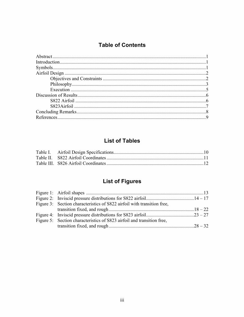
Table of Contents Abstract ................................................................................................................................1 Introduction..........................................................................................................................1 Symbols................................................................................................................................1 Airfoil Design ......................................................................................................................2
Objectives and Constraints ......................................................................................2 Philosophy................................................................................................................3 Execution .................................................................................................................5
Discussion of Results...........................................................................................................6 S822 Airfoil .............................................................................................................6 S823Airfoil ..............................................................................................................7 Concluding Remarks............................................................................................................8 References............................................................................................................................9
List of Tables
Table I. Airfoil Design Specifications...........................................................................10 Table II. S822 Airfoil Coordinates .................................................................................11 Table III. S826 Airfoil Coordinates .................................................................................12
List of Figures
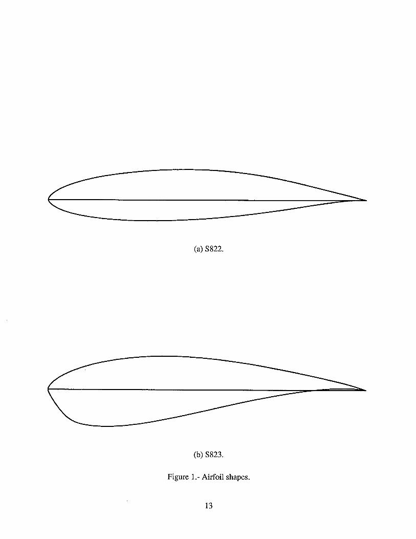
Figure 1: Airfoil shapes ..................................................................................................13 Figure 2: Inviscid pressure distributions for S822 airfoil........................................14 – 17 Figure 3: Section characteristics of S822 airfoil with transition free,
transition fixed, and rough .......................................................................18 – 22 Figure 4: Inviscid pressure distributions for S823 airfoil........................................23 – 27 Figure 5: Section characteristics of S823 airfoil and transition free,
transition fixed, and rough .......................................................................28 – 32
THE S322 AND S823 AIRFOILS
Dan M. Somers
December 1993
ABSTRACT
A family of thick airfoils for 3- to 10-meter, stall-regulated, horizontal-axis wind turbines, the S822 and S823, has been designed and analyzed theoretically. The primary objectives of restrained maximum lift, insensitive to roughness, and low profile drag have been achieved. The constraints on the pitching moments and airfoil thicknesses have been satisfied.
INTRODUCTION
The family of thick airfoils designed under this study is intended for 3- to 10-meter, stall- regulated, horizontal-axis wind turbines. Four earlier thick-airfoil families, the S809, S 8 10, and S811 (ref. l), the S812, S813,5814, and S815 (refs. t and 2), the S816, S817, and S818 (ref. 3), and the S819, S820, and 5821 (ref. 4), were designed for 20- to 30-meter, 20- to 30-meter, 30- to 40-meter, and 10- to 20-meter wind turbines, respectively.
The specific tasks performed under this study are described in National Renewable Energy Laboratory (NREL) Subcontract Number AAO-3- 13023-01- 104879. The specifications for the airfoils are outlined in the Statement of Work. These specifications were later refined during telephone conversations with Mr. James L. Tangler of NREL.
Because of the limitations of the theoretical methods (refs. 5 and 6) employed in this study, the results presented are in no way guaranteed to be accurate-either in an absolute or in a relative sense. This statement applies to the entire study,
SYMBOLS
CP
C
cd
pressure coefficient
airfoil chord, meters
section profile-drag coefficient
C1 section lift coefficient
Cm section pitching-moment coefficient about quarter-chord point
L. lower surface
MU boundary-layer transition mode (ref. 6)
R Reynolds number based on ftee-stream conditions and airfoil chord
S. boundary-layer separation location, 1 - ssep/c
Ssep arc length along which boundary layer is separated, meters
Stub arc length along which boundary layer is turbulent including ssep, meters
T. boundary-layer transition location, 1 - St,b/C
U. upper surface
X airfoil abscissa, meters
Y airfoil ordinate, meters
a angle of attack relative to chord line, degrees
AIRFOIL DESIGN
OBJECTIVES AND CONSTRAINTS
The design specifications for the family of airfoils are contained in table I. The family consists of two airfoils, tip and root, corresponding to the 0.90 and 0.40 blade radial stations, respectively .
Two primary objectives are evident from the specifications. The first objective is to re- strain the maximum lift coefficient of the tip airfoil to the relatively low value of 1 .OO. In contrast, the maximum lift coefficient of the root airfoil should be as high as possible. A requirement related to this objective is that the maximum lift coefficient not decrease with transition fixed near the leading edge on both surfaces, The second objective is to obtain low profile-drag coefficients
2
over the ranges of lift coefficients from 0.2 to 0.8 for the tip airfoil and from 0.4 to 1.0 for the root airfoil.
Two major constraints were placed on the designs of these airfoils. First, the zero-lift pitching-moment coefficients must be no more negative than 4 0 7 for the tip airfoil and -0.15 for the root airfoil. Second, the airfoil thicknesses must equal 16-percent chord for the tip airfoil and 21-percent chord for the root airfoil.
PHILOSOPHY
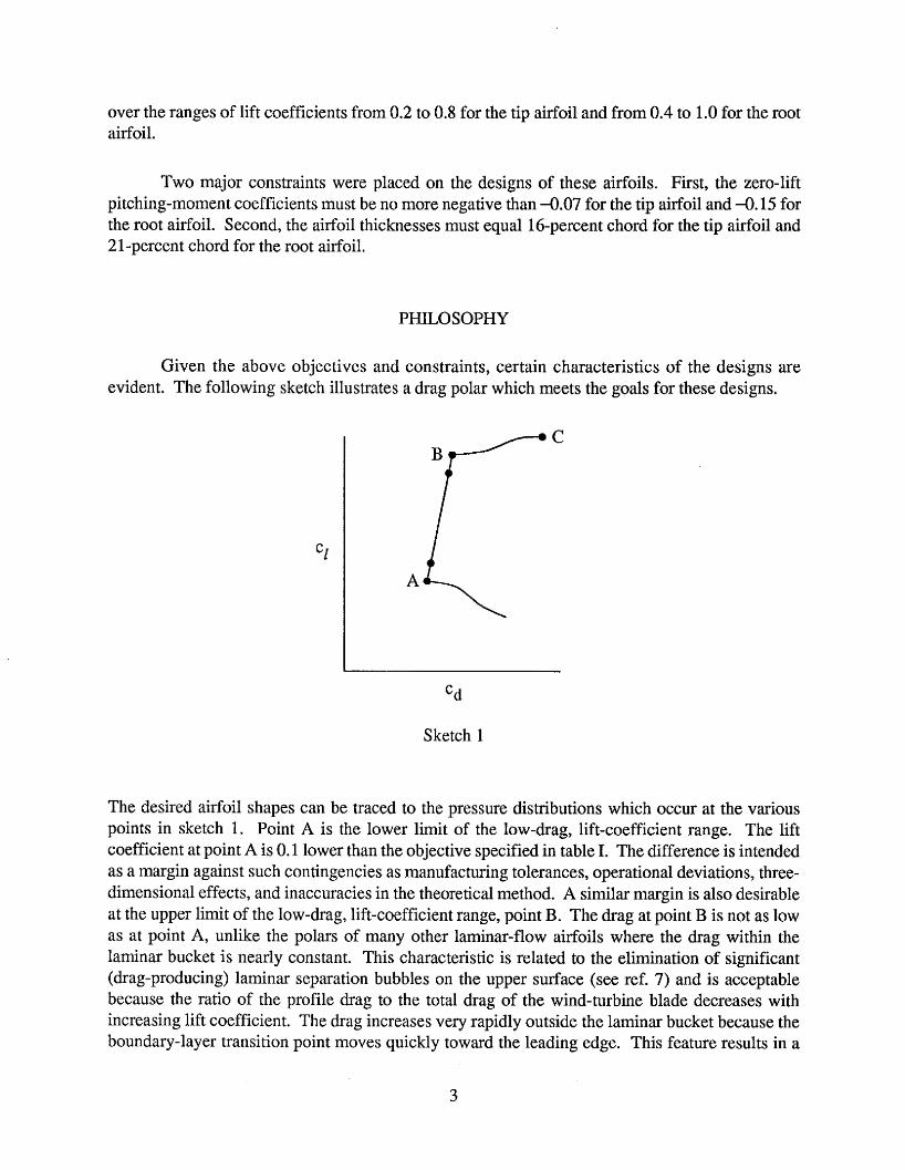
Given the above objectives and constraints, certain characteristics of the designs are evident. The following sketch illustrates a drag polar which meets the goals for these designs.
‘d
Sketch 1
The desired airfoil shapes can be traced to the pressure distributions which occur at the various points in sketch 1. Point A is the lower limit of the low-drag, lift-coefficient range. The lift coefficient at point A is 0.1 lower than the objective specified in table I. The difference is intended as a margin against such contingencies as manufacturing tolerances, operational deviations, three- dimensional effects, and inaccuracies in the theoretical method. A similar margin is also desirable at the upper limit of the low-drag, lift-coefficient range, point B. The drag at point B is not as low as at point A, unlike the polars of many other laminar-flow airfoils where the drag within the laminar bucket is nearly constant. This characteristic is related to the elimination of significant (drag-producing) laminar separation bubbles on the upper surface (see ref. 7) and is acceptable because the ratio of the profile drag to the total drag of the wind-turbine blade decreases with increasing lift coefficient. The drag increases very rapidly outside the laminar bucket because the boundary-layer transition point moves quickly toward the leading edge. This feature results in a
3
rather sharp leading edge which produces a suction peak at higher lift coefficients, which limits the maximum lift coefficient and ensures that transition on the upper surface will occur very near the leading edge. Thus, the maximum lift coefficient occurs with turbulent flow along the entire upper surface and, therefore, should be insensitive to roughness at the leading edge. Point C is the maximum lift coefficient.
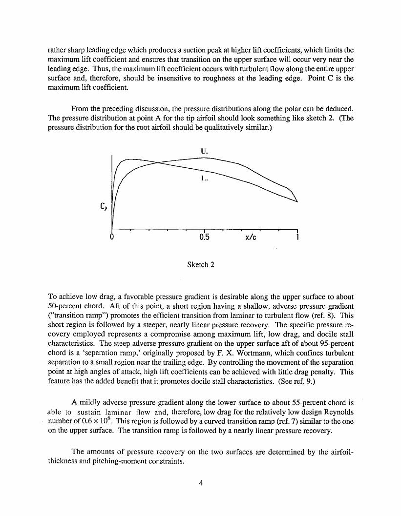
From the preceding discussion, the pressure distributions along the polar can be deduced. The pressure distribution at point A for the tip airfoil should look something like sketch 2. (The pressure distribution for the root airfoil should be qualitatively similar.)
U.
I I
0 0.5 x/c 1 I 1 I I 1 1 I 1 1
Sketch 2
To achieve low drag, a favorable pressure gradient is desirable along the upper surface to about 50-percent chord. Aft of this point, a short region having a shallow, adverse pressure gradient (“transition ramp”) promotes the efficient transition from laminar to turbulent flow (ref. 8). This short region is followed by a steeper, nearly linear pressure recovery. The specific pressure re- covery employed represents a compromise among maximum lift, low drag, and docile stall characteristics. The steep adverse pressure gradient on the upper surface aft of about 95-percent chord is a ‘separation ramp,’ originally proposed by F. X. Wortmann, which confines turbulent separation to a small region near the trailing edge. By controlling the movement of the separation point at high angles of attack, high lift coefficients can be achieved with little drag penalty, This feature has the added benefit that it promotes docile stall characteristics. (See ref. 9.)
A mildly adverse pressure gradient along the lower surface to about 55-percent chord is able to sustain laminar flow and, therefore, low drag for the relatively low design Reynolds number of 0.6 x lo6. This region is followed by a curved transition ramp (ref. 7) similar to the one on the upper surface. The transition ramp is followed by a nearly linear pressure recovery.
The amounts of pressure recovery on the two surfaces are determined by the airfoil- thickness and pi tching-mornen t cons train ts.
4
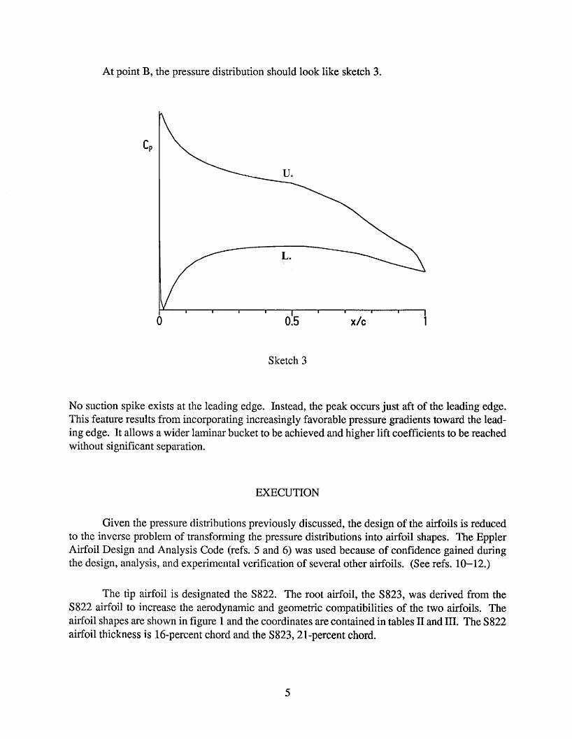
At point By the pressure distribution should look like sketch 3.
Sketch 3
No suction spike exists at the leading edge. Instead, the peak occurs just aft of the leading edge. This feature results from incorporating increasingly favorable pressure gradients toward the lead- ing edge. It allows a wider laminar bucket to be achieved and higher lift coefficients to be reached without significant separation.
EXECUTION
Given the pressure distributions previously discussed, the design of the airfoils is reduced to the inverse problem of transforming the pressure distributions into airfoil shapes. The Eppler Airfoil Design and Analysis Code (refs. 5 and 6) was used because of con€idence gained during the design, analysis, and experimental verification of several other airfoils. (See refs. 10-12.)
The tip airfoil is designated the S822. The root airfoil, the 5823, was derived from the S822 airfoil to increase the aerodynamic and geometric compatibilities of the two airfoils. The airfoil shapes are shown in figure 1 and the coordinates are contained in tables I1 and 111. The S822 airfoil thickness is 16-percent chord and the S823,2Lpercent chord.
5
DISCUSSION OF RESULTS
S 822 AIRFOIL
Pressure Distributions
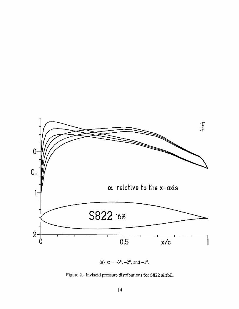
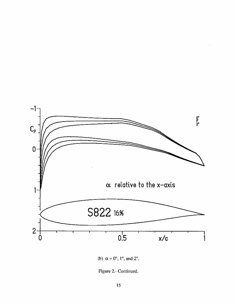
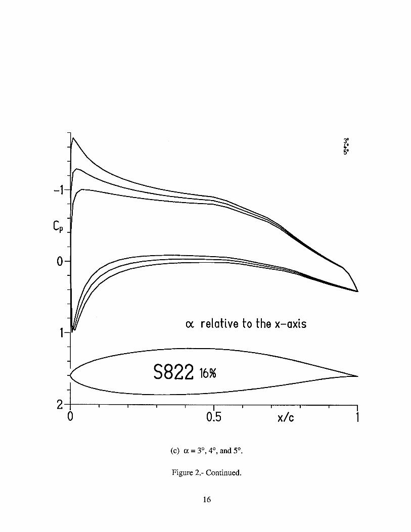
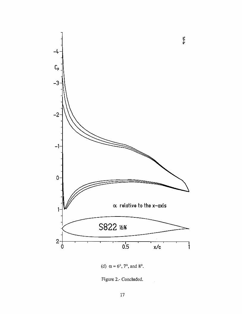
The inviscid (potential-flow) pressure distributions for the S 822 airfoil for various angles of attack are shown in figure 2. Because the free-stream Mach number for all relevant operating conditions remains below 0.2, these and all subsequent results are incompressible.
Transition and Separation Locations
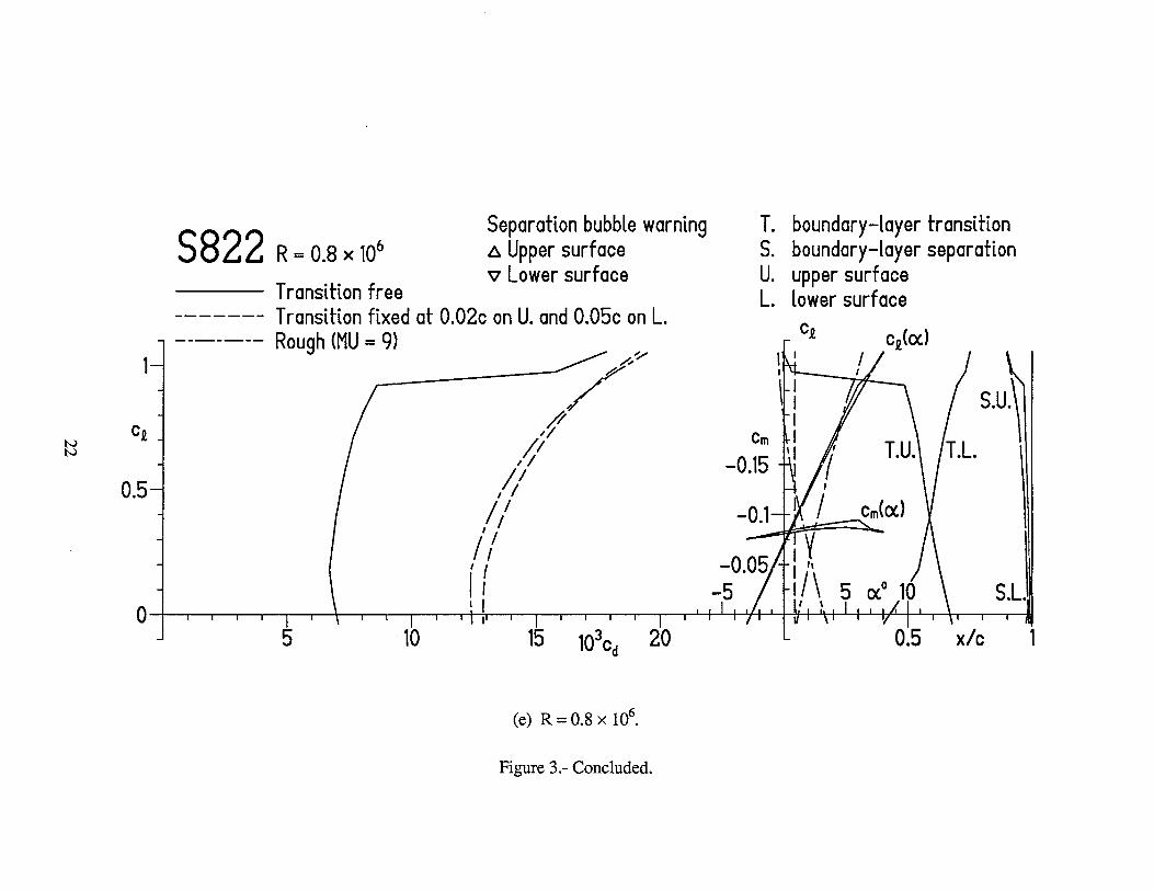
The variation of boundary-layer transition location with lift coefficient for the S822 airfoil is shown in figure 3. It should be remembered that the method of references 5 and 6 ‘defines’ the transition location as the end of the laminar boundary layer whether due to natural transition or laminar separation. Thus, for conditions which result in relatively long laminar separation bubbles (low lift coefficients for the upper surface and high lift coefficients for the lower surface and/or low Reynolds numbers), poor agreement between the predicted ‘transition? locations and the lo- cations measured experimentally can be expected. This poor agreement is worsened by the fact that transition is normally confirmed in the wind tunnel only by the detection of attached turbulent flow. For conditions which result in shorter laminar separation bubbles (high lift coefficients for the upper surface and low lift coefficients for the lower surface and/or high Reynolds numbers), the agreement between theory and experiment should be quite good. (See ref. 13.)
The variation of turbulent boundary-layer separation location with lift coefficient for the 5822 airfoil is shown in figure 3. A small separation is predicted on the upper surface at all lift Coefficients. This separation, which is caused by the separation ramp (fig. 2), increases in length with transition fixed near the leading edge. A small separation is predicted on the lower surface at lift coefficients below about 0.2 with transition fixed. This separation is not considered important because it occurs at lift coefficients which are not typical of normal wind-turbine operations. Also, such separation usually has little effect on the section characteristics. (See ref. 13.)
Section Characteristics
- Reynolds number effects.- The section characteristics of the S822 airfoil are shown in figure 3. It should be noted that the maximum lift coefficient predicted by the method of refer- ences 5 and 6 is not always realistic. Accordingly, an empirical criterion should be applied to the computed results. This criterion assumes that the maximum lift coefficient has been reached if the drag coefficient of the upper surface is greater than 0.0240 or if the length of turbulent separation along the upper surface is greater than 0.10. Thus, the maximum lift coefficient for the design
6
Reynolds number of 0.6 x 10⁶ is predicted to be 1.00, which meets the design objective. Based on the movement of the upper-surface separation point, the stall characteristics are expected to be docile. Low profile-drag coefficients are predicted over the range of lift coefficients from about 0.1 to about 0.9, which exceeds the range specified (0.2 to 0.8). The drag coefficient at the spec- ified lower limit of the laminar bucket (cl = 0.2) is predicted to be 0.0072, which is 28 percent below the design objective. The zero-lift pitching-moment coefficient is predicted to be -0.0779, which exceeds the design constraint. However, the method of references 5 and 6 gener- ally overpredicts the pitching-moment coefficient by about 10 percent. Thus, the actual zero-lift pitching-moment coefficient should be about -0.07, which satisfies the constraint.
An additional analysis (not shown) indicates that significant (drag-producing) laminar separation bubbles should not occur on either surface for any relevant operating condition.
Effect of roughness.- The effect of roughness on the section characteristics of the S822 airfoil is shown in figure 3. Transition was fixed at 2-percent chord on the upper surface and 5-percent chord on the lower surface using transition mode MU = 1 (ref. 6). The maximum lift coefficient is unaffected by fixing transition at these locations because transition on the upper surface is predicted to occur forward of 2-percent chord at the maximum lift coefficient. The ‘rough’ results were obtained using transition mode MU = 9 (ref. 6), which simulates distributed roughness due to, for example, leading-edge contamination by insects or rain. At the higher lift coefficients, this transition mode is probably comparable to National Advisory Committee for Aeronautics (NACA) Standard Roughness which “is considerably more severe than that caused by the usual manufacturing irregularities or deterioration in service” (ref. 14). For the rough condi- tion, the maximum lift coefficient for the design Reynolds number of 0.6 x lo6 is predicted to be 0.98, a reduction of two percent from that for the transition-free condition. Thus, one of the most important design requirements has been achieved. The drag coefficients are, of course, adversely affected by the roughness.
S823 AIRFOIL
Pressure Distributions
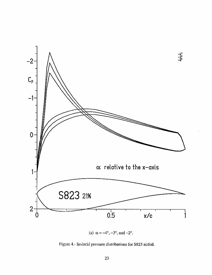
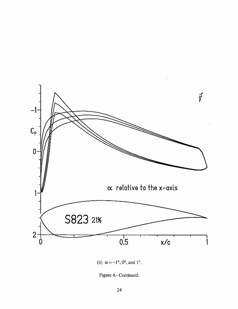
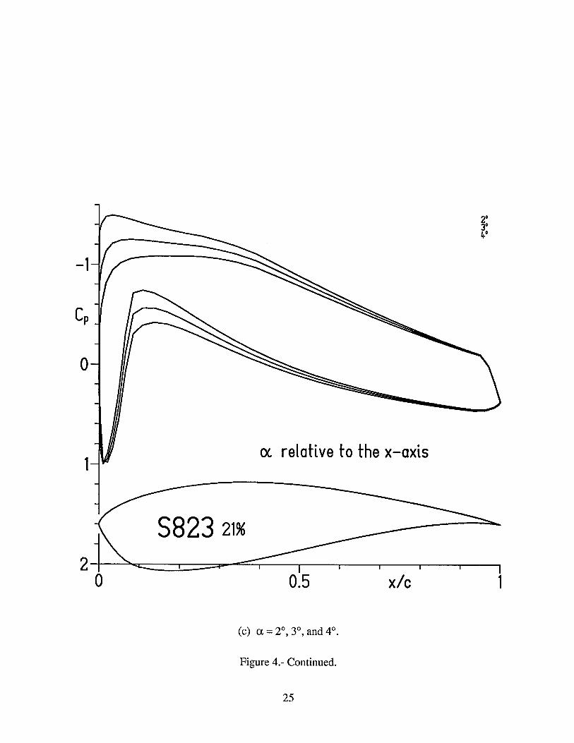
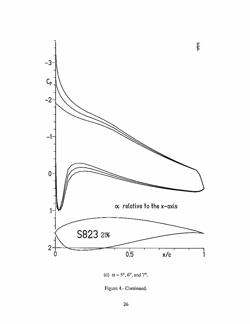
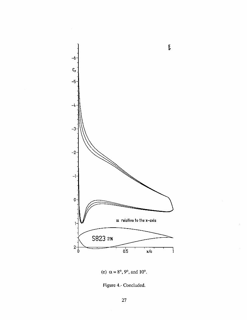
The inviscid (potential-flow) pressure distributions for the S823 airfoil for various angles of attack are shown in figure 4.
Transition and Separation Locations
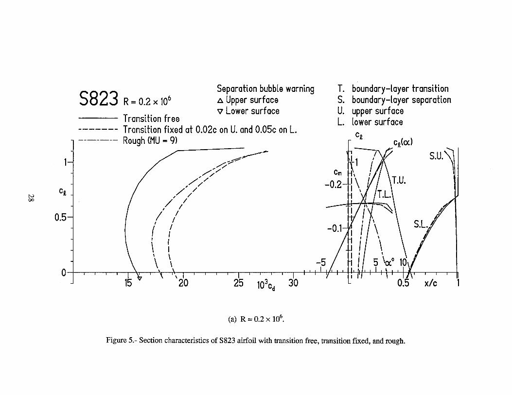
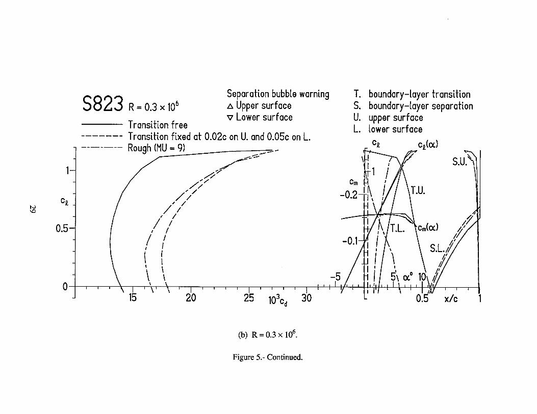
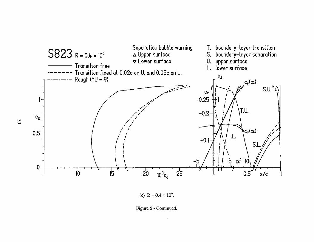
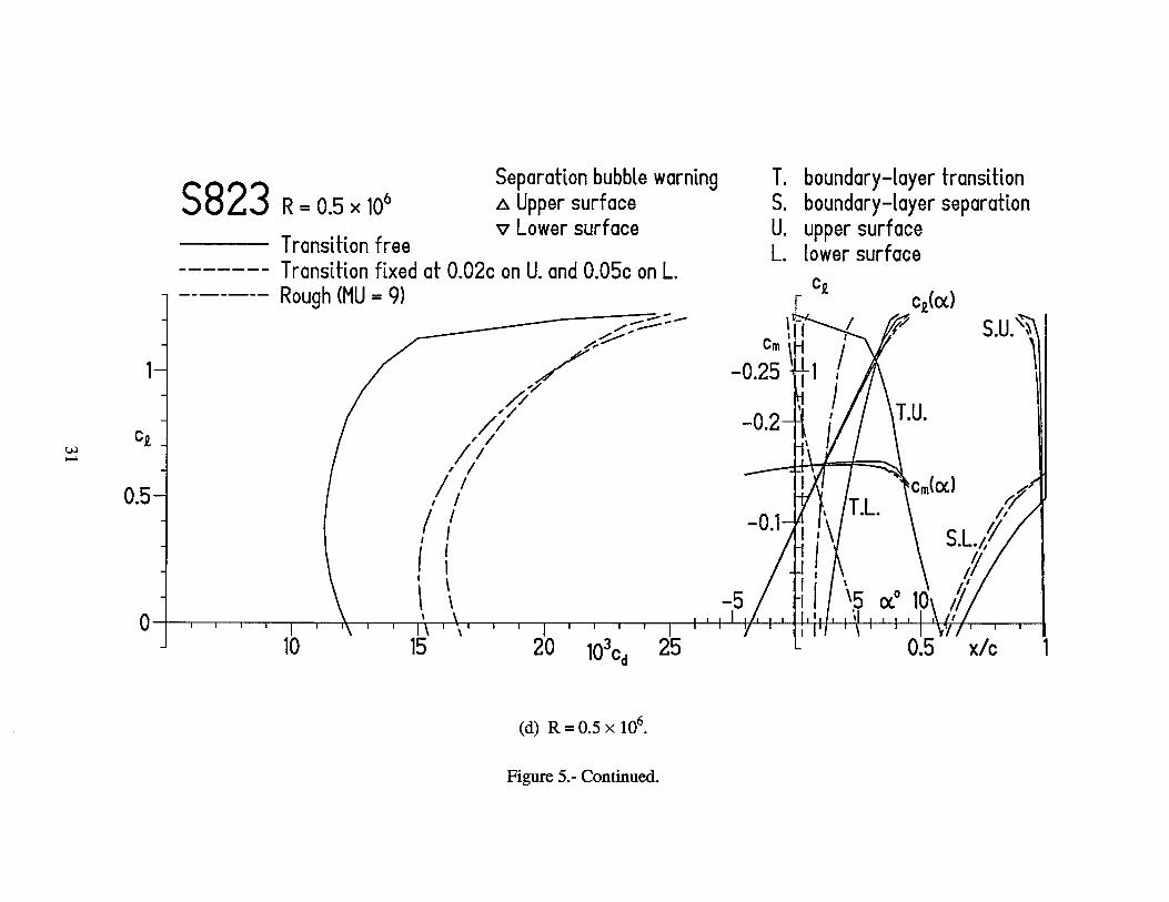
The variations of transition and turbulent-separation locations with lift coefficient for the S823 airfoil are shown in figure 5. A small separation is predicted on the upper surface at all lift coefficients. This separation, which is caused by the separation ramp (fig. 4), increases in length
7
with transition fixed near the leading edge. Separation is predicted on the lower surface at lower lift coefficients. Such separation usually has only a minor effect on the section characteristics.
Section Characteristics
- Reynolds number effects.- The section characteristics of the S823 airfoil are shown in figure 5, Using the previously-described criterion, the maximum lift coefficient for the design Reynolds number of 0.4 x lo6 is predicted to be 1.20, which meets the design objective. The stall characteristics are expected to be docile. Low drag coefficients are predicted over the range of lift coefficients from 0 to about I. 1, which exceeds the range specified (0.4 to 1 .O). The drag coeffi- cient at the specified lower limit of the laminar bucket (q = 0.4) is predicted to be 0.0120, which is 33 percent below the design objective. The zero-lift pitching-moment coefficient is predicted to be -0.1497, which satisfies the design constraint. Again, because the method of references 5 and 6 overpredicts the pitching-moment coefficient, the actual zero-lift pitching-moment coefficient should be about -0.13. Significant (drag-producing) laminar separation bubbles may occur on the lower surface; their effect is expected to be minor.
Effect of roughness.- The effect of roughness on the section characteristics of the S823 airfoil is shown in figure 5. Transition was fixed at 2-percent chord on the upper surface and 5-percent chord on the lower surface using transition mode MU = 1. The maximum lift coefficient is essentially unaffected by fixing transition at these locations because transition on the upper surface is predicted to occur near 2-percent chord at the maximum lift coefficient. For the rough condition (MU = 9), the maximum lift coefficient for the design Reynolds number of 0,4 x lo6 is predicted to be 1.16, a reduction of three percent from that for the transition-free condition. Thus, one of the most important design requirements has been achieved. The drag coefficients are, of course, adversely affected by the roughness.
CONCLUDING REMARKS
A family of thick airfoils for 3- to 10-meter, stall-regulated, horizontal-axis wind turbines, the S822 and S823, has been designed and analyzed theoretically. The primary objectives of restrained maximum lift coefficient, insensitive to roughness, and low profile-drag coefficients have been achieved. The constraints on the pitching-moment coefficients and airfoil thicknesses have been satisfied.
8
REFERENCES
1. Somers, Dan M.: The S809 through S813 Airfoils. Airfoils, Inc., 1988.
2. Somers, Dan M.: The S814 and S815 Airfoils. Airfoils, Inc., 1992.
3. Somers, Dan M.: The S816, S817, and S818 Airfoils. Airfoils, Inc., 1992.
4. Somers, Dan M.: The S819, S820, and S821 Airfoils. Airfoils, Inc., 1993.
5. Eppler, Richard: Airfoil Design and Data. Springer-Verlag (Berlin), 1990.
6. Eppler, R.: Airfoil Program System. User’s Guide. R. Eppler, c.1991.
7. Eppler, Richard; and Somers, Dan M.: Airfoil Design for Reynolds Numbers Between 50,000 and 500,000. Proceedings of the Conference on Low Reynolds Number Airfoil Aerodynam- ics, UNDAS-CP-77B123, Univ. of Notre Dame, June 1985, pp. 1-14.
8. Wortmann, F. X.: Experimental Investigations on New Laminar Profiles for Gliders and Helicopters. TILn.4906, British Minist. Aviat., Mar. 1960. (Translated from Z. Hugwissen- schaften, Bd. 5, Heft 8, Aug. 1957, pp. 228-243.)
9. Maughmer, Mark D.; and Somers, Dan M,: Design and Experimental Results for a High- Altitude, Long-Endurance Airfoil. J. Aircr., vol. 26, no. 2, Feb. 1989, pp. 148-153.
10. Somers, Dan M.: Design and Experimental Results for the S809 Airfoil. Airfoils, Inc., 1989.
11. Somers, Dan M.: Design and Experimental Results for the S805 Airfoil. Airfoils, Inc., 1988.
12. Somers, Dan M.: Subsonic Natural-Laminar-Flow Airfoils. Natural Laminar Flow and Larni- nar Flow Control, R. W. Barnwell and M. Y. Hussaini, eds., Springer-Verlag New York, Inc., 1992, pp. 143-176.
13. Somers, Dan M.: Design and Experimental Results for a Natural-Laminar-Flow Airfoil for General Aviation Applications. NASA TP- 1861, 198 1.
14. Abbott, Ira H.; Von Doenhoff, Albert E.; and Stivers, Louis S., Jr.: Summary of Airfoil Data. NACA Rep. 824, 1945. (Supersedes NACA WR L-560.)
9

Parameter
Airfoil
TABLE I.- AIRFOIL DESIGN SPECIFICATIONS
ObJ ective/Constr aint
Blade radial station
Reynolds number
Maximum lift coefficient
Low-drag, lift-coefficient range:
Lower limit
Upper limit
Minimum profile-drag coefficient
Zero-lift pitc hing-momen t coefficient
Tip
0.90
0.6 x lo6
1 .oo
0.2
0.8
0.0100
2 -0.07
Root
0.40
0.4 x lo6
1.20
0.4
1 .o
0.0 180
2 -0.15
Thickness 0.16~ 0.21c
I
10
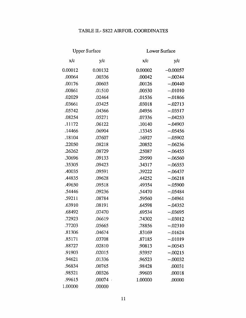
TABLE 11.- S822 AIRFOIL COORDINATES
Upper Surface
X/C
0.000 12 .00064 .00176 .00861 .02029 .03661 .05742 .08254 ,11172 .I4466 .I8104 .22050 ,26262 .30696 .35305 .40035 .44835 .49650 ,54446 .59211 .63910 A8492 ,72923 -77203 A1306 35171 38727 .91903 .94621 .96834 ,98521 .99615
1 .ooooo
Y/C
0.00132 ,00336 .00603 .01510 .02464 .03425 ,04366 .0527 1 .06122 .06904 ,07607 .08218 .08729 .09133 .09423 .0959 1 .09628 .095 18 -09236 .08784 .08 19 1 .07470 .06619 .05665 .04674 .03708 .02810 .02015 -01336 .00765 .00326 .00074 .ooooo
Lower Surface
X/C
0.00002 -00042 ,00126 ,00530 ,01536 .03018 .04956 .07336 .lo140 .13345 .16927 .20852 .25087 .29590 .?4317 .39222 A4252 .49354 .54470 .59560 .64598 .69534 .74302 .78856 33169 +87 185 90813 .93957 .96523 .98428 .99603
1 .00000
Y/C
-0.00057 -.00244 -.00440 -.o 10 10 -.O 1864 -.027 13 -.035 17 -.04253 - .049 0 3 -.05456 -.05902 -.06236 -.06455 -.06560 -.06553 -.06437 -.06218 -.05900 -.05484 -.04961 -.04352 -.03695 -.030 12 -.023 10 -.O 1624 -.01019 -.00543 -.002 15 -.00032
,0003 1 ,000 18 .ooooo
11
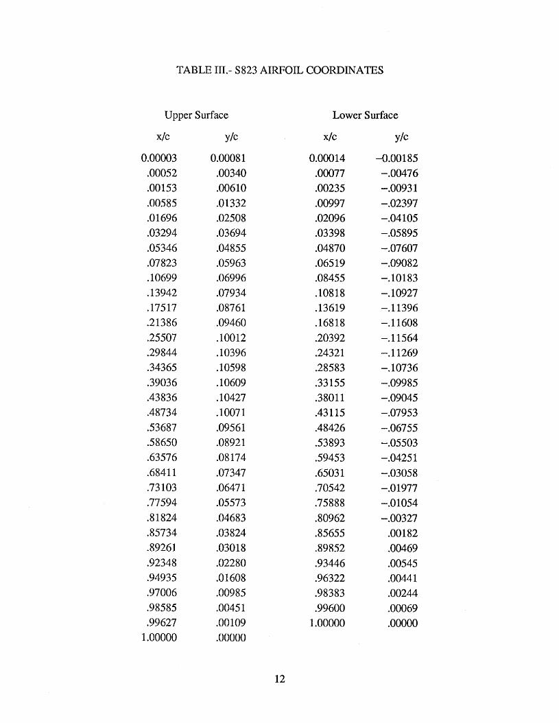
TABLE 111.- S823 AIRFOIL COORDINATES
Upper Surface
x/c
0.00003 .00052 .00153 .00585 .01696 .03294 .05346 .07823 .lo699 ,13942 ,17517 .21386 ,25507 ,29844 ,34365 ,39034 .43836 .48734 .53687 ,58650 ,63576 -6841 1 .73 103 .77594 31824 ,85734 -89261 .92348 .94935 .97006 .98585 ,99627 1 .QOOOO
Y/C
0.0008 1 .00340 .00610 ,01332 ,02508 .03694 .04855 .05963 .06996 ,07934 ,08761 ,09460 .loo12 .I0396 SO598 .lo609 .lo427 ,10071 .09561 .08921 .Of3174 ,07347 .0647 1 .05573 .04683 .03824 .03018 .02280 .OM08 ,00985 .0045 1 .OO 109 .ooooo
Lower Surface
X/C
0.000 14 .00077 .00235 ,00997 ,02096 .03398 .04870 .045 19 .Of3455 ,10818 ,13619 ,16818 .20392 .24321 .28583 .33 155 ,38011 .43115 .48426 .53893 .59453 A503 1 .70542 .75888 .go962 35655 39852 .93446 .96322 .98383 .99600 1 .ooooo
Y/C
-0.00 185 -.00476 -+0093 1 -.02397 -.04 105 -.05895 -.07607 -.09082 -.lo183 -. 10927 -. 1 1396 -. 1 1608 -.11564 -. 11269 -. 10736 -.09985 -.(I9045 -.07953 -.06755 -.05503 -.0425 1 -.03058 -.O 1977 -.O 1054 -.00327
.OO 182
.00469
.00545
.00441
.00244
.00069
.ooooo
12


F1147-E(05/2004)
REPORT DOCUMENTATION PAGE Form Approved OMB No. 0704-0188
The public reporting burden for this collection of information is estimated to average 1 hour per response, including the time for reviewing instructions, searching existing data sources, gathering and maintaining the data needed, and completing and reviewing the collection of information. Send comments regarding this burden estimate or any other aspect of this collection of information, including suggestions for reducing the burden, to Department of Defense, Executive Services and Communications Directorate (0704-0188). Respondents should be aware that notwithstanding any other provision of law, no person shall be subject to any penalty for failing to comply with a collection of information if it does not display a currently valid OMB control number. PLEASE DO NOT RETURN YOUR FORM TO THE ABOVE ORGANIZATION. 1. REPORT DATE (DD-MM-YYYY)
January 2005 2. REPORT TYPE
Subcontract report 3. DATES COVERED (From - To)
October 1992 – December 1993 5a. CONTRACT NUMBER
DE-AC36-99-GO10337
5b. GRANT NUMBER
4. TITLE AND SUBTITLE The S822 and S823 Airfoils
5c. PROGRAM ELEMENT NUMBER
5d. PROJECT NUMBER NREL/SR-500-36342
5e. TASK NUMBER WER4.3110
6. AUTHOR(S) D.M. Somers
5f. WORK UNIT NUMBER
7. PERFORMING ORGANIZATION NAME(S) AND ADDRESS(ES) Airfoils, Inc. 601 Cricklewood Drive State College, PA 16083
8. PERFORMING ORGANIZATION REPORT NUMBER AAO-3-13023-01-104879
10. SPONSOR/MONITOR'S ACRONYM(S) NREL
9. SPONSORING/MONITORING AGENCY NAME(S) AND ADDRESS(ES) National Renewable Energy Laboratory 1617 Cole Blvd. Golden, CO 80401-3393 11. SPONSORING/MONITORING
AGENCY REPORT NUMBER NREL/SR-500-36342
12. DISTRIBUTION AVAILABILITY STATEMENT National Technical Information Service U.S. Department of Commerce 5285 Port Royal Road Springfield, VA 22161
13. SUPPLEMENTARY NOTES NREL Technical Monitor: J. Tangler
14. ABSTRACT (Maximum 200 Words) A family of thick airfoils for 3- to 10-meter, stall-regulated, horizontal-axis wind turbines, the S822 and S823, has been designed and analyzed theoretically. The primary objectives of restrained maximum lift, insensitive to roughness, and low profile have been achieved. The constraints on the pitching moments and airfoil thicknesses have been satisfied.
15. SUBJECT TERMS airfoils; wind turbine; airfoil design; Pennsylvania State University; wind energy
16. SECURITY CLASSIFICATION OF: 19a. NAME OF RESPONSIBLE PERSON a. REPORT
Unclassified b. ABSTRACT Unclassified
c. THIS PAGE Unclassified
17. LIMITATION OF ABSTRACT
UL
18. NUMBER OF PAGES
19b. TELEPONE NUMBER (Include area code)
Standard Form 298 (Rev. 8/98) Prescribed by ANSI Std. Z39.18