the phoenix gps receiver - a practical example of the
TRANSCRIPT

The Phoenix GPS Receiver - A Practical Example of the
Successful Application of a COTS-Based Navigation Sensor in
Different Space Missions
M. Markgraf ([email protected])
DLR/GSOC, Oberpfaffenhofen, D-82230 Wessling, Germany
> WiSEE / REWA > M. Markgraf • Phoenix GPS > 12.10.2020DLR.de • Chart 1

Content
▪ Background and Motivation
▪ Phoenix GPS Receiver
▪ Qualification and Test Program
▪ Environmental Testing
▪ Vibration & Shock
▪ Thermal-Vacuum
▪ Radiation
▪ Performance Testing
▪ Flight Heritage
▪ Proba-2 Mission
▪ Overview and GPS System Architecture
▪ Flight Result
▪ Radiation Effects
▪ Summary and Conclusions
> WiSEE / REWA > M. Markgraf • Phoenix GPS > 12.10.2020DLR.de • Chart 2

Background and Motivation
• GPS has become a „standard“ sensor in almost every space mission over the last two decades
• Fully space-qualified GNSS receivers are expansive (>1M€) - unaffordable for many projects due to limited
budgets
• COTS-based GPS receivers are typically the only alternative for such missions
• However, use of COTS-based technology requires thorough testing and good understanding
of reliability and failure mechanisms
• DLR designs, builds and operates satellites and sounding rockets
• Strong in-house need for affordable GPS/GNSS technology
• DLR’s Space Flight Technology group commenced to explore, develop, and test COTS-based GPS
receiver in the late 1990s.
• Phoenix GPS receiver for space missions as an outcome of these works
> WiSEE / REWA > M. Markgraf • Phoenix GPS > 12.10.2020DLR.de • Chart 3

Phoenix GPS Receiver - Hardware
• 12 channel L1 single-frequency receiver for high-dynamics
applications
• Entirely based on COTS technology
• Commercial H/W platform (SigTec MG5001)
• Ca. 70 x 47 x 11 mm3
• Mass < 25 g
• Power Consumption 0.7-0.9 W
• Only minor modifications required for use onboard rockets
and satellites (battery, connectors)
> WiSEE / REWA > M. Markgraf • Phoenix GPS > 12.10.2020DLR.de • Chart 4
75mm
50mm
Mass: <25g
Top side of the Phoenix GPS receiver board
Self-contained GPS unit developed for Eu:CROPIS satellite mission
• Additional I/F electronic requires
(Power and signal conditioning,
latch-up protection, etc.)

Phoenix GPS Receiver - Firmware
• Originates from sample source code of an earlier available GPS development kit
• Received extensive revision and enhancements
• Added Carrier tracking
• Carrier phase smoothing (reduced position noise)
• Range-rate from carrier phase (accurate velocity)
• Advanced tracking loops for robust tracking under high signal dynamics
• Flexible TM/TC interface
• Integer second synchronization and 1PPS signal
• Hot start capability (30s)
• Non-volatile memory and real-time clock
• Aiding with twoline elements
• Available in two versions:
• Phoenix-HD for high dynamic applications (launchers and rockets)
• Phoenix-S for LEO satellites
> WiSEE / REWA > M. Markgraf • Phoenix GPS > 12.10.2020DLR.de • Chart 5

Environmental Testing – Vibration & Shock
• Tests conducted for wide
range of load profiles
(Soyuz, Ariane-5, Vega…)
• On Sub-system or system
level
• Operational mode
• Stimulation of receiver
with signals from a GNSS
signal simulator
• Study of impact of
vibration onto tracking and
navigation behavior
> WiSEE / REWA > M. Markgraf • Phoenix GPS > 12.10.2020DLR.de • Chart 6

Environmental Testing – Thermal-Vacuum
• Test conducted at DLR’s own test
facilities at Oberpfaffenhofen in close
accord with ECSS testing standards
• Atmospheric pressure as well as vacuum
conditions
• Thermal cycling in operational and
passive mode
• Temperature range: • -30° to +70° operational
• -40° and +80° non-operational (storage)
• Increase of power consumption at higher
temperatures (ca. +8%/100K)
• No impact on navigation performance
> WiSEE / REWA > M. Markgraf • Phoenix GPS > 12.10.2020DLR.de • Chart 7

Radiation Tests – TID (I)
> WiSEE / REWA > M. Markgraf • Phoenix GPS > 12.10.2020DLR.de • Chart 8
Outside
antenna
ca. 15m
R/F
Test receiver
60Co source
Gammamat
TK1000
20m
(R/F, DC)
20m
(R/F+DC)
Reference
receiver
I/F
board
RS232
ca. 20m
Reg.
power
supply
ca. 2.5m
Power
divider
(-3dB)
Ampere-
meter
Laptop Laptop
RS232
DC block
DC block
ca. 15m
24V DC
LNA
28.7m R/F
cable
Attenuator
-3 dB
HP Computer
(Current/time)
Power
supply
• Total Ionizing Dose (TID) test using Co-60
source
• Conducted at Fraunhofer Institute for
Technological Trend Analysis (FhG/INT) at
Euskirchen, Germany
• Hardware-in-the-loop test setup
• Live GPS signals via roof-top antenna
• Reference receiver operated outside test
chamber
• Direct comparison of navigation solution
and raw data
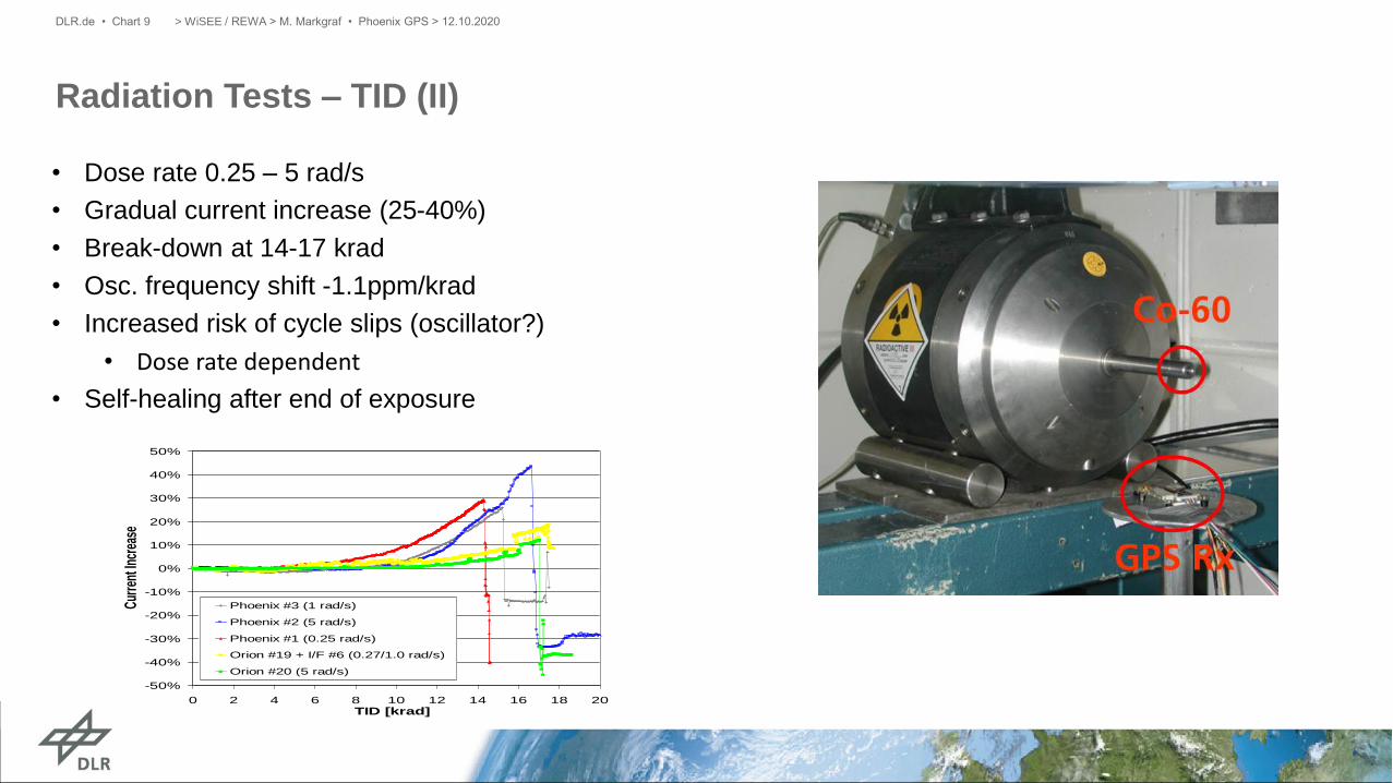
Radiation Tests – TID (II)
> WiSEE / REWA > M. Markgraf • Phoenix GPS > 12.10.2020DLR.de • Chart 9
• Dose rate 0.25 – 5 rad/s
• Gradual current increase (25-40%)
• Break-down at 14-17 krad
• Osc. frequency shift -1.1ppm/krad
• Increased risk of cycle slips (oscillator?)
• Dose rate dependent
• Self-healing after end of exposure
-50%
-40%
-30%
-20%
-10%
0%
10%
20%
30%
40%
50%
0 2 4 6 8 10 12 14 16 18 20TID [krad]
Curr
ent I
ncre
ase
Phoenix #3 (1 rad/s)
Phoenix #2 (5 rad/s)
Phoenix #1 (0.25 rad/s)
Orion #19 + I/F #6 (0.27/1.0 rad/s)
Orion #20 (5 rad/s)

Radiation Tests - Single Event Effect (I)
• SEE Proton characterization performed:
• at the JULIC proton cyclotron of the Research Center
Jülich, Germany (together with Fraunhofer-INT)
• at the Paul Scherrer Institute (PSI) in Villigen,
Switzerland (together with ESA/ESTEC)
• Key objectives of the test campaign were:
• Verify anomalies observed in previous satellite missions
• Identify sensitive component(s)
• Characterize nature of the anomalies and assess
usability of the receiver for future space missions
• All tests performed on board level.
• Test boards connected to GPS signal simulator
> WiSEE / REWA > M. Markgraf • Phoenix GPS > 12.10.2020DLR.de • Chart 10
I/F-Board
Test chamber Control room
Oscilloscope
Phoenix EGSE
(TTL<->RS232)
Spirent GPS Simulator
DC Power Supply
Power Control Box
GPS Data Logging
Oscilloscope Data Logging
+5V DC
Ethernet (~20m)
Serial Cable (~25m)
Rx,Tx (LVTTL)
Current
Probe
+5V &
-15V DC
Proton
Beam
Test setup used for the proton radiation tests conducted with the Phoenix GPS receiver

Radiation Tests - Single Event Effect (II)
• Two different versions of Phoenix boards tested• Only difference in size of SRAM chip
• Broad beam irradiation of entire board
• Narrow beam irradiation of different regions
• Receiver generally sensitive to SELs
• Latch-ups were found to be non-destructive
• SRAM chip identified as radiation-critical component
• SEL rate estimation performed for Proba-2 orbit
(near-circular, sun-synchronous, 725 km altitude)• 0.01 /device/day for “standard” SRAM
• 0.1 /device/day for extended SRAM
• No SEUs observed (probably due to “masking” by
SELs)
> WiSEE / REWA > M. Markgraf • Phoenix GPS > 12.10.2020DLR.de • Chart 11

Performance Assessment
• Hardware-in-the-loop test bed
• Use of a GNSS signal simulator (constellation simulator)
• Simulation of the R/F signals as seen by a receiver
onboard a space vehicle
• Assessment of:• Acquisition and tracking performance
• Navigation accuracy
• Raw data accuracy
> WiSEE / REWA > M. Markgraf • Phoenix GPS > 12.10.2020DLR.de • Chart 12
0.0
0.1
0.2
0.3
0.4
0.5
0.6
0.7
0.8
0.9
1.0
1.1
1.2
1.3
1.4
1.5
35 36 37 38 39 40 41 42 43 44 45 46 47 48 49 50
C/N0 [dB-Hz]
Mea
sure
men
t Noi
se
Pseudorange [m]
Carrier Phase [mm]
Doppler [m/s]

Phoenix GPS – Flight Heritage
> WiSEE / REWA > M. Markgraf • Phoenix GPS > 12.10.2020DLR.de • Chart 13
LEO Satellites
Mission/Project Launch Date Purpose
Proba-2 (ESA) 11/2009 - today orbit determination, flight dynamic
services, time synchronization
Proba-V (ESA) 5/2013 - today orbit determination, flight dynamic
services, time synchronization
Prisma (SSC) 06/2010 – (status
unknown)
orbit determination, time
synchronization, autonomous orbit and
formation control
TET-1 (DLR) 07/2012 - 2019 orbit determination, flight dynamic
services, time synchronization
BIROS/BEESAT-4
(DLR & TU Berlin)
06/2016 - 2019 orbit determination, flight dynamic
services, time synchronization, formation
flying
EuCROPIS (DLR) 12/2018 - 2020 orbit determination, flight dynamic
services, time synchronization
Sounding Rockets
Mission/Project Launch Date Purpose
Texus 39 – 56
(ESA/DLR)
2001 - today Flight safety, recovery, trajectory
determination, time-synchronization
Maxus 4 – 9 (ESA) 2001 - 2017 Flight safety, recovery, trajectory
determination, time-synchronization, GNC
Rexus 4 – 26
(DLR/SSC)
2008 - today Flight safety, recovery, trajectory
determination, time-synchronization
Shefex-I & -II (DLR) 2005 & 2012 Flight safety, recovery, trajectory
determination, time-synchronization, GNC
WADIS 1 & 2 (DLR) 2013 & 2015 Flight safety, recovery, trajectory
determination, time-synchronization,
experiment support
MaxiDusty 1 & 2
(DLR/ASC)
2016 Flight safety, recovery, trajectory
determination, time-synchronization
(flight validation of a new rocket motor)
Launch Vehicles
Ariane-V (VA 219)
(ESA & OHB)
2014 Technology demonstration, Flight
experiment, trajectory determination
Non-exhaustive list of missions and projects using Phoenix GPS receiver

Proba-2 Mission
• Second spacecraft in ESA’s PRoject for OnBoard Autonomy
• Micro-satellite platform for technology demonstration and science:
• Scientific goals: Sun observation and study of space environment
• Novel technology components: Sun and star sensors, two GPS receivers,
propulsion and power system components,
data handling system, etc…
• Built by QinetiQ Space Technology
• Launched 2nd Nov. 2009 01:50 UTC from Plesetsk onboard Rockot
• Sun-synchronous dusk-dawn orbit at approx. 725 km altitude
> WiSEE / REWA > M. Markgraf • Phoenix GPS > 12.10.2020DLR.de • Chart 14

Proba-2 - GPS System Architecture
• Cold redundant system
• Phoenix receivers integrated in AOCS Interface boxes
• Power conditioning
• Line drivers
• Latch-up protection
• Common antenna, but independent LNAs
• Independent measurements from prototype Topstar3000G2
receiver (by Alcatel)
• Laser Retro Reflector
> WiSEE / REWA > M. Markgraf • Phoenix GPS > 12.10.2020DLR.de • Chart 15

Proba-2 – Flight Results
Acquisition and Tracking
• Typical Times-To-First-Fix in standard Sun
pointing attitude mode :• Cold-start: 5..15 min
• Assisted boot: < 2 min
• On average 9 GPS satellites tracked
• 3D rms position accuracy of ~2 m (with peak
errors up to 10m)
> WiSEE / REWA > M. Markgraf • Phoenix GPS > 12.10.2020DLR.de • Chart 16
Navigation Accuracy
• 3D rms navigation accuracy of about • 2 m pos • 5 cm/s vel
• Peak errors up to 10m

Proba-2 – Radiation Effects (I)
• Numerous SELs in almost regular
intervals from beginning of operation
• In average one to two latch-up events
every 48 hours
• Majority of latch-ups can be associated
with the South Atlantic Anomaly
• Remaining events occurred at high
latitudes in the North and South Pole
region
• Also SEUs observed but less frequent
• Both receivers onboard Proba-2 still
performing nominal (almost 11 years in
orbit!!)
> WiSEE / REWA > M. Markgraf • Phoenix GPS > 12.10.2020DLR.de • Chart 17
Geographic distribution of Phoenix-XNS latch-up events on PROBA-2 (September 2010–August 2011)

Proba-2 – Radiation Effects (II)
Statistical analysis of the times between two subsequent latch-up events (2009-2019).
> WiSEE / REWA > M. Markgraf • Phoenix GPS > 12.10.2020DLR.de • Chart 18
Summary and Conclusions
• The Phoenix GPS receiver has been developed as an affordable alternative to fully space qualified
GPS/GNSS receivers.
• A test and qualification program has been conducted with the receiver to ensure a proper operation in space.
• During these tests a relatively high sensitivity to space radiation has been detected (mainly SEL).
• Latch-ups were found to be non-destructive.
• Receiver successfully flying in orbit onboard numerous LEO satellite (11 years abord PROBA-2!!)
• This example demonstrates that COTS electronics can be an alternative to expensive space-qualified
hardware.
• However, environmental testing is essential!
• One should not underestimate the costs and effort associated with the qualification of a COTS system for
space use.
> WiSEE / REWA > M. Markgraf • Phoenix GPS > 12.10.2020DLR.de • Chart 19