the optical analysis of photoemission - nasa optical analysis of photoemission by stephen v. pepper...
TRANSCRIPT

I" COPY: RETURN TQB AFWL (WIfoL)
K I R T " D AFB, N M E X
THE OPTICAL ANALYSIS OF PHOTOEMISSION
by Stephen V. Pepper Lewis Research Center ... , .dg, ,
t
i t I ) Cleveland, Ohio i ' 1
i " - I
N A T I O N A L A E R O N A U T I C S A N D SPACE A D M I N I S T R A T I O N W A S H I N G T O N , D . C. 0 J A N U A R Y 1970
https://ntrs.nasa.gov/search.jsp?R=19700007101 2019-03-16T03:16:49+00:00Z

TECH LIBRARY KAFB, NM
19. Secur i ty C lass i f . ( o f t h i s report)
Unclassified
I111111 11111 11111 lllll lllll11111 IIIII Ill1 1111
20. Secur i ty C loss i f . (of t h i s page) 21. No. o f Pages 22. P r i
Unclassified I 23 1 $3
0332403
1. Report No. 2. Government Access ion No. 1 NASA TN D-5610 4. T i t l e and Subt i t le
THE OPTICAL ANALYSIS OF PHOTOEMISSION
7. Authods)
Stephen V. Pepper
Lewis Resea rch Center National Aeronautics and Space Administration Cleveland, Ohio 44135
9. Performing Organizot ion Name ond Address
12. Sponsoring Agency Name ond Address
National Aeronautics and Space Administration Washington, D. C. 20546
3. Rec ip ien t ' s Catalog No.
5. Report Date
January 1970 6. Performing Orgonizot ion Co
8. Performing Organizat ion Re I E-5321
I 124-09 10. Work U n i t No.
11. Contract or Gront No.
13. Type o f Report and P e r i o d
Technical Note
~~
14. Sponsoring Agency Code
15. Supplementory Notes
16. Abstract
The ro l e of c lass ical optics in the p rocess of photoemission is analyzed. Rigorou p res s ions are obtained for the quantum yield of a uniaxially anisotropic thin fi lm f a rb i t r a ry values of angle of incidence, f i lm thickness and optical constants of the Some applications t o emission f r o m metal f i lms are discussed.
117. K e y Words ( S u g g e s t e d b y A u t h o r ( s ) ) 18. D is t r ibu t ion Statement
Unclassified - unlimited
*For sale by the Clearinghouse for Fede ra l Scientific and Technical Information Springfield, Virginia 22151

THE OPTICAL ANALYSIS OF PHOTOEMISSION
by Stephen V. Pepper
Lewis Research Center
SUMMARY
An analysis of the role of classical optics in the process of photoemission from thin films is presented. The generation of excited electrons throughout the film is assumed to be proportional to the divergence of the Poynting vector in the film. The film and substrate a r e allowed uniaxial optical anisotropy with the optic axis normal to the plane of the film. The main results of the analysis, expressions for the reflectance, trans- mittance, and divergence of the Poynting vector in the film, are valid for all angles of incidence and arbitrary values of the dielectric functions of the initial medium, film, and substrate. Expressions for the quantum yield a re obtained with the aid of a simple function that describes the diffusion and escape of the excited electrons. Some applica- tions to photoemission from metals in the vacuum ultraviolet region a r e discussed.
INTROD UCTl ON
It is now generally accepted that photoemission of electrons is a volumetric process. Electrons a r e excited in the solid beneath the irradiated surface and then diffuse to the surface, where some of them have sufficient energy to penetrate the potential barr ier and escape. The electrons a re emitted from either the irradiated surface o r the one opposite to it in the case of a film type of emitter.
Since the electrons are excited by the electromagnetic field in the interior of the solid, a description of the absorption of the field is necessary for any quantitative theory of photoemission. The analysis of the absorption of the fields in the interior of the emitter constitutes the optical analysis of photoemission. dent on an optically thin film, the optical analysis can be rather complicated. ample, the presence of multiple reflections and standing waves in the interior of the film can cause wide departures from simple exponential decay of the fields. An optical anal- ysis for thin films was discussed by Fry (ref. 1) almost 40 years ago in connection with the work of Ives and Briggs (ref. 2) on photoemission from thin films of the alkali met- als. In this early work, Fry gave a complicated prescription for obtaining an approxi- mate value for the energy density of the electromagnetic field at any point in the interior
For radiation obliquely inci- For ex-
of a metal (ref. 3) and the absorptance of thin metal films. The analysis of photoemission from thin films, however, requires an analysis of the
absorption of radiation throughout the interior of the film, and in this respect Fry's analysis is incomplete. Since there has recently been a revival of interest in photoemis- sion from thin films, it is desirable to have a complete optical analysis available. This report presents a useful and rigorous optical analysis of photoemission from thin films for arbitrary angles of incidence and arbitrary values of the dielectric functions of the incident medium, photoemitter, and substrate. All multiple reflections of waves in the interior of the film are taken into account and wave interference is treated. The main results of the analysis - expressions for the absorption of radiation throughout the film - have the virtue that, besides being mathematically rigorous (within the domain of classi- cal optics), all the te rms have a direct physical interpretation.
with the optic axis normal to the plane of the film. Thus, the results of the analysis may be useful in the study of epitaxial films and optically anisotropic single crystals. Since expressions for the reflectance and transmittance of anisotropic films are not gen- erally known, they a r e also presented.
The diffusion and escape aspects of the photoemission analysis a r e treated by a simple model attributable to Spicer (refs. 4 and 5). tical analysis, is sufficient to serve as a phenomenological framework for the analysis of most photoemission experiments.
First, the photoemission process is formulated in precise te rms and rigorous opti- cal formulas a r e derived. Then, a specific example illustrating the utility of the optical formulation is discussed briefly.
The photoemitting medium and its substrate are allowed uniaxial optical anisotropy
Such a model, together with the op-
FORMULATION OF THE MODEL
Consider first the excitation of electrons. The basic assumption made herein is that the number of electrons excited at any point in the solid is proportional to the num- ber of photons absorbed per unit volume at that point. Denote the number of photons ab- sorbed per unit volume at any point in the photoemitter divided by the number of photons incident per unit a rea of the irradiated surface as q. The quantity q is equal to the ratio of the negative of the divergence of the Poynting vector of the electromagnetic field in the photoemitter to the incident flux.
determined by only classical electromagnetic considerations. The negative sign is nec- essary because the divergence of the Poynting vector yields the energy flux out of a unit volume whereas q is defined as the flux into a unit volume. The function q is a purely
The quantum mechanical factor ii iw is divided out in the ratio of fluxes, and q is
2

- - . . . . ... . -...__, .. .
optical quantity that contains all the optical information necessary for the photoemission analysis, and explicit expressions will be obtained for it.
the passage of the electrons from the point of excitation to the emitting surface. Since the purpose herein is to elucidate only the optics of photoemission, an elementary model (refs. 4 and 5) of the transport and escape processes will be used. Although the model is elementary, it has nevertheless proved quite capable of describing most features of the transport of excited electrons in solids and is widely used. For more detail in this area, the articles by Berglund and Spicer (ref. 6 ) should be consulted.
will reach the surface and enter the collecting medium is denoted by C exp(-y/L). The electron "attenuation length" or "escape depth" L is independent of y but depends on the energy of the photon and the different physical mechanisms that can deexcite the electron. Such mechanisms are, for example, inelastic collisions with photons and other electrons. The factor C is a lumped parameter that takes into account the prob- ability of excitation of the electron into energy states above the vacuum level and the probability of penetration of the surface potential barrier. In principle, L and C may depend on the direction of the electric field at the point of excitation. Such "vectorial" effects are not considered here, since in most situations the direction of the electron is randomized soon after excitation. The elementary diffusion model thus assumes that the mean free path for randomizing collisions is small relative to the thickness of the film. For the present purposes both L and C will be regarded simply as empirical constants which characterize the behavior of excited electrons in a particular solid for a given in- cident photon energy.
face of a film of thickness d is then given by integration over the depth of the film:
The expressions to be obtained for q may be used with any theory that describes
The probability that an electron excited at a depth y below the irradiated surface
The number of electrons emitted per incident photon Y from the illuminated sur -
Y = C Jd q(y)dy = CF(L)
The quantity Y is usually known as the quantum yield. The function F depends on the nonoptical part of the photoemission process only through the attenuation length L.
For emission from the surface opposite to that being illuminated, the quantum yield is
d Y = C [ e-(d-y)/L q(y)dy = C e -d/L F'(L)
3
Obviously F'(L) = F(-L) and only one function F(L) needs to be calculated. Note, how- ever, that since C is characteristic of a given interface, emission into the final me- dium generally requires a different C than emission into the initial medium.
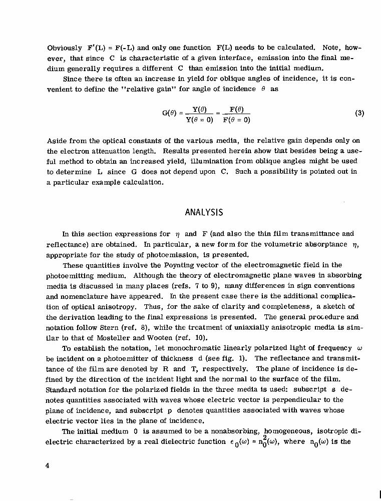
Since there is often an increase in yield for oblique angles of incidence, it is con- venient to define the "relative gain" for angle of incidence 6' as
Aside from the optical constants of the various media, the relative gain depends only on the electron attenuation length. Results presented herein show that besides being a use- ful method to obtain an increased yield, illumination from oblique angles might be used to determine L since G does not depend upon C. Such a possibility is pointed out in a particular example calculation.
ANALYSIS
In this section expressions for q and F (and also the thin film transmittance and reflectance) are obtained. In particular, a new form for the volumetric absorptance q, appropriate for the study of photoemission, is presented.
These quantities involve the Poynting vector of the electromagnetic field in the photoemitting medium. Although the theory of electromagnetic plane waves in absorbing media is discussed in many places (refs. 7 to 9), many differences in sign conventions and nomenclature have appeared. In the present case there is the additional complica- tion of optical anisotropy. Thus, for the sake of clarity and completeness, a sketch of the derivation leading to the final expressions is presented. notation follow Stern (ref. 8), while the treatment of uniaxially anisotropic media is sim- ilar to that of Mosteller and Wooten (ref. 10).
To establish the notation, let monochromatic linearly polarized light of frequency w be incident on a photoemitter of thickness d (see fig. 1). The reflectance and transmit- tance of the film are denoted by R and T, respectively. The plane of incidence is de- fined by the direction of the incident light and the normal to the surface of the film. Standard notation for the polarized fields in the three media is used: subscript s de- notes quantities associated with waves whose electric vector is perpendicular to the plane of incidence, and subscript p denotes quantities associated with waves whose electric vector lies in the plane of incidence.
electric characterized by a real dielectric function E ,(w) = no(w), where no(w) is the
The general procedure and
The initial medium 0 is assumed to be a nonabsorbing, homogeneous, isotropic di- 2
4

Incident beam YL;., Medium
0
Figure 1. - Diagram of optical system under con- sideration.
index of refraction of the medium for radiation of frequency w. Media 1 and 2 are as- sumed to be homogeneous, uniaxially anisotropic absorbing media with their axes of symmetry (optic axes) directed along the y-axis. With this choise of the optic axis the dielectric tensor is diagonal and has only two independent complex components and E which respectively describe the response of the media to electric fields parallel and perpendicular to the plane of the film. For isotropic media, = E These complex dielectric functions a r e given in terms of the index of refraction n(w) and extinction co- efficient k(w) as ~ ( w ) = [n(w) + ik(w)] for each x and y component and for each me- dium 1 and 2.
primes and double primes, respectively. For example,
Y' Y'
2
Where necessary, the real and imaginary parts of a complex quantity are denoted by
The complex dielectric functions for media 1 and 2 are allowed to depend on the fre- quency of the plane wave but not on its wave vector. Plasma phenomena associated with the free barr iers of the media are thus incorporated in so far as they can be described by such a dielectric function. Although the optical properties of solid state plasmas have recently been discussed (refs. 8 and 11) in terms of dielectric functions depending on the propagation vector, the need for such a dependence to describe photoemission has not been established and is not discussed herein.
media Let +(F, t) denote a component of one of the fields of the plane waves in one of the
where ++ and ? (+- and E-) denote, respectively, the complex amplitude and propa- gation vector of the waves propagating in the positive (negative) y-direction. For oblique
5

incidence 2 is not parallel to 2’ in the absorbing media and the wave is termed in- homogeneous. propagation vectors of the plane waves in all the media are equal:
The boundary conditions on the fields show that the x components of the
where c is the velocity of light and Xv is the vacuum wavelength of the incident radia- tion. The generalized law of reflection states that
where the y component of the propagation vector of a positively propagating plane wave is denoted by 5, the functional form of which is given subsequently.
by Maxwell’s equations in the form The amplitudes of the electric and magnetic fields of the plane waves are governed
“ e + e
K X H = -W E ~ E * E (7)
where ’ are the permitivity and permeability of the vacuum ( ~ ~ p , = c - ~ ) , and the media a re as- sumed to be nonmagnetic ( p = pv). sor product E E is a vector with components cXEX, E E and czEZ. For the initial medium = E = E~ = and for media 1 and 2, cX = E ~ .
dium 1 a r e given in terms of the complex amplitudes of the fields as
and E are the amplitudes of the electric and magnetic fields, c V and pv
The quantity ; is the dielectric tensor, and the ten- - 4
Y Y’ Y
The time-averaged Poynting vector in the various media and its divergence in me-
-D s. = 1 Re (q x ‘is) J 2
(9)
where the subscript j refers to the three media and the star superscript denotes a com- plex conjugate. The incident, reflected, and transmitted energy fluxes are then given by Siy, SOy, and S+ (y = d), where the superscripts + and - refer to the waves travel- ing in the positive and negative y-directions, respectively. In terms of these quantities
2Y
6
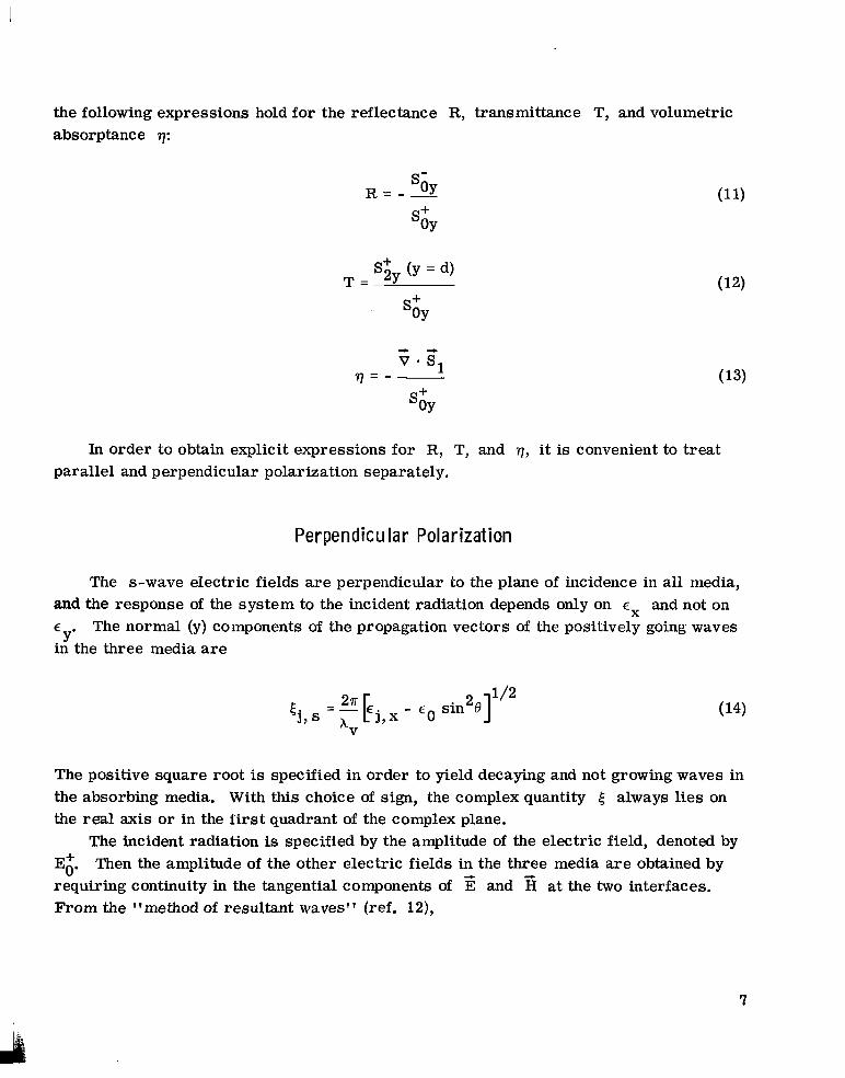
the following expressions hold for the reflectance R, transmittance T, and volumetric absorptance 17:
In order to obtain explicit expressions for R, T, and 7, it is convenient to treat parallel and perpendicular polarization separately.
Perpendicu lar Polarization
The s-wave electric fields are perpendicular io the plane of incidence in all media, and the response of the system to the incident radiation depends only on E-- and not on E
in the three media are The normal (y) components of the propagation vectors of Y'
A
the positively going waves
The positive square root is specified in order to yield decaying and not growing waves in the absorbing media. With this choice of sign, the complex quantity 5 always lies on the real axis or in the iirst quadrant of the complex plane.
E:. requiring continuity in the tangential components of E and From the "method of resultant waves" (ref. 12),
The incident radiation is specified by the amplitude of the electric field, denoted by Then the amplitude of the other electric fields in the three media are obtained by
at the two interfaces.
7
I

E l =
E; =
Ed =
+ tl, s E, V 2id5 1, s
+ rl, sr2, se
id(51, s-52, s) tl, st2, se
2id5 1, 1, sr2, se l + r
E; = 0 (19)
where the s-wave amplitude reflectance r and transmittance t. coefficients a t the (j-1, j ) interface a r e defined by
j, s 3,s
Using Maxwell's equations to eliminate H in the expressions for the Poynting vec- tor yields the following expressions for Rs, Ts, qs, and Fs:
R = S 2id5 1, s
+ '1, sr2, se
8

1, s T = tl, 2 2 , se
1 7 s 2id5 S
+ r1, sr2, se
- asd -w;, JY-d)l> + 2e Re [.2' se (23)
2
40
where
The quantity as is an absorption coefficient that depends on the angle of incidence that is discussed subsequently in more detail. .
Para1 le1 Polarization
The electric fields of the plane waves lie in the plane of incidence and have compo- nents in both the x- and y-directions. The response of media 2 and 3 to electric fields
9
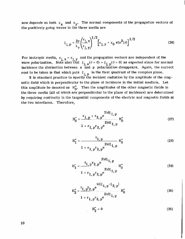
now depends on both and E The normal components of the propagation vectors of the positively going waves in the three media a r e
Y'
For isotropic media, E = E and the propagation vectors a r e independent of the wave polarization. Note also that 5 (8 = 0) = 5 . (8 = 0) as expected since for normal incidence the distinction between s and p polarization disappears. Again, the correct root to be taken is that which puts 5
It is standard practice to specify the incident radiation by the amplitude of the mag- netic field which is perpendicular to the plane of incidence in the initial medium. Let this amplitude be denoted as H;f. Then the amplitudes of the other magnetic fields in the three media (all of which are perpendicular to the plane of incidence) are determined by requiring continuity in the tangential components of the electric and magnetic fields at the two interfaces. Therefore,
j 7 x j , y j, s J, P
j, P in the first quadrant of the complex plane.
H i =
2id51 5 , p + r2,pe
1, pr2, Pe 2 id5
1, P l + r
t % K;' 1, P
2 id5 1 7 P
1, pr2, Pe l + r
H; =
2id5 1 7 P
% tl, pr2, pe 2 id5
1, P 1, pr2, Pe l + r
5, pt2,
1, l + r
H i = 0
10
where the p wave amplitude reflectance r and transmittance t coefficients at the (j-1, j) interface are given by
j7 P j, P
j = 1 , 2 (32) 5, P - - € 5 j , x j-1, p - 'j-1, x 5 j , p - r =
5 j, x j-1, p + 'j-17 x j, p j ,p E
4 Using Maxwell's equations to find E in terms of H yields the following expres- sions for Rp, Tp7 qp, and F -
P' I
R = P
T = P
2 id5 1 7 P
'1, p + r2, pe
1, pr2, Pe l + r
2id5 1 7 P
id5 1, p tL P tSP"
1, P 2id5
1 7 pr2, Pe l + r
2
(33)
(34)
11
where
between these two waves. The te rm
ap = 25;:,
takes into account all further 2idt
1 + rlr2e
(37)
is the p wave absorption coefficient.
ever, the incident radiation is often unpolarized. As discussed by Bell (ref. 9), the Poynting vector for unpolarized radiation in a solid cannot, in general, be resolved into a simple sum of s and p wave components. For inhomogeneous waves in absorbing media the Poynting vector has cross terms between the s and p polarized fields that I
result in energy flow parallel to the plane of the film. Such cross terms, however, do not contribute to the divergence of the Poynting vector since they depend only on y and not on x and z. The proper absorption per unit volume can thus be obtained for inci- dent radiation of arbitrary polarization by the usual weighted sum q = asqs + a q and a + a = 1, where as and a are the relative amounts of s and p polarized radia- tion.
The theory has, thus far, been developed for linearly polarized radiation. How-
P P S P P
Discussion of Formulas
Equations (23) and (35) are rigorous expressions for the absorption per unit volume of energy from the electromagnetic field in a thin film. The expressions are somewhat complicated but readily lend themselves to physical interpretation.
radiant energy that is refracted across the (0-1) interface into medium 1. The absorp- tion of this energy is proportional to the absorption coefficient a! and to the intensity of the radiation field, the relative magnitude of which is determined by the remaining fac- tors. The terms in braces refer successively to the relative intensity of the wave re- fracted into medium 1, the wave reflected from the (1-2) interface, and the interference
For example, the coefficient containing 1 - 1 rl I is the fraction of the incident
reflections. Thus, although full account was taken of the inhomogeneity of the electro- magnetic waves and of the anisotropy of media 1 and 2, the rigorous expressions for q are, in fact, what would be expected from an intuitive treatment of the problem.
The major modification introduced by allowing optical anisotropy is the appearance of different forms for the propagation vectors of s and p waves in media 1 and 2. Aside from this difference, the expressions obtained for the simple, uniaxially aniso- tropic media considered herein are formally identical with those for isotropic media.
The attenuation of the wave in the film is determined by the product of a! (O) and y,
I
i
12
the perpendicular distance f rom the surface. However, one usually thinks of attenuation as being related to the distance along the direction of wave propagation. These two no- tions may be reconciled by considering the limiting case of an isotropic weakly absorb- ing material. Since the rate of absorption is determined by the imaginary part of the propagation vector (eqs. (25) and (37)), the condition for weak absorption is (see eqs. (14) and (26))
2 E ; << - sin e
> Tf this inequality is satisfied, cr(f3) sorption coefficient (ref. 13) and O1 is the angle of refraction given by Snell's Law:
cy(O)/cos 01, where (~(0) = 47rk/xv is the usual ab-
n 0 s i n e = n l s i n O 1 ( 39)
This is the expected result: The attenuation is determined by the product of (~(0) and the distance along the direction of energy flow, the latter being given by y/cos el for weak absorbers. Although such an interpretation can also be given if the medium is strongly absorbing, the direction of energy flow no longer coincides with the classical angle of refraction given by equation (39) because of the strongly inhomogeneous nature of the refracted wave for oblique incidence. In such cases no simple expression for the direction of energy flow is available, and there seems to be no simple physical interpre- tation for the angular dependence of the absorption coefficient.
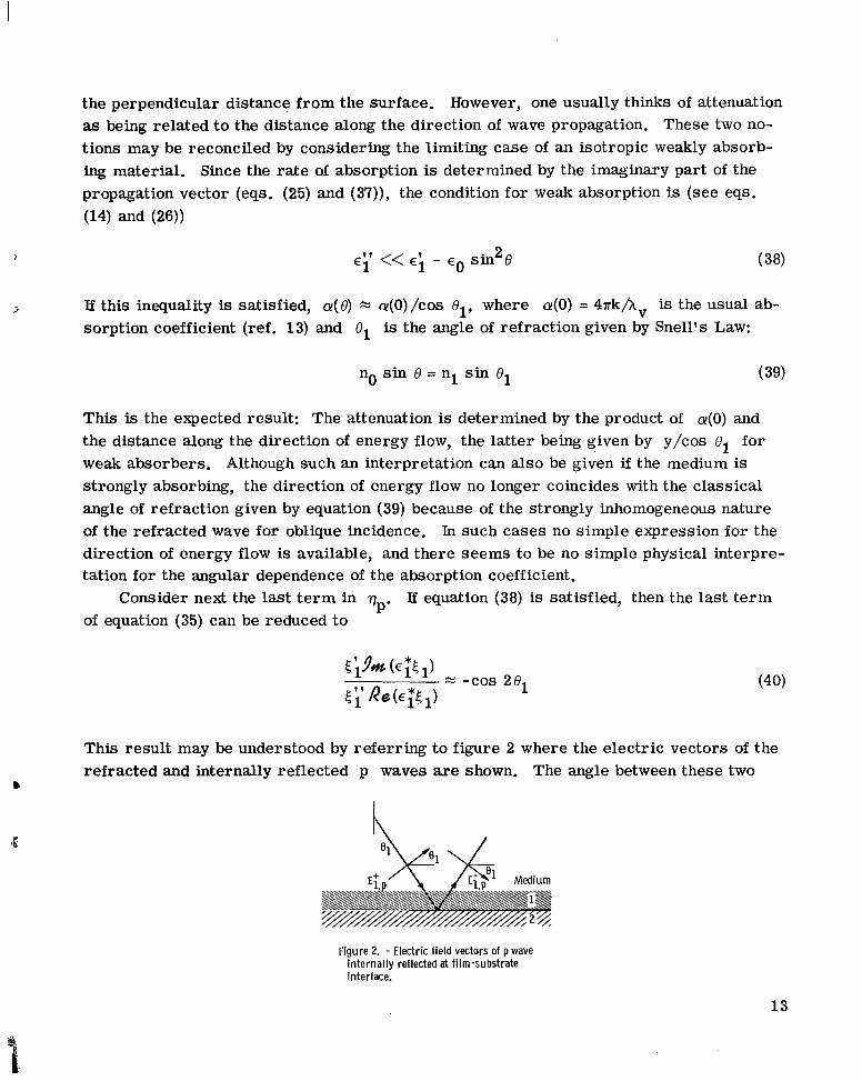
of equation (35) can be reduced to Consider next the last te rm in 7 Tf equation (38) is satisfied, then the last te rm
P'
This result may be understood by referring to figure 2 where the electric vectors of the refracted and internally reflected p waves are shown. The angle between these two
I.
Figure 2. - Electric field vectors of p wave internally reflected at film-substrate interface.
13
vectors is simply 201, so that the amplitude of the p-wave interference term is modu- lated by the scalar product of the electric field vectors of the two waves. Only the com- ponents of the electric fields parallel to each other interfere. Since the s-wave electric fields are always parallel to each other, such a scalar product does not appear in the interference te rm of q,.
Two limiting cases of F are also of interest. The limit L - 00 corresponds to all excited electrons having an equal chance of being emitted, regardless of the point of ex- citation in the photoemitting medium. In this case the quantum yield Y is just propor- tional to the number of photons absorbed by the photoemitter. In fact, if the absorptance of the film is denoted by A, it can be shown that
lim F(L) = A L-00
Thus in addition to the standard expression for the absorptance A of the film, A = 1 - R - T, an equivalent expression is available in which the contributions of the re- fracted, internally reflected and interference terms have been explicitly separated out.
limit, The limit d -c 00 corresponds to emission from a semi-infinite medium. In this
F(L) = I I a+- L
where the polarization subscripts have been omitted. An identical expression has been obtained by Spicer (refs. 4 and 5) for normal incidence on an isotropic medium. This widely used expression is also valid for oblique incidence and materials with the simple form of anisotropy considered herein provided that the expression for the reflectance rl (eqs. (20) and (32)) and absorption coefficient CY (eqs. (25) and (37)) are used.
There is an important generalization of the preceding formulation if medium 2 is replaced by a multilayer structure. Following the method of Rouard as outlined by Heavens (ref. 14) makes it necessary only to replace r2s and r in the expressions for R, q, and F by the amplitude reflectance coefficient for the composite medium 2. For example, if medium 2 is decomposed into a film of thickness d' (medium 2) and a substrate (medium 3), then
2P
2id'5
2id'5
r + r e 2 3
1 + r2r3e r2 - (4 3)
14

where equations (20) and (32) hold for the amplitude reflectance coefficients at the (1-2) and (2-3) interfaces. This method is useful for dealing with spaced-reflective photo- cathodes (ref. 15) and may be employed for calculating the total optical properties of any multilayer system.
I LLU STRATI ON 4
The responses of metals to vacuum ultraviolet radiation are currently being studied
electrons in the solids. The optical studies are frequently performed on thin films since the purest and most specular metal specimens are fabricated by vapor deposition of films in the submicrometer thickness range. This section illustrates the utility of the preceding analysis by considering, in some detail, the optical physics of the angular de- pendence of photoemission from a thin metal film.
many metals and therefore will be used for the illustrative example. X v < 837 with an index of refraction less than 1. Therefore, it is also well suited for illustrating the approximations for weak absorbers discussed previously.
Consider a 1000-&thick isotropic aluminum film on a glass substrate. The alumi- num surface is assumed to be illuminated by radiation of wavelength hv = 584 A at an angle of incidence 8 and the emitted electrons are collected in a vacuum. This partic- ular wavelength was chosen because the optical constants of aluminum and glass are well known for this very strong line of the helium spectrum. The optical constants of alumi- num and glass are cl = (0.71 + 0.018 i)2 and c2 = (0.83 + 0.45 i) , respectively (ref. 18). The thickness of the film (1000 A) is comparable to the wavelength of the inci- dent radiation, and thus interference effects are expected to appear.
For 8 < 45' the inequality of equation (38) is satisfied, so that the behavior of the waves in the film may be described in the familiar terms of waves in a dielectric film. The absorption of radiation q within the film is plotted in figure 3 for 8 = 30' and 60'. For the s-wave incident at 8 = 30°, the usual exponential attenuation of the absorption is modified by the standing wave produced by interference between the refracted wave and the wave reflected from the aluminum-glass interface. The wavelength of the stand- ing wave is obtained from the argument of the exponential in the interference term of qs as "/e;, = 600 A.
tion is refracted into the aluminum at an angle O1 x 45'. The electric fields of the two waves in the film are at right angles and do not interfere. Mathematically this suppres-
3 to determine both the band structure (ref. 16) and collective behavior (ref. 17) of the
Aluminum exhibits optical properties in this wavelength region that are typical of In addition, for
its "plasma wavelength, T f aluminum acts as a weakly absorbing dielectric
2
b '
B
A standing wave is not produced by the p-wave incident at 30°, because the radia-
15

sion of interference is expressed by the vanishing of the coefficient of the p-wave inter- ference te rm (eq. (40)), since cos 2e1 = 0 for
classical experiments on standing waves in air in front of a highly reflecting surface (refs. 19 and 20). The preceding discussion extends the elementary analysis to the standing waves in an absorbing thin film.
The phenomenon of total reflection exhibited by transparent media is also exhibited (ref. 21), in modified form, by aluminum for wavelengths below the plasma wavelength. Since the index of refraction is less than 1, a critical angle for total reflection exists for incidence from the vacuum. For 8 > BC, where 8, vacuum-aluminum interface approaches 1, and the wave in the film no longer propagates with weak attenuation but instead is strongly attenuated (evanescent). The absorption length is given approximately by
= 45'. Standing waves are usually presented in textbooks on optics in terms of Wiener's
c
sin" nl, the reflectance of the <
a + ? ) = I (44)
It may be verified that the inequality of equation (38) is not satisfied for 8 > BC, since the attenuation of the refracted wave is so strong.
For 8 = 60°, am' = 95 A and the usual exponential decrease for qs is depicted in figure 3. The behavior of q is similar. In the example chosen here the evanescent P
1.1~10-3 r
L I 1 1 - 1 1 1 1 1 1 1 1 1 1 1 1 0 50 100 150 200 250 NO 350 400 450 500 550 600 650 700 750 800 850 900 950 loo0
Distance from irradiated surface, y, A Figure 3. - Absorption per unit volume through a 1000-A-thick a luminum f i lm on a glass substrate.
Incident wavelength, 584 A.
16

wave in effect never reaches the substrate, there is no wave reflected at the aluminum- glass interface, and the absorption is well described by exp ( -ay) . However, for film thicknesses of the order of 100 & the evanescent refracted wave does generate a re- flected wave (also evanescent) at the aluminum-glass interface that interferes with the refracted wave, and the full expression for 77 should be used. The interference of these waves, however, would not result in absorption periodic in the y-coordinate (as in qs (30°)), since their dependence on y is that of a decaying exponential.
In order to evaluate the relative gain in photoemission for oblique incidence G(B), a numerical value of L, the electron attenuation length, must be chosen. There are in- dications (ref. 22) that the attenuation length of electrons excited by light below the plasma wavelength of metals may be less than 50 & The relative gain for both p and s polarization is thus plotted in figure 4 for L = 5, 15, 25, and 35.
>
2 . 8 r Electron
attenuation length,
(a) Perpendicular (sl polarization.
4.5r n
pi 4.0 V
U c .- 3.0
2 2.5 0 c
.- % 2.0- c W -
1.5- I c t L 1.0-.- a 2 . 5 - L
0 Angle of incidence, 8, deg
(b) Parallel (p) polarization.
Figure 4. - Angular dependence of photoemission from 1WO-A-thick aluminum film on glass substrate. Wavelength of incident light, 584 A.
17

Since most of the photoelectrons originate close to the surface, the yield is deter- mined by the magnitude of the electric field in this region. The relative maximums and minimums exhibited by Gs( 8) for 8 < Qc are respectively due to the appearance, near the surface, of antinodes and nodes of the electric field of the standing wave (and hence of the absorption through eq. (10)) in the interior of the film. The interference of p- waves within the film is suppressed for oblique incidence, so that oscillations are not exhibited by G ( e ) to the extent that they are by Gs(8).
to angles away from the normal (since nl < no). Radiant energy is deposited closer to the surface and the excited electrons suffer less attenuation. tance at the vacuum-aluminum interface approaches 1, little radiation is refracted into the film and the emission drops to 0.
the electron attenuation length for 6 L OC. Thus, an experimental measurement of pho- tocurrent as a function of angle of incidence and its comparison with the theoretical curves of figure 4 suggest a new method of determining the attenuation length of excited electrons.
(2) the photoyield as a function of film thickness, or both (ref. 23). However, for X v < 1050 stants of very thin films a r e a function of film thickness. The relative gain method may employ an opaque substrate and has the advantage that optical and photoelectric proper- ties may be determined for a single film, without the necessity of using some average value of e l for films of different thickness.
very thick films the characteristic oscillations produced by interfering waves a r e absent. However, the increase of the yield to a maximum near 0 films and is simply due to the fact that radiation is refracted away from the normal s o that the electrons are excited closer to the surface. The existence of this maximum has been noted by many investigators and has been exploited to improve the response of metal photoelectric detectors to vacuum ultraviolet radiation of wavelength less than the plasma wavelength of the metal (ref. 24).
P The general increase in yield as 0 approaches BC is due to refraction of radiation
For 8 > Oc the reflec- 5
As shown in figure 4, the relative gain curves are rather sensitive to the value of
Present methods of determining L require either (1) transparent substrates, or
no transparent substrates exist and it is well known that the optical con-
Although the preceding discussion pertains to thin films, it should be noted that for
continues to hold for thick C
CONCLUSIONS
Equations for the quantum yield of a thin film photoemitter were formulated on the basis of classical thin film optics. The expressions are valid for all angles of incidence and arbitrary values of the dielectric functions of the initial medium, film, and sub-
18

strate. To aid in application to ordered structures such as epitaxial films and single crystals, both film and substrate were allowed uniaxial optical anisotropy with the optic axis normal to the plane of the film. The formulation is sufficiently general to be useful for wavelengths from the threshold of photoemission in the near infrared to the soft X- ray region and for both metals and semiconductors. Finally, a new method for deter- mining the value of the electron attenuation length was suggested.
Lewis Research Center, National Aeronautics and Space Administration,
Cleveland, Ohio, October 8, 1969, 124-09.
19

APPENDIX - SYMBOLS
A
C
C
d
E
F
G
H
K
k
L
n
P
R
r
'1
absorptance of film r2 amplitude reflectance coefficient of
parameter for excitation and escape 1-2 interface
probability S Poynting vector
velocity of light
film thickness
electric field
function containing optical absorption and diffusion steps in photoemis- sion process
relative gain for oblique incidence
magnetic field
propagation vector of electro- magnetic fields
s polarization perpendicular to incident plane f
T transmittance of film
tl amplitude transmittance coefficient
t2 amplitude transmittance coefficient
Y quantum yield of film
y distance from irradiated surface
a! absorption coefficient
of 0-1 interface
of 1-2 interface
extinction coefficient E dielectric function
attenuation length of excited electron
index of refraction q absorption per unit volume
polarization parallel to incident B angle of incidence
permitivity of vacuum
permeability of vacuum plane PV
reflectance of film
radius vector
amplitude reflectance coefficient of
5 y component of propagation vector
$' field component
0-1 interface
20

I
REFERENCES
1. Fry, T. C.: Plane Waves of Light. J. Opt. SOC. Am., vol. 22, no. 6, June 1932, pp. 307-332.
2. Ives, Herbert E. : The Vectorial Photoelectric Effect in Thin Films of Alkali Metals. Phys. Rev., vol. 38, no. 6, Sept. 15, 1931, pp. 1209-1218.
3. Spicer, W. E. : Photoemissive, Photoconductive, and Optical Absorption Studies of Alkali-Antimony Compounds. Phys. Rev., vol. 112, no. 1, Oct. 1, 1958, pp. 114-122.
T
4. Spicer, W. E. ; and Wooten, F. : Photoemission and Photomultipliers. Proc. IEEE, vol. 51, no. 8, Aug. 1963, pp. 1119-1126.
5. Berglund, C. N. ; and Spicer, W. E. : Photoemission Studies of Copper and Silver: Theory. Phys. Rev., vol. 136A, no. 4, Nov. 16, 1964, pp. 1030-1044.
6. Berglund, C. N. ; and Spicer, W. E. : Photoemission Studies of Copper and Silver: Experiment. Phys. Rev., vol. 136A, no. 4, Nov. 16, 1964, pp. 1044-1064.
7. Hansen, Wilford N. : Electric Fields Produced by the Propagation of Plane Coherent Electromagnetic Radiation in a Stratified Medium. J. Opt. SOC. Am., vol. 58, no. 3, Mar. 1968, pp. 380-390.
8. Stern, Frank: Elementary Theory of the Optical Properties of Solids. Solid State Physics. Vol. 15. Frederick Seitz and David Turnbull, eds., Academic Press, 1963, pp. 299-408.
9. Bell, E. E. : Optical Constants and their Measurement. Light and Matter. Vol. 25, Pt. 2a of Handbuch der Physik. S. FlGgge, ed., Springer-Verlag, 1967, pp. 1-58.
10. Mosteller, L. P., Jr.; and Wooten, F. : Optical Properties and Reflectance of Uniaxial Absorbing Crystals. J. Opt. SOC. Am., vol. 58, no. 4, Apr. 1968, pp. 511-518.
11. Melnyk, Andrew R.; and Harrison, Michael J.: Resonant Excitation of Plasmons in Thin Films by Electromagnetic Waves. Phys. Rev. Letters, vol. 21, no. 2, 4
July 8, 1968, pp. 85-88.
1. 12. Heavens, 0. S. : Optical Properties of Thin Solid Films. Dover Publ., Inc., 1965, p. 59.
1964, p. 614.
p. 63.
13. Born, Max; and Wolf, Emil: Principles of Optics. Second ed., Pergamon Press,
14. Heavens, 0. F.: Optical Properties of Thin Solid Films. Dover Publ., Inc., 1965,
21
15. Novice, M. A.; and Vine, J.: Optical Means for Enhancing the Sensitivity of a Tri-
16. Abelss, F., ed.: Optical Properties and Electronic Structure of Metals and Alloys.
Alkali Photocathode. Appl. Opt., vol. 6, no. 7, July 1967, pp. 1171-1178.
Interscience Publ., 1966.
17. Steinmann, W. : Optical Plasma Resonances in Solids. Phys. Stat. Solidi, vol. 28, no. 2, Aug. 1, 1968, pp. 437-462.
r 18. Madden, R. P.; Canfield, L. R.; and Hass, G.: On the Vacuum-Ultraviolet Re-
flectance of Evaporated Aluminum Before and During Oxidation. J. Opt. SOC. Am., vol. 53, no. 5, May 1963, pp. 620-625. t
19. Born, Max; and Wolf, Emil: Principles of Optics. Second ed., Pergamon Press, 1964, p. 277.
20. Jenkins, Frances A. ; and White, Harvey E. : Fundamentals of Optics. Third ed., McGraw-Hill Book Co., Inc., 1957, p. 527.
21. Hunter, W. R. : Optical Constants of Metals in the Extreme Ultraviolet. I. A Mod- ified Critical-Angle Technique for Measuring the Index of Refraction of Metals in the Extreme Ultraviolet. J. Opt. SOC. Am., vol. 54, no. 1, Jan. 1964, pp. 15-19.
22. Quinn, John J.: Range of Excited Electrons in Metals. Phys. Rev., vol. 126, no. 4, May 15, 1962, pp. 1453-1457.
23. Crowell, C. R.; and Sze, S. M. : Hot-Electron Transport and Electron Tunneling in Thin Film Structures. Physics of Thin Films. Vol. 4. Georg Hass and R. E. Thun, eds., Academic Press, 1967, pp. 326-371.
24. Samson, James A. R. : Techniques of Vacuum Ultraviolet Spectroscopy. John Wiley & Sons, Inc., 1967, p. 238.
22
NATIONAL AERONAUTICS AND SPACE ADMINISTRATION WASHINGTON, D. C. 20546
OFFICIAL BUSINESS FIRST CLASS MAIL
POSTAGE AND FEES PAID NATIONAL AERONAUTICS AND
SPACE ADMINISTRATION
'The aeromirticnl aizd space cictitlities of the United Stntes shnll be couducted so as to contsibzrte . . . t o the expmzsioa of hiriiiaiz kizoiol- edge of pheizoiuem iu the ntntosphere nad space. The Admiizistsation sb~ill prot'ide fos the widest psacfiwble and appiopsiate dissemiizariou of iiifor-i~ta~ioiz concerizing its nctiilities a i d the i e s ~ l t s theseof."
-NATIONAL AERONAUTICS AND SPACE ACT OF 1958
NASA SCIENTIFIC A N D TECHNICAL PUBLICATIONS
TECHNICAL REPORTS: Scientific and technical information considered important, complete, and a lasting contribution to existing knowledge.
TECHNICAL NOTES: Information less broad in scope but nevertheless of importance as a contribution to existing knowledge.
TECHNICAL MEMORANDUMS: Information receiving limited distribution because of preliminary data, security classifica- tion, or other reasons.
CONTRACTOR REPORTS: Scientific and technical information generated under a NASA contract or grant and considered an important contribution to existing knowledge.
TECHNICAL TRANSLATIONS: Information pitblished in a foreign language considered to merit NASA distribution in English.
SPECIAL PUBLICATIONS: Information derived from or of value to NASA activities. Publications include conference proceedings, monographs, data compilations, handbooks, sourcebooks, and special bibliographies.
TECHNOLOGY UTILIZATION PUBLICATIONS: Information on technology used by NASA that may be of particular interest in commercial and other non-aerospace app!icationc. Publications include Tech Briefs, Technology Utilization Reports and Notes, and Technology Surveys.
Details on the availability of fhese publications may be obtained from:
SCIENTIFIC AND TECHNICAL INFORMATION DIVISION
NATIONAL AERONAUTICS AND SPACE ADMINISTRATION Washington, D.C. 20546