the networked video jukebox
TRANSCRIPT
IEEE TRANSACTIONS ON CIRCUITS AND SYSTEMS FOR VIDE:O TECHNOLOGY, VOL. 4, NO. 2. APRIL 1994 IO5
The Networked Video Jukebox Laurence Crutcher, Member, IEEE, and John Grinham
Abstract-The availability of low-cost compressionddecompres- sion (codec) hardware for video and audio has given us the opportunity to provide multi-media applications over data net- works. This paper describes a particular system tlhat we have built to demonstrate this capability. A video jukebox has been built using off-the-shelf computers connected over Ethernet. For wide area connectivity, SMDS attachment has been used. Combined video and audio clips can be selectively played on a PC equipped with low cost video and audio codec cards, using JPEG and ADPCM compression hardware. The data for these clips is retrieved in real time from a Unix workstation via the network. Following a description of the system design, the ]performance obtainable from a number of network configurations is shown from the results of the experiments we have conducted. These results show that the addition of real-time transport software on top of the standard Internet protocols allows us to provide video and audio clips with a system comprising standard off-the-shelf equipment. The quality of these clips is considered acceptable for many applications. We have quantified the capacity of the system in terms of the data rates and the number of users, and have identified which parts of the total system become bottlenecks as each of these parameters is increased. Solutions to overcoming these bottlenecks are described.
I. INTRODUCTION
HE availability of low-cost compression/decompression T (codec) hardware for video and audio has given us the capability to provide multi-media applications over data net- works. Data networks that can support the reduced bandwidth of compressed video and audio are in place and readily available. Powerful desk-top computers that can process this data are rapidly advancing to the point where they are com- modity items. Together, these technologies presenc. an exciting opportunity to provide applications that utilize video and audio to users now.
The acceptance of new applications employing multi-media is dependent on a balance between price and performance. It is therefore appropriate to ask just what is achievable with the technology that is available, and to attempt to identify limitations in systems built with this technology. Further, we should quantify how the capabilities of a system increase as we make advances in each of the limiting areas.
This paper adopts this approach, using the design and performance of a networked video jukebox that we have built as the basis of our study. The video jukebox allows a user to view video clips, with stereo audio, on a PC equipped with low cost video and audio codec cards, using JPEG and
Manuscript received July I . 1992; revised August 23, 1992. L. Crutcher is with the Market Vision Corp., 40 Rector Street, New York,
J. Grinham is with Hewlett Packard Laboratories, Bristol BSI2 642,
This manuscript was recommended by Ali Tabatabai. IEEE Log Number 9215864.
NY 10006. This work was carried out as an employee of Hevilett Packard.
England.
ADPCM compression hardware. The jukebox is operated from a Windows application that presents the user with a control panel of the type used for remote control of a domestic video recorder. The user can view a list of the clips available and control the display of a clip through the selection of the appropriate buttons on this panel. All of the data for the clips is stored on the hard disk of a remote server with which the client communicates over an intervening network. The server is a Unix workstation. Applications for this specific type of system include training, education and video mail.
The prototype system uses Ethernet to connect the client and server over the local area. Experiments have also been conducted with the client and servcr on separate LANs inter- connected via a T1 SMDS link [ I ] . The operation of the video jukebox over networks with modest bandwidth is enabled by the use of compressed video and audio. The PC contains two cards that provide compression and decompression of video and audio in real time. Thus the PC is used to record clips, which are then transferred to the server for storage. As the jukebox client, the same PC decompres5es the clip during play back.
The motivation for the work reported here is to examine the requirements and possible solutions for networked multi-media applications from a systems perspective. The video jukebox is an example of a specific class of application that focuses this study. Previous articles in the literature have looked at similar systems from either a qualitative [2] or theoretical 131 point of view. This paper complements that work with a study based on measurements from a working system.
The components of the system can be categorized into the following areas.
Computers for the client and server. Video and audio subsystems. Network connecting client and server. Network services. Application software.
In building and testing the video jukebox, our aim is to isolate the particular problems presented by each of these components, and to identify possible solutions. The main ob- jective is to use off-the-shelf equipment wherever possible, and to demonstrate where the limitations are with this approach. We have quantified the capacity of the system in terms of the data rates and the number of users, and have identified which parts of the total system become bottlenecks as each of these parameters is increased. Solutions to overcoming these bottlenecks are described.
We have shown that a working system can be built using off-the-shelf parts, together with some software for end-to-end protocols. This system provides video and audio with a quality
1051-8215/94$04.00 0 1994 IEEE

106 IEEE TRANSACTIONS ON CIRCUITS AND SYSTEMS FOR VIDEO TECHNOLOGY, VOL. 4. NO. 2, APRIL 1994
considered acceptable for many applications. Specifically, we have made the following measurements.
A standard 386 PC client, equipped with video and audio hardware, connected to a standard HP series 400 Unix workstation configured as a video and audio file server, is sufficient to support a compressed video stream of 256 x 160 pixels at 20 framedsec in full color alongside a stereo audio channel of 4 bit ADPCM. The bit rate of such a stream is - 0.8 MBit/s. Up to 8 such streams could be supported on a single 802.3 network dedicated to this application, without noticeable degradation of the image or audio quality, and in addition a single stream can be supported over an SMDS WAN using the current prototype HP 802.3-SMDS router. The number of clients that can be served simultaneously by a server is dependent on disk performance and the distribution of data blocks over the disk. In the worst case, without imposing any constraints on this distribution or on the scheduling policy in the file system, the HP 400 workstation used in our experiment could support about 8 clients, each reading a separate video and audio clip. At the time of writing, the latest disk technology could be expected to double this number.
Our general observations on how to extend networked mul- timedia systems to handle higher data rates, more clients, and other classes of applications, are described in the concluding section of this paper.
In the next section of this paper, an overview of the system architecture is given which covers the configuration of the components and the video and audio subsystem. The following section then gives an analysis of the performance of the system components and defines the limits within which the system will operate. Vie network services and software design are described in Section IV. Section V shows the results of the measurements that have been made on the system in different configurations and Section VI discusses the implications of these results. The paper is concluded in the last section.
11. SYSTEM ARCHITECTURE
I . Hardware Cunjiguration
The hardware consists of a client HP Vectra RS25/C PC equipped with prototype video and audio decompression hard- ware' , connected via standard network interfaces to an HP 9000/400 series workstation server (Fig. 1).
The most simple network configuration for connecting the client and the server used a private Ethernet LAN. The only other station on this LAN was a network monitoring tool which allowed detailed network traffic measurements to be made. Further experiments were conducted with the system in the presence of other LAN traffic and also with a connection over an SMDS wide area network. This last configuration is shown in Fig. 2.
1 .A. video Subsystem The Videologic prototype video codec was built around
a C3 Microsystems JPEG compressioddecompression chip
' Manufactured by Videologic Limited.
q-1 Network Interface
Standard HF 9000/400
Workstation
Network Interlace
Audio File Storage
Fig. I . Video Jukebox Hardware Configuration.
PC Cllent HP 80'2 3 lo SMDS Rouler
W
Fig. 2. Wide Area Network Configuration.
controlled by an on card transputer together with a 256 KByte FIFO for incoming and outgoing data storage. The transputer controls the interface to the host PC, the setting up of the compression chip, and the management of the FIFO. The prototype transputer code allows the user to select the image size to be coded together with the frame rate and quantization levels.
The JPEG standard is aimed at continuous tone still image compression so there is no inter-frame compression. The addition of inter-frame compression such as in the MPEG standard would increase the compression by a factor of about 3. While MPEG is targeted at 1.5 Mb/s, there is no inherent reason that the standard could not be used at the lower bit rates used in these experiments to obtain higher quality images and audio. (For a detailed description of JPEG and MPEG, see the articles in [4].)
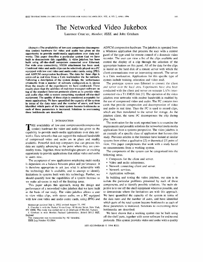
Fig. 3 shows the JPEG-coded frame sizes against time for the trailer sequence of the film 'Buster' which was used in the experimental sections of this work. The scene changes in this sequence can be clearly seen. Typical variations with JPEG on this type of material are of the order 3: 1, considerably smaller than the 10: 1 variations which could be expected using MPEG. It is important to note that different image sequences would
CRUTCHER AND GRINHAM: THE NETWORKED VIDEO JUKEBOX 107
Frame Sues of JPEG encoded film dip. __-
rl
__- w
0 0 20 Jo .o Tl" (.,
Fig. 3. JPEG Compressed Frame Sizes.
have quite different characteristics. A sequence that consisted of a long 'talking-head' shot followed by a steady text frame would effectively be at two distinct data rates.
l .B. Audio Subsystem The audio codec is a general purpose DSP chip which is
programmed to implement two channels of 4 bit ADPCM compression on 16 bit input samples at sampling rates of either 9.45 kHz, 18.9 kHz or 37.8 kHz. This card also has a controlling transputer and a 64 Kbyte FIFO which corresponds to around 6 seconds of audio at a sample rate of 9.45 kHz and 8 bits per stereo sample.
In our experiments we used stereo 4 bit ADPCM at the lowest sample rate and played the audio back through small single speakers. While this is a highly subjective result, we judged the quality to be similar to high quality AM radio, and quite effective in stereo for replaying a film soundtrack.
1 .C. Video and Audio Synchronization VideoLogic's prototype video and audio system was orig-
inally designed to store and replay video and audio from a local disk. The modifications necessary to run the system using a remote filestore were carried out at Hewlett-Packard Labs by the authors. In Videologics original protorype stand- alone system there is no explicit synchronization recovery mechanism. The compressed audio and video data are stored in separate files. A third file is created during recording and used for two functions. The first is to index on a frame by frame basis into the video data file. This is required because of the variable compressed frame length. The second function is to retain a list of frame display times associated with each frame. This is required if, due to host system overheads, it is not possible to continuously transfer data to the local disc at the required rate so that recorded frames are no longer compressed at the nominal rate.
To play back a clip in the stand-alone system, I he decom- pression subsystem first opens the locally stored files, gets the audio and video parameters, and then displays the first video frame in the clip. It then requests a block of audio data samples, queues them in its local FIFO and starts playing them back. Requests are then issued for video fram1:s from the
- Fig. 4. Video Jukebox Software Architecture.
local file system. These are obtained together with the display time from the index file. The frame and its display time are transferred, queued in the local FIFO, and then displayed for the required amount of time.
This scheme inherently makes the assumption that no frames are lost between recording and playback. If they are then synchronization between the audio and video channel is lost. The implications of this in a networked environment are discussed in Section VI.
l.D. Video Overlay and Capture The video overlay card is connected to the compression card
via a digital bus that is closely related to the CCIR 601 digital video standard. Using this bus decompressed video from the compression card can be chromakeyed into a display window or alternatively analog video can be frame grabbed, digitized, and fed to the compression card.
When in capture mode the image size can be scaled before grabbing to a variety of sizes from 192 x 128 pixels to 352 x 256. We mostly used 256 x 160 which occupies roughly a quarter of a VGA screen. During playback it is possible using this card to expand the picture so that the original 256 x 160 image can be blown up to 484 x 320 pixels, which is roughly 50% of the graphics area. With the very small viewing distances that are used with computer displays this picture zooming is not particularly useful-the image defects are highlighted and are very noticeable. However, at viewing distances more closely associated with television the picture looks similar in quality to VHS video.
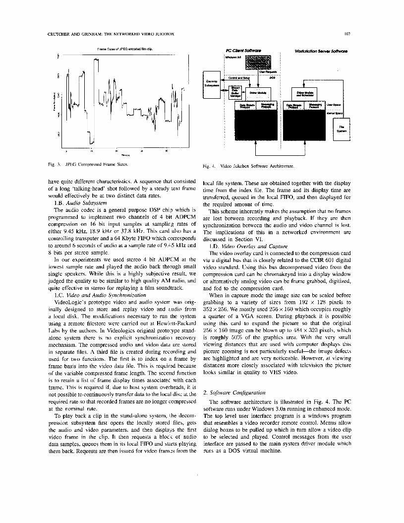
2. Software Configuration
The software architecture is illustrated in Fig. 4. The PC software runs under Windows 3.0a running in enhanced mode. The top level user interface program is a windows program that resembles a video recorder remote control. Menus allow dialog boxes to be pulled up which in turn allow a video clip to be selected and played. Control messages from the user interface are passed to the main system driver module which runs as a DOS virtual machine.

108 IEEE TRANSACTIONS ON CIRCUITS AND SYSTEMS FOR VIDEO TECHNOLOGY, VOL. 4, NO. 2, APRIL 1994
This software architecture takes advantage of the ability of Windows 3.0a to multitask between the Windows programs and any number of DOS virtual machines that are running. The driver module, which contains all the protocol processing and is also responsible for the data transfer of the video and audio streams from the network to the decompression hardware, can thus be allocated a large number of time-slices compared to the windows program. The effect of other system activity such as movement of windows or the mouse can therefore be minimized. This is discussed in more detail in Section 111.
The driver module takes messages from the user interface program and calls the top-level protocol functions as described in Section 111. Under normal circumstances the control protocol will complete correctly and the driver module will be able to read audio and video data from the top level of the data stream protocol. The control and data protocols are built directly on top of HP's DOS Arpa sockets product. This provides Berkeley sockets network services on a PC.
Transfer of the video and audio data to the decompression subsystem from the network subsystem is done using a shared buffer area and a special token. The driver module requests a token from the decompression subsystem, requests buffer space from the buffer manager and then, if the decompressor has room for the data in its receive FIFO, it looks at the top of the data stream layer to see which type of data is waiting to be received. 'The data, which in the case of video must be a whole frame, is copied into the shared buffer and the token is handed back to the decompression subsystem with information on the type and amount of data in the shared buffer. This data is then asynchronously read, queued, decoded, and displayed by the decompression subsystem.
The server software operates in user space and, similarly to the PC, the underlying communications software is HP's Berkeley sockets implementation. The video and audio files are stored on the workstations internal disk as part of its normal file system. Storage on to a raw disk partition has not been used in this implementation.
111. ANALYSIS
1. Overview
The basic premise of the networked video server is that the isochronous video and audio data can be read from a remote disk and transferred to the client over an existing computer data network at a controlled rate. The important factors in determining the perceived audio and video quality are the mean data rate and the data loss rate. Data loss in this context effectively includes data that arrives too late or out of order.
Data loss can be caused both by bit errors on the network and by overflowing or emptying of data buffers. Data loss on the audio channel results in very noticeable clicks and pops. Fortunately, even though the coding is essentially differential on a sample by sample basis, the data is packetised into self contained chunks which can be played without reference to previous data. 'Thus loss of a packet does not cause all the following data to be unplayable.
Data loss on the video channel is not so instantly noticeable. At 20-25 frames/second it is quite possible to lose a frame without the viewer noticing. However, since there is no explicit time synchronization between the two channels, data loss gradually degrades the lip synchronization. Lip synchroniza- tion effects become noticeable when the timing of the sound relative to the video exceeds approximately -40 ms to +20 ms [ 5 ] , but its importance is highly dependent on the material being viewed and the susceptibility of the viewer.
The mean rate and delay variance at the receiver must therefore be controlled sufficiently accurately to ensure that the probability of the FIFOs on the compression cards overflowing or emptying is sufficiently low. On the system we used, if the audio FIFO empties then both the audio and video replay stops until more audio data arrives. If the FIFOs become full the compression subsystem no longer requests data from the host machine. Since there is no packet by packet feedback to the server, more data arrives on the network and has to be queued in the network subsystem. The queue lengths available in the network subsystem are quite small (around 10-20 KBytes) and so data is soon discarded resulting in a very high data loss.
The variance of the data arrival at the compression subsys- tem is set by a combination of five processes:
Server data read function. Server data transfer function to its network subsystem. Network access delay. Client network read function. Client data transfer function to the decompression sub-
The significance of each of these processes is assessed in system.
the following sections.
2. Server Data Read Function
On the server the system clock can be used to control the read and data transfer processes to try and maintain an isochronous data transfer to the network subsystem. The pro- cesses were run in user space on a standard Unix workstation so the accuracy with which this can be done depends on the clock itself and on any other operating system activity.
The mechanism used to read the system clock on the server gave a clock resolution of 0.1 milliseconds. This effectively sets the lowest limit on the isochronicity of the server read and transfer process.
The operating system activities can be divided into two components. Those directly related to the user process, specif- ically data caching and read time on the file system, and those entirely independent of the user process.
Data caching by the kemel causes data to be read from the file system in file system block size units and stored in memory. As a result file system reads at contiguous locations within a file will take a variable amount of time depending on whether all the data is in the cache already and how much extra data is being read. The caching algorithm employed on HP-UX 8.0 is quite simple: when the last fragment in a block is read as part of a sequential read, the next block of the file is also read into the buffer cache. So the last read on a cached block incurs the overhead of reading the next complete block.
CRUTCHER AND GRINHAM: THE NETWORKED VIDEO JUKEBOX 109
The read time on the file system is dependent primarily on the disk performance. Disk seek times at around 16-17 ms plus 8 ms of rotational latency for 5.25’’ disks are available on Hewlett-Packard’s current workstations and some improve- ments can be expected with smaller disks. The seek, settling, and rotational delays significantly reduce the disk performance if multiple streams are read randomly off the same disk. In the worst case if the block size is 8 Kbytes and successive blocks are distributed across the disk then the throughput of a 4 MByte/s 5.25” disk falls to - 300 KByte/s, wlhich would only be enough to support a couple of 1 MBit/s isochronous streams. Increasing the block size to 32 KBytes increases the throughput to around 1 Mbyte/s, enough for 8 independent streams. A disk rated at 10 MByte/s with a total seek and rotational latency of around 12 ms, transferring random 32 KByte blocks would have a throughput of around 2 Mbyte/s, sufficient for 16 independent 1 Mbit/s streams. It should be noted that these figures are for worst case distributions of data blocks.
The application independent factors affecting the server data read process can be minimized by leaving only the basic system processes running and ensuring that there is sufficient memory available on the machine to avoid paging. As the experimental results will show, these processes are negligible when compared to the disk performance.
3. Server Datu Transfer Function
The server data transfer function is affected by the same independent operating system factors as the read psocess. The server dependent activities are as follows:
The data copy from the user buffer to a kernel buffer. The protocol processing to convert the user (data into a
The queueing time and copying time from the kernel
Variable delay can occur in the execution time of the send call if either an independent system process is scheduled or if the network card has insufficient buffers available to allow the transfer. The latter will only occur if previous packets are still queued in the card because of excessive network access delays or if the required peak data transfer rate cannot be supported by the card.
packet suitable for transfer to the network card.
buffer to the network card.
4. Network Access Delay
The local network available to us for this work w,as Ethernet (others are considered in Section IV). For experiments in the wide area we had access to a point-to-point 1.5 ME it/s SMDS link via a prototype gateway.
The video server could operate in one of three LAN environments. The first and simplest would be a private network with only one server and multiple clients receiving the same data. The second case would be with two or more servers on a private network supporting a number of clients.
particularly startling result it does serve to remind us that network protocols that allow multicast transmission, do not use acknowledgements, and do not congest the network with management activity, can enable a single server to broadcast video and audio streams to multiple clients with only the propagation delay to consider.
The behavior of the system with two servers on an Ethernet network depends to some extent on the design of the network interfaces. If the network interfaces assert an interrupt between the transmission of each packet then it is likely that the interrupt service time will be longer than the Ethernet inter- packet time. Thus two servers would quickly synchronize: one defers to the other and then transmits without contention from the first. Thus the variability of the delay experienced by each packet would effectively be restricted to the maximal length packet transmit time of around 1.2 millisecond.
The situation becomes almost impossible to predict if the server(s) have to coexist on a shared LAN. Since Ethernet does not provide any MAC layer priorities or service guarantees it is not possible to separate out the isochronous data from the ordinary computer data. If any headway is to be made in characterizing the possible performance, some assumptions have to be made on all of the following:
Distribution and number of machines on the network. Packet length distribution from each machine. Data load on each machine and the impact of higher level
Some observations can be made. In many environments the long term average LAN utilization is of the order of just a few percent. Significant increases in the utilization occur during the course of the day where the minute by minute average might peak at 5-10%. In the very short term, i.e. on a second by second basis, very high peaks corresponding to file transfers may occur. In a laboratory environment our own measurements and those shown in [6] indicate that packet distributions are bimodal with the peaks towards the shortest and at the longest packet lengths.
For the video server the most important measure of the network is the variability of the packet delay. An extensive experimental study [7] conducted measurements on the stan- dard deviation of the packet transmission delay for bimodal packet length distributions on a network comprising two sets of clustered hosts. This study indicates that for a balanced load the delay variation increases roughly linearly with the number of hosts going from 5 to 25. For a packet length distribution of 6 maximal length packets for every 2 minimal length and 20 hosts in 2 clusters on a 2000 foot Ethernet, the average transmission delay was 20 milliseconds with a standard deviation of 60 milliseconds. These delays were incurred with the ethernet utilization at 9.3 MBit/s. With just five hosts the average was around 5 milliseconds, with a standard deviation of 20 milliseconds at a similar average network utilization.
flow-control and buffering.
The final case would be a server or servers on a shared LAN co-existing with some unknown mixture of other applications. 5. ‘lien’ Network Read Process
- ..
With only a single transmitter on an Ethemet the net- work access delay is effectively zero. While this is not a
The client network read process comprises the servicing of incoming packet interrupts from the network, the transfer of
I10 IEEE TRANSACTIONS ON CIRCUITS AND SYSTEMS FOR VIDEO TECHNOLOGY, VOL. 4, NO. 2, APRIL 1994
the data to the host, and the protocol processing. The packet interrupt service time on the PC should be constant. The variability comes from the process of reading from the network subsystem (i.e. the top of the machine’s protocol stack) and copying the data into application memory. The client machine is a PC running Windows 3.0a in enhanced mode. The network read process, and the data transfer process, are implemented in a DOS Virtual machine. In enhanced mode Windows time slices between the DOS virtual machines that are running and Windows itself. The length of the time-slice can be adjusted as can the effective number of time-slices that the virtual machine has. A balance needs to be struck between the throughput that the transfer process can achieve and the responsiveness of the top level windows application.
The variation in the delay incurred in the transfer process from the network card will be a function of the time-slice period. In our experiments we varied the time-slice between 10 and 60 milliseconds and changed the ratio of the number of time slices each process received from 1:l to 5OOO:l.
6. Client Data Transfer Process
The client data transfer process takes data that has been read from the network subsystem and, in conjunction with the compression subsystem processor, transfers this data into the FIFOs on the compression cards. The basic mechanism is triggered by receiving data off the network. The data is copied, as described above, and the transfer process notifies the compression subsystem. If there is sufficient space on the card FIFOs a message is retumed and transfer process copies the data in to a shared memory area on the PC. This data is then asynchronously collected and removed by the compression card processor.
The client process is part of the same virtual machine that is described above and is therefore time sliced. The collection of data by the compression card processor is interrupt driven and therefore should have relatively little impact on the variability of the data transfer delay.
7. Summary
From the above analysis only the following appear to be able to cause significant variation in the delay time of the data transferred from the server to the client:
Server disk read times (5-25 ms variations). Network access delay on a very heavily loaded Ethemet (5-80 ms variations). Operating system time slicing on the PC (10-100 ms variations).
Thus the worst case variation in data arrival times that should be seen at the receive FIFOs on the decompression subsystem will be around 20-200 ms, depending on precisely how the system is set up and in what network environment it is used.
Since the distribution of actual delay times is unknown it is not possible to accurately calculate a given FIFO size for a given probability of the FIFO emptying or overfilling. However these figures imply that we should be looking to queue between 50 and 500 milliseconds of data depending on
the environment in which we are operating. At a nominal data rate of 1 MBitIs this corresponds to roughly 6-60 Kbytes of data.
With the video jukebox application, a start up delay before playing a clip of 0.5-1 seconds is not objectionable. This should allow us to pre-fill the receive FIFO’s sufficiently to smooth out the received data delay variations. In the experiments reported here the delay was set at 500 ms.
IV. PROTOCOLS There are two distinct sets of requirements for protocols for
multimedia applications. There is a need for signalling, both between hosts and within the network, and also data transport. End-to-end signalling allows hosts to exchange information for the control of the different components of an application, while host-network and intra-network signalling is required to establish and maintain the connections for information exchange. The requirements for data transport are the same as those for many other applications, such as file transfer or electronic mail, but there is an additional requirement to exchange data on a time scale that is determined by the application rather than by the capabilities of the underlying system.
In line with the philosophy of building a system based on off-the-shelf components, we have attempted to use existing protocols, as provided, where possible. However, there is currently no standard for signalling for multimedia systems, and no off-the-shelf implementation of a protocol for real- time data transport. In both cases, these are active areas of research and development. Signalling for multimedia services is addressed in [8] for example, while problems and solutions for connection management are described in [9]. For a discus- sion of the different approaches to real-time data transport, see [lo]. For the system described in this paper, we have designed and implemented our own solutions for signalling and data transport. In each case, the protocols are implemented as software processes that run on top of standard Intemet protocols, thereby maintaining a standard interface to the underlying network. The remainder of this section describes the design and implementation of these protocols.
1. Architecture
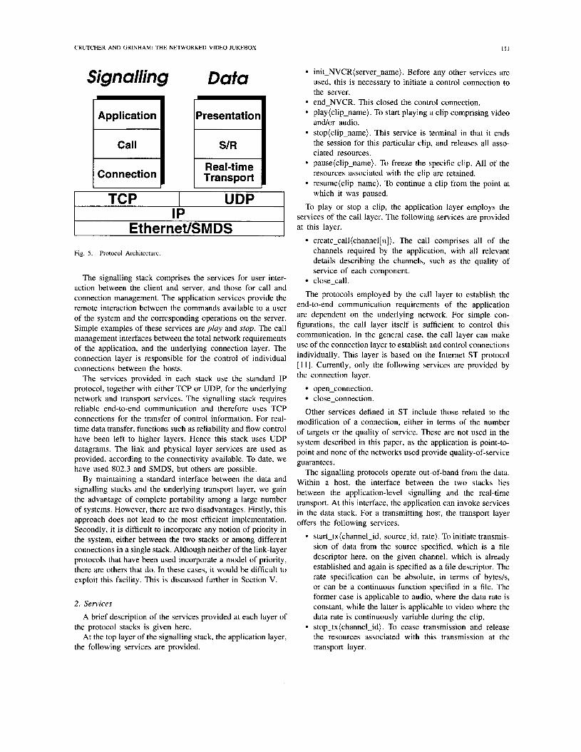
The protocol architecture comprises two stacks, the data stack and the signalling stack, as illustrated in Fig. 5. The data stack is responsible for sending and receiving data in real- time. The signalling stack is responsible for application-level services and connection management.
For real-time data transport, a sending host transmits data at a rate that is specified by the application. This transport layer interfaces to the file system for presentation of data input. To optimally match the data rate and the size of the data units at the presentation layer to those of the underlying network, the segmentation layer may repackage the data where appropriate. A receiver is required to receive the data and to reassemble the data to reconstitute the original data structure. Here, the transport interfaces directly with the video and audio subsystem.
CRUTCHER AND GRINHAM: THE NETWORKED VIDEO JUKEBOX
Signalling Dafa
Application Application
Connect ion
Presentation
Real-time I I
uDq TCP IP
Ethernet/SMDS -1 Fig. 5. Protocol Architecture.
The signalling stack comprises the services for user inter- action between the client and server, and those for call and connection management. The application services provide the remote interaction between the commands available to a user of the system and the corresponding operations 011 the server. Simple examples of these services are play and slop. The call management interfaces between the total network requirements of the application, and the underlying connection layer. The connection layer is responsible for the control of individual connections between the hosts.
The services provided in each stack use the standard IP protocol, together with either TCP or UDP, for the underlying network and transport services. The signalling stack requires reliable end-to-end communication and therefon: uses TCP connections for the transfer of control information. For real- time data transfer, functions such as reliability and flow control have been left to higher layers. Hence this stack uses UDP datagrams. The link and physical layer services are used as provided, according to the connectivity available. To date, we have used 802.3 and SMDS, but others are possible.
By maintaining a standard interface between the data and signalling stacks and the underlying transport layer, we gain the advantage of complete portability among a large number of systems. However, there are two disadvantages. Firstly, this approach does not lead to the most efficient implementation. Secondly, it is difficult to incorporate any notion of priority in the system, either between the two stacks or among different connections in a single stack. Although neither of the link-layer protocols that have been used incorporate a model of priority, there are others that do. In these cases, it would b'e difficult to exploit this facility. This is discussed further in Section V.
2. Services
A brief description of the services provided at each layer of
At the top layer of the signalling stack, the application layer, the protocol stacks is given here.
the following services are provided.
I l l
init-NVCR( server-name). Before any other services are used, this is necessary to initiate a control connection to the server. end-NVCR. This closed the control connection. play(c1ip-name). To start playing a clip comprising video and/or audio. stop(c1ip-name). This service is terminal in that it ends the session for this particular clip, and releases all asso- ciated resources. pause(c1ip-name). To freeze the specific clip. All of the resources associated with the clip are retained. resume(c1ip-name). To continue a clip from the point at which it was paused.
To play or stop a clip, the application layer employs the services of the call layer. The following services are provided at this layer.
create-call(channel[n]). The call comprises all of the channels required by the application, with all relevant details describing the channels, such as the quality of service of each component. close-call.
The protocols employed by the call layer to establish the end-to-end communication requirements of the application are dependent on the underlying network. For simple con- figurations, the call layer itself is sufficient to control this communication. In the general case, the call layer can make use of the connection layer to establish and control connections individually. This layer is based on the Internet ST protocol [ 1 I]. Currently, only the following services are provided by the connection layer.
open-connection. close-connection.
Other services defined in ST include those related to the modification of a connection, either in terms of the number of targets or the quality of service. These are not used in the system described in this paper, as the application is point-to- point and none of the networks used provide quality-of-service guarantees.
The signalling protocols operate out-of-band from the data. Within a host, the interface between the two stacks lies between the application-level signalling and the real-time transport. At this interface, the application can invoke services in the data stack. For a transmitting host, the transport layer offers the following services.
start-tx(channe1-id, source-id, rate). To initiate transmis- sion of data from the source specified, which is a file descriptor here, on the given channel, which is already established and again is specified as a file descriptor. The rate specification can be absolute, in terms of byte&, or can be a continuous function specified in a file. The former case is applicable to audio, where the data rate is constant, while the latter is applicable to video where the data rate is continuously variable during the clip. stop-tx(channe1-id). To cease transmission and release the resources associated with this transmission at the transport layer.
112 IEEE TRANSACTIONS ON CIRCUITS AND SYSTEMS FOR VIDEO TECHNOLOGY, VOL. 4, NO. 2, APRIL 1994
pause-tx(channe1-id). To stop transmitting while retain-
resume-tx(channe1-id) . To continue transmission from
The complimentary receive services are provided by the transport layer on a receiving host. One major difference between the two is that the receiver has no direct control over the data rates so, for a loss-less service, the receiver transport must be able to receive the data at the rate that has been negotiated by the signalling protocols during the set-up of the session. It is a matter for the call-layer protocols to ensure that there are sufficient resources at each end to satisfy the quality of service requested for the clip.
ing the channel resources.
the point at which a pause was issued.
3. Design
The protocols are designed as a set of asynchronously com- municating finite state machines. Each protocol is specified as a data structure comprising an array of states, each state having an array of triples of the form (event, next-state, action). The data structures are interpreted by a state machine executor (SME). The SME is triggered by events that occur in the system. There are four sources of event in the system.
Commands from the user. Information received from the network. Events generated intemally during state machine
Internally generated time-outs. transitions.
The system receives these events in different ways. For example, events resulting from user commands are received via an interface to the windows application while events from the network occur via packets received from the network interface. In all cases the event is translated into a standard format known as a signal. These signals are placed in a single FIFO queue, which is read by the SME.
This design has a regular structure which allows the proto- cols to be easily modified and extended. However, it does not lead to the most efficient implementation in terms of execution time. For this reason, the control path, which includes all of the signalling stack and the interface between this stack and the data stack. has been designed in the way described so far, but some of the indirection has been by-passed in the design of the real-time data path. Once a data channel has been established, there is a direct path of execution from the data source to the network interface on the sending host. Similarly, there is a direct path from the network interface to the video and audio subsystem on the receiving host. Experience with the working system has shown us that this decision was the correct one in order to achieve the required data throughput throughout the system.
For convenience, a menu containing a collection of useful operations has been incorporated into the system. This is usually dormant., but can be activated from the keyboard at any time. The faci1it:ies provided from the menu include the ability for an operator to examine and manipulate the signal queue, and to examine: statistics that are collected during system operation.
make control connection; while (active)
if ((event from windows interface) or (event from network control interface) or (event from internal timers))
translate event to signal; place signal on queue;
remove signal; invoke SME with signal;
for (each active i/p data channels) if (there is any data to be read)
read the data from network channel; pass the data to VA subsystem;
if (signal on queue)
update clock; for (each active o/p data channels)
if (it is time to send some data) read the data from source file; send the data to network channel;
if (keyboard input) invoke menu;
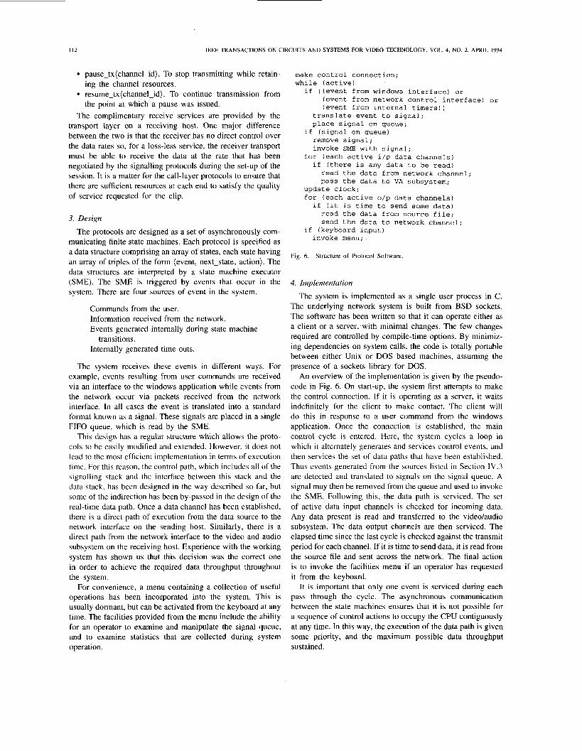
Fig. 6. Structure of Protocol Software.
4. Implementation
The system is implemented as a single user process in C. The underlying network system is built from BSD sockets. The software has been written so that it can operate either as a client or a server, with minimal changes. The few changes required are controlled by compile-time options. By minimiz- ing dependencies on system calls, the code is totally portable between either Unix or DOS based machines, assuming the presence of a sockets library for DOS.
An overview of the implementation is given by the pseudo- code in Fig. 6. On start-up, the system first attempts to make the control connection. If it is operating as a server, it waits indefinitely for the client to make contact. The client will do this in response to a user command from the windows application. Once the connection is established, the main control cycle is entered. Here, the system cycles a loop in which it alternately generates and services control events, and then services the set of data paths that have been established. Thus events generated from the sources listed in Section IV.3 are detected and translated to signals on the signal queue. A signal may then be removed from the queue and used to invoke the SME. Following this, the data path is serviced. The set of active data input channels is checked for incoming data. Any data present is read and transferred to the video/audio subsystem. The data output channels are then serviced. The elapsed time since the last cycle is checked against the transmit period for each channel. If it is time to send data, it is read from the source file and sent across the network. The final action is to invoke the facilities menu if an operator has requested it from the keyboard.
It is important that only one event is serviced during each pass through the cycle. The asynchronous communication between the state machines ensures that it is not possible for a sequence of control actions to occupy the CPU contiguously at any time. In this way, the execution of the data path is given some priority, and the maximum possible data throughput sustained.

CRUTCHER AND GRINHAM: THE NETWORKED VIDEO JUKEBOX
V. EXPERIMENTAL RESULTS To test the system, a clip of approximately 00 seconds
duration, recorded from a film on a laser disk, was played back from the server onto the client. Measurements were taken on the client and the server, and also on a network analyzer attached to the network. A subjective assessment of the quality of the play-back was made through observation of the client.
The recording process allows us to vary the following parameters.
Video compression factor. Audio compression factor. Video frame rate. Video picture size. Number of audio channels (mono/stereo).
Since the parameters related to the video component have a more significant impact on the data rates required a number of recordings of the same clip were made with different values for these parameters but with the same audio settings of stereo with 4 bits/sample on each channel at a sampling rate of 9.45 KHz. The set of clips used are described by the parameters in Table I, which also shows the data rates associated with each clip. Each clip is identified by a name which is constructed as (compression-factor: frame-size: frame-rate), as def ned in the table footnotes.
Detailed timing measurements were taken on the network and the client. The network measurements gave an accurate time stamp for each packet on the Ethernet, together with sufficient information to determine to which video fIame a set of packets relate. The client measurements rezorded the time at which each reassembled frame was transferred to the decompression subsystem. The quality of the clip wits also assessed subjectively, with attention to frame 105s or audio drop-outs, and observable synchronization between vidco and audio.
For local networking, tests were carried out using a single Ethernet segment. Initially, a private segment, on which no other traffic is present, was used. The restriction of using an unloaded network was then relaxed by performing thc same test over a segment of the main Ethernet shared ihroiighout the building. To study the effect of using a network that is not point-to-point, the final tests were carried out with the server attached to a T1 SMDS link, providing communication with the client through an SMDS-802.3 router, again using a shared Ethernet segment in the local area.
In the space available here, we refer to an exmiinalion of the performance of the system using a single clip, q2s2f20, from Table I. In summary, clip q2s2f20 could be succe,sfully played back over each of the three network configurations without any data loss. Subjectively, the quality was judged to be as good as a play back from a local disk, with acceptable synchronization between the video and audio streams. ‘Where the network configuration incorporated the shared Ethemet, this performance was dependent on the volume of other traffic on the segment during play back. Similarly, for the SMDS test, there would be a dependency on the other traffic through the router but for this test no other traffic was allowed as the data rates of the clip were very close to the capacity of the router.
I I3
TABLE I
Mean Mean Clip id frame size video rate Audio rate
(bvtes) (Kbit/s) (Kbit/s) q2‘”2bf20“ 4418 707 76
q2s2f25 4416 883 76 q2s3f20 5614 898 76
q 1 s2f20 6381 1021 76 aq(n) is the compression factor: for this clip, q2 = 0.86 bits/pixel and q l = 1.25 bits/pixel.
hs2 = 236 x 160, s3 = 288 x 192
Cf(n) = R framels.
TABLE I1
Audio Inter-packet time/s Video Inter-packet time/s Network Nominal Mean Var. Nominal Mean Var. Private 0.088 0.092 3.2e-5 0.050 0.050 1.3e-5 LAN Shared 0.088 0.091 2.9e-5 0.050 0.050 1.3e-5 LAN LANlWAN 0.088 0.093 3.k-4 0.050 0.051 4.k-5
TABLE 111
Client Inter Frame Times/s
Network Nominal Mean Variance Private LAN 0.050 0.0496 5.3e-5
Shared LAN 0.050 0.0496 5 3 - 5
Measurements on the network monitor showed that the packet dispersion on the network matched very closely the nominal rates at which the real-time transport was attempting to send data. In all cases there was some jitter about this nominal value, as summarized in Table 11. The corresponding measurements taken on the client are summarized in Table 111. These show a considerable increase in the delay jitter when compared to the network measurements.
For a 60 second clip, we ensured that this jitter had no degrading effect on the play back by incorporating a delay between the arrival of the first data packet on the client and the initiation of the decompression subsystem. This delay allowed the buffer occupancies to reach a level at which the subsequent jitter did not result in data being absent when required by the decompression hardware.
The detailed results of the tests are reported in Sections V. 1-V.3 below. Again, we concentrate on an examination of the single clip q2s2f20.
I . The Private Point-to-point Link
The dispersion of the audio and video packets for a single clip on the private Ethernet segment is shown in Figs. 7 and 8. These graphs show that the packets on each channel are sent according to the nominal rate control with some jitter accumulated between the sending transport process and the physical network. On both the video and audio channels, this jitter is characterized by mainly small, positive and negative, deviations about a mean value which is very close to the

IEEE TRANSACTIONS ON CIRCUITS AND SYSTEMS FOR VIDEO TECHNOLOGY, VOL. 4, NO. 2, APRlL 1994
Network trace for audio packets. private LAN Execution time of read() from audio file
Fig. 7. Dispersion of Audio Packets in Private LAN
Network trace for vdeo packets - private LAN
--I
Dispersion of Video Packets in on Private LAN.
nominal rate at which the data is sent by the transport protocol. This is reflected in the mean value of the measured inter- packet times, which is very close to the nominal value, and the variance of these times, which is very small.
However there are occasional peaks in the graphs that show inter-packet delays that are significantly greater than the nominal time. The source of these occasional anomalies was found by measuring the time taken on the server for the transport process to read data from disk prior to sending a packet. Graphs of these execution times during the whole of the play back period for each of the audio, video, and video index files are shown in Fig. 9. These graphs show that occasionally the execution time of the read() system call is an order of magnitude greater than its mean value. The occurrence of these Iong execution times coincides exactly in time with the anomalous delays on the audio and video packets, so we can conclude that this is the only significant source of jitter in this configuration. There are two possible explanations for the long execution times. Either there is a context switch on the server at these points, or these reads correspond to points where the
I
Execution time of read[) from video file
Execution time of read() from vac file
1 I f I - f 1 l
(C)
Fig. 9 (a)-(c). Disk Read T i m e s on Server.
disk caches are filled. We found that the timing of the behavior illustrated in Fig. 9 was repeated on subsequent play backs of
CRUTCHER AND GRINHAM: THE KETWORKED VIDEO JUKEBOX
Client Trace of InterFrame Times
Start t i ~ t - ?E tcb D? !?:!?:?? C t y ti- - 29 F:t 92 ! ! : !5 :??
I ' r-
U 20 0 40 5cI
Fig. IO. Client Measurement of Video Inter-Frame Time on the Private LAN.
the same clip. This. together with the observation thai. a context switch could occur when other system calls are made but no similar variations in execution time are apparent, leads us to conclude that the jitter is due to the file system caching. The implications of these results are discussed in Section VI.
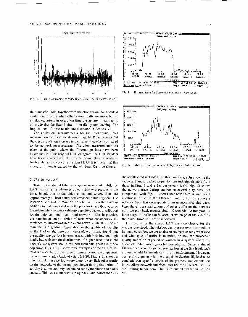
The equivalent measurements for the inter-frame times measured on the client are shown in Fig. 10. It can be seen that there is a significant increase in the frame jitter when compared to the network measurements. The client measurements are taken at the point where the Ethernet packets have been assembled into the original UDP datagram, the UDP headers have been stripped and the original frame data is available for transfer to the codec subsystem FIFO. It is likely that this increase in jitter is caused by the Windows OS time-slicing.
2. The Shared LAN
Tests on the shared Ethernet segment were made whilc the ]LAN was carrying whatever other traffic was present at the time. In addition to the video client and server, there are approximately 40 host computers attached to this segment. The intention here was to monitor the total traffic on the LAN in addition to that associated with the play back, and then observe the relationship between subjective quality, packet distribution for the video and audio, and total network traffic. In practice, the benefits of such a series of tests were considerabli di- minished by limitations in the client network interface.. Rather t,han seeing a gradual degradation in the quality of the clip as the load on the network increased, we instead found that the quality was perfect in some cases, with both low and high loads, but with certain distributions of higher loads the client network subsystem would fail and from this point the v deo clip froze. Figs. 11-1 3 show three examples of the trace of' the total network traffic over a two minute period encompassing the one minute play back of clip q2s2f20. Figure I 1 'Shows a play back during a period where there is very little other traffic o n the network, so the throughput shown during the pzriod of activity is almost entirely accounted for by the video and audio packets. This was a successful play back, and corresponds to
I IS
Fig. 11. Ethernet Trace for Successful Phy Back - Low Load.
Fig. 12. Ethernet Trace for Successful Play Back - Moderare Load.
the results cited in Table 11. In this case the graphs showing the video and audio packet dispersion are indistinguishable from those in Figs. 7 and 8 for the private LAN. Fig. 12 shows the network trace during another successful play back, but comparison with Fig. 11 shows that here there is significant additional traffic on the Ethernet. Finally, Fig. 13 shows a network trace that corresponds to an unsuccessful play back. Here there is a small amount of other traffic on the network until the play back reaches about 40 seconds. At this point, a large surge in traffic can be seen, at which point the video on the client froze and never recovered.
The results for the shared LAN are inconclusive for the reasons described. The jukebox can operate over this medium in many cases, but we are unable to say here exactly what load and what type of traffic is tolerable, or how the subjective quality might be expected to worsen in a system where the client exhibited more graceful degradation. Since a shared Ethernet can never guarantee no data loss at the link level, such a client would be mandatory in this environment. However, our results together with the analysis in Section 111, lead us to conclude that specific details of the protocol implementation in the client network interface, and not the Ethernet itself, is the limiting factor here. This is discussed further in Section VI.
I16 IEEE TKAKSACTIONS ON CIRCUITS AND SYSTEMS FOR VIDEO TECHNOLOGY, VOL. 4, NO. 2, APRIL 1994
%art t i 8 c - 28 Fcb S? 1?:85:!8 Stcp t:rc - 21 Fcb 9! l?:WrlE Msasuranenr tme * 2 illnutes S w l a tine .I i Sccond
I u
1 N
U B I T
P E C
Fig. 13. Ethernet Trace for Unsuccessful Play Back.
Network trace for audio packets - LANMAN connection
0 20 30 0 s$
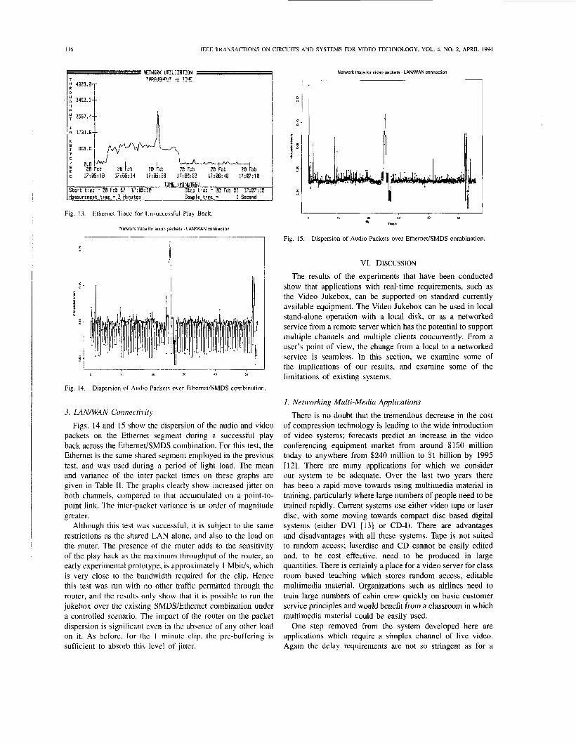
Fig. 14. Dispersion of Audio Packet? ocer Ethernet/SMDS combination
3. LANNAN Connectivitv
Figs. 14 and 15 show the dispersion of the audio and video packets on the Ethernet segment during a successful play back across the EthemedSMDS combination. For this test, the Ethernet is the same shared segment employed in the previous test, and was used during a period of light load. The mean and variance of the inter-packet times on these graphs are given in Table 11. The graphs clearly show increased jitter on both channels, compared to that accumulated on a point-to- point link. The inter-packet variance is an order of magnitude greater.
Although this test was successful, it is subject to the same restrictions as the shared LAN alone, and also to the load on the router. The presence of the router adds to the sensitivity of the play back as the maximum throughput of the router, an early experimental prototype, is approximately 1 Mbit/s, which is very close to the bandwidth required for the clip. Hence this test was run with no other traffic permitted through the router, and the results only show that it is possible to run the jukebox over the existing SMDS/Ethernet combination under a controlled scenario. The impact of the router on the packet dispersion is significant even in the absence of any other load on it. As before. for the 1 minute clip, the pre-buffering is sufficient to absorb this level of jitter.
Network trace tor video packets - L A W A N connection
8 5 -
E E -
8 -
Fig. 15. Dispersion of Audio Packets over EtherneUSMDS combination.
VI. DISCUSSION The results of the experiments that have been conducted
show that applications with real-time requirements, such as the Video Jukebox, can be supported on standard currently available equipment. The Video Jukebox can be used in local stand-alone operation with a local disk, or as a networked service from a remote server which has the potential to support multiple channels and multiple clients concurrently. From a user's point of view, the change from a local to a networked service is seamless. In this section, we examine some of the implications of our results, and examine some of the limitations of existing systems.
1. Networking Multi-Media Applications
There is no doubt that the tremendous decrease in the cost of compression technology is leading to the wide introduction of video systems; forecasts predict an increase in the video conferencing equipment market from around $150 million today to anywhere from $240 million to $1 billion by 1995 [12]. There are many applications for which we consider our system to be adequate. Over the last two years there has been a rapid move towards using multimedia material in training, particularly where large numbers of people need to be trained rapidly. Current systems use either video tape or laser disc, with some moving towards compact disc based digital systems (either DVI [13] or CD-I). There are advantages and disadvantages with all these systems. Tape is not suited to random access; laserdisc and CD cannot be easily edited and, to be cost effective, need to be produced in large quantities. There is certainly a place for a video server for class room based teaching which stores random access, editable multimedia material. Organizations such as airlines need to train large numbers of cabin crew quickly on basic customer service principles and would benefit from a classroom in which multimedia material could be easily used.
One step removed from the system developed here are applications which require a simplex channel of live video. Again the delay requirements are not so stringent as for a

CRUTCHER AND GRINHAM: THE NETWORKED VIDEO JUKEBOX I I 7
two way video conference and many people have proposed that such a service could have wide applicability. In particular remote support, maintenance, and monitoring of anything from power stations to aeroplanes is an interesting area. Airlines have a requirernent for such a system to help reduce aircraft downtime caused by unscheduled maintenance at airports where they do not have a service depot.
There are three main factors that need to be addreqsed in extending our prototype into a robust and versatile system.
Presence of other traffic, particularly over a WAN. Multiple clients using a single server. Extension to applications having more stringent real-time
These have consequences for the transport and network
l.A. Video and Audio Transport Real-time data transport is essential to support video and
audio streams. One of our initial experiments with the Video Jukebox used a request-response model for data transport, based on TCP. In this system, the client would request data from the server at times initiated by the codec, and the server would respond by sending this data over a TCP connection. This approach was successful in very limited circumstances, but generally exhibited poor performance. By placing the source of timing in the server and using this to drive a rate-controlled transport layer, we can achieve more a:: l u r a t e - timing and higlher throughput.
For a system like the Video Jukebox, the existing prsotocols will be adequate for operation in many situations. Consid- eration of the factors listed above shows that there are two areas where we could usefully enhance the existing protocol. Firstly, the rate control should be extended to operate in a burst mode. It is not possible in practice to send data at a constant mean rate with total precision. Inaccuracies occur from the source timing itself, and are also introduced by other variable delays in the server. The jitter resulting from the disk access on the server for a single clip could be minimized, by contiguous file placement for example, but this would reappear if the server had multiple clients viewing different clips simultaneously. A file system that is designed to support real-time data streams, as described in [14] for example. will help but it is not possible to eliminate jitter throughout the entire system so the rate control should be extended so that variable delays can be accommodated. It is difficult for the transport to accommodate jitter within the network, which is addressed in the next section, but for the other sources, a variable transport data rate can absorb the jitter. T i e rate specification should include a nominal rate, corresponding to the mean data rate of the channel, with the addition of a higher rate that can be used periodically when the actual data rate on the channel has not matched this nominal rate. (Note also that a more adaptive rate control mechanism may dso be appropriate to support data sources that are more bursty by nature. MPEG-compressed video could be an example of this type of source.)
Knowing when to switch data rates is the second area for enhancement. In a limited well-controlled environment,
demands, !such as two-way video communication.
layers, as described below.
where the types of delay expected are known in advance, the switching period can be set a priori. This was in fact done on the video jukebox to achieve the same effect as the pre-buffering employed. This approach is fragile as it takes no account of the actual behavior of the channel on the network and in the client. A more satisfactory solution is to incorporate feedback from the client to the server giving the server knowledge of the actual data rates being achieved and the level of buffer occupancy. The transport can then adjust dynamically to maintain the real-time requirements of the channel. This type of facility is analogous to window-based flow control such as that employed in TCP, but with the timing under the direct control of the source, and feedback provided only when adjustments are required to this timing.
We also need to reconsider the requirements in order to support multi-media applications other than the video jukebox. Meeting the real-time requirements of the jukebox is eased by the fact that there is no interaction between client and server on the data paths. This gives 1.1s the scope to use pre- buffering on the client to overcome jitter on the data channels. Some applications, such as multi-media conferencing, are multi-way and interactive and would therefore not permit this technique to be used. Those applications will place much more stringent demands on the network layer to meet the real-time requirements, as discussed further below.
These extensions to the transport layer mean that the pro- tocol incorporates many of the features contained in some of the proposals that have emerged for a new standard transport layer in future high-speed networks. Examples include XTP and VMTP. Some of these protocols also include support for multicast, which is a useful feature for applications requiring multipoint distribution. There is currently no consensus on the relative merits of these candidates, and little practical experience in using them on real networks, but i t is likely that one or more of these protocols will form an integral component of future networked multimedia systems.
1 .B. Networks ,fiw Video c ind Air&) A more adaptive transport protocol of the type described
above may not be sufficient to maintain real-time channels in a general network environment, particularly where the channels have harder real-time demands than those for the jukebox. Jitter due to the network is not easy to predict, particularly over networks that are not point-to-point, and especially over large WANs. Reports on the load on the Internet, for example, show highly variable levels of congestion with corresponding variations in delay. In the general case where a user wishes to operate any time at any location. it highlights the requirement for support for real-time data at the network level in addition to higher levels. There are two ways of by-passing this problem.
Exclude other traffic from the network. Dedicating a segment of the network to the real-time application is a short-term solution that will enable a limited number of users to operate. Use a network that has some support for synchronous channels. FDDI is one candidate. ISDN could be used for connection over the wider area.

118 IEEE TRANSACTIONS ON CIRCUITS AND SYSTEMS FOR VIDEO TECHNOLOGY. VOL. 4. NO 2 . APRIL 1994
The first approach may be an acceptable way of introduc- ing multi-media applications such as the video jukebox to selected users, and for gaining exposure for the benefits of these systems. It has obvious limitations in terms of cost, convenience, and connectivity. The second approach provides a number of potential platforms, particularly in the wide area. It is currently unclear in which direction the public service providers will move, and it is certain that developments here will be influenced as much by political and economic factors as they will by technical considerations. See [I51 for further insight into the options available here. Our interest in this paper is bringing real-time services to computer users now, so we focus on the use of the large existing base of conventional packet-mode networks. The Internet for example provides huge global connectivity, and is still expanding. Further, packet-mode operation has the attraction of economy and scalability, and is in some ways more appropriate for applications requiring multicast, which is likely to be an important facility in many multi-media applications. For ap- plications displaying bursty traffic characteristics, isochronous channels are not necessarily appropriate anyway, and can lead to inefficient use of network resources. With extensions to the network layer, existing packet networks can be used to support real-time channels without the restrictions imposed during our tests. Enhancements are required in two areas.
Resource reservation. Dynamic resource control.
The requirement for reservation is illustrated by the tests on the EthernetEMDS network. In this case, the bandwidth required by a clip is close to the total capacity of the router. It is necessary to negotiate with components such as the router to claim the resources required during a session, and to incor- porate resource control mechanisms within these components that ensure that a quality-of-service that is negotiated is indeed fulfilled. A signalling protocol for this purpose is defined by the existing ST-I1 standard, and this has been incorporated into the protocol architecture of the video jukebox. How- ever, there are currently few implementations in commercially available routers of the resource control required at the IP level.
The use of a shared Ethernet for local connectivity has some limitations. The non-deterministic access in Ethernet means that users will always be subject to some loss of data. Alternative technologies, such as Token Ring, provide more deterministic performance and therefore may be considered a more suitable base for this application. However, as already noted, the characteristics of the video traffic are not necessarily suited to this type of access. Further, some data loss is tolerable, and the nature of the MAC protocol in Ethernet is such that rather than losing a lot of data, it is more common that data is just delayed during periods of high load. With a more adaptive transport protocol, and perhaps with larger buffers on the client, it is likely that a fair of degree of tolerance to this delay can be built into the system.
We believe that the behavior of our system during unsuc- cessful playback on the shared Ethernet is not an inherent
limitation of the Ethemet, but a result of some specific details of the implementation of the networking software in the client. A ‘‘lost’’ Ethemet frame, which results in a partially assembled UDP packet in the client, together with the implementation of the timing in the PC network software, can lead to a temporary deadlock of the type observed during unsuccessful playback. The required behavior, for this application, in the presence of an unreliable link layer is for the client to discard data within a very short time (determined by the application) if it cannot be successfully received, so that subsequent video frames can be received. We would expect to observe no more than occasional loss of a video frame in this case. With the software available to us, we were unable to experiment with such changes. This is an example of where specific details of protocol implementation, targeted at conventional data transfer, are not allbays appropriate for exchange of real- time data such as video.
The future promises to deliver higher speed networks in both the local and wide area, based on cell technology such as ATM. The efficient multiplexing of traffic on these networks provides the potential for bandwidth on demand, and widens the scope for networked multimedia. (The articles in [ 161 give a good overview of future trends in multimedia communication.) These networks however introduce difficulties of their own, in that the end-to-end protocols have to handle periodic cell loss. Note also, that high-speed networks in general present a different performance characteristic in their latencyhandwidth parameter which fundamentally changes the way in which protocols need to operate. These problems are still at the point of research, and we do not discuss them further here. See [ 17 I for an introduction.
2. Video and Audio Subsystems
The video and audio subsystems used for this work were prototypes originally developed in 199 I by Videologic to ex- plore operation from a local disk. We have found that operation over a network introduces some different requirements for these subsystems. As an example, one such requirement is in the data transfer process to the cards. With the prototype system it was necessary to pass whole frames of video data to the compression card. It could not reassemble fragmented frames. This causes problems because the underlying data transport was UDP datagrams. The average frame size was around 4 KBytes which was transferred as a single datagram which after encapsulation by UDP and IP is roughly 3 4 times the maximum transfer unit (MTU) on Ethemet. As a result the frame is fragmented into a number of packets which are transmitted back to back on the network. These packets are then reassembled into the original datagram by the client’s network subsystem before the whole datagram is read into a user buffer on the client.
In order to reduce this bursty transmission of Ethernet frames, which can lead to frame loss in the receiving host, it would be useful to fragment the original video frame into a number of datagrams. Each datagram would correspond to a single network packet and the individual packet transmission onto the network could then be controlled by the server. This

CRUTCHER AND GRINHAM: THE NETWORKED VIDEO JUKEBOX I19
means that at the client at some point these individual packets must be reassembled into the original frames. The current interface between the host and the compression subsystem forces this to be done on the host before the data transfer to the compression cards. Given by the load on the host machine processor it would be useful to explore whether this reassembly could be better done on the compression subsystem control processor.
Another area which has not been explicitly addressed so far is the synchronization of source and sink clock rates and the synchronization of separate video and audio streams. The source and sink sample clock rate problem can be tackled by modifying the effective display time of a sample or frame to compensate for the differing sample rates [ 181. One possible mechanism for doing this is to monitor the receive FIFO depth and use this to modify the playout time of buffered frames or samples, in a manner similar to a phase locked loop, or indeed a similar loop could be used to control the playout clock frequency itself. Alternatively end system clocks could be synchronized by the use of NTP (Network Time Protocol) [19], though there are obviously cases where this might be impractical, such as between separate organizations.
As noted earlier, the video and audio in this system are not linked by timestamps or other means, so both relative sample clock drift or data loss on either channel will cause the synchronization to slip. Many of these issues of terminal synchronization and stream synchronization are being :onsid- ered as part of RTP, the real-time transport protocol, which is currently an Internet Draft document and the reader is referred there for further discussion [20].
A final point concerns the compression algorithms and media quality used in this system. As has been noted earlier the video was compressed using the JPEG algorithm which was originally developed for compression of full color still images [2 I]. The development of single chip implementations of this algorithm has enabled it to be used at rates up to 30 framedsecond, and has led to its use as a video coding algorithm 1221. The disadvantage of this algorithm compared to MPEG or H.'261 [23] is that it makes no use of the temporal redundancy of successive frames. This makes the algorithm considerably leijs efficient. Typical figures suggest ithat MPEG gains a factor of 3 in the overall compression of many image sequences for an equivalent image quality [4].
The video sequences used in our experiments were dis- played as 1/4 screen VGA at 20 fps in full color. At the bit rate used the image quality was slightly worse than VHS video when viewed a.t typical computer screen distances. Whether this image quality is adequate depends very much on the application, but certainly for some applications mentioned, such as general purpose training, it would be sufficient. One area that needs further research is the ability to develop image quality metrics that can be related to applications requirements.
The audio quality could probably best be described ;is high end AM radio quality, though we did run the audio in stereo which gave the impression that it was closer to FM radio quality even though the sample rate used was only 9.45 kHz. Again it is difficult to relate this to applications requirements, but it was perfectly adequate to replay the film soundtrack.
3. Disk Technology
Disk technology is one area of concern if the video jukebox application, or related applications such as video mail, are to become viable in the near future. Parallel access to multiple stored video streams, or multiple random access to a single stream incurs significant overheads as the read heads track from one section of the disk to another. This greatly reduces the maximum possible rate that can be sustained off the disk, as was shown in Section 111.
This problem of disk rates is not however exclusive to multimedia applications. Over the last decade the processing power of single chip CPUs has grown at 50-60%, per year while dynamic disk performance has merely doubled. As a result there is considerable activity throughout the industry aimed at improving disk performance. Many companies are considering multiple disk array subsystems, or developing disks with multiple active read heads. There is also the possibility of low cost solid state FLASH disks appearing over the next few years. This implies it should be possible to develop relatively low cost video servers capable of delivering multiple streams during the mid to late 1990's.
VII. CONCLUS[ONS
This work reported in this paper has shown that it is possible to build networked video and audio systems using standard equipment that is available off-the-shelf. As expected there are limitations in this approach. These are in the data rates and the number of users that can be supported, and the classes of application that can be provided. However, within these limits, video compression technology has given us the capability to provide some networked multimedia services now. The experiments conducted have highlighted the areas where further progress is required, either to support applications with real-time interaction or to provide higher data rates. We conclude by stating these areas among our general observations below.
It is not necessary to use an isochronous network to carry networked video and audio. Conventional packet-based networks can be used to support many multimedia appli- cations, althouh some work is required in the protocols used, and the precise implementation of these protocols. In some ways. these networks are better suited to the application, particularly when the data streams are bursty, as with compressed video for example. The system characteristics required to replay stored video and audio. particularly end-to-end delay and delay jitter, are much less stringent than those required for real- time full duplex video conferencing. The best opportunity in the near term for developing multimedia products integrated with conventional computer syslems is with applications dependent on the replay of stored video, not those requiring real-time full duplex conferencing. There are many system design issues that arise when com- pressed isochronous data is brought into a conventional computer system. These problems become much more acute if the system is networked.

I20 IEEE TRANSACTIOW ON CIRCUITS AND SYSTEMS FOR VIDEO TECHNOLOGY, VOL. 4, NO. 2, APRIL 1994
In the future, we seek disk throughput as being a greater limitation than network bandwidth. Thus, it will be nec- essary to provide specialized disks, or disk arrays, for a server to support a large number of data channels simultaneously. It is a requirement to provide real-time transport for multi- media applications. However, the overhead of protocol processing is not significant. It is not necessary to pro- vide custom hardware for this purpose. Applications that require multicast may prove more of a problem in this respect. The reduction in data rates achieved just through the use of JPEG hardware means that bandwidth requirements of a limited number of users of a real-time system such as the video jukebox can be met by existing networks. Of greater importance than the total bandwidth in the network is the mechanisms provided for resource allocation.
[3 1
[41
[51
161
REFERENCES
G. Clapp, “LAN Interconnection across SMDs,” IEEE Network, vol. 5 , no. 5, pp. 25-32, 1991. W. D. Sincoskie, “System Architecture for a Large Scale Video on Demand Service,” Computer Netuorks ond ISDN Systems, vol. 22, pp. 155-162, 1991. P. V. Rangan et al., “Designing an On-Demand Multimedia Service,” fEEE Communications Magazine, vol. 30, no. 7, pp. 56-64, 1992. Communications of the ACM, vol. 34. no. 4, 1991. Special issue on Digital Multimedia Systems. CCIR Recommendation 7 17, “Tolerances for transmission time differ- ences between the vision and sound components of a television signul,” Dusseldorf, 1990. R. Gussella, “The analysis of diskless workstiition trafic on un ethernet. ” UCB/CSD 87/379. Computer Science Division, University of California- Berkeley, November 1987. D. Boggs et al., “Measured Capacity of dr? Ethernet: Myths and Reality.” Proceedings ACM SIGCOMM-88, pp. 222-234, 1988. S. Minzer, “A Signalling Protocol for Complex Multimedia Services.” fEEE J. o n Selected Areas in Commun., vol. 9, no. 9, pp. 1383-1394, 1991.
[9] L. Crutcher k G. Waters, “Connection Management for ATM Net- works.” fEEE Network, vol. 6 , no. 6, pp. 42-55, November 1992.
[IO] W. Doeringer et al., “A survey of light-weight transport protocols for high-speed networks,” IEEE Truns. on Commun., vol. 38, no. 11, pp.
[ I I] C. Topolcic (ed.), “Experimental Intemet Stream Protocol, version 2 (ST-11)”. RFC 1190, October 1990.
[ 121 J. Johnson. “Video Conferencing,” Data Communications, Nov. 1991. [ 131 G. D. Ripley, “DVI-A Digital Multimedia Technology,” Communica-
tions of thr ACM, vol. 32, no. 7, pp. 81 1-822, 1989. (141 P. V. Rangan k H. M. Vin, “Designing file systems for digital video
and audio,” Operating Systems Review’, vol. 25, no. 5 , pp. 81-94, 1991.
2025-2039, 1990.
1231
J. Sutherland 9i L. Litteral, “Residential video services,” IEEE Commu- nications Magazine, vol. 30, no. 7, pp. 3 W 1 , 1992. IEEE Communications Magazine, vol. 30, no. 5, 1992, Special issue on Multimedia Communication. L. Kleinrock, “The latencyhandwidth tradeoff in gigabit networks,” IEEE Communications Magazine, vol. 30, no. 4, pp. 3 6 4 0 , 1992. W. Montgomery, ‘Techniques for packet voice synchronization,’’ IEEE J. on Selected Areas in Commun., vol. I , no. 6, Dec. 1983. D. L. Mills, “Network Time Protocol (version 3)-specification, imple- mentation and analysis,” Internet RFC 1305, Mar. 1992. H. Schulzrinne, “A transport protocol for audio and video conferences and other multiparticipant real-time applications,” fETF Intemer Drarfr Document, Oct. 1992. ISO/IEC JTCIISC2TWG IO, “Digital compression and coding of continuous-tone still images,” Draft 1991. B. Szabo k G. Wallace, “Design considerations for JPEG video and synchronized audio in a Unix workstation environment,” Usenix Sumnier 1991 Proceedings, pp. 353-368. N. D. Kenyon & C. Nightingale, “AudioVisual telecommunications,” BT Telecommunication Series, Chapman and Hall, 1992.
Laurence Crutcher (M’90) received the B.Sc (1985) and Ph.D (1989) degrees from the University of Bristol, UK. At the University of Bristol, he carried out research into computer architectures for the implementation of communication protocols, and lectured in the fields of computer architecture , real-time systems, and communication systems. In 1989, he joined Hewlett Packard Laboratories, where he carried out work in a number of areas in the Network Technology Group. This included work on protocols for high-speed networks, and protocols
to carry real-time traffic over standard networks. In 1992, he joined the Center for Telecommunications Research at Columbia University, where he worked on network control and management for Gigabit networks. Since September 1993, he has been a software engineer at Market Vision, New York, NY. His research interests include multimedia systemsand network architecture and protocols.
John Grinham received the B.Sc (1984) degree from the University of Bristol, UK. Between 1984 and 1986 he worked on optical signal processing techniques at Cossor Electronics. In 1986, he joined Hewlett Packard Laboratories. Here he has carried out work in a number of areas within the Network Technology Group, and is currently working on networks and systems for multimedia applications.
4