the motion decoupled delivery system: a new … · the motion decoupled delivery system: a new...
TRANSCRIPT
Scientific Drilling, No. 15, March 2013 51
The Motion Decoupled Delivery System: A New Deployment System for Downhole Tools is Tested at the New Jersey Margin
doi:10.2204/iodp.sd.15.07.2013
Technical Development
by Peter B. Flemings, Peter J. Polito, Thomas L. Pettigrew, Gerardo J. Iturrino, Eric Meissner, Robert Aduddell, Donald L. Brooks, Chris Hetmaniak, David Huey, John T. Germaine, and
the IODP Expedition 342 Scientists
Overview
The Motion Decoupled Hydraulic Delivery System (MDHDS) is a new downhole tool delivery system that is deployed by wireline and uses drillstring pressure to ad-vance a penetrometer (or other downhole tool) into the for-mation at the bottom of offshore boreholes. After hydraulic deployment of the penetrometer, it is completely decoupled from the BHA; this eliminates the adverse effects of ship heave. We tested the MDHDS at Site U1402 (the location of Site 1073, ODP Leg 174A), offshore New Jersey, during two days of ship time during Integrated Ocean Drilling Program (IODP) Expedition 342. In one deployment we emplaced a penetrometer successfully and documented that it was decoupled from drillstring movement. Based on this successful field test, the MDHDS has been certified by the U.S. Implementing Organization (USIO) for ship-board use. The MDHDS will replace the previous deploy-ment system, the Colletted Delivery System. The MDHDS is an IODP-funded engineering development led by The University of Texas at Austin, in conjunction with the USIO and Stress Engineering Services. This sea trial was the cul-mination of a seven-year development effort that included extensive engineering design and fabrication.
Introduction
We make downhole measurements in the IODP with 1) wireline logging or logging-while-drilling (LWD) tools that profile the borehole, 2) permanent observatories at the sea-floor, and 3) downhole tools that interact with the formation at specific depths. Wireline logging or LWD is used through-out the drilling program to measure physical properties and for interpreting everything from formation pressure (Moore et al., 1995) to sedimentology and climate change (Hesselbo, 1996). We generally rely on oil field service company pro-ducts for logging. However, tools also have been developed specifically for deployment within the IODP (Goldberg et al., 2004). Over the last two decades, we have made extraordi-nary investments in borehole observatories to measure geo-chemical and hydrological properties (Becker and Davis, 2005). Finally, we have a limited number of downhole tools that make measurements at specific depths when a borehole is drilled. The Advanced Piston Corer Temperature tool (APCT) and the Sediment Temperature tool (SET), pre-viously known as the Davis-Villinger Temperature Probe
(DVTP), are used to take temperature measurements. The Sediment Temperature Pressure tool (SET-P), previously known as the Davis-Villinger Temperature Pressure Probe (DVTP-P), the Temperature Two Pressure probe (T2P), and the Piezoprobe are used to take pressure measurements in semi-consolidated rocks. More recently, with the use of wide diameter drillpipe or riser drilling system, we have also begun to make direct pressure and stress measurements with the Modular Formation Dynamics Tester (MDT) of Schlumberger (Boutt et al., 2012; Lin et al., 2010).
The SET, SET-P, Piezoprobe, and T2P are borehole penetrom-eters. They are low-ered down the borehole inside the drill pipe to the bottom of the bore-hole and driven verti-cally downwards by the weight of the drillstring into the formation. The SET records the fric-tional heating that results when the tool is driven in and the sub-sequent temperature dissipation; in situ tem-perature and the ther-mal diffusivity can be derived from these data. The SET-P, Piezoprobe, and T2P record pore pressure during insertion and during subsequent dis-sipation from which the in situ pressure and the coefficient of consoli-dation can be derived. The SET-P and T2P also record tempera-ture. The SET-P was deployed during ODP Legs 190, 201, and 204 (D’Hondt et al., 2003; Moore et al., 2001;
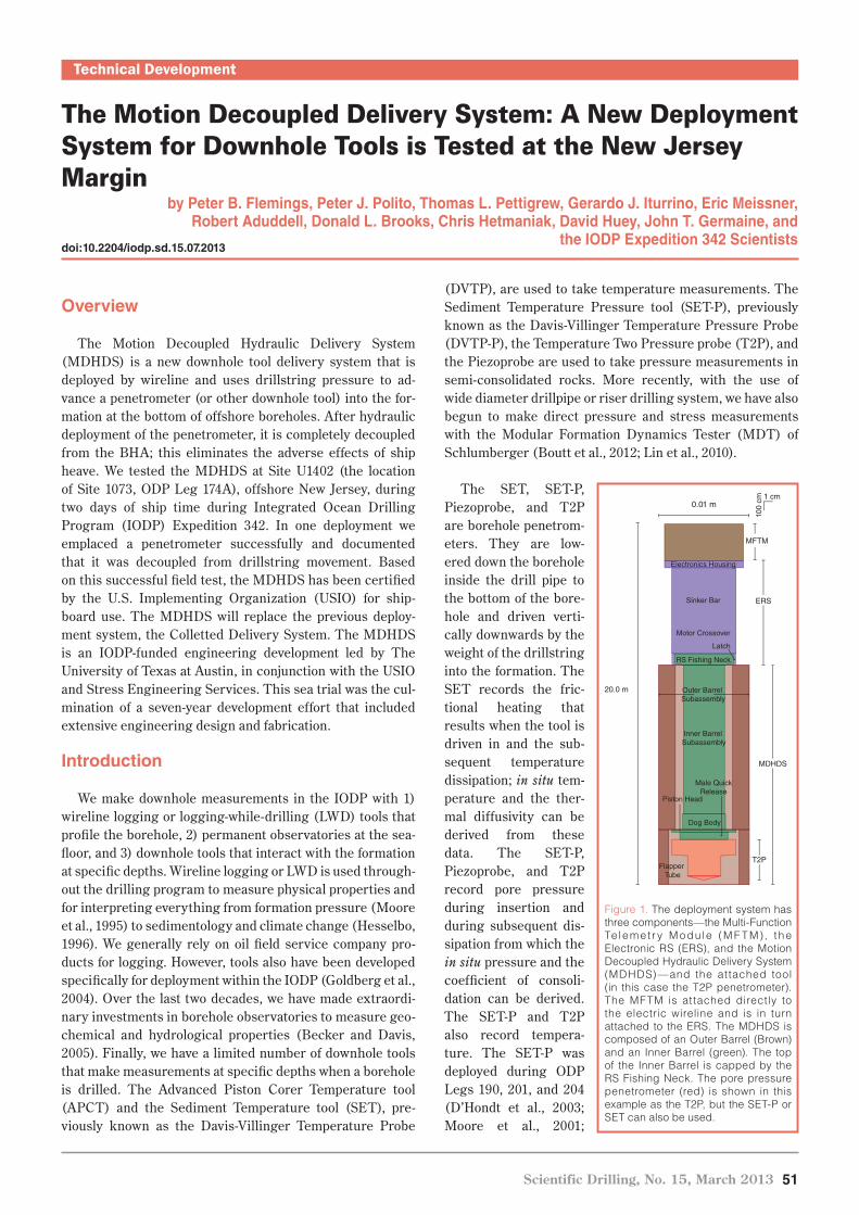
Figure 1. The deployment system has three components—the Multi-Function Te lemet r y M odu le (M F T M), the Electronic RS (ERS), and the Motion Decoupled Hydraulic Delivery System (MDHDS)—and the at tached tool (in this case the T2P penetrometer). The MFTM is attached directly to the electric wireline and is in turn attached to the ERS. The MDHDS is composed of an Outer Barrel (Brown) and an Inner Barrel (green). The top of the Inner Barrel is capped by the RS Fishing Neck. The pore pressure penetrometer (red) is shown in this example as the T2P, but the SET-P or SET can also be used.
MFTM
ERS
1 cm
100
cm0.01 m
20.0 m
MDHDS
T2P
Electronics Housing
Sinker Bar
Motor Crossover
Latch
RS Fishing Neck
Inner Barrel Subassembly
Dog Body
Piston Head
Male QuickRelease
Outer Barrel Subassembly
Flapper Tube

52 Scientific Drilling, No.15, March 2013
Technical Development
Decoupled Hydraulic Delivery System (MDHDS). This wireline-deployed system uses drillstring pressure to advance a penetrometer into the formation. After hydraulic deployment of the penetrometer, it is completely decoupled from the BHA to eliminate the adverse effects of ship heave. We completed three separate land tests at Schlumberger’s Sugarland Test Facility and numerous other bench-top tests at Stress Engineering Services, LDEO, and The University of Texas at Austin. In June 2012, we held a final field test on the JOIDES Resolution during IODP Expedition 342. A full description of this engineering development is available (Shipboard Scientific Party, 2013). We summarize the MDHDS development and the final field test at Site U1302 below.
The New Deployment System
The MDHDS is part of a three-component system (Fig. 1). The Multi-Function Telemetry Module (MFTM) allows real-time communication with the ERS and other tools. The Electronic “RS” (the ERS; “RS” is an oil field designation for a particular geometry of fishing tool) delivers and retrieves the MDHDS and the attached downhole tool to the Bottom Hole Assembly (BHA). The MDHDS, once seated in the BHA, is the platform from which the penetrometer (or some tool to be designed in the future) is deployed.
Tréhu et al., 2003). The Piezoprobe was deployed during ODP Leg 204 (Long et al., 2007), whereas the DVTP-P and T2P were deployed during IODP Expedition 308 (Flemings et al., 2005, 2008; Long et al., 2008).
The ability to measure in situ pressure and tem-perature rapidly and at multiple depths during an expedition provides an important capability to address problems described in the new IODP Science Plan. These measurements allow us to map heat and fluid flow, provide valuable constraints for analyzing climate change, and help in our under-standing of the Earth’s dynamic systems, which are themes within the 2013–2023 IODP Science Plan. For example, we can determine slope stability (when and how submarine landslides form), inter-pret whether recent warming has occurred from the temperature profile, and illuminate how pore pres-sure impacts deformation in convergent margins.
Although penetrometer deployments in the IODP have yielded exciting results, they have also been challenging because the penetrometer is often dislodged from the formation. During IODP Exp. 308, in more than half of all deployments—and in all deployments at less than 100 mbsf—the pene-trometer was dislodged (Flemings et al., 2008). Uncoupling is recorded by a rapid drop in the measured pressure and by tool movement (recorded by the accelerometer) when the BHA is raised after the penetrom-eter is inserted. This compromises the measurement of in situ pressure. The DVTP-P pressure records from Legs 201 and 204 also show that tool dislodgement has been a persis-tent problem (D’Hondt et al., 2003; Tréhu et al., 2003). In addition, when a narrow diameter penetrometer such as the T2P is used, the tip is often bent or destroyed, either because the tool is poorly aligned when it is pushed into the formation or because it is bent when it passes through the flapper valve at the drill bit (Flemings et al., 2006).
The T2P and SET-P penetrometers have been deployed by wireline on the Colleted Delivery System (CDS). The CDS is analogous to an old-style pointer, in which a series of cylinders slide past each other to increase or decrease the system’s length. In this configuration, the penetrometer is pushed into the formation by the drillstring, and then the drillstring is raised several meters. Decoupling of the drill-string from the penetrometer is achieved by the expansion and contraction of the CDS. We attribute the dislodgement of the penetrometer to be due to friction within the CDS that pulls the penetrometer out when the drillstring is raised, or to “swabbing” (the suction induced by raising the drill-string).
In 2005 we began a seven-year project to design, build, and test a new deployment system called the Motion
Figure 2. [A] The Inner Barrel Subassembly (IBS) and the Outer Barrel Subassembly (OBS). [B] Left: the IBS lies inside the OBS. The fishing neck of the IBS is shown on the lower left. Right: the ERS is connected to the MFTM, which is connected to the logging line. The ERS Latch is at the bottom of the ERS assembly. [C] The MDHDS Latch and latching tool. The latch is set on the rig floor, and this fixes the IBS to the OBS. When the drillstring is pressurized, this latch is released, and the IBS slides freely from the OBS. [D] The SET-P and the T2P are two pore pressure penetrometers available for use in the drilling program.
A B
CD
Inner Barrel Subassembly (IBS)
Outer Barrel Subassembly (OBS)
MDHDS latch
MDHDS latch
MDHDS latchingtool
T2P
OBS
IBS
Tether
ERS latch
ERS
MFTM
RS �shing neck
SET-P
Scientific Drilling, No. 15, March 2013 53
Technical Development
Multi-Function Telemetry Module (MFTM)
The MFTM (Fig. 1) is a downhole sonde that allows real-time communication with downhole tools through the Schlumberger armored 7-conductor cable. The MFTM was developed by the Lamont-Doherty Earth Observatory (LDEO) Borehole Research Group, and it is used to activate the latching of the ERS and to capture data streams from probes attached to the inner core barrel of the MDHDS assembly.
Electronic RS (ERS) System
The ERS tool (Figs. 1, 2) was developed for use with the Simple Cabled Instrument for Measuring Parameter In-situ (SCIMPI) system, and the MDHDS. The ERS deploys and retrieves the MDHDS (or any downhole tool) within the drill-pipe on the electric wireline. The ERS has a snap-lock and is latched at the surface; the tool is low-ered into the borehole, where an electric motor within the ERS is commanded from the surface to rotate until the RS pulling neck on the downhole instrument is released. This motor can unlock the ERS from the down-hole tool and return the ERS to a locked position so that it can be used to retrieve the downhole tool. The ERS consists of an electronics section, wired through sinker bars, and a motor section that contains the latching mechanism at the bottom of the tool. A prototype of the ERS was used on IODP Expedition 327 to successfully deploy the Hole U1301B CORK system (Expedition 327 Scientists, 2011).
The Motion Decoupled Hydraulic Delivery System
The MDHDS is composed of an Inner Barrel Subassembly (IBS, Figs. 1, 2a), an Outer Barrel Subassembly (OBS, Fig. 1), and the MDHDS Latch. The penetrometer is attach-ed to the IBS. On the rig floor, before the MDHDS is deployed, the IBS is latched to the OBS. The latching system (MDHDS Latch), near the bottom of the MDHDS (Fig. 1), is cocked by shifting a latch piston, compressing a spring within the MDHDS Latch, and then shifting an internal sleeve to lock the latch piston in place (Fig. 2c). The internal sleeve is then held in place by shear pins. The latched MDHDS is conveyed by wireline by the ERS to sit on the landing shoulder of the standard BHA. The MDHDS Latch is activated by raising the drillstring pressure. This severs the two shear pins, which allow the internal sleeve to move, unlocking the latch piston, which remains held in place by the drillstring pressure. Relieving the drillstring pressure allows the spring to expand, moving the latch piston, and opening the latch. The IBS is then freed from the OBS.
The IBS and penetrometer is then pumped into the forma-tion by raising the drillstring pressure. When using a narrow diam-eter penetrometer like the T2P, the bottom of the MDHDS can be outfitted with a flapper guide tube. This tube protects the penetrometer as it passes through the flapper at the drill bit and acts as a guide to ensure vertical deploy-ment. For larger diameter penetrometers like the SET-P, the flapper guide tube is not used.
During this test, we installed a tension device inside the IBS to house a communications tether. The tether allowed real-time communication from the penetrometer to the rig floor. This tension device—consisting of a rigid and elastic cable and a series of pulleys—held the communications tether in tension at all times, taking up slack as the drill-string heaved downward and letting it out as it heaved upward. The tether connected to the top of the T2P and the bottom of the ERS.
Deployment Procedure
The MDHDS is first latched at the rig floor (Fig. 2c). The penetrometer is then attached to the bottom of the IBS. The MDHDS and the penetrometer are then hung vertically on the rig floor in the drillpipe. The cable head, MFTM, and ERS assembly are then snap-locked to the IBS, and the MDHDS is lowered on the electric wireline. The MDHDS is landed in the BHA with the BHA positioned 1.5 m above the bottom of the hole (Fig. 3a).
The MFTM actuates the ERS to unlatch the MDHDS, and the ERS is raised 3 m (Fig. 3b). With the MDHDS
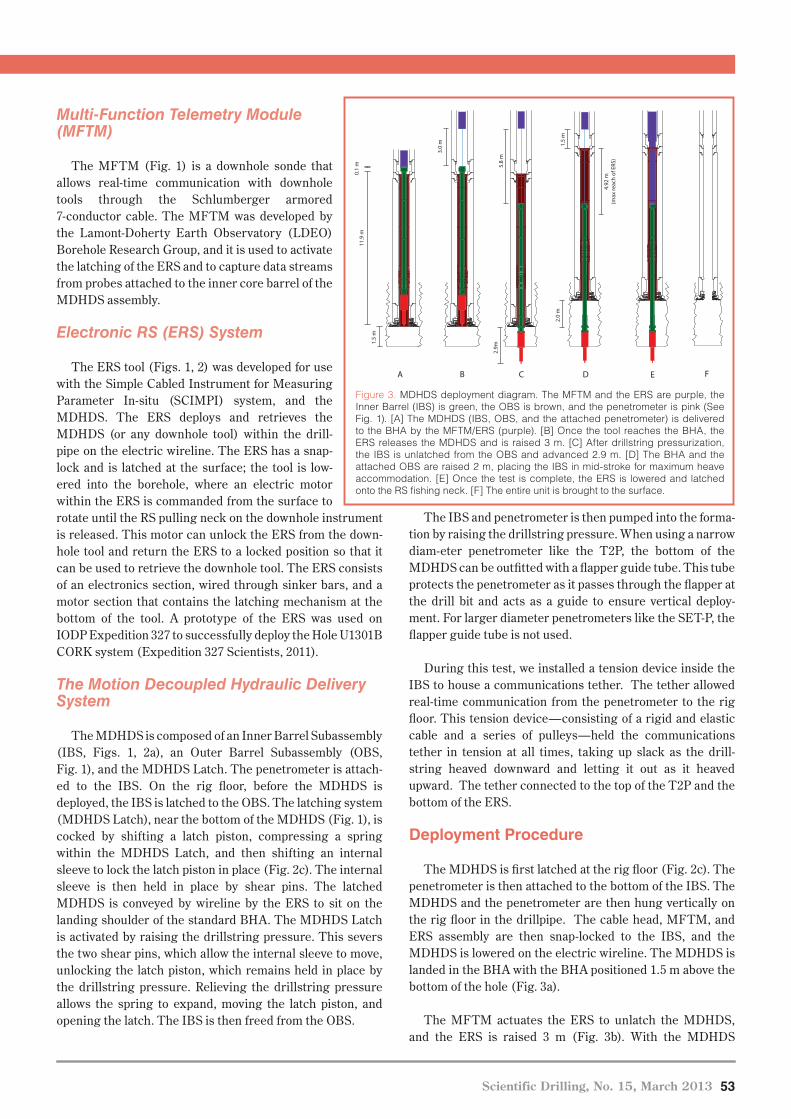
Figure 3. MDHDS deployment diagram. The MFTM and the ERS are purple, the Inner Barrel (IBS) is green, the OBS is brown, and the penetrometer is pink (See Fig. 1). [A] The MDHDS (IBS, OBS, and the attached penetrometer) is delivered to the BHA by the MFTM/ERS (purple). [B] Once the tool reaches the BHA, the ERS releases the MDHDS and is raised 3 m. [C] After drillstring pressurization, the IBS is unlatched from the OBS and advanced 2.9 m. [D] The BHA and the attached OBS are raised 2 m, placing the IBS in mid-stroke for maximum heave accommodation. [E] Once the test is complete, the ERS is lowered and latched onto the RS fishing neck. [F] The entire unit is brought to the surface.
A B C D E F
11.9
m
1.5
m
3.0
m
5.8
m2.
9m
2.0
m
0.1
m
1.5
m
4.92
m(m
ax re
ach
of E
RS)

54 Scientific Drilling, No.15, March 2013
Technical Development
latched and landed in the BHA, all the drillstring fluid is forced through the center of the OBS through a contact seal between the MDHDS landing shoulder and the wall of the BHA. Next, the drillstring is slowly pressurized to approxi-mately 8 MPa (1160 psi) and held for several minutes to actuate the latch mechanism. Pressure is then released and, upon pressure reduction, the latch is opened. Next, the drill-string is re-pressurized, and the probe is pumped into the formation (Fig. 3c). The probe can be driven a maximum of 2.9 m because after that a circulation path is established and there is no longer any driving pressure. The BHA is then raised 2 m (Fig. 3d), allowing for +/- 2.5 m of vertical motion. At this point in the deployment, the OBS is fixed relative to the BHA, and the IBS is fixed relative to the bottom of the hole. There are no seals in contact between the IBS and OBS; thus, no seal friction exists that could induce heave motion into the probe.
The probe is extracted by using the MFTM for actuating the ERS into a closed position, lowering the MFTM-ERS assembly until latching with the RS fishing neck that is attached to the IBS (Fig. 3e). The probe is then pulled from the formation into the OBS (Fig. 3f), where it is well protect-ed during the trip out of the hole. If the probe is embedded so firmly into the formation that the wireline cannot lift, then the BHA can be raised to dislodge the probe from the bottom.
The MDHDS is retrieved by wireline. On deck, it is laid out as a normal core barrel would be. The flapper tube is removed to allow access to the T2P, which is then detached from the IBS by disconnecting a quick-release connection.
The MDHDS latch is then reset in preparation for the next deployment.
Site U1402 Deployment
At Site U1402, the continental slope is smooth, draped by sediments from the Hudson River apron, and the water depth is 639 m. During ODP Leg 174A, Advanced Piston Cores (APC) were taken to 215 mbsf (meters below sea floor). Sediments within the first 200 mbsf were dominated by silty clay (Shipboard Scientific Party, 1998).
The new hole at the previous Site 1073 was named Site U1402 and was spudded on 7 June 2012. The seafloor was recorded at 650 meters below rig floor (mbrf). The hole was washed down to 96.4 mbsf (746.4 mbrf), and the MDHDS, T2P, and the ERS were assembled and deployed. The MDHDS was lowered by the ERS to the BHA. The ERS was unlatched with the tether system in place and raised two meters above the BHA. The drillstring pressure was raised, and the T2P penetrometer was deployed (Fig. 4).
After the MDHDS Latch was released, the T2P and IRS passed through the BHA and into the formation under their own weight, driving the tip of the T2P into the formation, but not far enough to drive the shaft pressure port into the for-mation (Fig. 4, Pt. A). After we increased the drillstring pres-sure a second time, the entire tool was driven approximately 2.9 m farther into the formation until circulation was esta-blished (Fig. 4, Pt. B). Between Points C and D (Fig. 4), cir-culation was maintained, and pore pressure varied but de-clined slightly. At Pt. D, the pumps were shut off, and the
pressure data recorded a dissipation characteri-stic of a penetrometer deployment.
When circulation was re-established to clear the BHA of settled sediment, the tool jammed. The ERS was released and the wireline was pulled from the hole; the top drive was then set back, and the drillstring was tripped from the hole. After drillpipe retrieval, we found that the tether within the IBS had snapped and worked between the tool and the inside of the BHA aperture, jamming the tool in place and preventing recovery.
Interpretation of Results
The MFTM, ERS, and MDHDS worked well in this deployment. The IBS and T2P successfully unlatched and were deployed after drillstring pressurization (Fig. 4, Pt. A). When the drill string was re-pressurized, the penetrometer was suc-cessfully driven into the formation (Fig. 4, Pt. B). After penetration, both the tip and shaft pressure sensors recorded smooth pressure dissipation profiles. The lack of any motion in the accelerom-eter (green triangles, Fig. 4) during the dissipa-
Figure 4. MDHDS deployment record. Zero time is set to the onset of pressure dissipation. At Pt. A (-400 s), the MDHDS latch is released, and the IBS and the attached T2P descend by gravity driving the tip a small distance into the formation. As a result, the tip pressure (blue) and the shaft pressure (red) rise abruptly. The accelerometer (green) records rapid changes in acceleration. At Pt. B, the drillstring is re-pressurized, and the penetrometer is driven into the formation (e.g., Fig. 3c). At Pt. C, we interpret that the penetrometer has been driven the maximum 2.9 m of stroke that is possible (Fig. 3c). Between Pt. C and Pt. D, there is ongoing circulation but no longer any significant driving force. At Pt. D, the circulation pumps are turned off, and pressure dissipation begins.
500 0 500 1000 1500 2000
Acceleration (g
)
0.8
0.9
1.0
1.1
1.2
1.3
1.4
Pres
sure
(MPa
)
7.0
7.5
8.0
8.5
9.0
9.5
10.0
A
BC
D
Shaft Pressure
Acceleration
Tip Pressure
Hydrostatic Pressure
Adjusted time (s)

Scientific Drilling, No. 15, March 2013 55
Technical Development
tion interval is evidence that the drillstring completely decoupled from the penetrometer. Finally, the penetrometer was undamaged when it was recovered, which indicates that it was driven straight downward and that there were no pro-blems with the flapper valve at the bottom of the BHA.
The pressure records are characteristic of those recorded by successful T2P deployments (Flemings et al., 2008). The shaft pressure (Fig. 4) is higher than the tip pressure because the larger diameter shaft induced a larger pore pressure during penetration. The pressure rebound re- corded at the tip (0–50 seconds, Fig. 4) is due to the unloading that resulted when circulation stopped. Extrapolation of the tip pore pressure record (Fig. 5, inset) results in a predicted in situ pressure of 7.54 MPa (blue square, Fig. 5), which is slightly above hydrostatic pressure. Similar results were predicted by Dugan and Flemings (2000) based on an indirect measurement with respect to bulk density.
Long-Term Application
Based on the outcome of this engineering test, the MDHDS, the T2P, and MFTM have been certified for deployment on board the JOIDES Resolution. Although real-time data were acquired through the tethered system, failure of the tether during drillstring pressurization shows that a tethered real-time telemetry configuration is not ready for regular shipboard use. Stress Engineering Services is completing final modifications to the ERS to improve its latching operation. Once the modifications are complete, this tool will also be certified for onboard deployment by USIO. The ERS will be used to deploy the SCIMPI during
IODP Expedition 331S in May of 2013. We hope that the advances in tool delivery allowed by the MDHDS will result in rich pore pressure and temperature data sets in future expeditions and will engender the development of new down-hole tools that can be deployed by the MDHDS.
Acknowledgements
We thank the entire crew of Expedition 342, especially the electronics technician, machinists, engineers, and the drilling crew. We express our gratitude to the crew on the Schlumberger Genesis Rig where much of the land-based testing took place. Additionally, we are indebted to Michael Meiring, Yoshi Kawamura, Eddie Wheeler, Dean Ferrell, Tessa Green, David Braley, and James Piper. Support for this work came from an IODP Engineering Development Grant, the Jackson School of Geosciences, the U.S. Science Support Program, and the UT GeoFluids Consortium. This project was managed by the University of Texas at Austin with parti-cipation from Stress Engineering Services, Pettigrew Engineering, the Borehole Research Group at Lamont-Doherty Earth Observatory (LDEO), and the Engineering Services Group at Texas A&M.
The IODP Expedition 342 Scientists
R.D. Norris (Co-chief Scientist), P.A. Wilson (Co-chief Scientist), P. Blum (Expedition Project Manager/Staff Scientist), A. Fehr, C. Agnini, A. Bornemann, S. Boulila, P.R. Bown, C. Cournede, O. Friedrich, A.K. Ghosh, C.J. Hollis, P.M. Hull, K. Jo, C.K. Junium, M. Kaneko, D. Liebrand, P.C. Lippert, Z. Liu, H. Matsui, K. Moriya, H. Nishi, B.N. Opdyke, D. Penman, B. Romans, H.D. Scher, P. Sexton, H. Takagi, S.K. Turner, J.H. Whiteside, T. Yamaguchi, Y. Yamamoto
References
Becker, K., and Davis, E. E., 2005. A review of CORK designs and
operations during the Ocean Drilling Program. In Fisher,
A. T., Urabe, T., Klaus, A., and the Expedition 301 Scientists,
Proc. IODP, 301: Washington, DC (Integrated Ocean
Drilling Program Management International, Inc.).
doi:10.2204/iodp.proc.301.104.2005
Boutt, D. F., Saffer, D., Doan, M.- L., Lin, W., Ito, T., Kano, Y.,
Flemings, P. B., et al., 2012. Scale dependence of in situ
permeability measurements in the Nankai accretionary
prism: The role of fractures. Geophys. Res. Lett., 39:L07302.
doi:10.1029/2012GL051216
D’Hondt, S. L., Jørgensen, B. B., Miller, D. J., et al., 2003. Proc. ODP,
Init. Repts., 201: College Station, TX (Ocean Drilling
Program), [CD-ROM].
Dugan, B., and Flemings, P. B., 2000. Overpressure and fluid flow in
the New Jersey continental slope: Implications for slope fail-
ure and cold seeps. Science, 289(5477):288–291. doi:10.1126/
science.289.5477.288
Expedition 327 Scientists, 2011. Expedition 327 summary, In Fisher,
A. T., Tsuji, T., Petronotis, K., and the Expedition 327
Figure 5. Pressure/stress vs. depth plot at Site U1302. The overburden stress is interpreted from Site 1073 density data (Shipboard Scientific Party, 1998). The in situ pore pressure, as extrapolated from the tip pressure (inset) is interpreted to be 7.54 MPa. Inset: a plot of tip and shaft pressure vs. the inverse square root of time. For both the tip and the shaft pressure, the pressure is extrapolated linearly to zero-time to estimate the in-situ pressure (e.g. Flemings et al., 2008).
Pressure (MPa)
6.0 7.0 8.0 9.0 10.0 11.0
Dep
th (
mbs
l)
600
650
700
750
800
850
Adjusted time
0.000 0.005 0.010 0.015 0.020 0.025 0.030
Pre
ssur
e (M
Pa)
7.2
7.4
7.6
7.8
8.0
8.2
8.4
8.6
Projected In
Situ Pressu
re (Shaft)
Projected In Situ Pressure (Tip)
Shaft Pressure
Tip Pressure
Overburden Pressure
Hydrostatic Pressure
U1402 In Situ Pressure
(s )-1/2

56 Scientific Drilling, No.15, March 2013
Technical Development
Scientists, Proc. IODP, 327: Washington, DC (Integrated
Ocean Drilling Program Management International, Inc.).
doi:10.2204/iodp.proc.327.101.2011
Flemings, P. B., Behrmann, J., Davies, T., John, C., and the Expedition
308 Project Team, 2005. Gulf of Mexico hydrogeology—
overpressure and fluid flow processes in the deepwater Gulf
of Mexico: Slope stability, seeps, and shallow-water flow.
IODP Sci. Prosp., 308. doi:10.2204/ iodp.sp.308.2005
Flemings, P. B., Behrmann, J., John, C. M., and the Expedition 308
Scientists, 2006. Proc. IODP, 308: Washington, DC
(Integrated Ocean Drilling Program Management
International, Inc.). doi:10.2204/iodp.proc.308.2006
Flemings, P. B., Long, H., Dugan, B., Germaine, J., John, C. M.,
Behrmann, J. H., and Sawyer, D., 2008. Erratum to “Pore
pressure penetrometers document high overpressure near
the seafloor where multiple submarine landslides have
occurred on the continental slope, offshore Louisiana, Gulf
of Mexico” [Earth and Planetary Science Letters 269/3–4
(2008) 309–32]. Earth Planet. Sci. Lett., 274(1–2):269–283.
doi:10.1016/j.epsl.2008.06.027
Goldberg, D., Meltser, A., Myers, G., and Masterson, W., 2004.
Comparison of Multi-Sensor Spectral Gamma Ray Tool
(MGT) and conventional spectral gamma ray logs, ODP
Site 1179. Proc. ODP, Sci. Results, 191: College Station, TX
(Ocean Drilling Program).
Hesselbo, S. P., 1996. Proc. ODP, Sci. Results, 150: College Station, TX
(Ocean Drilling Program).
Lin, W., Doan, M.- L., Moore, J. C., McNeill, L., Byrne, T. B., Ito, T.,
Saffer, D., et al., 2010. Present-day principal horizontal
stress orientations in the Kumano forearc basin of the
southwest Japan subduction zone determined from IODP
NanTroSEIZE drilling Site C0009. Geophys. Res. Lett.,
37:L13303. doi:10.1029/2010GL043158
Long, H., Flemings, P. B., and Germaine, J. T., 2007. Interpreting in
situ pressure and hydraulic properties with borehole pene-
trometers in ocean drilling: DVTPP and Piezoprobe deploy-
ments at southern Hydrate Ridge, offshore Oregon. J.
Geophys. Res., 112:B04101. doi:10.1029/2005JB004165
Long, H., Flemings, P. B., Dugan, B., Germaine, J. T., and Ferrell, D.,
2008. Data report: Penetrometer measurements of in situ
temperature and pressure, IODP Expedition 308. In
Flemings, P. B., Behrmann, J. H., John, C. M., and the
Expedition 308 Scientists, Proc. IODP, 308: Washington, DC
(Integrated Ocean Drilling Program Management
International, Inc.). doi:10.2204/iodp.proc.308.203.2008
Moore, G. F., Taira, A., Bangs, N. L., Kuramoto, S., Shipley, T. H.,
Alex, C. M., Gulick, S. S., et al., 2001. Structural setting of
the Leg 190 Muroto Transect. In Moore, G.F., Taira, A.,
Klaus, A., et al., Proc. ODP, Init. Repts., 190:College Station,
TX (Ocean Drilling Program), [CD-ROM].
Moore, J. C., Shipley, T. H., Goldberg, D., Ogawa, Y., Filice, F., Fisher,
A., Jurado, M. J., et al., 1995. Abnormal fluid pressures
and fault-zone dilation in the Barbados accretionary
prism: Evidence from logging while drilling. Geology,
23(7):605–608. doi:10.1130/0091-7613(1995)023<0605:AFP
AFZ>2.3.CO;2
Shipboard Scientific Party, 1998. Site 1073. In Austin, Jr., J. A.,
Christie-Blick, N., Malone, M. J., et al., Proc. ODP, Init.
Repts., 174A: College Station, TX (Ocean Drilling Program),
153–191. doi:10.2973/odp.proc.ir.174a.105.1998
Shipboard Scientific Party, in press. Site 342. In Norris, R., Wilson, P.,
and Blum, P., Proc. ODP, Init. Repts., 211: College Station,
TX (Ocean Drilling Program).
Tréhu, A. M., Bohrmann, G., Rack, F. R., and Torres, M. E., 2003.
Proc. ODP, Init. Repts., 204: College Station, TX (Ocean
Drilling Program). doi:10.2973/odp.proc.ir.204.102.2003
Authors
Peter B. Flemings, Peter J. Polito, and Donald L. Brooks, Jackson School of Geosciences, The University of Texas at Austin, 1 University Station C1100, Austin, TX 78712-0254, U.S.A., e-mail: [email protected], [email protected], [email protected] L. Pettigrew, Pettigrew Engineering, 479 Nine Mile Road, Milam TX 75959, U.S.A., e-mail:[email protected] J. Iturrino, and Eric Meissner, Borehole Research Group, Lamont-Doherty Earth Observatory of Columbia University, P.O. Box 1000, 61 Route 9W, Palisades, NY 10964, U.S.A., e-mail:[email protected], [email protected] Aduddell, Integrated Ocean Drilling Program, Texas A&M University, 1000 Discovery Drive, College Station, TX 77845-9547, U.S.A., e-mail:[email protected] Hetmaniak, and David Huey, Stress Engineering Services, 13800 Westfair East Drive Houston, TX 77041, U.S.A., e-mail:[email protected], [email protected] T. Germaine, Department of Civil and Environmental Engineering, Massachusetts Institute of Technology, Cambridge, MA 02139, U.S.A., e-mail:[email protected] and the IODP Expedition 342 Scientists
Photo Credits
Fig. 2a−c: Peter Flemings, The Unicersity of Texas at AustinFig. 2d: William Crawford, IODP-TAMU
Related Web Links
http://www.iodp.org/Science-Plan-for-2013-2023/http://www.ig.utexas.edu/research/facilities/downhole/mdhds.htm