the metrology system of the vlti instrument gravity · the metrology system of the vlti instrument...
TRANSCRIPT

The metrology system of the VLTI instrument GRAVITY
Magdalena Lippaa, Stefan Gillessena, Nicolas Blindb, Yipting Kokc, Senol Yazıcıa, JohannesWebera, Oliver Pfuhla, Marcus Hauga, Stefan Kellnera, Ekkehard Wieprechta, Frank
Eisenhauera, Reinhard Genzela, Oliver Hansa, Frank Haußmanna, David Hubera, TobiasKratschmanna, Thomas Otta, Markus Plattnera, Christian Raua, Eckhard Sturma, Idel
Waisberga, Erich Wiezorreka, Guy Perrind, Karine Perraute, Wolfgang Brandnerf, ChristianStraubmeierg, and Antonio Amorimh
aMax Planck Institute for Extraterrestrial Physics (MPE), Giessenbachstr. 1, 85748 Garching,Germany
bUniversite de Geneve, 24 rue du General-Dufour, 1211 Geneve 4, SwitzerlandcThe University of Western Australia, 35 Stirling Highway, Perth WA 6009, Australia
dObservatoire de Paris/LESIA, 61 Av. de l’Observatoire, 75 014 Paris, FranceeIPAG, 414 Rue de la Piscine, Domaine universitaire, 38 400 Saint Martin d’Heres, France
fMPIA Heidelberg, Konigstuhl 17, 69117 Heidelberg, GermanygUniv. Cologne, Zulpicher Str. 77, 50937 Koln, Germany
hSIM FCUL, Edifıcio C8, gab 8.5.12, 1749-016 Lisboa, Portugal
Copyright 2016 Society of Photo-Optical Instrumentation Engineers. One print or electronic copy may be made for
personal use only. Systematic reproduction and distribution, duplication of any material in this paper for a fee or for
commercial purposes, or modification of the content of the paper are prohibited.
ABSTRACT
The VLTI instrument GRAVITY combines the beams from four telescopes and provides phase-referenced imagingas well as precision-astrometry of order 10 µas by observing two celestial objects in dual-field mode. Theirangular separation can be determined from their differential OPD (dOPD) when the internal dOPDs in theinterferometer are known. Here, we present the general overview of the novel metrology system which performsthese measurements. The metrology consists of a three-beam laser system and a homodyne detection schemefor three-beam interference using phase-shifting interferometry in combination with lock-in amplifiers. Via thisapproach the metrology system measures dOPDs on a nanometer-level.
Keywords: GRAVITY, metrology, interferometry, VLTI, phase shifting, narrow-angle astrometry
1. INTRODUCTION
GRAVITY combines the beams from four telescopes interferometrically and provides high-resolution imaging aswell as narrow-angle astrometry together with spectroscopic and polarimetric capabilities. For phase-referencedimaging and precision-astrometry of order 10 µas, this adaptive-optics assisted beam combiner (BC) observestwo celestial objects simultaneously in dual-field mode. In this way, GRAVITY will revolutionize dynamicalmeasurements of astronomical targets. In particular, its primary science goal is to probe physics in the GalacticCenter close to the event horizon of the supermassive black hole, where certain effects predicted by the theoryof general relativity are expected to take place. For this purpose, GRAVITY consists of three main components:the infrared wavefront sensors, the actual beam combiner instrument (BCI) and the laser metrology system. Thelatter determines the differential optical path difference (dOPD) between the science and the reference objectresulting from their angular separation on sky. To that end, the metrology system measures internal dOPDswithin the interferometer and subtracts them from the measured dOPDs between the targets to extract their
Further author information:Magdalena Lippa: E-mail: [email protected]
arX
iv:1
608.
0488
8v1
[as
tro-
ph.I
M]
17
Aug
201
6

dOPD on sky. Here, we present the general concept of the metrology which consists of a three-beam laser systeminjected via fiber optics to the BCI of GRAVITY and a homodyne detection scheme for three-beam interferenceusing phase-shifting interferometry. In more detail, the metrology measures the phases of laser fringe patternscreated in the pupil planes of the telescopes, from which the internal dOPDs can be derived. The developedsystem fulfills the following physical requirements:
• all beams of the interferometer are monitored in parallel,
• the total length of the instrument and the VLTI up to the primary space is covered by thesystem, which is the correct position for defining the astrometric baseline,
• the phases are measured with a nanometer-accuracy,
• the differential delay lines (DDLs) can be closed stably on basis of the metrology signal,
• the phases are tracked at a speed fast enough during the acquisition procedure, such thatpresetting times are not excessive.
Subsequently, we describe the working principle of the metrology system followed by its implementation and afew concluding remarks.
2. WORKING PRINCIPLE
The working principle of the metrology system is demonstrated in Figure 1. The metrology traces all the opticalpaths from the beam combination of the astronomical light back to the telescopes. Since its measurements coverthe full path of the instrument and the VLTI up to the primary mirror M1 and are performed in the pupil planeat fixed positions with respect to M1 after reflection on the latter, the definition of the astrometric narrow-anglebaselines is essentially free of systematics.1 In addition, the pupil is sampled at typical radii such that potentialsystematics due to differential focus is eliminated.The basic concept is to split laser light into three beams with fixed phase relations. Two of the beams arefaint and injected backwards into the two BCs of the celestial objects. The third, high-power beam is overlaidon top of the two faint ones after they have passed fibers within the BCI. This approach is chosen in order tominimize inelastic scattering of the metrology light in the instrument fibers, which is backscattered onto thescience detector. In more detail, fluorescence of the rare earth elements Holmium (Ho3+) and Thulium (Tm3+)as well as Raman emission in fluoride fibers, both excited by the metrology laser wavelength, can be observed inthe detector band.Another advantage of this three-beam implementation is the suppression of non-common path effects from vari-ations of high-power laser radiation. Their origin lies in the injection of the metrology light to the BCs whichintroduces optical paths that the science light does not travel, therefore the term “non-common”. A certain partof these paths appears in the astrometric error budget and should not drift more than a few nanometers duringan observation block. However, high laser powers can induce temperature fluctuations in the metrology injectionfibers which result in variations of the fiber length implying such drifts.2
At telescope level, the three light beams interfere in the pupil plane and form a fringe pattern which in principlecarries the individual interferences between three beams. Temporal sampling of this fringe pattern with photodi-odes allows for extracting the phase corresponding to the internal dOPD between the light paths of the referenceand science object from one telescope. The phase of interest corresponds to the one of the interference betweenthe faint beams which alone would be undetectably faint. Therefore, the third beam serves as an amplificationfor the fringe pattern. This is why, for the actual measurement of the phase between the faint beams, we analyzetheir individual interference with the third beam independently by phase-shifting each of them with a character-istic frequency. By means of lock-in amplifiers referenced to those frequencies the phases of the correspondingfringes can be extracted and in difference provide the desired internal dOPD between science and reference pathwhile the phase of the high-power beam cancels out. Since we are only interested in the oscillating terms ofthe interference carrying the phase information, the AC signal, and not the average level of the oscillation, themetrology receivers are AC-coupled. This realization corresponds to a homodyne detection scheme in the sensethat the lock-in amplifiers use the frequencies with which the metrology signals are modulated as reference.

Figure 1. Working principle of the metrology system shown for two out of four telescopes. Laser light is split into equallyfaint beams and one high-power carrier beam. The faint beams are injected backwards into the BCs A and B of the twoobserved objects A and B. The carrier beam is split and superimposed to enhance the faint signal for detection. Thebeams trace the optical paths of the astronomical light back to the telescope pupils T1 and T2 where they interfere. Forthe homodyne detection each of the two faint beams is phase-shifted with an individual frequency. Lock-in amplifiersare coupled to each of the frequencies in order to disentangle the two fringe patterns between the faint beams and thecarrier at each telescope. Subtracting the respective fringe phases from each other cancels out the carrier phase suchthat the actual fringe phase of interest between the faint beams is retrieved. The dOPD within the interferometer can bedetermined from the phase difference between the telescopes.

Knowing the internal dOPDs for two telescopes encoded in the phases Φ1 and Φ2 allows for calculating thedOPD on sky between the observed objects as seen by this baseline from the difference of the astronomical fringephases ΨA and ΨB measured on detector A and B via
dOPD =λA2π
ΨA − λB2π
ΨB +λL2π
(Φ2 − Φ1) − λL2π
(δ2 − δ1) . (1)
This formula includes the effective wavelengths of the light of star A and B, λA and λB , as well as the wavelengthof the metrology laser λL. In total, six baselines between four telescopes are addressed in that way. Thecontributions δ1 and δ2 denote the non-common path terms in the metrology injection which need to be calibratedfor the data reduction3 by swapping the light of two nearby stars between the BCs in order to determine thezero points of the metrology phases. These measurements are not performed online but in the preset of anobservation.
3. IMPLEMENTATION
The final system design consists of three main parts, namely the injection of the metrology laser light into theBCI, its detection in the latter and at telescope level as well as of the computing hardware and software. TheGRAVITY software was presented in Reference 4 and 5 while this contribution focuses on the other aspects. Theimplemented hardware is sketched in Figure 2 and the corresponding components are listed in Table 1. Here, wediscuss selected key items.
3.1 Laser
The stabilized single frequency laser source from Menlo Systems produces light at a wavelength slightly belowthe astronomical K-band of 2.0 µm to 2.5 µm and has the following properties:
• power output: > 1 W at the end of a 30 m long fiber,
• output wavelength: 1908 nm ± 1 nm, stabilized to ±30 MHz absolute wavelength accuracy,
• FWHM of the output wavelength distribution < 10 MHz,
• degree of linear polarization: > 100 : 1 at fiber output,
• polarization direction adjusted to slow axis of fiber and fiber connector key,
• power output fluctuations (at the end of the 30 m fiber): < 0.5% RMS of the integrated laser power overa 30 ms timescale,
• total residual optical power, outside of the range 1907 nm ≤ λ ≤ 1909 nm: < 10−4 of total output power.
3.2 Phase shifters
The Photline phase shifters are electro-optic devices employing lithium niobate (LiNbO3) crystals in which achange of refractive index can be induced by applying a voltage. Since this material is highly birefringent i. e. ithas two transmission axes with different refractive indices, the linear polarized optical input should be aligned toone of these axes to maintain the linear polarization of the laser light otherwise elliptical polarization would beintroduced when feeding both axes. However, due to many fiber connections in between the phase modulatorsand the laser source small misalignments can occur in the setup presented here. As a consequence, we splicedfiber polarizers from Thorlabs to the in- and output fibers of the phase shifters in order to correct for possiblemismatches in front of and behind the devices. We apply two different phase-modulating frequencies for thescience and reference metrology beam, both in the kilohertz-range.

Figure 2. Sketch of the metrology hardware. For detailed description see Table 1 and the text.
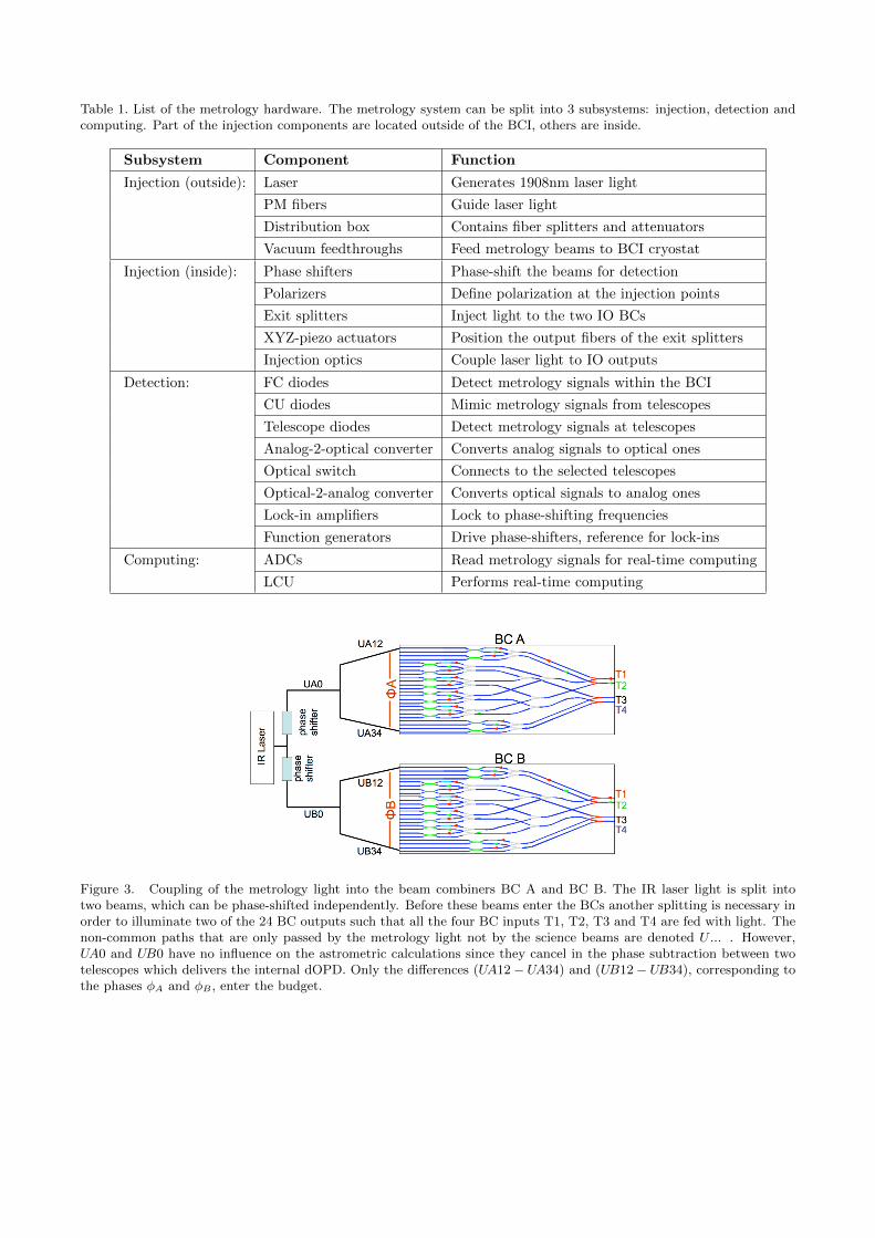
Table 1. List of the metrology hardware. The metrology system can be split into 3 subsystems: injection, detection andcomputing. Part of the injection components are located outside of the BCI, others are inside.
Subsystem Component Function
Injection (outside): Laser Generates 1908nm laser light
PM fibers Guide laser light
Distribution box Contains fiber splitters and attenuators
Vacuum feedthroughs Feed metrology beams to BCI cryostat
Injection (inside): Phase shifters Phase-shift the beams for detection
Polarizers Define polarization at the injection points
Exit splitters Inject light to the two IO BCs
XYZ-piezo actuators Position the output fibers of the exit splitters
Injection optics Couple laser light to IO outputs
Detection: FC diodes Detect metrology signals within the BCI
CU diodes Mimic metrology signals from telescopes
Telescope diodes Detect metrology signals at telescopes
Analog-2-optical converter Converts analog signals to optical ones
Optical switch Connects to the selected telescopes
Optical-2-analog converter Converts optical signals to analog ones
Lock-in amplifiers Lock to phase-shifting frequencies
Function generators Drive phase-shifters, reference for lock-ins
Computing: ADCs Read metrology signals for real-time computing
LCU Performs real-time computing
Figure 3. Coupling of the metrology light into the beam combiners BC A and BC B. The IR laser light is split intotwo beams, which can be phase-shifted independently. Before these beams enter the BCs another splitting is necessary inorder to illuminate two of the 24 BC outputs such that all the four BC inputs T1, T2, T3 and T4 are fed with light. Thenon-common paths that are only passed by the metrology light not by the science beams are denoted U ... . However,UA0 and UB0 have no influence on the astrometric calculations since they cancel in the phase subtraction between twotelescopes which delivers the internal dOPD. Only the differences (UA12 − UA34) and (UB12 − UB34), corresponding tothe phases φA and φB , enter the budget.

3.3 Fiber positioner units
From this point the metrology light enters the two custom-made fiber positioner units which couple the laserbeams to the BCs which are realized as integrated optics6 (IO). In order to send light to all four telescopes, twoof the 24 IO outputs (6 baselines x 4 phases = 24) need to be illuminated as demonstrated in Figure 3. For thisreason the two beams are split again into two of equal intensity by means of LEONI fiber splitters which wedenote as exit splitters. Their output fibers, not connectorized but cleaved, are glued into v-grooves on xyz-piezoactuators from SmarAct such that each fiber can be aligned remotely to the desired IO output via free-beamcoupling optics. The positioning accuracy and the maximum position drift are smaller than 0.05 µm.In order to minimize non-common path effects to a negligible level of the error budget the output fibers are keptas short as possible (≈ 5 cm) and their maximum difference in length is 1 mm. Furthermore, those fibers aresingle-mode (SM) but not polarization-maintaining (PM) in contrast to the other parts of the metrology chainincluding the input fibers of the exit splitter. This design leads to smaller changes of the output polarizationstate from bending of the fibers by actuators than for PM fibers as shown in laboratory tests. The short SMfibers maintain the polarization state nevertheless because their beat length is much larger than the actual fiberlength other than for the birefringent PM fibers.
3.4 Injection Optics
The output of the exit splitters is then guided through injection optics illustrated in Figure 4. Essentially, theyconsist of collimators, a dichroic, a beam dump as well as a filter and are part of the GRAVITY spectrometers.7
A demagnification factor of 1.897 is realized to match the Gaussian modes of the metrology fibers with modefield radius (MFD) of 12.9 µm and the IO with MFD 6.8 µm for the metrology wavelength. As such, the outputfibers of the exit splitters need to be positioned at a distance of 340 µm to each other in order to map the distancebetween the IO channels of 180 µm. The dichroic reflects the metrology light onto the BC while the passingfraction of the light is captured by the beam dump. Two filters behind the dichroic block the back-reflected laserlight of 1908 nm going in the direction of the detector.
Figure 4. Coupling optics for the metrology injection. The output beams from the exit splitters are guided by a collimatorto a 45◦-dichroic beam splitter where they join the science light. Via another collimator the metrology light is then coupledto the waveguides of the IO. In order to minimize back-reflections the output surface of the BC chips is coated. In thisrespect, any back-reflected light of the metrology wavelength 1908 nm travelling through the dichroic in the direction ofthe detector is blocked by two filters with a combined OD > 16. The fraction of the injected metrology light which passesthrough the dichroic is captured in a beam dump not drawn here.

3.5 Detection
After the injection of the two metrology beams to the BCs they travel all the paths of the astronomical lightbackwards up to the telescopes where their interference pattern is sampled in the pupil plane by four receiversper telescopes. More precisely, the corresponding photodiode boxes are mounted at the four spider arms abovethe primary mirror M1 at the entrance pupil of the secondary mirror M2. This design is realized at the UnitTelescopes (UTs) of the VLTI as well as at the Auxiliary Telescopes (ATs). As all the receivers are installedat the same radius the average phase is independent of tip and tilt. Before, this radius was optimized for theaverage to be focus-independent.The receivers are equipped with optics that focus the incoming light onto the sensitive area of the photodiode of0.25 mm in diameter by a Thorlabs lens and suppress background light by a line filter from Filtrop. Via electronicsbuilt here at MPE, the input signals detected by the diodes from Laser Components are then amplified in twostages. The AC coupling mentioned in section 2 is implemented after the first amplification stage. In additionto those telescope detectors, four receivers are installed within the BCI as internal reference, one per telescope.These diodes are located in the fiber couplers8 (FC) and also pick up the metrology light in the pupil, but witha multimode fiber glued onto the back of a lens. The picked-up light is then detected by means of a fiber-to-photodiode coupler from OZ Optics. A similar set of four diodes is placed in the calibration unit9 (CU) of theinstrument which mimics the telescope signals when operating GRAVITY in stand-alone or calibration mode.The final step of the metrology detection is the processing by the Femto lock-in amplifiers, two per detectedanalog voltage signal, in order to lock onto the two different phase-shifting frequencies of the science and referencemetrology beam as outlined above. Function generators from Keysight induce the phase modulation by linearvoltage ramps which at the same time provide the reference frequency for the lock-in detection. The amplifieritself produces two signals proportional to the sine and cosine of the phase between the carrier beam and oneof the faint beams. In total we therefore record 80 signals coming from 4 telescopes with 4 receivers each plus4 internal ones, so a total of 20 detectors. Each of the receivers is locked by 2 amplifiers to extract the twophases of each of the faint beams with the carrier beam, which in turn produce 2 signals such that in the end20 detectors produce 80 signals. These 80 voltages are read via analog-to-digital converter (ADC) cards into thereal-time computer (RTC).For the latter we use a dedicated local control unit (LCU) called lgvmet. The phase information required forthe determination of the internal dOPDs can be calculated from those signals. This metrology design allows fornanometer-precision measurements in GRAVITY’s astrometric mode. Concluding remarks are presented in thefollowing last section.
4. CONCLUSIONS
GRAVITY aims for precision-astrometry of order 10 µas by observing two celestial objects in dual-field mode.For doing so, the dOPD corresponding to the angular separation between the two needs to be determinedby tracking the internal dOPDs within the interferometer. These internal measurements are performed by adedicated metrology system consisting of a three-beam laser system. A homodyne detection scheme is usedto analyze the resulting three-beam interference by means of lock-in amplifiers and phase-shifting. The mainphysical requirements for the operation of the metrology are the fringe detection in primary mirror space, aminimized light level of the metrology within the BCI and errors on the phase measurements of nanometer-level.The fringe detection in the pupil plane of the telescopes is given by the metrology design, while the low lightlevel and the required phase error need to be balanced against each other. The low light level is needed inorder to minimize non-common path effects and backscattering of the metrology light onto the science detectors.However, the phase error is determined by the inverse SNR which in turn decreases with lower light levels andthus increases the error on the phase measurement. In autumn 2015, GRAVITY was integrated in the VLTIstructure and since then has been undergoing various perfomance tests in combination with technical work. Inthis respect, the detection elements required for the metrology system were installed at all eight telescopes. Inparticular, the receivers were aligned optically to maximize the detected metrology signal and radially positionedby means of a laser tracker with an accuracy of less than 1 mm for a focus-independent phase average over theilluminated pupil. At the time of writing the project is still in its commissioning phase and we are optimizing themetrology performance on this basis, in particular investigating on the lowest light levels and SNRs respectivelywhich the metrology system can operate on.

Figure 5. Demonstration of the detection scheme. On the left side the phase modulation of the two faint beams isvisualized in red and blue as well as the phase difference between them in black. The beams are modulated with twodistinct frequencies in order to detect their individual interference with the carrier beam separately by means of lock-inamplifiers referenced to the modulations. The phase difference is the quantity of interest since it encodes the internaldOPD. The power spectrum of the metrology signal seen by the receivers is shown on the right side with logarithmicfrequency scale. The low frequencies are dominated by the laser power noise from the carrier beam. This noise termis high-pass filtered by the receiver such that the power spectrum consists of the receiver noise and the two modulationpeaks at the high frequencies. The modulation frequencies are at 9 kHz and 11 kHz. For better visualization they arechosen differently in the left plot.
REFERENCES
[1] Lacour, S. et al., “The interferometric baselines and GRAVITY astrometric error budget,” in [Optical andInfrared Interferometry IV ], Rajagopal, J. K., Creech-Eakman, M. J., and Malbet, F., eds., Proc. SPIE 9146,91462E (2014).
[2] Kok, Y. et al., “GRAVITY: the impact of non-common optical paths within the metrology system,” in[Optical and Infrared Interferometry IV ], Rajagopal, J. K., Creech-Eakman, M. J., and Malbet, F., eds.,Proc. SPIE 9146, 914625 (2014).
[3] Lapeyrere, V. et al., “GRAVITY data reduction software,” in [Optical and Infrared Interferometry IV ],Rajagopal, J. K., Creech-Eakman, M. J., and Malbet, F., eds., Proc. SPIE 9146, 91462D (2014).
[4] Burtscher, L. et al., “The GRAVITY instrument software/high-level software,” in [Optical and InfraredInterferometry IV ], Rajagopal, J. K., Creech-Eakman, M. J., and Malbet, F., eds., Proc. SPIE 9146, 91462B(2014).
[5] Ott, T. et al., “The GRAVITY instrument software/hardware related aspects,” in [Optical and InfraredInterferometry IV ], Rajagopal, J. K., Creech-Eakman, M. J., and Malbet, F., eds., Proc. SPIE 9146, 91462A(2014).
[6] Jocou, L. et al., “The integrated optics beam combiner assembly of the GRAVITY/VLTI instrument,” in[Optical and Infrared Interferometry III ], Deplancke, F., Rajagopal, J. K., and Malbet, F., eds., Proc. SPIE8445, 84452X (2012).
[7] Straubmeier, C. et al., “The GRAVITY spectrometers: optical design and first light,” in [Optical and InfraredInterferometry IV ], Rajagopal, J. K., Creech-Eakman, M. J., and Malbet, F., eds., Proc. SPIE 9146, 914629(2014).
[8] Pfuhl, O. et al., “The fiber coupler and beam stabilization system of the GRAVITY interferometer,” in[Optical and Infrared Interferometry IV ], Rajagopal, J. K., Creech-Eakman, M. J., and Malbet, F., eds.,Proc. SPIE 9146, 914623 (2014).
[9] Blind, N. et al., “GRAVITY: the calibration unit,” in [Optical and Infrared Interferometry IV ], Rajagopal,J. K., Creech-Eakman, M. J., and Malbet, F., eds., Proc. SPIE 9146, 91461U (2014).