the ion cyclotron, lower hybrid and alfven...
TRANSCRIPT

THE ION CYCLOTRON, LOWER HYBRID AND ALFVEN WAVE HEATING METHODS
R. Koch
Laboratory for Plasma PhysicsEcole Royale Militaire - Koninklijke Militaire School
B-1000 Brussels , Belgium
ABSTRACT
This lecture covers the practical features andexperimental results of the three heating methods. Theemphasis is on ion cyclotron heating. First, we brieflycome back to the main non-collisional heatingmechanisms and to the particular features of thequasilinear coefficient in the ion cyclotron range offrequencies (ICRF). The specific case of the ion-ionhybrid resonance is treated, as well as the polarisationissue and minority heating scheme. The various ICRFscenarios are reviewed. The experimental applications ofion cyclotron resonance heating (ICRH) systems areoutlined. Then, the lower hybrid and Alfvén wave heatingand current drive experimental results are covered morebriefly. Where applicable, the prospects for ITER arecommented.
I. ION CYCLOTRON HEATING
I.A. INTRODUCTION
Before going in further details of heatingmechanisms, it is important to recapitulate the order ofmagnitude of the different quantities characterising theplasma and the RF. A table of plasma parameters (Table1), typical of moderate plasma performance in a machinelike JET, was given earlier1. Two important parametersthat characterise the collisionality of the plasma are to beadded to complete the picture: the ion an electroncollision frequencies: neª10kHz, niª100Hz. A JET-typemachine is characterised by the following parameters:R0 = 3m, 2pR0 ≈ 20m; ap = 1.5m, 2pap = 10m.In the light of these numbers, one sees that the time for acyclotron gyration is extremely short: 10ps for anelectron, 40ns for an ion. During this single gyration, theelectron travels 0.4mm in the toroidal direction and theion 2cm. It takes 1ms to an electron to complete a toroidalturn around the machine, 40ms to an ion. During thisturn, an electron has performed 50,000 cyclotrongyrations, an ion 1,000. This means that gyro motion is
an extremely fast process as compared to transit timesacross any macroscopic area. Equivalently, the gyro radiiof electrons (0.05mm) and of ions (3mm) are small ascompared to plasma size. The plasma is nearly non-collisional: the electron mean free path is 3km and the ionone 5km, or, respectively, 150 and 250 toroidalrevolutions.
The following parameters are typical of an ICRFsystem:• frequency: f ª 10-100 MHz• Power: 2 MW/antenna strap• Voltage: 10-50 kV at the antenna• Antenna current: IA ª 1 kA• Central conductor: width ≈ 0.2m, length ≈ 1m,
distance to the plasma 5cm, to the wall 20cm• Typical RF electric field: 20kV/m• Typical RF magnetic induction: 10-3TICRF antennas are quite often built as boxes enclosingone or several central conductors to whom the highvoltage is applied. Such a central conductor is also calleda strap. The maximum voltage that could be applied to anantenna operating in a tokamak, in the presence of plasma,lies around 45kV. The ratio of voltage to current and thepower coupling capability of an antenna are determined bythe geometry of the antenna and the plasma edgeproperties1. The electric field at the antenna is easilyevaluated by dividing the input voltage by the antennalength. This is valid for the field component polarisedalong the antenna; other field components can be muchhigher in the vicinity of the antenna feeding point. Exceptfor possible focusing effects, the field inside the plasma islower than at the antenna, because k^|E|2 is nearly constantand k^ is roughly proportional to n . The typical RFmagnetic field is easily computed using ampere’s law:2pdH=IA where d is typical of the distance over which themagnetic field can spread. These electrostatic- andmagnetostatic-type estimates have a meaning due to thefact that the vacuum wavelength is large as compared tothe antenna dimensions:
l0 = c/f ≈ 10 m (30 MHz).
I.B. Linearity
These numbers show that the RF causes only a smallperturbation of the particle trajectory. First, the RFmagnetic field is much smaller than the static one:BRF ≈ 10-3 T « B0 ≈ 3 T.Second, the RF electric field ≈ 20 kV/m is also muchsmaller than the v¥B field associated with the ion’s (andeven more electron’s) thermal motion: Vti¥B0≈1.5MV/m.Third, we shall show below that the perturbation of theparallel motion is also small. Let us write the equation ofmotion of a particle in the RF field, decomposing themotion into an unperturbed (thermal) part labelled 0 and aperturbed part: vÆv0+v
mdv0
dt+
dvdt
Ê Ë Á ˆ
¯ ˜ = Ze(E + v 0 ¥ B0 + v0 ¥ B + v ¥ B0 + v ¥ B) (1)
Subtracting the unperturbed part of this equation
mdv 0
dt= Ze v0 ¥ B0 (2)
which describes the unperturbed cyclotron motion leavesus with the perturbed part of the equation of motion.
mdvdt
= Ze(E + v 0 ¥ B + v ¥ B0 + v ¥ B) (3)
In the r.h.s parenthesis the last term is clearly negligibleas compared to the 3rd one. We thus arrive at thefollowing equation, which is linear in the perturbed fieldamplitude:
mdvdt
= Ze(E + v 0 ¥ B + v ¥ B0 ) (4)
Finally, we can estimate the correction to the paralleluniform motion due to the RF field. Taking the parallelcomponent of Eq.(3) and d/dtªwci , we get for an ionmwc v/ / = Ze[E/ / + (v 0 ¥ B) / / ] (5)
or, in order of magnitude
v / / ªE/ /
B0or ª Vti
BRF
B0(6)
Thus, in any case the RF-induced particle quiver velocityis small as compared to the thermal (unperturbed) ionvelocity. In summary, the corrections to the particle’strajectory due to the RF field are indeed small, and thelinearisation is justified.
Although Eq.(4) is linear in the fields, it is not at alllinear for the unknowns r and v. Indeed, the electric fielddepends non-linearly on the particle position r. However,we have seen that the RF fields only cause smallperturbations to the particle trajectories. Therefore, we canneglect these small deviations in the evaluation of theelectromagnetic field at the particle location and writeE(r) ª E(r0 ); B(r) ª B(r0 ) (7)
with dr0/dt = v0 and v0 is the solution of the unperturbedequation of motion Eq.(2). Then the equation determiningthe velocity perturbation is
mdvdt
= Ze[v ¥ B0 + E(r0 ) + v 0 ¥ B(r0 )] (8)
This is now a linear equation that can be solved explicitlyif the unpertubed trajectories (r0, v0) are known explicitly.The next step in the solution of the problem is todecompose the zero-th order motion into a guiding centremotion rG and a gyromotion r:r0 = rG + r (9)and to expand around the guiding centre motion:
E(r0 ) =(r.—)nE[ ]r0 =rG
n!n=0
•
 (10)
This procedure is known as the small Larmor radiusexpansion. In general geometry this development canbecome quite heavy2, but in straight geometry, it can beperformed explicitly. In the latter case (uniform plasma),the decomposition of the motion, Eq.(9) is exact and theexpansion Eq.(10) can be expressed in terms of Besselfunctions, see Eq.(13, 16) of ref.3. Like in the case ofLandau damping1, the explicit integration of the linearisedequation of motion Eq.(8) can, in some cases, lead tosecular solutions, corresponding to resonant denominatorsin Fourier space4. The same denominators are found backunder the velocity integral in the expression of the full hotconductivity tensor3, leading to the general resonanceconditionw - nwc - k/ /v / / = 0; n = 0,±1, ±2,... (11)
I.C. The cyclotron absorption mechanisms
I.C.1 Resonances due to non-rotating fields
If we look at the n=0 contribution to theconductivity tensor Eq.(20) in ref.3, we see that only thelower right 2¥2 part of the Sn matrix is non-zero. For auniform electric field (k^E=∂E/∂x=0), only the zz termsurvives. It correspond to resonant parallel acceleration bythe parallel electric field, i.e. to Landau damping. Thethree other terms require, at least, a gradient of the electricfield (∂E/∂x≠0). By computing the expression E*.s.E,(proportional to the absorbed wave power) for the casewhere only Ey is present, it is easy to see that thisquantity is proportional to(k^Ey)
2 = (wBz)2
If we assume Ey to be linear, we thus have a case ofacceleration by a uniform Bz field propagating in the zdirection with w= k//v//. We have seen1 that the resonancemechanism in this case is transit time magnetic pumping(TTMP). More detail about this and about the interplaybetween Landau damping and TTMP in the case both Ey
and Ez differ from zero, can be found in the book of Stix5.
Landau damping and TTMP are not importantmechanisms for the ions in the ICRF because k//Vth isusually much smaller than wªw ci , as can be seen fromTable 1 and k// estimates1. For the electrons, on thecontrary, they are the only damping mechanisms in thisfrequency range. As they correspond to parallelacceleration, they are of primary importance for the fastwave current drive applications.
I.C.2. Resonances due to the left-handed component ofthe field.
This is the case where the wave has the samehandedness as the ions and the resonances correspond ton>0 in Eq.(11). If n=1, we have the case of thefundamental cyclotron resonance, which was discussedalready1:w = wc + k / /v / / (12)
Because the Doppler shift k//v// is small, this requires thatthe operating frequency be rather close to the ion cyclotronfrequency. Looking at the expression of Sn in ref.3, we seethat such a resonance can be caused by a uniform field(k^E=∂E/∂x=0). On the contrary, for second harmonicdamping (n=2) to exist, the same expression shows that agradient of the electric field is required. Similarly, higherharmonic damping requires the existence of non-vanishinghigher derivatives of the electric field.
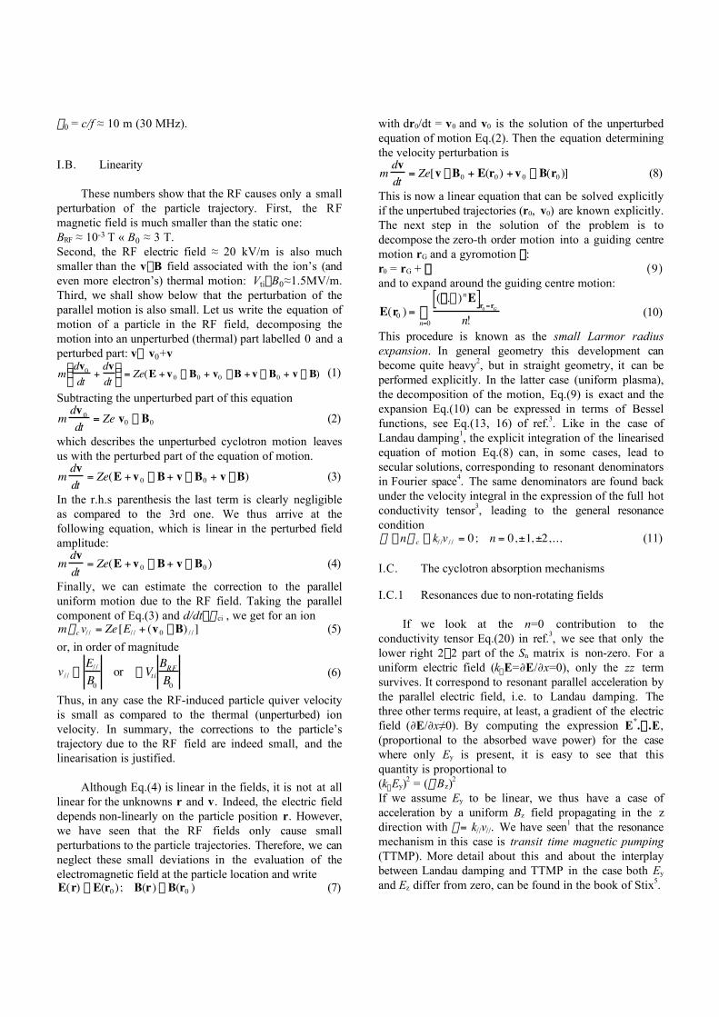
While it is easy to imagine how the fundamentalcyclotron resonance works, it is much harder to visualisethe reason why a particle rotating at the frequency w c canresonate with a wave that is rotating at twice thisfrequency! In order to understand how this happens it isuseful to come back first to the fundamental resonance andlook at the simpler situation where the wave propagates(or is non-uniform) in the x-direction while the E-field ispolarised in the y-direction. The principle is shown on topof Fig.1. The particle travels from left to right and at theinitial moment t=0, I assume that the electric force is inphase with the particle velocity. After a quarter period, ifthe field oscillates at the cyclotron frequency, w=wc, thefield is zero, after half a period it is negative, etc.Therefore, either the force is in phase with the particlemotion, or it is zero and over one cyclotron period, theparticle experiences a net acceleration in the direction ofits motion. If, with the same uniform field distribution,the field varies at twice the cyclotron frequency w=2wc,after a quarter period, it has changed sign, points in thenegative y direction and is perpendicular to the particle’svelocity. After half a cyclotron period, its phase has variedof 2p, it is again positive, points out of the paper in thedirection opposite to the particle’s velocity and so on.Hence, over a cyclotron period, the average force exerted
on the particle is zero, there is no net acceleration and noresonance. However, if the field varies linearly in space, asshown on the bottom of Fig.1, at the same time as italternates sign, the particle moves from one side of thegradient to the other, therefore keeping in phase with theelectric force and experiencing a net acceleration over oneperiod, as shown. It is therefore the interplay between thefield periodicity and the sampling of the field non-uniformity by the particle that allows resonance at thecyclotron harmonics.
I.C.3. Resonances due to the right-handed component ofthe field.
This type of resonance, corresponding to n<0, issomewhat counter-intuitive as the field rotates in thedirection opposite to the particle. However the resonancecondition shows that, in order to come into resonance, theparticle must have a very large velocity:
v / / =w + nwc
k/ />>Vti (13)
Fig. 1. Mechanism of the fundamental (top) and secondharmonic (bottom) resonance. The ion movesin the z-direction and the projection of itshelical motion on the (x,z) plane is shown:solid line, above the plane; dotted line, below.The electric field distribution along x is shownat quarter periods of the cyclotron frequency.The direction of the electric force F at theparticle’s position is also indicated.
One can then understand the resonance process asfollows. Let us start with a particle with zero parallelvelocity and a right-hand polarised field at frequency wslightly larger than w ci and positive phase velocityw/k/ />0. The particle sees the field rotating slightly fasterthan itself, in the opposite direction. Then if the particlestarts to move at a speed v// >0, in the reference framemoving at the same velocity, the field is now rotating atthe slightly lower frequency w’=w-k//v//. If v// is largeenough, this frequency may equal w ci but the ion and thefield are rotating in opposite directions. Then, if theparticle’s velocity becomes much larger, the field maybecome stationary w-k//v//=0: the particle is gyrating in astationary field. This cannot give rise to a resonance. If v//
is still increased, w-k//v//<0 and the wave field will start torotate in the left-handed direction. Still increasing theparticle’s velocity, we can come to the situation wherew-k//v//=-wci which means that the field is left-handpolarised and rotating at the cyclotron frequency, therebycausing resonant acceleration. This absorption mechanismis generally negligible for particles belonging to thethermal population in the plasma. However, for the muchfaster particles belonging to a high-energy tail, eithercreated by the RF itself, or by NBI or for a-particles, thismechanism may not be negligible at all. Even more so, aswe shall see, as the right-hand field component tends todominate in the fast wave, in the vicinity of resonances.
I.C.4. Quasilinear diffusion coefficient
Ion cyclotron heating tends to create high-energy tailsin the distribution function of the heated particles. Forheating at the n-th cyclotron harmonic, the diffusioncoefficient is of the form:
D µ Jn-1E+ + Jn+1E-
2ª Jn-1(
k^ v^
w c)
2
E+
2(13)
where E+ and E- are, respectively, the left-hand and right-hand components of the electric field:
E+ =12
(Ex + iEy ); E- =12
(Ex - iEy ) (14)
One notices the presence of a right hand componentcontribution in the diffusion coefficient. For not too fastparticles in the FW field, this contribution is negligiblebecause the argument of the Bessel functions is small.This is not necessarily the case for fast ions. In the case ofthe thermal population, one can take only the first term ofthe power series expansion of the Bessel functions, andwe get:• Fundamental: D µ K E+
2 with K a constant (15.1)
• Second harmonic: D µk^ v^
w c
2
E+
2(15.2)
• n-th harmonic: D µk^ v^
w c
2(n -1)
E+
2(15.3)
A first conclusion to be drawn from theseexpressions is that, as k^rL is a small quantity, thediffusion coefficient (hence the strength of the heating)strongly decreases with the harmonic number. Second,fundamental heating pushes all particles with the samestrength irrespective of their velocity: the diffusioncoefficient is independent of velocity. On the contrary,harmonic heating tends to accelerate more the fasterparticles. A consequence of this last observation is thatharmonic heating tends to create tails at higher energythan fundamental heating. In the same vein, harmonicheating tends to interact more with faster particles likebeams or alphas.
I.D. The FW dispersion and polarisation
The FW equation was given in section II.C of ref.1.We shall now specialise the expressions of the dielectrictensor components3 to the ICRF wherew ª w ci « wpi « wpe, w ce, (16)We obtain
S = 1 -w pe
2
w 2 - w ce2 -
w pi2
w 2 - w c i2 ª
i -
w pi2
w 2 - wc i2
i (17)
D =w ce
w
w pe2
w 2 - wce2 +
w c i
w
w pi2
w 2 - w c i2
iÂ
ªw pe
2
-wwce+
w c i
w
w pi2
w 2 - w c i2
i =
wwc i
w pi2
w 2 - w c i2
iÂ
(18)
The first line of Eq.(12) of ref.1 gives the relation linkingEx and Ey and can be used to compute the ratio of the left-to right-hand components of the electric field:Ex + iEy
Ex - iEy=
D + (S - N/ /2 )
D - (S - N/ /2 )
(19)
Let us now consider the case of a single ion species.Eqs.(17-18) become
S ª -w pi
2
w 2 - w c i2 ; D ª -
w c i
wS (20)
and
Ex + iEy
Ex - iEyª
1-w
w c i
- N/ /2 / S
1+w
w c i- N/ /
2 / Sª
w - w c i
w + w c i(21)
The last approximate equality follows from
N/ /2 / S ª
N/ /2 (wc i
2 - w 2 )w pi
2 < <1 (22)
The striking feature of the result Eq.(21) is that, atcyclotron resonance w=wci , in a plasma with only oneion species i, the left-hand polarised component of the
wave vanishes. Thus the cyclotron resonance mechanismcannot work because the resonant wave component isabsent! Incidentally, this shows explicitly why there is nosingularity of the fast wave propagation at the cyclotronfrequency3: the resonant wave component is blocked bythe resonance and all the power is transferred to the othercomponent. This dramatic result can be avoided byheating a small amount of ions of one species in a plasmawith ions of another species. This is called the minorityheating scenario. Consider, for example a plasma ofdeuterium with a minority of hydrogen. Then the wavepolarisation is determined by the majority componentwhile the wave frequency is the cyclotron frequency ofhydrogen. Inserting w=wcH=2wcD in Eq.(21) yieldsEx + iEy
Ex - iEyª
w - w cD
w + w cD=
2wcD - w cD
2wcD + w cD=
13
(23.1)
This is the most widely used minority heating scenario,denoted D-(H) to indicate that a minority of H is heated ina majority D plasma. This concept of heating a givenspecies in a mixture can be extended to other mixtures.For example in a reactor, one can heat D at thefundamental in a D-T mixture. Then, for not too large Dconcentration, the ratio of polarisations is:Ex + iEy
Ex - iEyª
w cD - w cT
w cD + w cT=
15
(23.2)
This explanation has the advantage of simplicity andto some extent gives a good picture of reality. The shrewdreader would however notice by working out himself thecomplete polarisation expression for a mixture of ions thateven in this case the left-handed polarisation vanishes ateach cyclotron harmonic! The final explanation can onlybe obtained by taking hot-plasma (absorption) effects3 intoconsideration and noting that in a mixture the wave left-handed component has a significant magnitude over amuch wider region around the cyclotron harmonic than inthe single-ion case. This is of course particularly evidentwhen only a small minority is considered. This allowsnon-collisional damping at Doppler-shifted frequencies toremain efficient over a much wider range as compared tothe single-ion case.
Another way to avoid the polarisation problem is towork at harmonics of the cyclotron frequency. ThenEx + iEy
Ex - iEyª
nwc i - w c i
nwc i + w c i=
n -1n +1
(23.3)
however, as we saw in Eq.(15.3), the damping strengthstrongly decreases with harmonic number.
I.E. The ion-ion hybrid resonance
Let us now consider, like in ref.3, the case of a 50%-50% mixture of D and T.
nD = nT = ne/2 (24)Then, taking into account the fact that w cD = w cH/2 andw cT = w cH/3, and definingw pH = 2w pD = 3w pT (25)we can recast the expressions for S and D, Eq.(17-18) as
S =2w pH
2
wcH2 - 4w 2 +
3w pH2
w cH2 - 9w 2 =
5wpH2 (wcH
2 - 6w 2 )(wcH
2 - 4w2 )(wcH2 - 9w 2 )
(25.1)
D =w
w cH
4wpH2
w cH2 - 4w2 +
9wpH2
w cH2 - 9w2
È
Î Í
˘
˚ ˙ (25.2)
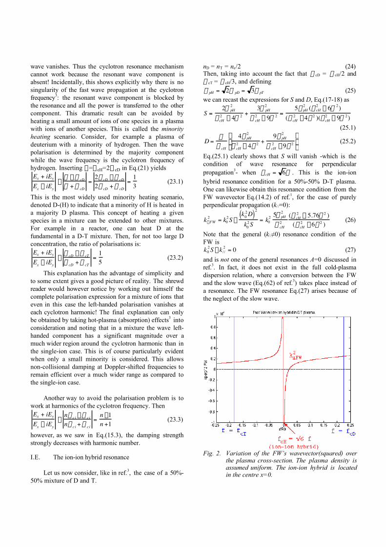
Eq.(25.1) clearly shows that S will vanish -which is thecondition of wave resonance for perpendicularpropagation3- when wcH = 6w . This is the ion-ionhybrid resonance condition for a 50%-50% D-T plasma.One can likewise obtain this resonance condition from theFW wavevector Eq.(14.2) of ref.1, for the case of purelyperpendicular propagation (k/ /=0):
k^FW2 = k0
2S -k0
2D( )2
k02S
= k02 5w pH
2
w cH2
(wcH2 - 5.76w 2 )
(wcH2 - 6w2 )
(26)
Note that the general (k/ /≠0) resonance condition of theFW isk0
2S - k / /2 = 0 (27)
and is not one of the general resonances A=0 discussed inref.3. In fact, it does not exist in the full cold-plasmadispersion relation, where a conversion between the FWand the slow wave (Eq.(62) of ref.3) takes place instead ofa resonance. The FW resonance Eq.(27) arises because ofthe neglect of the slow wave.
Fig. 2. Variation of the FW’s wavevector(squared) overthe plasma cross-section. The plasma density isassumed uniform. The ion-ion hybrid is locatedin the centre x=0.
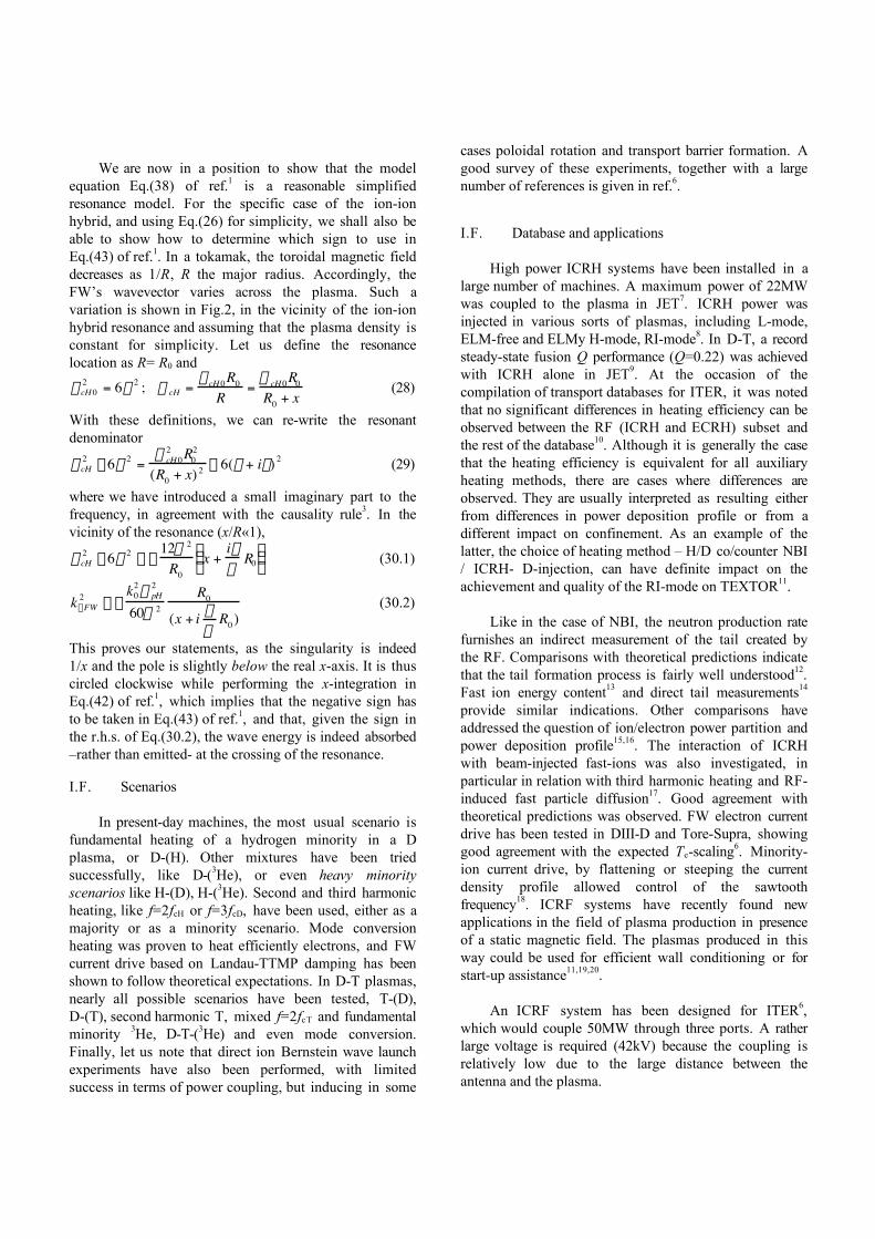
We are now in a position to show that the modelequation Eq.(38) of ref.1 is a reasonable simplifiedresonance model. For the specific case of the ion-ionhybrid, and using Eq.(26) for simplicity, we shall also beable to show how to determine which sign to use inEq.(43) of ref.1. In a tokamak, the toroidal magnetic fielddecreases as 1/R, R the major radius. Accordingly, theFW’s wavevector varies across the plasma. Such avariation is shown in Fig.2, in the vicinity of the ion-ionhybrid resonance and assuming that the plasma density isconstant for simplicity. Let us define the resonancelocation as R= R0 and
wcH 02 = 6w2 ; w cH =
wcH 0R0
R=
w cH 0R0
R0 + x(28)
With these definitions, we can re-write the resonantdenominator
wcH2 - 6w2 =
w cH 02 R0
2
(R0 + x) 2 - 6(w + in) 2 (29)
where we have introduced a small imaginary part to thefrequency, in agreement with the causality rule3. In thevicinity of the resonance (x/R«1),
wcH2 - 6w2 ª -
12w 2
R0x +
inw
R0Ê Ë Á ˆ
¯ ˜ (30.1)
k^FW2 ª -
k02w pH
2
60w 2R0
(x + i nw
R0 )(30.2)
This proves our statements, as the singularity is indeed1/x and the pole is slightly below the real x-axis. It is thuscircled clockwise while performing the x-integration inEq.(42) of ref.1, which implies that the negative sign hasto be taken in Eq.(43) of ref.1, and that, given the sign inthe r.h.s. of Eq.(30.2), the wave energy is indeed absorbed–rather than emitted- at the crossing of the resonance.
I.F. Scenarios
In present-day machines, the most usual scenario isfundamental heating of a hydrogen minority in a Dplasma, or D-(H). Other mixtures have been triedsuccessfully, like D-(3He), or even heavy minorityscenarios like H-(D), H-(3He). Second and third harmonicheating, like f=2fcH or f=3fcD, have been used, either as amajority or as a minority scenario. Mode conversionheating was proven to heat efficiently electrons, and FWcurrent drive based on Landau-TTMP damping has beenshown to follow theoretical expectations. In D-T plasmas,nearly all possible scenarios have been tested, T-(D),D-(T), second harmonic T, mixed f=2fcT and fundamentalminority 3He, D-T-(3He) and even mode conversion.Finally, let us note that direct ion Bernstein wave launchexperiments have also been performed, with limitedsuccess in terms of power coupling, but inducing in some
cases poloidal rotation and transport barrier formation. Agood survey of these experiments, together with a largenumber of references is given in ref.6.
I.F. Database and applications
High power ICRH systems have been installed in alarge number of machines. A maximum power of 22MWwas coupled to the plasma in JET7. ICRH power wasinjected in various sorts of plasmas, including L-mode,ELM-free and ELMy H-mode, RI-mode8. In D-T, a recordsteady-state fusion Q performance (Q=0.22) was achievedwith ICRH alone in JET9. At the occasion of thecompilation of transport databases for ITER, it was notedthat no significant differences in heating efficiency can beobserved between the RF (ICRH and ECRH) subset andthe rest of the database10. Although it is generally the casethat the heating efficiency is equivalent for all auxiliaryheating methods, there are cases where differences areobserved. They are usually interpreted as resulting eitherfrom differences in power deposition profile or from adifferent impact on confinement. As an example of thelatter, the choice of heating method – H/D co/counter NBI/ ICRH- D-injection, can have definite impact on theachievement and quality of the RI-mode on TEXTOR11.
Like in the case of NBI, the neutron production ratefurnishes an indirect measurement of the tail created bythe RF. Comparisons with theoretical predictions indicatethat the tail formation process is fairly well understood12.Fast ion energy content13 and direct tail measurements14
provide similar indications. Other comparisons haveaddressed the question of ion/electron power partition andpower deposition profile15,16. The interaction of ICRHwith beam-injected fast-ions was also investigated, inparticular in relation with third harmonic heating and RF-induced fast particle diffusion17. Good agreement withtheoretical predictions was observed. FW electron currentdrive has been tested in DIII-D and Tore-Supra, showinggood agreement with the expected Te-scaling6. Minority-ion current drive, by flattening or steeping the currentdensity profile allowed control of the sawtoothfrequency18. ICRF systems have recently found newapplications in the field of plasma production in presenceof a static magnetic field. The plasmas produced in thisway could be used for efficient wall conditioning or forstart-up assistance11,19,20.
An ICRF system has been designed for ITER6,which would couple 50MW through three ports. A ratherlarge voltage is required (42kV) because the coupling isrelatively low due to the large distance between theantenna and the plasma.
II. LOWER HYBRID HEATING
In the lower hybrid (LH) heating domain, two wavescoexist: the fast and the slow wave. For N// =0, they areuncoupled and evanescent and only the FW exhibits aresonance at the LH. If N// is increased (up to N// ≈1), bothwaves become propagating at the edge but merge somedistance inside the plasma (confluence). Further in, bothare evanescent (complex conjugate k^
2 ) and the central partof the plasma is not accessible to the waves from theedge. It is only when the accessibility condition Eq.(65)of ref.3, is satisfied that the two waves uncouple andpropagate both inside the plasma. The accessibilitycondition implies that the launcher must be designed suchas to launch waves with a parallel wavelength shorter thanl / / = c /(Nc f ) (31)
This is obtained by using an array of phased waveguidescalled the grill2 1.
The original concept of LH heating is to launch theslow wave (SW) at a frequency below the central value ofthe LH resonance. The SW then propagates up to the LHresonance and is absorbed there. It however becameapparent from experiments that usually the wave tended tobe absorbed by electron Landau damping before havingreached the resonance. This is largely due to the conepropagation effect3. Indeed, the wave rays tend align to themagnetic field as the wave propagates inwards, eventuallybecoming exactly parallel at the LH resonance.Accordingly, the waves tend to circle around the plasmacentre and to damp there. This efficient electronabsorption is now exploited and recent LH heatingexperiments operate at frequencies above the central LHfrequency, so that there is no longer a wave resonanceinside the plasma and all the power goes to electrons.With an asymmetric N// spectrum, LH heating is used as acurrent drive method. The cone behaviour is responsiblefor the main problem in applying LH to reactor-sizemachines, namely that the LH wave energy tends topropagate peripherally around the plasma and to depositits energy away from the plasma centre. More preciseinformation about the location where the power isdeposited in toroidal geometry can be obtained using ray-tracing techniques2 2.
LH was first used as a heating method. Thecorresponding experimental results have been nicelysummarised in a plot showing the different heatingregimes in FT2 3. At low density, LH waves heatelectrons. As the density is increased, electron heatingfades away and ion heating sets in, creating ion tails. Atstill higher density, ion heating also decreases and
disappears while parametric decay activity sets in. Thedifferent damping mechanisms of LH waves and theinterpretation problems of experimental results, such asthe spectral gap problem, are described in the book byCairns2 4. Presently, the main application of LH is non-inductive current drive; it constitutes today the best,experimentally proven, current drive method. In large hotplasmas like ITER or reactors, the LH waves can usuallynot reach the centre. Accordingly, LH in ITER2 5 ismainly seen as a tool for controlling the current profile byoff-axis current drive in advanced scenarios2 6. It can alsobe used for saving volt-seconds in the ramp-up phase ofthe plasma current.
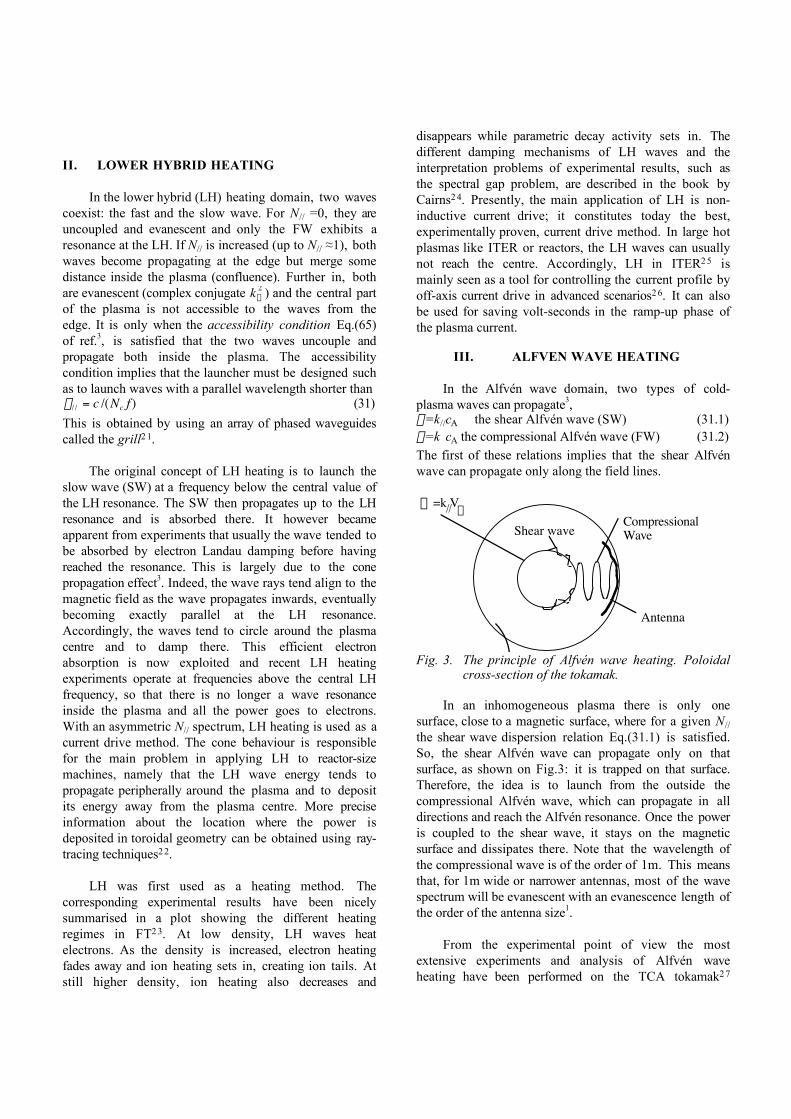
III. ALFVEN WAVE HEATING
In the Alfvén wave domain, two types of cold-plasma waves can propagate3,w=k//cA the shear Alfvén wave (SW) (31.1)w=k cA the compressional Alfvén wave (FW) (31.2)The first of these relations implies that the shear Alfvénwave can propagate only along the field lines.
CompressionalWave
Antenna
Shear wave
=k Vw // A
Fig. 3. The principle of Alfvén wave heating. Poloidalcross-section of the tokamak.
In an inhomogeneous plasma there is only onesurface, close to a magnetic surface, where for a given N//
the shear wave dispersion relation Eq.(31.1) is satisfied.So, the shear Alfvén wave can propagate only on thatsurface, as shown on Fig.3: it is trapped on that surface.Therefore, the idea is to launch from the outside thecompressional Alfvén wave, which can propagate in alldirections and reach the Alfvén resonance. Once the poweris coupled to the shear wave, it stays on the magneticsurface and dissipates there. Note that the wavelength ofthe compressional wave is of the order of 1m. This meansthat, for 1m wide or narrower antennas, most of the wavespectrum will be evanescent with an evanescence length ofthe order of the antenna size1.
From the experimental point of view the mostextensive experiments and analysis of Alfvén waveheating have been performed on the TCA tokamak2 7

(R0=0.6m). Although antenna coupling and general wavebehaviour appeared to be in agreement with the theory,generally speaking little plasma heating was observedwhile the main effect of the RF was a large densityincrease, sometimes interpreted as an increase in theparticle confinement time. In view of these disappointingresults there have been few attempts to apply Alfvén waveheating to large tokamaks and this method is usually notmentioned for the heating of ITER or reactors. However,there has been some renewed interest in this field as theconversion to the kinetic Alfvén wave may inducepoloidal shear flows, and possibly generate transportbarriers28.
IV. FURTHER READING
An excellent introductory overview of the differentwave heating methods is given by Cairns2 4. A verycomplete work on plasma waves is that of Stix5.Brambilla29 reviews the same subject with finer detail anda more direct view toward practical applications. Inparticular, many dispersion relation features are discussedin detail.
REFERENCES1. R. KOCH, “The coupling of electromagnetic power to
plasmas” These Proc.2. P. LAMALLE, “Kinetic theory of plasma waves: Part III
Inhomogeneous plasma” These Proc.3. E. WESTERHOF, “Kinetic theory of plasma waves: Part II
Homogeneous plasma” These Proc.4. R. KOCH, “Heating by Waves in the Ion Cyclotron
Frequency Range”, Transactions of Fusion Technology,33, 227, (1998)
5. T.H. STIX,”Waves in plasmas”, AIP New York (1992).6. ITER team, et al., “ITER Physics basis”, to be published
in Nucl. Fus. (1999 or 2000)7. V.P.BHATNAGAR, et al., “ICRF Heating and Synergistic
LH and Fast-Wave current Drive in JET”, 9th Top. Conf.on Radio Freq. Power in Plasmas, Charleston 115,(1991)
8. J.P.H.E. ONGENA, “Extrapolation to reactors”, TheseProc
9. J. JACQUINOT & The JET Team, “Deuterium-tritiumoperation in magnetic confinement experiment: resultsand underlying physics”, Plasma Phys. Contr. Fus. 41,A13,(1999)
10. K. THOMSEN, et al., “ITER H-mode confinementdatabase update”, Nucl. Fus. 34, 131, (1994).
11. R. KOCH, et al., “Progress on TEXTOR-94: Radiative-Improved-Mode and Radio-Frequency plasmaproduction in the Ion Cyclotron Range”, Proc. VIUkrainian Conf. and School on Plasma Phys. and Contr.Fus., Alushta 1, 70,(1998)
12. L.-G. ERIKSSON, et al., “Theoretical analysis of ICRFheating in JET DT plasmas”, ICPP & 25th EPS Conf. onContr. Fus. and Plasma Phys., Prague, Europhysics Conf.Abstracts 22C, 1186, (1998)
13. L.-G. ERIKSSON, et al., “Comparison of Time DependentSimulations with Experiments in Ion Cyclotron HeatedPlasmas”, Nucl. Fus., 33, 1037, (1993)
14. D.F.H. START, et al., “ICRF Results in D-T Plasmas inJET and TFTR and Implications for ITER”, Plasma Phys.Contr. Fus., 40, A87, (1998)
15. R. KOCH et al., “A Comparison Between ICRF Theoryand Experiment”, Plasma Phys. Contr. Fus., 30, 1559,(1988).
16. M.PORKOLAB, et al., “Recent Progress in ICRFPhysics”, Plasma Phys. Contr. Fus., 40, A35,(1998)
17. R. KOCH et al., “Interaction of ICRF Waves with FastParticles on TEXTOR”, Plasma Phys. Contr. Fus., 37,A291, (1995).
18. V.P.BHATNAGAR, et al., “Local Magnetic Shear Controlin a Tokamak via Fast Wave Minority Ion Current Drive:Theory and Experiments in JET”, Nucl. Fus., 34, 1579,(1994)
19. R. KOCH et al., “Low loop voltage start-up of theTEXTOR-94 plasma with ICRF and/or NBI assistance”,26th EPS Conf. on Contr. Fus. & Plasma Phys.,Maastricht, (1999)
20. A. LYSSOIVAN et al., “ICRF Plasma Production in TORESUPRA: Analysis of Antenna Coupling and PlasmaProperties”, ibid.
21. A. EKEDAHL, et al., “Conditioning and high poweroperation of the lower hybrid current drive launcher inJET” Report JET- P(97)19 (1997)
22. M. BRAMBILLA, ”Ray tracing of lower hybrid and ioncyclotron waves”, Computer Phys. Reports 4, 71 (1986).
23. F. ALLADIO et al., ”Lower hybrid heating experimentson FT”, 4th Symp. Heating in Toroidal Plasmas, Int.School of Plasma Phys. (Varenna) 1, 546 (1984).
24. R.A. CAIRNS, ”Radiofrequency heating of plasmas”,Adam Hilger, IOP (1991).
25. P. FROISSARD, et al., “Lower hybrid wave injectionsystem”, NET report EUR FU/XII-218/113/98 (1998)
26. D. MOREAU et al., “ITER operation scenarios involvingcurrent profile control”, NET report EUR FU/XII-218/112/98 (1998)
27. G. BESSON et al., ”A review of Alfvén waves heating”,Plasma Phys Contr. Fus. 28, 1291 (1986).
28. G. AMARANTE SECUNDO, et al., ” Calculation of Alfvénwave driving forces, plasma flow, and current drive inthe TCABR tokamak”, 26th EPS Conf. on Contr. Fus.Plasma Phys., Maastricht, (1999)P3.092
29. M. BRAMBILLA, “Kinetic Theory of Plasma Waves –Homogeneous Plasmas”, Clarendon Press Oxford(1998).