the history of system safety - home - ukfsc material/system safety... · system safety handbook ......
TRANSCRIPT
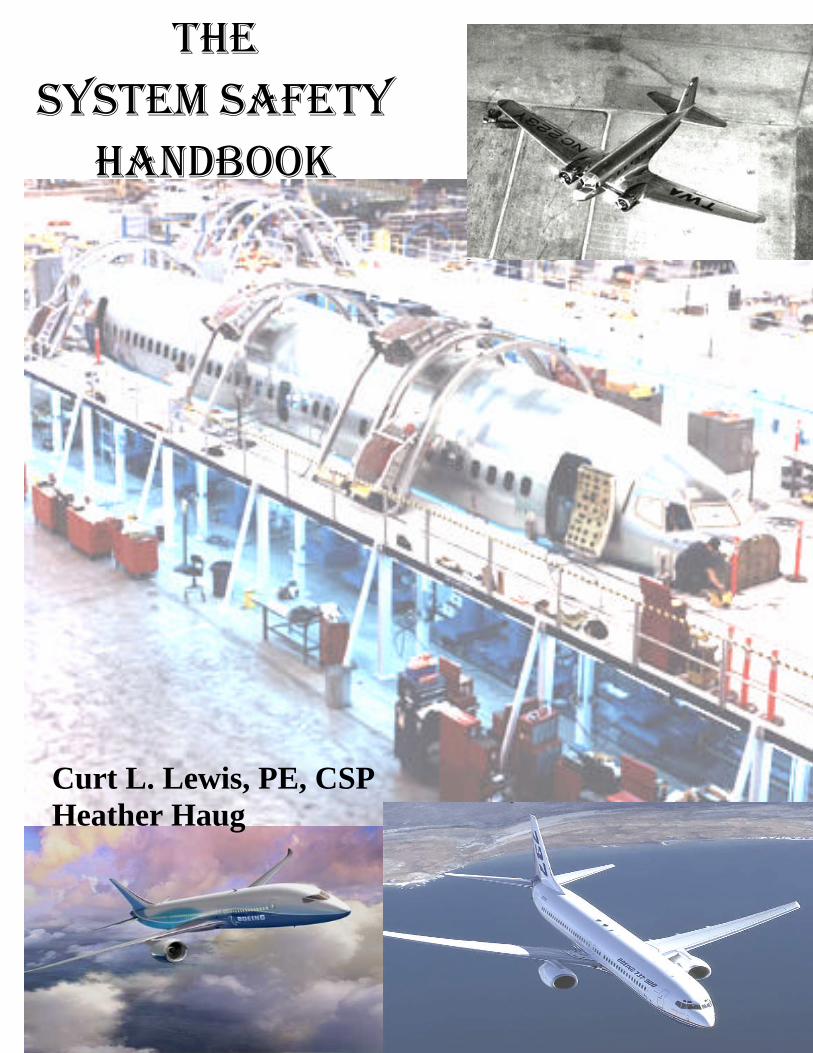
THE SYSTEM SAFETY
HANDBOOK
Curt L. Lewis, PE, CSP Heather Haug
1
As a simple guide to System Safety, one should not expect to have a complete
knowledge or understanding of such a complex topic. It is the guide’s duty to only
enlighten the reader’s knowledge and make them aware of some very important
topics related to system safety. It is impossible to fully encompass the total
amount of information needed to become a safety professional just with in a
simple system safety guide. Therefore, please note that in reading the following
guide, your horizons will become enhanced and broadened, but you will not
become an expert over night.
“As we approach the twenty-first century, many challenges face the safety, engineering,and management communities. Risks and the potential for catastrophic loss aredramatically increasing as technology advances at an ever-increasing rate. The publicdemands a high level of safety in products and services, yet, in the face of worldcompetition, the safety effort must be timely and cost-effective” (System Safety, 1999pg.xiii)
2
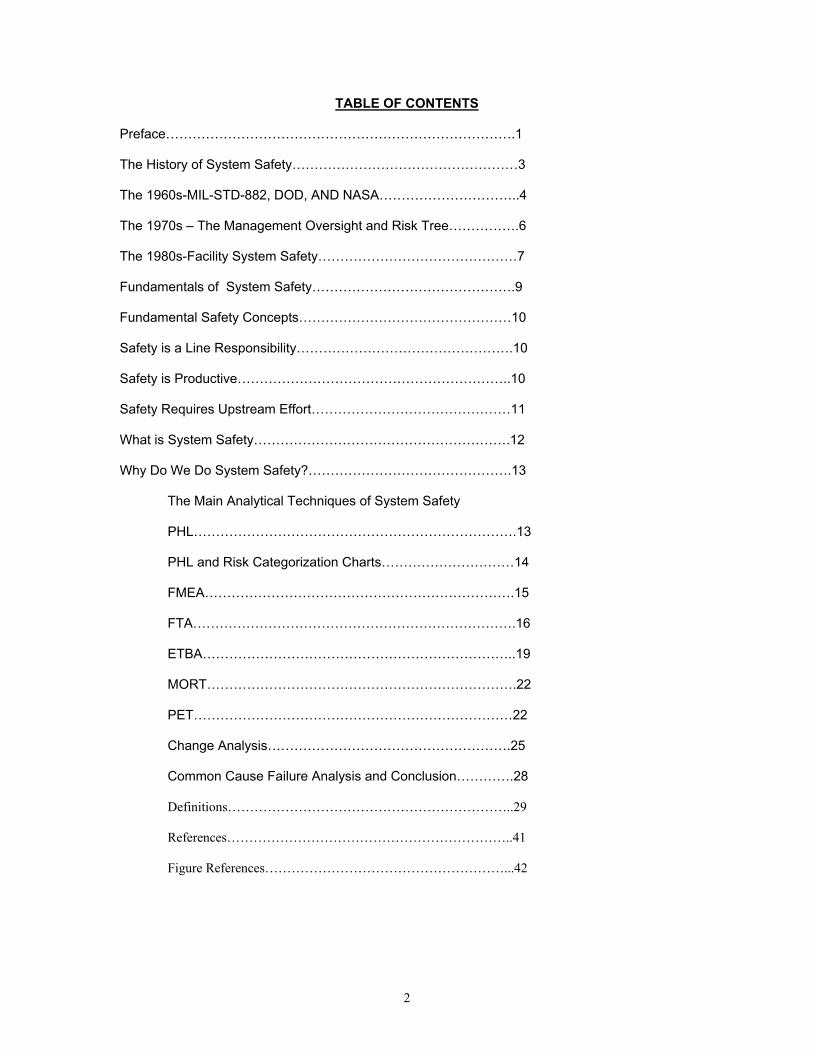
TABLE OF CONTENTS
Preface…………………………………………………………………….1
The History of System Safety……………………………………………3
The 1960s-MIL-STD-882, DOD, AND NASA…………………………..4
The 1970s – The Management Oversight and Risk Tree…………….6
The 1980s-Facility System Safety………………………………………7
Fundamentals of System Safety……………………………………….9
Fundamental Safety Concepts…………………………………………10
Safety is a Line Responsibility………………………………………….10
Safety is Productive……………………………………………………..10
Safety Requires Upstream Effort………………………………………11
What is System Safety………………………………………………….12
Why Do We Do System Safety?……………………………………….13
The Main Analytical Techniques of System Safety
PHL……………………………………………………………….13
PHL and Risk Categorization Charts…………………………14
FMEA…………………………………………………………….15
FTA……………………………………………………………….16
ETBA……………………………………………………………..19
MORT…………………………………………………………….22
PET………………………………………………………………22
Change Analysis……………………………………………….25
Common Cause Failure Analysis and Conclusion………….28
Definitions………………………………………………………..29
References………………………………………………………..41
Figure References………………………………………………...42
3
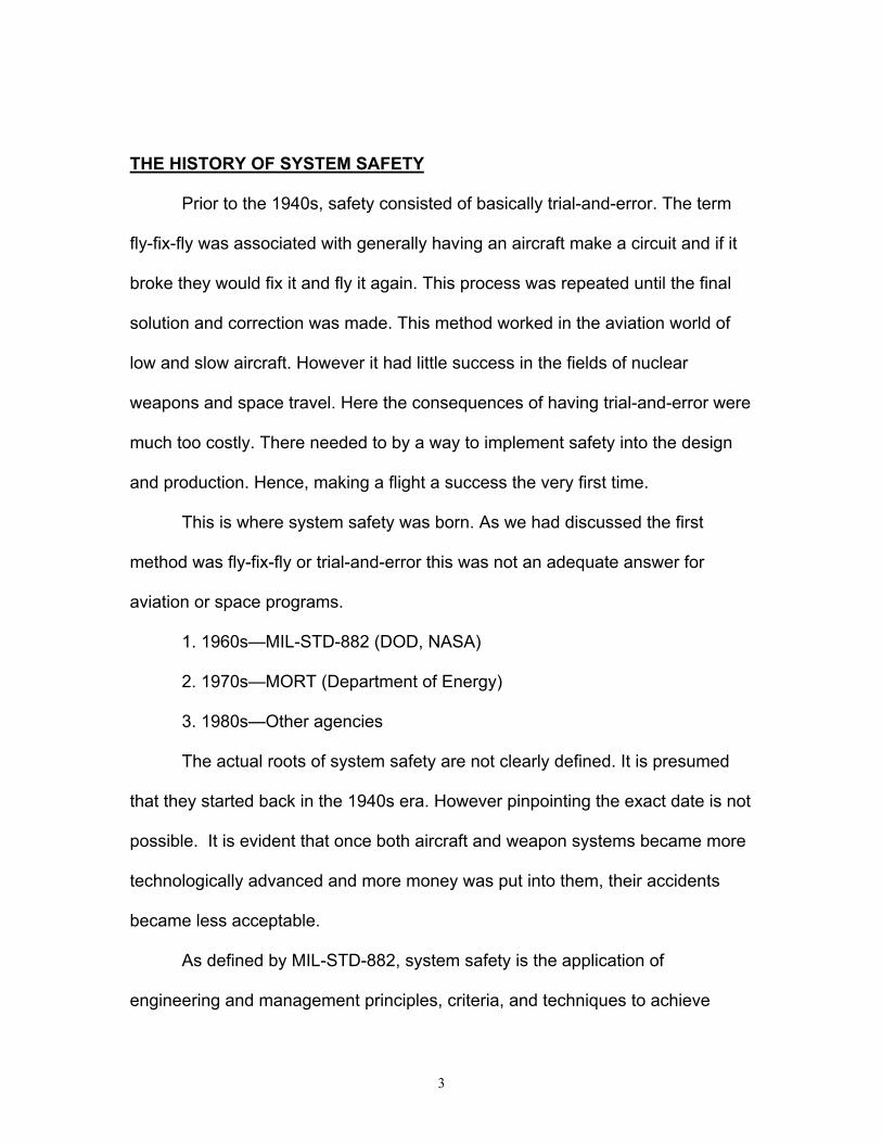
THE HISTORY OF SYSTEM SAFETY
Prior to the 1940s, safety consisted of basically trial-and-error. The term
fly-fix-fly was associated with generally having an aircraft make a circuit and if it
broke they would fix it and fly it again. This process was repeated until the final
solution and correction was made. This method worked in the aviation world of
low and slow aircraft. However it had little success in the fields of nuclear
weapons and space travel. Here the consequences of having trial-and-error were
much too costly. There needed to by a way to implement safety into the design
and production. Hence, making a flight a success the very first time.
This is where system safety was born. As we had discussed the first
method was fly-fix-fly or trial-and-error this was not an adequate answer for
aviation or space programs.
1. 1960s—MIL-STD-882 (DOD, NASA)
2. 1970s—MORT (Department of Energy)
3. 1980s—Other agencies
The actual roots of system safety are not clearly defined. It is presumed
that they started back in the 1940s era. However pinpointing the exact date is not
possible. It is evident that once both aircraft and weapon systems became more
technologically advanced and more money was put into them, their accidents
became less acceptable.
As defined by MIL-STD-882, system safety is the application of
engineering and management principles, criteria, and techniques to achieve
4
acceptable mishap risk, within the constraints of operation, effectiveness and
suitability, time and cost, throughout all phases of the system life cycles. Today,
system safety is pushing at the constrains of its MIL-STD definitions. To
accurately define system safety, one must first determine the scope of the
system in question. Is it composed of only one element (e.g., hardware or
software), or will the system include the human factor as it applies to the design,
operation, handling or maintenance of the system or its parts? It many be simple
device, or it could be a complicated series of devices and/or sysbsystems all
functioning together in a specific environment. Defining what comprises the
system is an essential first step in determining its system safety.
THE 1960s—MIL-STD-882, DOD, AND NASA
In the 1960s system safety began to take on its own role. It became an
issue that needed to be addressed.
1. USAF publishes “System Safety Engineering for the Development of Air
Force Ballistic Missiles” (1962)
2. USAF publishes MIL-S-38130, “General Requirements for Safety
Engineering of Systems and Associated Subsystems and Equipment”
(1963)
3. System Safety Society founded (1963)
4. DOD adopts MIL-S-38130 as MIL-S-381308A (1966)
5. MIL-S-381308A revised and designated MIL-STD-882B, “System
Safety Program Requirements” (1969) (Stephenson, 2000, p. 4).

5
Most people would agree that one of the first major formal system safety efforts
involved the Minuteman Intercontinental Ballistic Missile (ICBM) program. This is
a series of pre-Minuteman design-related silo accidents, which probably provided
at least part of the incentive (U.S. Air Force 1987).
The U.S. Air Force Ballistic System Divisions were the ones who
generated the early system safety requirements. Early air force documents
provided the basis for MIL-STD-882 (July 1969), “System Safety Program for
Systems and Associated Subsystems and Equipment: Requirements for.” This
particular document (and revisions MIL-STD-882 and MIL-STD-882B) became,
and still remain, the bible for the Department of Defense (DOD) system safety
effort (Moriarty and Roland 1983).
Other early system safety efforts were associated with the aerospace
industry, including civil and military aviation and the space program. Here the
weapon systems were also a part in this.
The National Aeronautical and Space Administration (NASA) developed
its own system safety program requirements. The development of this program
closely paralleled the MIL-STD-882 approach given by the DOD. Reasons for
these two agencies to use a similar process is because the two tend to share
contractors, personnel, and, missions.
In the early to mid-1960s, Roger Lockwood in Los Angeles founded the
System Safety Society. The society later became known as the Aerospace
System Safety Society in California in 1964. The name was changed to System
6
Safety Society in 1967 (Medford 1973). In 1973, the System Safety Society was
incorporated as “an international, non-profit, organization dedicated to the safety
of systems, products, and services (System Safety Society 1989).
THE 1970s – THE MANAGEMENT OVERSIGHT AND RISK TREE
In the later part of 1960, the Atomic Energy Commission (AEC) made the
decision to hire William G. Johnson, a retired manager of the National Safety
Council, to develop a system safety program for the AEC. This decision was
made due to the awareness of the system safety efforts in the DOD and NASA
communities.
The AEC programs and AEC contractors had good (some better than
others) safety programs in place, the programs and approaches varied widely.
This lack of standardization or commonality made effective evaluation,
monitoring, and control of safety efforts throughout the organization difficult, if not
impossible.
Here the goals became to improve the overall safety effort by:
1. Develop a new approach to system safety that incorporated the best features
of existing system safety efforts.
2. Provide a common approach to system safety and safety management to be
used throughout the AEC and by their contractors
A risk tree (MORT) manual and revised management oversight was published by
the AEC in 1973. William G. Johnson mired his MORT program heavily off of the
7
existing DOD and NASA programs. However it bored little resemblance to the
MIL-STD-882.
In the 1970s Bill Johnson expanded and supplemented the System Safety
Development Center. (SSDC) in Idaho Falls, Idaho. The MORT program
provides the direction for this second major branch of the system safety effort.
Progress in the 1970s included:
1. NASA publishes NHB 1700.1 (V3), “System Safety” (1970)
2. AEC publishes “MORT – The Management Oversight and Risk
Tree” (1973)
3. System Safety Development Center founded (1974)
4. MORT training initiated for AEC, ERDA, and DOE (1975)
5. MIL-STD-882A replaces MIL-STD-882 (1977) (Stephenson,
2000, p. 6).
THE 1980’S – FACILITY SYSTEM SAFETY
Three factors throughout the 1980s have driven system safety tools and
techniques in other than the traditional aerospace, weapons, and nuclear fields.
First, a more sophisticated upstream safety approach was the product of
highly complex and costly non-flight, and non-nuclear projects. Second, added
incentives to produce safe products had introduced product liability litigation.
Third, the upstream safety efforts lead to better design because of system safety
experiences that have demonstrated positive progress.
8
Significant programs initiated or developed in the 1980’s include the
facility system safety efforts of the Naval Facilities Command and the U.S. Army
Corps of Engineers and initiatives in the petrochemical industry.
1. MIL-STD-882B replaces MIL-STD 882A (1984)
2. NAVFAC sponsors system safety courses (1984)
3. AIChE publishes “Guidelines for Hazard Evaluations Procedures”
(HazOps) (1985)
4. MIL-STD-882B updated by Notice 1(1987)
5. USACE-sponsored facility system safety workshops initiated (1988)
(Stephenson, 2000, p. 6).
The constant need for a system safety effort for major military construction
projects resulted in the development of draft guidelines and facility systems
safety workshops for the military safety and engineering communities. “By the
end of the decade, facility system safety training programs for government
employees were established, and similar courses for contractors were available.
Regulations outlining facility system safety efforts were pending and facility
system safety efforts were being required on selected military contraction
projects. In additions, NASA was initiating facility systems safety efforts,
especially for new space station support facilities (Stephenson, 2000, p. 6).
In 1985, the American Institute of Chemical Engineers (AIChE) initiated a
project to produce the “Guidelines for Hazard Evaluation Procedures.” This
document, prepared by Battelle, includes many system safety analysis tools.
Even though frequently identified as hazard and operability (HazOp) programs,
9
the methods being developed by the petrochemical industry to use preliminary
hazard analyses, fault trees, failure modes, effects, and criticality analyses, as
well as similar techniques to identify, analyze, and control risks systematically,
look very much like system safety efforts tailored for the petrochemical industry
(Goldwaite 1985) (Stephenson, 2000, p. 6-7).
FUNDAMENTALS OF SYSTEM SAFETY
Lack of standardization or commonality was one of the major problems
confronting the systems safety community. Having “universally accepted”
definitions to even basic terms would be a good place to start, however these
basic terms do not exist as of yet. Some of the terms that are provided are
defined in non-technical language to ensure the reader understands each term
as used in this article.
Safety: Freedom from harm. Safety is achieved by doing things right the
first time, every time
System: A composite of people, procedures, and plant and hardware
working within a given environment to perform a given task
System Safety: The discipline that uses systematic engineering and
management techniques to aid in making systems safe throughout their
life cycles
Hazard: Something that can cause significant harm
Risk: The chance of harm, in terms of severity and probability
10
Safety Community: That group of individuals who provide staff support to
the line organization in support of the safety effort. It includes occupational
and industrial safety, system safety, industrial hygiene, health,
occupational medicine, environmental safety, fire protection, reliability,
maintainability, and quality assurance personnel. (Stephenson, 2000, p. 8-
FUNDAMENTAL SAFETY CONCEPTS
Five fundamental safety concepts apply to any safety effort.
1. Safety is a line responsibility
2. Safety is productive
3. Safety requires upstream effort
4. Safety depends on the safety precedence sequence
5. Systematic tools and techniques help (Stephenson, 2000, p. 9).
SAFETY IS A LINE RESPONSIBILITY
There is an old principle within safety. It is line managers and supervisors
are responsible for the safety of their organizational units and operations. This
fundamental must be understood and accepted company wide. The safety
professional’s job is to provide the staff support necessary to ensure that the line
organization is able to do its job well and effectively.
11
SAFETY IS PRODUCTIVE
Safety is achieved by doing things right the first time, and from there on
out every time. Not only is this the goal that everyone should strive for, you will
want to have a safe, extremely efficient, productive, and cost-effective operation.
SAFETY RERQUIRES UPSTREAM EFFORT
The selection, initial training, development of the procedures, and the
design of the facilities and equipment are the types of tasks that ultimately
determine the safety of the workplace. However in order to ensure that these
listed items are carried out effectively the “good safety practices” must begin at
the top or as far upstream as possible. The good news about fostering a healthy
and safe workplace is that if improvements are needed they can often be made
for a minimal amount of money if they are caught far enough upstream.
Safety depends on the safety precedence sequence. This is a prioritized
list of controls that should be considered and applied, in sequence, to eliminate
or control identified hazards:
1. Design for minimum hazard (the first and most effective way to control
identified hazards is to eliminate them through design or engineering
changes)
2. Provide safety devices (use physical guards or barriers to separate
potential unwanted energy flows or other hazards from potential
targets)
12
3. Provide warning devices (These should be applied to any remaining
hazards)
4. Control with procedures and training (this should be a last resort to
accepting the remaining residual hazards)
5. Accept remaining residual hazards (even after all of the above
changes have been implemented there will be some left over hazards)
(Stephenson, 2000, p. 11).
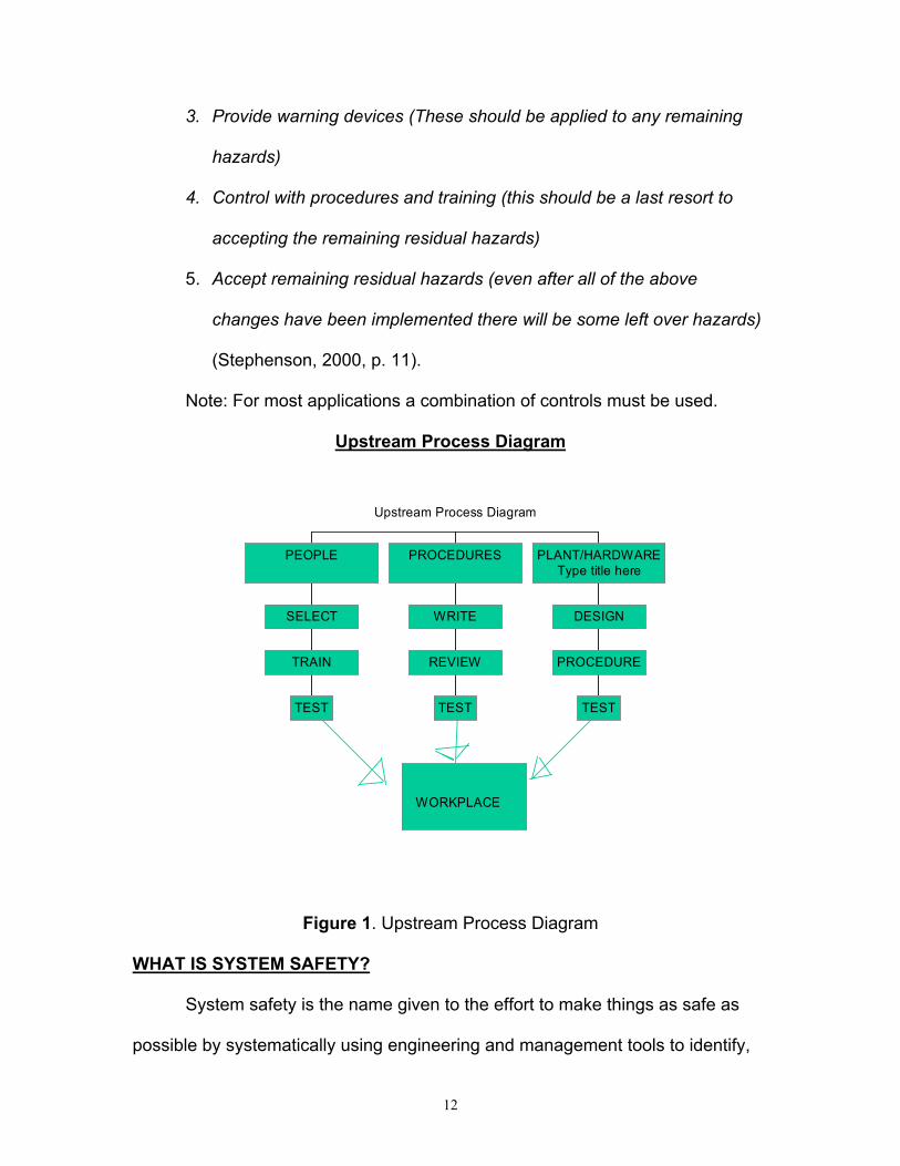
Note: For most applications a combination of controls must be used.
Upstream Process Diagram
Figure 1. Upstream Process Diagram
WHAT IS SYSTEM SAFETY?
System safety is the name given to the effort to make things as safe as
possible by systematically using engineering and management tools to identify,
Upstream Process Diagram
WORKPLACE
TEST
TRAIN
SELECT
PEOPLE
TEST
REVIEW
WRITE
PROCEDURES
TEST
PROCEDURE
DESIGN
PLANT/HARDWAREType title here

13
analyze, and control hazards. The system safety “effort” is sometimes called an
approach, a discipline, a concept, a doctrine, and/or a philosophy.
WHY DO WE DO SYSTEM SAFETY?
The main reason that we practice and try to implement system safety is to
achieve better safety. So you may ask how do we achieve better safety? This is
done by complying with the appropriate codes, standards, and regulations that
are, by at large, political documents.
Unfortunately safety is a reactive program usually. When in reality it
should be a pro-active operation. It is said that safety is “written in blood” this is
referring to the fact that for the most part the only time those operations or
procedures will be changed is if some one sheds blood.
Here are a few analysis that have been created to help figure out why we
do system safety.
THE MAIN ANALYTICAL TEQUINIUES OF SYSTEM SAFETY
PHL
The PHL (preliminary hazard list) it is an initial look at the entire system. If
a PHL is available we are able to expand it by adding new hazards that may be
identified as more project information is developed or available. If a PHL has not
already been prepared, we can use what is called a PHA. This serves as the
primary hazard identification tool as well as the starting point for the PHL. The
PHA simple expands the PHL by identifying additional hazards, analyzing
14
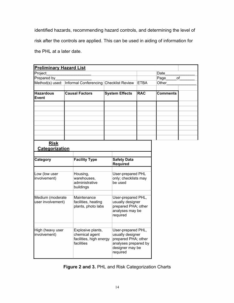
identified hazards, recommending hazard controls, and determining the level of
risk after the controls are applied. This can be used in aiding of information for
the PHL at a later date.
Preliminary Hazard ListProject_____________________ Date______________Prepared by_________________ Page_____of_______Method(s) used: Informal Conferencing Checklist Review ETBA Other______________
HazardousEvent
Causal Factors System Effects RAC Comments
RiskCategorization
Category Facility Type Safety DataRequired
Low (low userinvolvement)
Housing,warehouses,administrativebuildings
User-prepared PHLonly; checklists maybe used
Medium (moderateuser involvement)
Maintenancefacilities, heatingplants, photo labs
User-prepared PHL,usually designerprepared PHA; otheranalyses may berequired
High (heavy userinvolvement)
Explosive plants,chemical agentfacilities, high energyfacilities
User-prepared PHL,usually designerprepared PHA; otheranalyses prepared bydesigner may berequired
Figure 2 and 3. PHL and Risk Categorization Charts
15
FMEA
FMEA, also known as Failure Modes and Effect Analysis is most
commonly used for system and subsystem hazard analyses. FMEA was
originally a tool created by SAE reliability engineers. This process analyzes
potential effects caused by system elements ceasing to behave as intended.
FMEA can not be done until the design process has proceeded to the point that
the system elements have been selected at the level that the analysis is to
explore.
Typically, FMEA is done in conjunction with or soon after the PHA.
However it can be done anytime during the systems lifetime. Some principle
limitations associated with FMEA are that there is a tendency to have human
errors, and hostile environments are frequently overlooked. Sometimes faults of
the system and effects of coexisting failures are not considered. If the system is
complex enough the process can be tedious and time consuming as well.
Many times FMEA is done simply to satisfy the urge to need to “Do
Safety”. However there are some benefits of using FMEA. The benefits include
being able to discover potential single-point failures, and assesses risk for
potential single-element failures.
Definitions associated with FMEA are:
Fault: The inability to function in a desired manner, or operates in
an undesired manner, regardless of cause.
Failure: A fault due to breakage, wear out, compromise structural
integrity, etc.
16
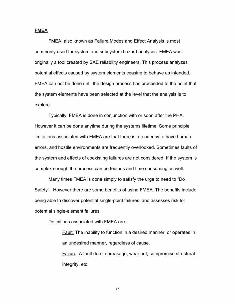
Failure Mode: The mode in which a fault occurs
So you may ask what is the use in knowing all this stuff about FMEA?
This will help you:
1. Optimize reliability
2. Guide design evaluation and improvement
3. Guide design of system to “fail safe” or crash softly
4. Guide design of system to operate satisfactorily using
equipment of “low” reliability
5. Guide component/manufacturer selection
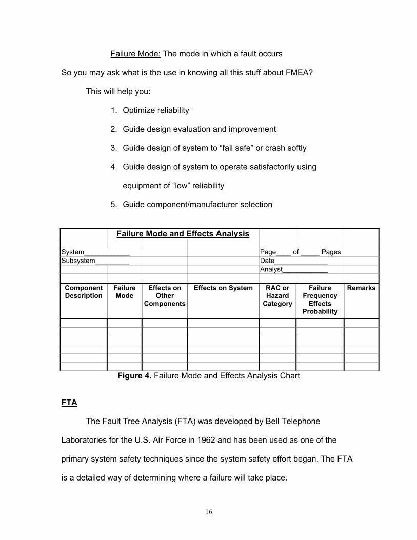
Failure Mode and Effects Analysis
System____________ Page____ of _____ PagesSubsystem_________ Date______________
Analyst____________
ComponentDescription
FailureMode
Effects onOther
Components
Effects on System RAC orHazard
Category
FailureFrequency
EffectsProbability
Remarks
Figure 4. Failure Mode and Effects Analysis Chart
FTA
The Fault Tree Analysis (FTA) was developed by Bell Telephone
Laboratories for the U.S. Air Force in 1962 and has been used as one of the
primary system safety techniques since the system safety effort began. The FTA
is a detailed way of determining where a failure will take place.
17
There are two different ways to look at the FTA. The first approach is the
qualitative approach. The seconded way is by the quantitative approach. The
FTA is considered one of the most reliable and meaningful system safety
techniques used and available when we are looking at reducing an undesired
event. The negative aspect of this technique is that it is a bit more pricey
because it requires a skilled annalist and a large amount of time. The benefits of
using this system however is that it provides quality data and can make the
system being tested more reliable once the analysis is complete.
The purpose of FTA is to find where the failure will occur and fix it before if
happens. You could say that using the FTA analysis is a preventative measure.
Major input requirements for the FTA is the main event. In order to chose this
“main event’ you must have data and history to back up your decision to test the
problem at hand. A helpful tool in choosing what you want to do the FTA on is by
looking at past hazard analysis if there are available. Lets look at the general
approach to get started.
1. Determine the nature of the failure to be analyzed
2. Have a full understanding of the problem that you have selected for
number one
3. Look at the three particular types of component failures
4. The three component failures are: primary failures, secondary failures,
command failures
5. After the three failures have been selected you are ready to put the
information into the FTA

18
6. Next prepare the FTA
7. Construct the tree by using the following construction steps
a. Define the top event
b. Know the system
c. Construct the tree
d. Use the below described symbols to build the tree
e. Validate the tree
f. Evaluate the tree
g. Study tradeoffs
h. Consider alternatives and recommend action
8. Once you have set up the tree evaluate it and make your conclusions
based on the data being presented.
Event Symbols
General Event – The primary building block for the FTA. (Stephenson,2000, p. 168)
Basic Event – The symbol used for the bottom tier of the tree to indicatedevelopment is complete. (Stephenson, 2000, p. 168)
Undeveloped Terminal Event – The symbol used for events that could befurther developed but are not because of lack of information, time, or interest.(Stephenson, 2000, p. 168)

19
And-Gate – All inputs are required to generate output event. (Stephenson, 2000,p. 168)
Or-Gate – Only one or any combination of inputs is required to generate outputevent. (Stephenson, 2000, p. 168)
Constraint - Symbol used as a footnote or caveat or used to modify the meaningof a gate or event. (Stephenson, 2000, p. 168)
ETBA
Energy Trace and Barrier Analysis is a relatively new technique. It is
based on some of the same principles as MORT. Some important questions to
ask yourself before performing an ETBA is, what is the purpose of the
analyzation?
1. Used to aiding in preparing preliminary hazard lists. (PHL)
2. Used to conduct preliminary hazard analyses. (PHA)
3. Used to conduct subsystem hazard analyses. (SSHA)
4. Finally it can be used to conduct system hazard analyses (SHA)
20
ETBA’s are helpful in performing operating hazard analysis (OHA’s) and accident
analyses. They are also helpful in many other situations.
So how do you set up an ETBA? Here is the general approach.
1. Identify the types of energy associated with the project
2. For each energy type, locate the point(s) at which the energy enters or
originates
3. Trace the energy flow or energy path throughout the project
4. Determine the risk associated with each potential unwanted energy
flow
5. Express the risk in terms of a risk assessment code (RAC)
6. Recommend controls for unacceptable risks and for improving the
overall safety of the project
7. Lastly if needed recommend systems or subsystems for further
analysis
After collecting this information the you need to do the following:
1. Input the documents and reference resources
2. Include applicable codes
3. Standards and regulations
4. List of consultants
5. Lessons learned information
6. Examples of ETBA’s on similar projects
7. Other analyses and/or a PHL on this project
21
8. Other materials that may aid in the ETBA effort.
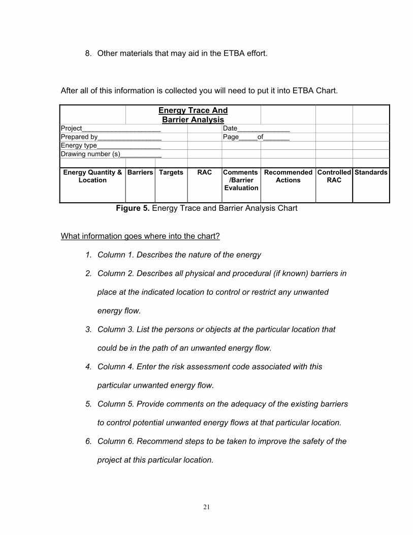
After all of this information is collected you will need to put it into ETBA Chart.
Energy Trace AndBarrier Analysis
Project_____________________ Date______________Prepared by_________________ Page_____of_______Energy type_________________Drawing number (s)___________
Energy Quantity &Location
Barriers Targets RAC Comments/Barrier
Evaluation
RecommendedActions
ControlledRAC
Standards
Figure 5. Energy Trace and Barrier Analysis Chart
What information goes where into the chart?
1. Column 1. Describes the nature of the energy
2. Column 2. Describes all physical and procedural (if known) barriers in
place at the indicated location to control or restrict any unwanted
energy flow.
3. Column 3. List the persons or objects at the particular location that
could be in the path of an unwanted energy flow.
4. Column 4. Enter the risk assessment code associated with this
particular unwanted energy flow.
5. Column 5. Provide comments on the adequacy of the existing barriers
to control potential unwanted energy flows at that particular location.
6. Column 6. Recommend steps to be taken to improve the safety of the
project at this particular location.

22
7. Column 7. Enter the risk assessment code after the actions
recommended in column 6 have been taken.
8. Column 8. Use this column to list any applicable codes, standards, or
regulations. (Stephenson, 2000, p. 150-151)
MORT
The MORT system is used by the TAC’s ground safety community and the
U.S. Air Force mainly. This is a very useful tool in accident investigations as well.
However it is very complex with over 1,500 different events and multiple transfers
to chose from. It tends to be overkill for some uses. Because MORT is so
complex it is was essential that a new approach be devised. That is how PET
(Project Evaluation Tree) was developed.
PET
Project Evaluation Tree otherwise known as PET was introduced in 1989.
It was first introduced to NASA’s general occupational safety community at the
National Safety Congress in Chicago. It was also introduced to: Safety
engineering students and the University of Houston as well as the U.S. Army
Corps of Engineers at a conference in Bethesda.
PET can be described as an analytical tree to be used primarily as a
graphic check in basically the same manner as a management oversight and risk
tree. PET is very simple compared to MORT’s 1,500 symbols and transfers. It
consists of less than 200 symbols and no transfers. This makes it much more

23
user friendly. The purpose of PET is to provide a relatively simple,
straightforward, and efficient method of performing an in-depth evaluation or
analysis of a project or operation.
The PET system is divided into three basic branches.
1. Procedures
2. Personnel
3. Plant and Hardware
There are some impute requirements needed for PET to work properly.
They are, detailed information on the procedures, personnel, and facilities and
hardware to be evaluated. The next needed information is, upstream documents
requiring the procedures and outlining the protocol for the generation, review,
distribution, and updating are also required. So you may ask what things are
needed to evaluate facilities and hardware? (This is just a few, do not assume
that this is a complete list)
1. Drawings
2. Procurement documents
3. Specifications
4. Test plans and records
5. System safety plans and records
6. Hazard analyses
7. Budget data

24
Note 1: The scope and depth of the analysis dictate the need for input data.
Note 2: The quality of the input data greatly influences the quality of the analysis.
In order to approach your newly collected data you must identify each procedure,
individual and/or organization, facility, an dpiece of equipment or hardware to be
analyzed and then systematically use the appropriate branch of the PET tree.
PET Analysis WorksheetPrepared by:_______ Purpose:__________ Change Analysis_____________Office Symbol:______ Operational Readiness________ Accident Investigation_________Date:_____________ Mission Failure______________ Inspection/Evaluation__________
Item no. ItemEvaluated
PETEvent
Color Problem/Comments
ResponsiblePerson/Agency
Status Final CompletionDate
Figure 6. PET Analysis Worksheet
What you should be able to evaluate after you have completed the chart.
1. Maintenance
2. Inspection
3. Operation for the facility
4. Hardware being designed
Where you should begin?
1. Define the scope of the analysis and the ground rules
2. Collect the appropriate input data
25
3. Organize the data into procedures, personnel, and facilities/hardware
4. Systematically evaluate they system or project using the PET users
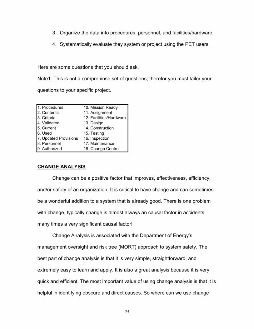
Here are some questions that you should ask.
Note1. This is not a comprehinse set of questions; therefor you must tailor your
questions to your specific project.
1. Procedures 10. Mission Ready2. Contents 11. Assignment3. Criteria 12. Facilities/Hardware4. Validated 13. Design5. Current 14. Construction6. Used 15. Testing7. Updated Provisions 16. Inspection8. Personnel 17. Maintenance9. Authorized 18. Change Control
CHANGE ANALYSIS
Change can be a positive factor that improves, effectiveness, efficiency,
and/or safety of an organization. It is critical to have change and can sometimes
be a wonderful addition to a system that is already good. There is one problem
with change, typically change is almost always an causal factor in accidents,
many times a very significant causal factor!
Change Analysis is associated with the Department of Energy’s
management oversight and risk tree (MORT) approach to system safety. The
best part of change analysis is that it is very simple, straightforward, and
extremely easy to learn and apply. It is also a great analysis because it is very
quick and efficient. The most important value of using change analysis is that it is
helpful in identifying obscure and direct causes. So where can we use change
26
analysis? We can use this process anywhere a technique for evaluating changes
and determining the need for counterchanges to keep the system in balance are
needed. In using the change analysis it is easy to determine the significance or
impact of the changes made.
This is also a very effective prevention tool. It provides an excellent
method for conducting reviews. It should be performed as part of the review
process at each review point in the system safety effort.
In order to use the change analysis it requires a detailed understanding of
the system before and after the changes are made. You will also need to have a
good understanding of the project and its description documents. You will need
to know what is in the description documents so we have provided a non-
collective list for the reader to view.
1. Analytical Trees
2. Narrative Descriptions
3. Block Diagram
4. Blueprints
5. Organization Structures
6. Job Descriptions
7. Personnel Qualifications
So you as the reader may ask what is the general approach and what are
the steps. For the general approach you can follow these guidelines. All changes
27
(that is, the differences between the present situation and the comparable
situation) are systematically listed. Next comes the instructions.
1. Determine the two situations to be compared
2. A comparable situation is to compare the accident situation with a
similar accident-free operation
3. Compare the accident situation with an idealized situation
Note1: The selection of an appropriate comparable situation is probably the most
difficult step in performing a change analysis, but this step is quite simple if the
change analysis is part of the review of the proposed changes.
Once you have completed selecting the comparable situation you should:
1. Collect sufficient information about the situation
2. Carefully list all the differences between the proposed and appropriate
comparable situation
3. After all the changes have been listed evaluate and analyze each of
them
4. Note each change
5. It is recommended to put into place, controls and countercontrols
6. Provide a summary of significant changes
28
COMMON CAUSE ANALYSIS FAILURE
The common cause analysis or otherwise known as common cause failure
is usually used to evaluate many failures that may have been caused by one
singe event, or it can be used to determine weather there was more than one
component that lead to the event.
“Common cause failures can be a shred environment or locations” (Stephenson,
2000, p. 264). If redundant systems are relied on you must have reliable
elements. These elements must not be subjected to having a single event or
common causal factor.
When approaching commons cause failure analysis it is imperative to
identify the critical systems or components. Once you have completed this step
you can place the information into the energy trace barrier analysis (ETBA) to
evaluate the system’s weak spots, unwanted energy flows, and barrier failures.
As a back up to this analization we can also use the project evaluation tree
(PET). This lets us evaluate an analyze common operating and maintenance
procedures.
CONCLUSION
In conclusion our safety efforts are never complete. We must always have
proactive mind set and continue the amazing advances in our safety world. We
must never allow blood priority to take precedence over our prior knowledge and
always be positive and open to new ideas.
29
DEFINITIONS:
All definitions were taken from this source, (Stephenson, 2000, p. 191-301)
AASE: American Society of Safety Engineers Dictionary of Terms Used in theSafety Profession
SSDC: System Safety Development Center Glossary of SSDC Terms andAcronyms
AFR 800-16: U.S. Air Force Regulation 800-16, USAF System Safety Programs(USAF)
MIL-STD-882: Military Standard 882B, System Safety Program Requirements(DOD)
NSTS 22245: National Space Transportation System, Methodology for Conductof NSTS Hazard Analyses (NASA)
Acceptable Risk: The residual risk remaining after controls have been applied toassociated hazards that have been identified, quantified to the maximum extentpracticable, analyzed, communicated to the proper level of management andaccepted after proper evaluation (SSDC).
Accident: An unwanted transfer of energy or an environmental condition which,due to the absence or failure of barriers and/or controls, produces injury topersons, property, or process (SSDC); as defined in NHB 5300.41 (1D-2), “Anunplanned event which results in an unsafe situation or operational mode” (NSTS22254); an unplanned and sometimes injurious or damaging even whichinterrupts the normal progress of an activity and is invariably preceded by anunsafe act or unsafe condition or some combination thereof. An accident may beseen as resulting from a failure to identify a hazard or from some inadequacy inan existing system of hazard controls (ASSE).
Assumed Risk: A specific, analyzed residual risk accepted at an appropriate levelof management. Ideally, the risk has had analysis of alternatives for increasingcontrol and evaluation of significance of consequences (SSDC).
Barrier: Anything used to control, prevent, or impede energy flows. Types ofbarriers include physical, equipment design, warning devices, procedures andwork processes, knowledge and skills, and supervision. Barriers may be used tocontrol or safety barriers or act as both (SSDC).
30
Component: As defined in NHB 5300.41 (ID-2), “A combination of parts, devices,and structures, usually self-contained, which performs a distinctive function in theoperation of the overall equipment. A ‘black box’ (NSTS)
Contractor: A private sector enterprise or the organizational element of DoD orany other Government agency engaged to provide services or products withinagreed limits specified by the MA (MIL-STD 882B)Corrective Action: As defined in NHB 5300.41 (1D-2), “Action taken to precludeoccurrence of an identified hazard or to prevent recurrence of a problem” (NSTS22254).
Critical Item: A single failure point and/or a redundant element in a life-ormission-essential application where:
1. Redundant elements cannot be checked out during the normal groundturnaround sequence
2. Loss of a redundant element is not readily detectable in flight3. All redundant elements can be lost by a single credible cause or event
such as contamination or explosion
Critical Items List (CIL): A listing comprised of all critical items identified as aresult of performing the FMEA (NSTS 22254).
Criticality: The categorization of a hardware item by the worst case potentialdirect effect of failure of that item. In assigning hardware criticality, the availabilityof redundancy modes of operation is considered. Assignment of functionalcriticality, however, assumes the loss of all redundant hardware elements (NSTS22254).
Damage: The partial or total loss of hardware caused by component failure:exposure of hardware to heat, fire, or other environments; human errors; or otherinadvertent events or conditions (MIL-STD-882B).
Failure: As defined in NHB 5300.41 (1D-2), “The inability of a system,subsystem, component, or part to perform its required function within specifiedlimits, under specified conditions for a specified duration” (NSTS 22254).
Failure Modes and Effect Analysis (FMEA): A systematic, methodical analysisperformed to identify and document all identifiable failure modes at a prescribedlevel and to specify the resultant effect of the failure mode at various levels ofassembly (NSTS 22254); the failure of malfunction of each system component isidentified, along with the mode of failure (e.g., switch jammed in the “on”position). The effects of the failure are traced through the system and theultimate effect on task performance is evaluated. Also called failure mode andeffect critically analysis (ASSE); a basic system safety technique wherein thekinds of failures that might occur and their effect on a system by the failure of asingle component, such as a register or a hydraulic valve (SSDC).
31
Fault Tree: An analytical tree used to determine fault. These may be used inaccident/incident investigation or to determine accident potential before one hasoccurred. (SSDC)
Hazard: A condition that is prerequisite to a mishap (MIL-STD-882B); a conditionor changing set of circumstances that presents a potential for injury, illness, orproperty damage. The potential or inherent characteristics of an activity,condition, or circumstance which can produce adverse or harmful consequences(ASSE); a condition that is prerequisite to a mishap (DODI 50000.36) (AFR 800-16); the presence of a potential risk situation caused by an unsafe act orcondition (NSTS 22254); the potential for energy flow(s) to result in an accidentor otherwise adverse consequence (SSDC).
Hazard Analysis: The functions, steps, and criteria for design and plan of work,which identify hazards, provide measures to reduce the probability and severitypotentials, identify residual risks, and provide alternative methods of furthercontrol (SSDC); a process of examining a system, design, or operation todiscover inherent hazards, characterizing them as to level of risk and identifyingrisk-reduction alternatives (AFR 800-16); the determination of potential sourcesof danger and recommended resolutions in a timely manner for those conditionsfound in either the hardware/software systems, the person-machine relationship,or both, which cause loss of personnel capability, loss of system, or loss of life orinjury to the public (NSTS 22254).
Hazard Analysis Techniques: Methods used to identify and evaluate hazards.These techniques cover the complete spectrum from qualitative preliminaryhazard studies to system logic diagrams containing quantitative probabilities ofmishap (AFR 800-16)
Hazard Levels: The hazard level assigned to the identified hazard prior toapplying the hazard reduction precedence sequence (HRPS) corrective action.Include hazard carried over for tracing from previous phases:
1. Catastrophic – No time or means are available for corrective action2. Critical – May be counteracted by emergency action performed in a
timely manner3. Controlled – Has been countered by appropriate design, safety
devices, alarm/caution and warning devices, or specialautomatic/manual procedures.
Hazardous Event: An occurrence that creates a hazard (MIL-STD-882B)
Hazardous Event Probability: The likelihood, expressed in quantitative orqualitative terms, that a hazardous event will occur (MIL-STD-882B)

32
Hazard Probability: The aggregate probability of occurrence of the individualhazardous events that create a specific hazard (MIL-STD-882B)
Hazard Report Closure Classification:1. Eliminated Hazard – A hazard that has been eliminated by removing
the hazard source or by deleting the hazardous operations2. Controlled Hazard – The likelihood of occurrence has been reduced to
an acceptable level by implementing the appropriate hazard reductionprecedence sequence to comply with program requirements
3. Accepted Risk – Hazard which has not been counteracted byredundancy, purge provisions, appropriate safety factors,containment/isolation provision, backup system/operation, safetydevices, alarm/caution and warning devices, or specialautomatic/manual procedures. Catastrophic hazards, critical hazards,hazards resulting from failure to meet program requirements, andSingle Failure Points (SFPs) in emergency systems will bedocumented. A hazard will be classified as an “accepted risk” only after
a. all reasonable risk avoidance measures have been identified,studied and documented
b. project/program management has made a decision to acceptthe risk on the basis of documented risk acceptance rationale
c. safety management has concurred in the accepted risk rational(NSTS 22254)
Hazard Report Status1. Closed – Corrective action to eliminate or control the hazard is
completed, evaluated, and verified and management actions to acceptthe safety risks are completed. Actions taken, organizations whichperformed actions and completion dates are to be documented in thisdata element
2. Open – Corrective action evaluation and verification is in progress. Thestatus shall remain open until management has reviewed the actionstaken and accepted the safety risk. Actions required, organizationdocumented in this data element (NSTS 22254).
Hazard Severity: An assessment of the worst credible mishap that could becaused by a specific hazard (MIL-STD-882B).
Human Factors; Human Factors Engineering: The application of the humanbiological and psychological sciences in conjunction with the engineeringsciences to achieve the optimum mutual adjustment of man and his work, thebenefits being measured in terms of human efficiency and well being. Theprinciple disciplines involved are anthropometry, physiology, and engineering(SSDC).
33
Implementing Command: The command or agency designated by HQ USAF tomanage an acquisition program (AFR 800-2); AFR 800-4 includes modificationprograms (AFR 800-16)
Loss Of Personal Capability: As defined in NHB 5300.41(1D-2); “Loss ofpersonnel function resulting in inability to perform normal or emergencyoperations. Also includes loss or injury to the public” (NSTS 22254).Loss Of Vehicle System: As defined in NHB 5300.41(1D-2), “Loss of thecapability to provide the level of system performance required for normal oremergency operations” (NSTS 22254).
Management Oversight and Risk Tree (MORT): A formal, disciplined logic ordecision tree to relate and integrate a wide variety of safety conceptssystematically. As an accident analysis technique, it focuses on three mainconcerns: specific oversights and omissions, assumed risks, and generalmanagement system weakness (SSDC).
Managing Activity: The organizational element of DoD assigned acquisitionmanagement responsibility for the system, or prime or associate contractors orsubcontractors who wish to impose system safety tasks on the suppliers (MIL-STD 882B).
Mishap: An unplanned event or series of events that results in death, injury,occupational illness, or damage to or loss of equipment or property (MIL-STD-882B); an unplanned event or series of events that result in death, injury,occupational illness, or damage to or loss of equipment or property, or damage tothe environment. (DODI 5000.36) (AFR 800-16); a synonym for accident. Usedby some government organizations, including NASA and DOD (SSDC).
Mission Events: Time-oriented flight operations defined in flight checklists (NSTS22254).
Near Miss: An incident or an accident resulting in minor consequences althoughthe potential for serious consequences was high (SSDC).
Off The Shelf Item: An item determined by a material acquisition decisionprocess review (DoD, Military Component, or subordinate organization asappropriate) to be available for acquisition to satisfy an approved materialrequirement with no expenditure of funds for development, modification, orimprovement (e.g., commercial products, material developed by otherGovernment agencies, or materiel developed by other countries). This item maybe produced by the contractor or furnished to the contractor as Government-furnished equipment (GFE) or Government-furnished property (GFP) (MIL-STD-882B).
34
Operating And Support Hazard Analysis (O&SHA): As described in NHB 1700.1(V1-A) and this document. The PHA is to identify safety-critical areas, to identifyand evaluate hazards, and to identify the safety design and operationrequirements need in the program concept phase (NSTS 22254).
Preliminary Hazard Analysis (PHA): As described in NHB 1700.1 (V1-A) and thisdocument. The PHA is to identify safety-critical areas, to identify and evaluatehazards, and to identify the safety design and operation requirements needed inthe program concept phase (NSTS 22254).
Program Manager: The single Air Force manager (system program director,program or project manager, or system, system program, or item manager)during any specific phase of acquisition life cycle (AFR 800-2) (AFR 800-16).
Quantified Safety Requirements: A desired, predictable, and demonstrable levelof safety, usually expressed as a mishap rate or probability of mishap (AFR 800-16).
Residual Risk: Risk remaining after the application of resources for prevention ormitigation (SSDC).
Risk: Mathematically, expected loss; the probability of an accident multiplied bythe quantified consequence of the accident (SSDC); an expression of thepossibility of a mishap in terms of hazard severity and hazard probability (MIL-STD 882B); note: Hazard exposure is sometimes included (AFR 800-16) asdefined in NHB 5300.4 (1D-2), “The chance (qualitative) of loss of personnelcapability, loss of system, or damage to or loss of equipment or property” (NSTS22254); a measure of both the probability and the consequence of all hazards ofan activity or condition. A subjective evaluation of relative failure potential. Ininsurance, a person or thing insured (ASSE).
Risk Acceptance: The acceptance by an individual or organization of a level ordegree of risk which has been identified as the potential consequence of a givencourse of action (ASSE).
Risk Analysis: The quantification of the degree of risk (SSDC).
Risk Assessment: The combined functions of risk analysis and evaluation(SSDC).
Risk Assessment: The amount or degree of potential danger perceived by agiven individual when determining a course of action to accomplish a given task(ASSE).
35
Risk Evaluation: The appraisal of the significance or consequences of a givenquantitative measure of risk (SSDC).
Risk Management: The process, derived though system safety principles,whereby management decisions are made concerning control and minimizationof hazards of residual risks (SSDC); the professional assessment of all losspotentials in an organizations’ structure and operations, leading to theestablishment and the administration of a comprehensive loss control program.Related to and dependent upon an ongoing program of accident prevention, riskmanagement encompasses the selection of purchased insurance, self-insurance,and assumed risk. Its goal is to reduce losses to an acceptable minimum at thelowest possible cost (ASSE).
Risk Visibility: The documentation of a risk related to hardware, operations,procedures, software, and environment that provides Safety, project offices, andprogram management with the ability to evaluate accepted risks associated withplanned operations (NSTS 22254).
Safe: A condition wherein risks are as low as practicable and present nosignificant residual risk (SSDC).
Safety: The control of accidental loss and injury (SSDC); freedom from thoseconditions that can cause death, injury, occupational illness, or damage to or lossof equipment or property (MIL-STD-882B); a general term denoting anacceptable level of risk of, relative freedom from, and low probability of harm(ASSE); as defined in NHB 5300.4 (1D-2), “Freedom from chance of injury orloss of personnel, equipment or property” (NSTS 22254).
Safety Analysis: A systematic and orderly process for the acquisition andevaluation of specific information pertaining to the safety of an system (NSTS22254).
Safety Analysis (Hazard Analysis): The entire complex of safety (hazard)analysis methods and techniques ranging from relatively informal job and tasksafety analyses to large complex safety analysis studies and reports (SSDC).
Safety Analysis Report (SAR): A document prepared to document the results ofhazard analysis performed on a system, subsystem or operation. The specificminimum data elements for an SAE will be defined by data deliverablerequirements for the program or project (NSTS 22254).
Safety Critical: As defined in NHB 5300.4(1D-2), “Facility, support, test, and flightsystems containing:
1. Pressurized vessels, lines, and components2. Propellants, including cryogenics3. Hydraulics and pneumatics

36
4. High voltages5. Radiation sources6. Ordnance and explosive devices or devices used for ordnance and
explosive checkout7. Flammable, toxic, cryogenic, or reactive elements or compounds8. High temperatures9. Electrical equipment that operates in the area where flammable fluids
or solids are located10. Equipment used for handling program hardware11. Equipment used for personnel walking and work platforms” (NSTS
22254).
Safety-Critical Computer Software Components: Those computer softwarecomponents (processes, functions, values or computer program state) whoseerrors (inadvertent or unauthorized occurrence, failure to occur when required,occurrence out of sequence, occurrence in combination with other functions, orerroneous value) can result in a potential hazard, or loss of predictability orcontrol of a system (MIL-STD 882B).
Single Failure Point: As defined in NHB 5300.4 (1D-2), “A single item ofhardware, the failure of which would lead directly to loss of life, vehicle ormission. Where safety consideration dictates that an abort be initiated when aredundant item fails, that element is also considered a single failure point” (NSTS22254).
Space Transportation System: An integrated system consisting of the SpaceShuttle (Orbiter, External Tank (ET), Solid Rocket Booster (SRB), and flight kits)),upper stages, Spacelab, and any associated flight hardware and software (NSTS22254).
Subsystem: An element of a system that, in itself, may constitute a system (MIL-STD-882B).Subsystem Hazard Analysis (SSHA): As described in NHB 1700.1(V1-A) and thisdocument. The SSHA is to identify hazards to personnel, vehicle and othersystems caused by loss of function, energy source, hardware failures, personnelaction or inaction, software deficiencies, interactions of components within thesubsystem, inherent design characteristics such as sharp edges, andincompatible materials, and environmental conditions such as radiation and sand(NSTS 22254).
Supporting Command: The command assigned responsibility for providinglogistics support; it assumes program management responsibility for theimplementing command (AFR 880-2) (AFR 800-16).
System: A composite, at any level of complexity, of personnel, procedures,materials, tools, equipment, facilities, and software, The elements of this
37
composite entity are used together in the intended operational or supportenvironment to perform a given task or achieve a specific production, support, ormission requirement (MIL-STD-882B); a set of arrangement of components sorelated or connected as to form a unity or organic whole. A set of facts,principles, rules, etc., classified or arranged in a regular, orderly form so as toshow a logical plan linking the various parts. A method, plan, or classification. Anorderly arrangement of interdependent activities and related procedures whichimplements and facilitates the performance of a major activity or organization. Aset of components, humans or machines or both, which has certain functions andacts and interacts, one in relation to another, to perform some task or tasks in aparticular environment or environments. Any configuration of elements in whichthe behavior properties of the whole are functions of both the nature of theelements and the manner in which they are combined (ASSE).
System Analysis (Safety Analysis): The formal analysis of a system and theinterrelationships among its various parts (including plant and hardware, policiesand procedures, and personnel) to determine the real and potential hazardswithin the systems, and suggest ways to reduce and control those hazards(SSDC).
System Hazard Analysis (SHA): As described in NHB 1700.1 (V1-A) and thisdocument. The SHA is identical to the SSHA but at the system level. Once thesubsystem levels have been established, a combination of subsystems comprisea system. In turn, a group of systems may comprise another system until the topsystem is identified (NSTS 22254).
System Safety: The application of engineering and management principles,criteria, and techniques to optimize safety within the constraints of operationeffectiveness, time, and cost throughout all phases of the system life cycle (DODI5000.36) (AFR 800-16); an approach to accident prevention which involves thedetection of deficiencies in system components which have an accident potential(ASSE); as defined in NHB 5300.4 (1D-2), “The optimum degree of riskmanagement within the constrains of operation effectiveness, time and costattained thought the application of management and engineering principledthroughout all phases of a program (NSTS 22254); safety analysis (usuallyspecialized and sophisticated) applied as an adjunct to design of an engineeredsystem. While many associate system safety primarily with the hardware portionof the system, it includes all aspects of configuration control (SSDC).
System Safety Analysis: The safety analysis of a complex process or system bymeans of a diagram or model that provides a comprehensive view of theprocess, including its principal elements and the ways in which they interrelate(ASSE).
System Safety Engineer: An engineer who is qualified by training and/orexperience to perform system safety engineering tasks (MIL-STD-882B).
38
System Safety Engineering: An engineering discipline requiring specializedprofessional knowledge and skills in applying scientific and engineeringprinciples, criteria, and techniques to identify and eliminate hazards, or reducethe risk associated with hazards (MIL-STD-882B).
System Safety Group/Working Group: A formally chartered group of persons,representing organizations associated with the system acquisition program,organized to assist the MA system program manager in achieving the systemsafety objectives. Regulations of the Military Components define requirements,responsibilities, and memberships (MIL-STD-882B).
System Safety Management: An element of management that defines the systemsafety program requirements and ensures the planning, implementation andaccomplishments of system safety tasks and activities consistent with the overallprogram requirements (MIL-STD-882B).
System Safety Manager: A person responsible to program management forsetting up and managing the system safety program (MIL-STD-882B).
System Safety Program: The combined tasks and activities of system safetymanagement and system safety engineering that enhance operationaleffectiveness by satisfying the system safety requirements in a timely, cost-effective manner throughout all phases of the system life cycle (MIL-STD-882B).
System Safety Program Plan: A description of the planned methods to be usedby the contractor to implement the tailored requirements of this standard,including organizational responsibilities, resources, methods of accomplishment,milestones, depth of effort, and integration with other program engineering andmanagement activities and related systems (MIL-STD-882B).
User: Identified and authorized NASA, element contractor, or integrationcontractor personnel; flight crew equipment annalist; Orbiter experiments analyst;payload accommodations analyst; detailed secondary objective annalist; or RMSanalyst (not inclusive) that have necessary access to the intercenter hazard database system (NSTS 2254)

39
40
REFERENCES
Stephenson, J. (2000) A practical guide for planning, managing, andconduction system safety programs.Johnson, William G. 1973. MORT, The Management Oversight and RiskTree.
Washington, D.C.: U.S. Atomic Energy Commission.Medford, Fred. 1973. History of the system safety society (SSS). HazardPrevention 9(5):38-40.Moriarty, Brian, and Roland, Harold E. 1983. System Safety Engineering andManagement. New York: John Wiley & Sons.U.S Air Force. 1987. SDP 127-1: System Safety Handbook for the AcquisitionManager. Los Angeles: HQ Space Division/SE.
41
FIGURE REFERANCES
Figure 1: Stephenson, 2000, p. 11
Figure 2: Stephenson, 2000, p. 70
Figure 3: Stephenson, 2000, p. 70
Figure 4: Stephenson, 2000, p. 156
Figure 5: Stephenson, 2000, p. 150
Figure 6 Stephenson, 2000, p. 196

42