the effect of floating-potential conductors on the electric field near overhead transmission lines
TRANSCRIPT
at SciVerse ScienceDirect
Journal of Electrostatics 70 (2012) 339e345
Contents lists available
Journal of Electrostatics
journal homepage: www.elsevier .com/locate/elstat
The effect of floating-potential conductors on the electric field near overheadtransmission lines
Deming Yu a,b, Shuwei Wan a,b,*, Fangdong Chen c, Xingming Bian a,b, Lan Chen a,b, Mark MacAlpine a,Jifei Zhang c, Lin Zhang a,b, Liming Wang a,b
aDepartment of Electrical Engineering, Tsinghua University, 100084 Beijing, PR Chinab Laboratory of Advanced Technology of Electrical Engineering and Energy Graduate School at Shenzhen, Tsinghua University 518055 Shenzhen, Guangdong Province, PR ChinacBeijing Extra High Voltage Company, North China Grid Company Limited, 102488 Beijing, PR China
a r t i c l e i n f o
Article history:Received 8 February 2012Received in revised form9 February 2012Accepted 4 April 2012Available online 7 May 2012
Keywords:Floating conductorTransmission lineFinite-elementElectric fieldHelicopter line patrol
* Corresponding author. Department of Electrical Esity, 100084 Beijing, PR China. Tel.: þ86 138 1049 140
E-mail address: [email protected] (S. Wan).
0304-3886/$ e see front matter � 2012 Elsevier B.V.doi:10.1016/j.elstat.2012.04.003
a b s t r a c t
The use of helicopters as platforms equipped with infrared and UV detection, digital cameras and otherinspection equipment is an effective method of increasing the efficiency and effectiveness of trans-mission line inspection. However, as a ’floating-potential conductor’ near to a high-voltage transmissionline, a helicopter causes distortion of the local electric field, with regions of high electric field near thehelicopter’s surface where the curvature is high. In this paper, these fields are investigated both bycalculation and experimentally, using a simple metal sphere, and then a model of a helicopter, placednear to a short length of energized transmission line conductor.
� 2012 Elsevier B.V. All rights reserved.
1. Introduction
Power transmission lines are a key part of the power system andare exposed all the year round to the prevailing weather conditions.It follows that they are more prone to faults than other parts of thesystem. Furthermore visual monitoring of the lines may beextremely difficult where the terrain over which the lines runpresent great difficulties for the workers to access. This is particu-larly so in China where the necessarily very long transmission linesmay traversemountains, swamps, rivers and forests much of whichare relatively unpopulated and hard to reach [1e4]. Meanwhile, thedevelopment of the smart grid in China requires higher stabilityand reliability of power delivery [5,6]. Helicopters have the abilityto ascend and descend vertically and to hover motionless at anyheight, making them ideally suited for monitoring overhead lines[4,6e9]. Using a helicopter as a moving platform equipped withinfrared, visual and UV video cameras and other equipment for linepatrol duties is an efficient way to improve the efficiency andaccuracy of transmission line monitoring [10e13]. The helicopterenables close observation of the conductors, insulators, fittings and
ngineering, Tsinghua Univer-9.
All rights reserved.
towers, while with infrared and UV inspection systems, operatorscan clearly see where corona and other discharges are occurring[14e18].
However, when a helicopter is close to a transmission line, itwill, as an isolated conductor, cause a distortion of the electric fielddistribution. This will be particularly important around those partsof the helicopter having a small radius of curvature where the fieldwill be high, perhaps causing localized discharges and the possi-bility of a breakdown between line, helicopter and ground, with theconsequent dangers to helicopter, personnel and equipment.
Calculations concerning floating conductors have been consid-ered by several investigators [19e23]: Tadashi used a chargesimulation method to determine the field near a floating conductortouching two dielectric media [19]; Lucian employed a boundary-element method to determine the field in the region betweena charged body and a conducting disc at a floating-potential [20].Also several authors have considered the fields near or below 3-phase and DC transmission lines with reference to sag andground characteristics [24e29], but none appear to have consid-ered the field distortion due to floating-potential conductors neartransmission lines. In this paper the effect on the electric fieldaround floating-potential conductors near to transmission lines isconsidered both experimentally and by numerical calculation. Thetwo cases considered are a sphere and a model helicopter.

15m
6.8m
4-conductor bundle18m
Fig. 1. The location of the quad bundle.
Fig. 2. The Holaday HI-3604 Survey Meter.
D. Yu et al. / Journal of Electrostatics 70 (2012) 339e345340
2. Experiments
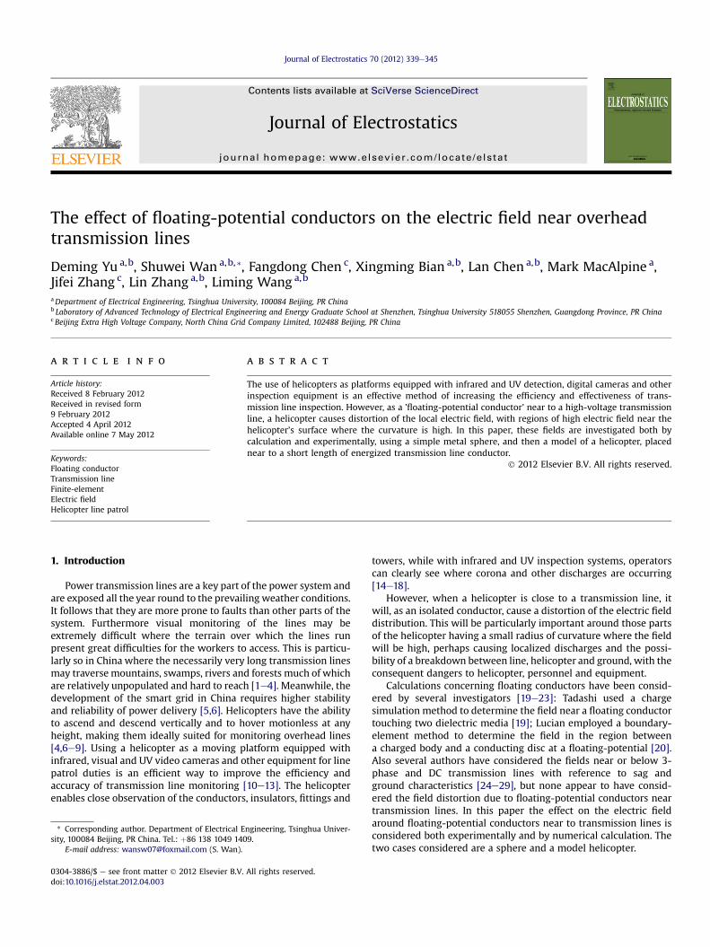
The experiments were carried out in a shielded hall of dimen-sions 66 m � 30 m � 18 m. The ambient temperature was in therange 16e18 �C for the tests. The air pressure was between 100.2and 100.6 kPa, and the relative humidity was in the range 40%e50% throughout. The overhead transmission line used was a 4-conductor bundle, type LGJ-400/35, of length 15 m, which wasinstalled at the center of the hall about 7 m above the ground asshown in Fig. 1. The parameters of the quad bundle are shown inTable 1.
The field was measured by a Holaday HI-3604 Survey Meterwhich can measure both electric and magnetic fields at 50/60 Hz,and is shown in Fig. 2a [30,31]. A 1000 kV adjustable frequencytransformer was used as the power supply (Fig. 3).
The field meter was connected to an insulated rod supported onan insulated trolley which could be moved to measure the field atthe required point. The fieldmeter and insulated rodmay be seen inFig. 4a.
As the external material of a helicopter is mainly metal, when itis used to observe transmission lines, it will be at a floating-potential; the charge in the field would redistribute because ofpolarization effect; so the floating-potential conductor woulddistort the surrounding electric field and potential. To study thiseffect, a simple geometry was used initially: a spherical metal ballwith a diameter of 0.65 m. Later the experiment and calculationwere extended by replacing the sphere with a simplified 1:10model of a helicopter based on the Bell 206 line patrol helicopter.For both the experiments and calculations the sphere and thehelicopter model were placed at various distances from the trans-mission line, but at the same height above the ground plane. Thefloating-potential conductors were hung with an insulating ropemade up of cotton. The quad bundle, field meter and spheremay beseen in Fig. 4a. A cross-section of the hall showing the positioningof the transmission line model and the metal sphere is shown inFig. 4b.
3. Numerical calculation
The experiments were carried out in a shielded hall which wasrepresented in the calculation by a cuboid of the same dimensions
Table 1Parameter of 4 � LGJ-400/35.
External diameter of sub-conductor Bundle spacinga
26.8 mm 450 mm
a Distance between the center of a conductor and its nearest-neighborconductors.
whose six boundary faces were set to 0 V (grounded). The chargedensity of the air in the hall was set to zero, the metal sphere andhelicopter model were regarded as floating-potential conductorswith no overall charge before discharge corona. The set-up was asindicated in Fig. 5, with the transmission line 6.8 m above theground.
Fig. 3. The 1000 kV adjustable frequency transformer.
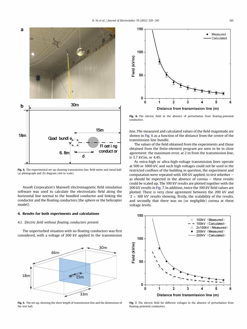
Fig. 4. The experimental set-up showing transmission line, field meter and metal ball:(a) photograph and (b) diagram (not to scale).
Fig. 6. The electric field in the absence of perturbation from floating-potentialconductors.
D. Yu et al. / Journal of Electrostatics 70 (2012) 339e345 341
Ansoft Corporation’s Maxwell electromagnetic field simulationsoftware was used to calculate the electrostatic field along thehorizontal line normal to the bundled conductor and linking theconductor and the floating conductors (the sphere or the helicoptermodel).
4. Results for both experiments and calculations
4.1. Electric field without floating conductors present
The unperturbed situation with no floating conductors was firstconsidered, with a voltage of 200 kV applied to the transmission
Fig. 5. The set-up, showing the short length of transmission line and the dimensions ofthe test hall.
line. The measured and calculated values of the field magnitude areshown in Fig. 6 as a function of the distance from the centre of thetransmission line bundle.
The values of the field obtained from the experiments and thoseobtained from the finite-element program are seen to be in closeagreement: the maximum error, at 2 m from the transmission line,is 3.7 kV/m, or 4.4%.
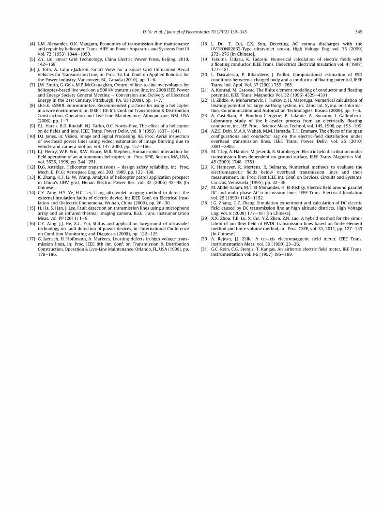
As extra-high or ultra-high-voltage transmission lines operateat 500 or 1000 kV, and such high voltages could not be used in therestricted confines of the building in question, the experiment andcomputationwere repeated with 100 kV applied, to test whether eas should be expected in the absence of corona e these resultscould be scaled up. The 100 kV results are plotted together with the200 kV results in Fig. 7. In addition, twice the 100 kV field values areplotted. There is very close agreement between the 200 kV and‘2 � 100 kV’ results showing, firstly, the scalability of the results,and secondly that there was no (or negligible) corona at thesevoltage levels.
Fig. 7. The electric field for different voltages in the absence of perturbation fromfloating-potential conductors.

0
20
40
60
80
100
1 2 3 4 5 6
Distance of sphere from the line (m)
Su
rface field
en
han
cem
en
t (%
)
Measured - line side
Measured - far side
Calculated - line sideCalculated - far side
Fig. 9. The field enhancement at the surface of the sphere near the transmission lineand at the surface on the far side of it.
Fig. 10. The dimensions of the Bell 206 helicopter.
D. Yu et al. / Journal of Electrostatics 70 (2012) 339e345342
4.2. Electric field in the presence of a floating-potential metal ball
Inevitably, a floating-potential conductor will cause a distortionof the original electric field distribution, particularly close to thoseparts of the surface having a small radius of curvature, where the
Fig. 8. Comparison of the measured and calculated values of the field with the metalsphere at various distances from the transmission line. The calculated values of thefield in the absence of the metal sphere are also plotted for reference.

D. Yu et al. / Journal of Electrostatics 70 (2012) 339e345 343
field will be greater. A metal ball, suspended by an insulating ropemade up of cotton (and so at a floating-potential), was hung at thesame height above ground as the transmission line (Fig. 4). Theelectric field distribution was measured and computed as beforewith a voltage of 200 kV applied to the line, and the results areshown in Fig. 8 for several different values of d, the distancebetween the transmission line conductor and the center of thesphere (Fig. 4b). The agreement is good, improving with distanceaway from the transmission line.
Consideration of Fig. 8 shows that the perturbation of the fieldcaused by the presence of the sphere only extends a short distanceeither side of the sphere: most of the disturbance is confined toa distance equal to the radius and is negligible after a distance equalto the diameter of the sphere, 0.65 m.
The difference between the electric field at the surface of thesphere nearest to the transmission line, and the field there in theabsence of the spheree the field enhancement due to the presenceof the sphere e are plotted in Fig. 9 for both experimental andcomputational results, and for the various positions of the sphere.The difference between the electric field at the surface of the spherefurthest from the transmission line, and the field there without thesphere’s presence, are also plotted.
Near the sphere the calculated field values are consistentlyhigher than the experimental ones by some 20%. Away from thesphere the differences decrease to less than 5%. The greaterdiscrepancies near the sphere where the field increases rapidly areperhaps because any small positioning errors of the meter up ordown, or sideways, or away from the spherewill cause a decrease inthe measured field. Possibly the effect of the finite size of the metal
Fig. 11. Helicopter Model.
parts of the electric field meter itself may lower the reading ina non-linear and rapidly-changing field.
4.3. Electric field in the presence of a floating-potential helicoptermodel
Since the wing, skid, tail and other parts with small radii ofcurvature will have a high field close to them; these parts wereaccurately modeled in the finite-element calculations, in order toobtain reliable results, using the dimensions and layout shown inFig. 10. The fuselage, and other parts which affect the electric field
Fig. 12. Comparison of the measured and calculated values of the field with the modelhelicopter at various distances from the transmission line. The calculated values of thefield in the absence of the helicopter model are also plotted for reference.

0
50
100
150
200
250
300
1 2 3 4
Distance of helicopter from line (m)
Ro
to
r tip
fie
ld
e
nh
an
ce
me
nt (%
)
Measured - line sideMeasured - far sideCalculated - line sideCalculated - far side
Fig. 13. Effect of model helicopter on the space field.
D. Yu et al. / Journal of Electrostatics 70 (2012) 339e345344
less, were simplified in the model used for the computation, asshown in Fig. 11a; and similarly in the model built for the experi-ments (and shown in Fig. 11b). The diameter of the cylindrical cabinwas 0.19 m.
0
50
100
150
200
0 2 4 6 8
Distance from transmission line (m)
Vo
lta
ge
(k
V)
d = 2md = 4m
0
50
100
150
200
Vo
ltag
e (kV
)
Distance from transmission line (m)
d = 1.5m
d = 2.7m
a
b
Fig. 14. The voltage along the line from transmission line to and past the model. (a)The voltage along the line from transmission line to and past the sphere for the casewhere it was 2 and 4 m away from the transmission line. (b)The voltage along the linefrom transmission line to and past the helicopter for the case where it was 1.5 and2.7 m away from the transmission line.
The measurement of the field in the presence of the helicopterwas carried out in the same manner as with the sphere. Again thevoltage applied to the line was 200 kV.The measurement lineextended from the transmission line in the normal direction andhorizontally towards the rotor blades.
The electric field distribution was measured and computed asbefore and the results are shown in Fig. 12 for several differentvalues of d, the distance between the transmission line conductorand the helicopter model’s rotor axle. The agreement is good,improving with distance away from the transmission line.
Fig. 12 also indicates shows that the perturbation of the fieldcaused by the presence of the helicopter model only extendsa distance either side of the model equal to the length of the rotorblades and is negligible after a distance equal to the diameter sweptby the rotors, 1.1 m.
The curves in Fig. 13 indicate that, as expected, the field isgreatly enhanced at the tips of the rotor blades. Again, as was thecase with the sphere, the calculated field is higher than themeasured field in the regions where the field is rapidly-changing.
4.4. The potential of the conductors
By integrating the electric field the potential drop away from theline could be determined, as shown in Fig. 14 (a) for d ¼ 2 and 4 m(metal sphere), and Fig. 14 (b) for d ¼ 1.5 and 2.7 m (helicoptermodel). Clearly the floating-potential of the conductor is close tothat which would obtain at the position of its center, if it wereabsent.
5. Conclusion
In this paper the effects of a floating-potential conductor, near toa transmission line, on the electric field were studied both byexperiment and by finite-element computation. An isolated metalsphere and a model of a helicopter were used as the floating-potential conductors and were placed near, and at the sameheight as, a short length of overhead transmission line.
(1) It was confirmed that, in the absence of corona, the value of theelectric field is proportional to the excitation voltage of thetransmission line, so that a system may be modeled and thenscaled up.
(2) The effect of the floating conductor on the electric field isconsiderable close to its surface, but diminishes rapidly awayfrom it, so that at a distance away from the sphere equal to itsdiameter, the effect is negligible. Similarly, for the helicopter,the effect on the field is negligible at a distance equal to thediameter of the circle swept out by the rotor blades.
(3) Close to the surface of the floating-potential conductor spherethe field was approximately doubled, while with the helicoptermodel the increase was even greater, with its more complexshape and in particular the effect of the rotor blades.
(4) The actual potential of these floating-potential conductorsappeared to be close to what would be found at the position ofits centroid, if the floating conductor were absent.
References
[1] Y.B. Shu, Y. Hu, Research and application of the key technologies of UHV ACtransmission lines, in: , Proc. CSEE, vol. 27, 2007, pp. 1e7 [In Chinese].
[2] Y.B. Shu, Y. Hu, Maintenance and live working technology for ultra highvoltage transmission line, High Voltage Eng. vol. 33 (2007) 1e6 [In Chinese].
[3] S.Y. Lu, Y.P. Li, W. Qi, Robotic live-working for electric power lines mainte-nances, in: 4th IEEE Conf. on Industrial Electronics and Applications, Xi’an,China (2009), pp. 1716e1719.
D. Yu et al. / Journal of Electrostatics 70 (2012) 339e345 345
[4] L.M. Alexander, O.K. Mangum, Economics of transmission-line maintenanceand repair by helicopter, Trans. AIEE on Power Apparatus and Systems Part IIIVol. 72 (1953) 1044e1050.
[5] Z.Y. Liu, Smart Grid Technology, China Electric Power Press, Beijing, 2010,142e168.
[6] J. Toth, A. Gilpin-Jackson, Smart View for a Smart Grid Unmanned AerialVehicles for Transmission Line, in: Proc. 1st Int. Conf. on Applied Robotics forthe Power Industry, Vancouver, BC, Canada (2010), pp. 1e6.
[7] J.W. Smith, G. Gela, M.F. McGranaghan, Control of line-to-line overvoltages forhelicopter-based live work on a 500 kV transmission line, in: 2008 IEEE Powerand Energy Society General Meeting e Conversion and Delivery of ElectricalEnergy in the 21st Century, Pittsburgh, PA, US (2008), pp. 1e7.
[8] I.E.E.E. ESMOL Subcommittee, Recommended practices for using a helicopterin a wire environment, in: IEEE 11th Int. Conf. on Transmission & DistributionConstruction, Operation and Live-Line Maintenance, Albuquerque, NM, USA(2006), pp. 1e7.
[9] E.L. Harris, B.D. Rindall, N.J. Tarko, O.C. Norris-Elye, The effect of a helicopteron dc fields and ions, IEEE Trans. Power Deliv. vol. 8 (1993) 1837e1841.
[10] D.I. Jones, in: Vision, Image and Signal Processing. IEE Proc, Aerial inspectionof overhead power lines using video: estimation of image blurring due tovehicle and camera motion, vol. 147, 2000, pp. 157e166.
[11] L.J. Henry, W.F. Eric, R.W. Bruce, M.R. Stephen, Human-robot interaction forfield operation of an autonomous helicopter, in: Proc. SPIE, Boston, MA, USA,vol. 3525, 1998, pp. 244e251.
[12] D.G. Astridge, Helicopter transmissions e design safety reliability, in: Proc.Mech. E, Pt.G: Aerospace Eng, vol. 203, 1989, pp. 123e138.
[13] K. Zhang, H.F. Li, W. Wang, Analysis of helicopter patrol application prospectin China’s UHV grid, Henan Electric Power Res. vol. 32 (2006) 45e48 [InChinese].
[14] C.Y. Zang, H.S. Ye, H.C. Lei, Using ultraviolet imaging method to detect theexternal insulation faults of electric device, in: IEEE Conf. on Electrical Insu-lation and Dielectric Phenomena, Wuhan, China (2009), pp. 26e30.
[15] H. Ha, S. Han, J. Lee, Fault detection on transmission lines using a microphonearray and an infrared thermal imaging camera, IEEE Trans. InstrumentationMeas. vol. PP (2011) 1e9.
[16] C.Y. Zang, J.J. He, X.G. Yin, Status and application foreground of ultraviolettechnology on fault detection of power devices, in: International Conferenceon Condition Monitoring and Diagnosis (2008), pp. 122e125.
[17] G. Jaensch, H. Hoffmann, A. Markees, Locating defects in high voltage trans-mission lines, in: Proc. IEEE 8th Int. Conf. on Transmission & DistributionConstruction, Operation & Live-Line Maintenance, Orlando, FL, USA (1998), pp.179e186.
[18] L. Du, T. Cui, C.X. Sun, Detecting AC corona discharges with theUVTRONR2862-Type ultraviolet sensor, High Voltage Eng. vol. 35 (2009)272e276 [In Chinese].
[19] Takuma Tadasu, K. Tadashi, Numerical calculation of electric fields witha floating conductor, IEEE Trans. Dielectrics Electrical Insulation vol. 4 (1997)177e181.
[20] L. Dascalescu, P. Ribardiere, J. Paillot, Computational estimation of ESDconditions between a charged body and a conductor of floating potential, IEEETrans. Ind. Appl. Vol. 37 (2001) 759e765.
[21] A. Konrad, M. Graovac, The finite element modeling of conductor and floatingpotential, IEEE Trans. Magnetics Vol. 32 (1996) 4329e4331.
[22] H. Zildzo, A. Muharemovic, I. Turkovic, H. Matoruga, Numerical calculation offloating potential for large earthing system, in: 22nd Int. Symp. on Informa-tion, Communication and Automation Technologies, Bosnia (2009), pp. 1e6.
[23] A. Castellani, A. Bondiou-Clergerie, P. Lalande, A. Bonamy, I. Gallimberti,Laboratory study of the bi-leader process from an electrically floatingconductor, in: , IEE Proc. - Science Meas. Technol, vol. 145, 1998, pp. 193e199.
[24] A.Z.E. Dein, M.A.A. Wahab, M.M. Hamada, T.H. Emmary, The effects of the spanconfigurations and conductor sag on the electric-field distribution underoverhead transmission lines, IEEE Trans. Power Deliv. vol. 25 (2010)2891e2902.
[25] M. Trlep, A. Hamler, M. Jesenik, B. Stumberger, Electric field distribution undertransmission lines dependent on ground surface, IEEE Trans. Magnetics Vol.45 (2009) 1748e1751.
[26] K. Hameyer, R. Mertens, R. Belmans, Numerical methods to evaluate theelectromagnetic fields below overhead transmission lines and theirmeasurement, in: Proc. First IEEE Int. Conf. on Devices, Circuits and Systems,Caracas, Venezuela (1995), pp. 32e36.
[27] M. Abdel-Salam, M.T. El-Mohandes, H. El-Kishky, Electric field around parallelDC and multi-phase AC transmission lines, IEEE Trans. Electrical Insulationvol. 25 (1990) 1145e1152.
[28] J.G. Zhang, G.Z. Zhang, Simulation experiment and calculation of DC electricfield caused by DC transmission line at high altitude districts, High VoltageEng. vol. 8 (2009) 177e181 [In Chinese].
[29] X.X. Zhou, T.B. Lu, X. Cui, Y.Z. Zhen, Z.N. Luo, A hybrid method for the simu-lation of ion flow field of HVDC transmission lines based on finite elementmethod and finite volume method, in: Proc. CSEE, vol. 31, 2011, pp. 127e133[In Chinese].
[30] A. Rejean, J.J. Zelle, A tri-axis electromagnetic field meter, IEEE Trans.Instrumentation Meas. vol. 39 (1990) 23e26.
[31] G.C. Rein, C.G. Stergis, T. Kangas, An airborne electric field meter, IRE Trans.Instrumentation vol. I-6 (1957) 195e199.