the development of technologies and devices for protection from noise generated by power equipment
TRANSCRIPT
ISSN 0040�6015, Thermal Engineering, 2010, Vol. 57, No. 1, pp. 61–67. © Pleiades Publishing, Inc., 2010.Original Russian Text © V.E. Mikhailov, L.A. Khomenok, L.R. Yablonik, 2010, published in Teploenergetika.
61
Improvement of noise protection constructions isone of the important factors in reducing the noiseeffect of power facilities on a residential neighborhoodand surrounding area. The equipment noise parame�ters, which are closely related to operational and envi�ronmental safety, are a factor representing to a consid�erable degree the quality, competitiveness, and appli�cation field of equipment.
Many working processes used in power installa�tions inevitably entail generation of acoustic energy(noise) that poses a threat to safety and health of peo�ple and has an adverse effect on the environment. Themain sources of noise in power equipment are usuallycharacterized by high values of mechanical powercaused by high velocities and flowrates of workingmedium. The energy of noise generated by thesesources propagates into the surrounding space eitherdirectly through working channels or through the wallsof construction housings.
There are two basic approaches for attacking theproblem of reducing noise produced by power installa�tions. The first approach consists of modifying theworking processes themselves to minimize generationof sound energy, and the second consists of localizingthe acoustic field in the area where noise is generatedand diverting the wave energy to a sink while keepingthe vibration induced directly in specially designednoise protection components of the construction atmoderate levels permissible from the view point oftechnical safety. Both these approaches have beenreflected in numerous papers of Russian and foreignspecialists in the field of protection against manmadenoise [1–6].
As far as protection from noise produced by sta�tionary power equipment is concerned, matters ofsuppressing noise generated by the air–gas paths ofgas�turbine, combined�cycle, and boiler units, and
throttling and control devices used in power equip�ment, as well as technological discharges of high�pres�sure steam and gas into the atmosphere, attract thegreatest attention.
Efforts made to improve noise protection construc�tions of power equipment are aimed at making noiseprotection measures more effective and economicallyefficient and at reliably achieving permissible noisecharacteristics at the facility design stage. Develop�ments of noise protection measures are based on phys�ical and engineering investigations of mechanismsgoverning propagation, attenuation, and generation ofnoise in components of power equipment.
REDUCTION OF NOISE GENERATED BY GAS PATHS
Technologies and devices for protection from noisegenerated by gas paths of power installations are devel�oped in several directions [7], among which the fol�lowing should be mentioned.
Prevention of aeroacoustic self�oscillations. Thisline stems from the need to draw up recommendationsfor timely elimination of this hazardous phenomenon.A solution to this problem is based on detailed studiesof processes through which self�oscillations are gener�ated.
Self�oscillations owe their origin to the specificnature of hydrodynamic unsteadiness in separatingturbulent flows (for example, in heat exchangers usedin the gas paths of power installations). Well�definedperiodic vortex structures are usually generated undersuch conditions, an important property of which isthat they are sensitive to external periodic effects (bothvibration and acoustic ones). The specific nature ofaeroacoustic vibrations generated in gas paths is thatstanding sound waves generated by turbulent flow
The Development of Technologies and Devices for Protection from Noise Generated by Power Equipment
V. E. Mikhailov, L. A. Khomenok, and L. R. YablonikPolzunov Central Boiler–Turbine Institute Research and Production Association (NPO TsKTI),
ul. Atamanskaya 3/6, St. Petersburg, 191167 Russia
Abstract—The main lines of currently conducted research and development activities on suppressing noiseproduced by power�generating equipment are presented. Matters related to preventing the occurrence ofaeroacoustic self�excited vibrations, optimizing dissipative noise silencers, using structural methods fordamping acoustic vibrations, suppressing low�frequency noise, and analyzing the effectiveness of soundproofcoatings are considered. The process diagrams and parameters of devices for suppressing noise generated dur�ing discharge into the atmosphere of high�pressure gaseous media are discussed.
DOI: 10.1134/S0040601510010106
62
THERMAL ENGINEERING Vol. 57 No. 1 2010
MIKHAILOV et al.
itself are the main source from which periodic distur�bances are applied to the flow in separation areas. Theacoustic field that is generated is essentially a means bywhich weak physical connection is establishedbetween the elements of a system of hydrodynamicself�oscillators implemented via periodic vortex for�mations. Such interconnection may cause oscillationsto become synchronized and grow in an avalanche�like manner.
Phenomena of such aeroacoustic resonance wereobserved, in particular, in the channels of heat�recov�ery heat exchangers used in gas�turbine units and inconvective gas ducts of steam boilers [8].
Experiments have shown that excitation of intensepulsations in channels with tubular elements isaccompanied by vortex pulsations becoming synchro�nized and captured by acoustic modes, phenomenatypical for self�oscillations [2, 8].
One of the important results that were obtainedfrom the performed studies is that two conditions forthe occurrence of aeroacoustic vibrations have beenestablished. The first condition, a kinematic one, isthat the energy�carrying frequencies of hydrodynamicunsteadiness approach the natural frequencies oftransverse sound vibrations in the channel. The secondcondition, a dynamic one, is that the flow velocityreaches a certain critical value, which depends on theparameters of medium and the channel’s geometry.The dynamic condition is fulfilled if the standingsound waves generated by flow are able to affect theinitial hydrodynamic structures so that an initial kickis given to avalanche�like increase of vibrations. Thecritical velocity decreases with a decrease in the tem�perature of medium and an increase in the relativepitch between the tubular elements.
If the flow velocity is lower than its critical value,self�oscillations do not occur when the hydrodynamicfrequencies coincide with the natural sound frequen�cies. Moreover, if self�oscillations occur, the conditionof the equality of frequencies, which is in essence akinematic one, is also of little significance due to theoscillation capture phenomenon. Nonetheless, thetriggering process proper is possible only when boththe kinematic and dynamic conditions are fulfilled.
One widely used and very reliable method for pre�venting the occurrence of self�excited vibrations con�sists of installing longitudinal partitions in the channelin parallel to the pipe axes [2]. When installed at smallpitches, they prevent the occurrence of standing trans�verse acoustic waves at energy�carrying hydrodynamicfrequencies. As a result, the positive feedback from thesound generated by flow to the vortex structures offlow in the shell space is broken.
Improving the economic efficiency and increasingthe service life of standard dissipative silencers. Howcorrectly the parameters of a noise suppression systemare selected with respect to different criteria, includingthe criteria of economic efficiency and longevity,
depends primarily on how correctly the acoustic cal�culation of noise protecting devices was carried out.
Until recently, noise silencers were designed on thebasis of more than 20�year�old guiding documentsthat gave very limited possibilities for taking intoaccount geometric characteristics, properties ofsound�absorbing materials (SAMs), and especiallyprotective coatings of sound�absorbing elements. Nowthat the list of commercially available SAMs and pro�tective fabrics is growing and the computationalcapacities of computers are becoming more powerful,calculation models based on exact solutions of theequations of acoustics are finding an increasinglywider use. In application to an analysis of plate�typenoise silencers, Mors’ model describing propagationof sound in an infinite flat channel with parallelimpedance walls has become most widely known.With minor modifications, this model can also beapplied for cylindrical channels. Calculation studiesshow that, although being relatively simple, thismodel, which takes into account the main physicaland technological parameters of a construction, isnearly always sufficient for determining the attenua�tion of sound in standard extended plate�type devicesfor suppressing noise from the gas paths of powerequipment. However, in addition to the selection of anacoustical model for attenuation of sound in a noisesilencer, the construction’s intrinsic noise must also betaken into account in the calculations. Most fre�quently, this factor influences noise suppression indi�cators when a two�stage or a multistage sound silenc�ing system is used, in which the combined action ofstages reduces the noise generated by the main sourcedown to values below the background level in a certainfrequency band. The relationships that have beendeveloped to date show that the noise generated in asilencer has different amplitudes at different frequen�cies, and that the frequency spectrum of excited noisedepends on the flow velocity and dimensions of theconstruction [9].
Elements used in the systems for suppressing noiseproduced by the gas paths of power�generating equip�ment operate under harsh conditions of SAM fiberscontacting with a flow of high�temperature workingmedium. Fibrous SAMs used in silencers experiencedynamic, thermal, and physicochemical effects ofworking medium. As a result, irreversible changesoccur in their structure and the performance charac�teristics of silencers degrade [10]. The action of work�ing medium can cause SAM to be blown off com�pletely from the components of a noise suppressionsystem thus leaving it absolutely inoperable.
Systematic computer�aided calculations made itpossible to establish general regularities in the degreeto which possible measures on improving the longevityof plate�type silencers influence their acoustical per�formance. In particular, it has been established froman analysis of the influence of structural and techno�logical parameters of applied materials that an

THERMAL ENGINEERING Vol. 57 No. 1 2010
THE DEVELOPMENT OF TECHNOLOGIES AND DEVICES FOR PROTECTION 63
increase in the characteristic dimensions of SAMfibers does not lead to a substantial degradation in theacoustic properties of silencers. The acoustically per�missible limits to which the protective coatings formaking the construction more durable can bestrengthened depend on the type of a silencer.
Structural damping. The degree to which noisepower is attenuated beyond the coverage of dissipativenoise silencers in propagating along the gas pathdepends on various physical processes that can be sub�divided into three groups. First, effects of viscous–thermal absorption of sound energy in the workingmedium; second, removal of acoustic energy from thepath area due to sound vibrations of channel walls; andthird, interference processes in the areas of local non�uniformities in the path, due to which reflected soundwaves directed toward the source are generated.
The viscous–thermal component of sound waveabsorption concentrates mainly in the acousticalboundary layer near the channel walls. This compo�nent is proportional to the square root of the frequencyand has a considerable influence on noise attenuationin the areas of heat�transfer equipment with extendedsurface, where it must be taken into account in select�ing the parameters of noise protection devices.
Sound vibrations of channel walls can have a con�siderable effect on noise attenuation in the linear sec�tions of a path [2]. In the general case, these vibrationshelp reduce noise propagating along the channel bydissipation of vibration energy in the gas duct housingitself (structural damping) and remove acoustic energyinto the medium external with respect to the channel.Model calculations carried out for a flat channel showthat the wave components of internal acoustic fieldcaused by sound vibrations of the elastic wall–plateconfining the channel form an acoustic “near�wall”mode at each frequency, which propagates along thechannel with a velocity close to the propagation veloc�ity of the flexural wave of the wall. The broadbandattenuation of sound in the channel due to the above�mentioned modes depends largely on the coefficientof internal losses in the channel wall.
It is important to note that the broadband attenua�tion of sound governed by this mechanism dependsonly slightly on the channel width. This testifies thatthe use of vibration�damping coatings and devices ableto considerably increase internal losses in the wallholds much promise as one possible way to reducenoise produced by the gas paths of power installations.
Low�frequency noise suppression. To constructefficient protection from low�frequency noise pro�duced by the gas paths of power equipment, it is nec�essary to use technical solutions that differ fundamen�tally from those used in conventional dissipative plate�type noise silencers. Interference silencers—devicesmade in the form of expansion chambers the dimen�sions of which are commensurable with the character�istic wavelength—are of considerable interest in thisrespect.
Calculations and acoustic tests of the axially sym�metrical models of these devices were carried out atthe Central Boiler–Turbine Institute (TsKTI) with aview toward determining the prospects for using inter�ference silencers as applied to the gas paths of powerinstallations.
The procedure of the calculation study that was car�ried out is based on the fact that the acoustic field in thepath at the inlet to the silencer and at the outlet from itcan be considered as one�dimensional in the low�fre�quency band. Then, according to the general principlesof the one�dimensional theory of waveguides, the prop�erties of a silencer in the corresponding frequency bandcan be fully determined by its characteristic matrix.
The procedure of finding the components of asilencer’s characteristic matrix is based on a numericalcalculation of the acoustic field in it with two linearlyindependent versions of assigning boundary condi�tions. The characteristic matrix of the entire path,which includes a silencer with standard geometricparameters and additional sections of inlet and outletchannels adjacent to the silencer, is then calculated inaccordance with the one�dimensional model. The cal�culation procedure applied in the analysis is basedpurely on general theoretical premises and does notuse any empirical data on the acoustic properties of aconstruction.
The acoustic tests of the models under study thatwere carried out on the aeroacoustic test setup ofTsKTI [9] have shown that the basic parameters andthe appearance of calculated and experimental curvesare in close agreement with each other. This makes itpossible to use the developed calculation method forestimating the effect from using the considered class ofinterference silencers under the conditions of real gaspaths. The results from such calculations show that theconsidered devices are able to efficiently suppressnoise in a fairly wide low�frequency band by a level of20–50 dB. The additional aerodynamic drag intro�duced due to the presence of acoustic chambers can becompensated for, if necessary, by installing acousti�cally transparent perforated faring screens that make itpossible to retain the parameters of the steady compo�nent of flow velocity in the silencer’s flow path almostunchanged.
Concrete interference silencers may come in a vari�ety of versions, which depend primarily on dimensionaland technological constraints, as well as on the actualrequirements for reduction of low�frequency noise. Inparticular, the design of a silencer for suppressing noisefrom the exhaust of a gas�turbine unit containing twochambers 6 m in diameter and 2.5 m in axial length,which was thoroughly studied in [9], allows noise to beefficiently reduced in the 10� to 50�Hz frequency band.
Effectiveness of soundproof coatings. The parame�ters of noise in the gas duct location area are deter�mined to a considerable degree by the acoustic wavesthat pass through the channel walls into the surround�ing medium. The pattern in which sound passes

64
THERMAL ENGINEERING Vol. 57 No. 1 2010
MIKHAILOV et al.
depends considerably on heat insulation and sound�proof coatings (often multiplayer ones), which areused very extensively in power equipment. In carryingout acoustic calculations of sound energy that propa�gates through walls with an insulating coating, it isnecessary to take into account an essential differenceof temperature on each side of the coating, as well asthe physical properties of materials and woven fabricsused in the coatings. In addition, a protective sheath isusually placed around the coating, the fasteners ofwhich serve as additional conductors of sound fromthe source into the surrounding medium. An evalua�tion of the acoustic influence of the parameters ofthese fasteners and the density of their placement is anecessary part of acoustic calculation. It is exactly inthis field that the most significant results have beenobtained in recent years [2].
Even though the initial sound insulation may bequite efficient, the elements used to fasten the externalprotective sheath to the path wall may serve as addi�tional channels that allow sound to pass through heat�insulating and soundproof coating. In such situations,the area of an equivalent virtual window through
which a sound wave propagating in the given directionpasses without obstructions through the layer due tothe presence of a fastener serves as the main character�istic of the sound channel.
The transmitting window’s area Str is used to deter�mine the correction that must be introduced in calcu�lating sound insulation D without taking into accountthe influence of fasteners. Denoting the number offasteners per unit coating area by n, we can representthe corrected value of D' as follows:
For example, at D = 50 dB, Str = 10–5 m2, and n =10 m–2, sound insulation is determined almost com�pletely by the sound conductivity of fasteners. In thiscase, the corrected value of D' is approximately equalto 40 dB.
As an example, Fig. 1 shows the results obtainedfrom a calculation of the sound insulation of a stan�dard coating applied on a gas path for different densi�ties of placing rigid fasteners. It can be clearly seen thatthe fasteners have a determining influence at mediumand high frequencies. This result is indicative of a con�siderable reserve for enhancing sound insulation of thecoatings in the case of using special fasteners that havevibration�proofing properties.
The technologies described above can be imple�mented in constructing modern devices for protectionfrom noise produced by the air–gas paths of powerinstallations. The noise suppressing constructionsused in a GTE�110 gas turbine power unit’s air intakepath that have been developed at TsKTI [11] are oneexample of practical implementation of these technol�ogies.
SUPPRESSION OF NOISE GENERATED BY DISCHARGES OF HIGH�PRESSURE
GASEOUS MEDIA INTO THE ATMOSPHERE
Noise resulting from discharge of high�pressuregaseous media into the atmosphere is generated byunsteady aerodynamic processes in the high�velocityregions of exhaust flow. The generation of noise insuch systems is associated with zones in which thedumped medium is subjected to main throttling; thesezones can be located both inside the exhaust pipe(valve, tie�in, etc.) and in the exhaust jet generatedimmediately after the exhaust pipe exit edge. The rel�ative role of the above�mentioned sources is deter�mined by the geometric characteristics of the dis�charge system.
The standard process circuit of a device for sup�pressing noise generated by steam and gas discharges isintended to perform two basic functions [12]. The firstis to suppress the above�mentioned sources of noise asmuch as possible (subject to retaining the necessarythroughput capacity of the system) by organizing low�noise throttling of the outlet flow, and the second
D ' 10 10 D/10– nStr+( ).log–=
(a)
(b)
80
60
40
20
010000100010010
D, dB
f, Hz
1 2
3
4 2 2
3
4
4
80
60
40
20
D, dB
1 2
3
4 2 23
4
4
Fig. 1. Calculation of double�wall sound insulation in thepresence of rod�type fasteners 4.2 (a) and 8.4 mm (b) indiameter (medium: air with an inlet temperature of 550°C,and an outlet temperature of 20°C; the wall thicknesses areequal to 20 and 1 mm; the sound�absorption layer is madeof 200�mm thick BSTV�40 rock wool; the rods are 250 mmlong). The values of n, m–2: (1) 0, (2) 1, (3) 4, and (4) 25.
THERMAL ENGINEERING Vol. 57 No. 1 2010
THE DEVELOPMENT OF TECHNOLOGIES AND DEVICES FOR PROTECTION 65
function is to insulate noise on the path along which itpropagates into the atmosphere.
Organization of low�noise throttling is of interestboth with regard to devices for dumping high�pressuresteam and gas into the atmosphere and as applied tothe steam and gas distribution systems of power equip�ment. The configuration with multistage throttling [2],in which high pressure differences are relieved sequen�tially in a system of throttling elements of the sametype made usually in the form of drilled�hole screens,is used more frequently.
The influence of a multistage throttling unit on theefficiency of suppressing noise generated by gas dis�charge is determined by three main factors: reductionof flow velocities as compared with those in the case ofdirect discharge as a larger number of throttling stagesis used, displacement of the frequency spectrum’smaximum to the region of high frequencies owing toformation in throttling elements of parallel small�sizejets, and attenuation of sound generated in the exhaustpipe and packing elements as it passes through throt�tling stages arranged downstream along the flow.
Integral power of sound generated in a multistagedevice is minimal if the relative pressure drops are uni�formly distributed over the throttling stages [2]. Itshould be noted that the level of sound powerdecreases most rapidly (by 15–20 dB) as a result ofincreasing the number of stages N at relatively smallvalues of N (N = 5–10, depending on the pressure dif�ference being relieved) [2, 13]. The correspondingboundary values of N in the above�mentioned effectiverange increase with the pressure difference beingrelieved. As the number of throttling stages isincreased further, the level of sound power reduces byaround 5 dB with each doubling of the number ofscreens.
It should be pointed out that the diameters of throt�tled jets have a significant influence on the power ofsound generated in the frequency band from 16 Hz to16 kHz. Thus, the power of noise generated by a stagein the band A reduces by more than 9 dB as the diam�eter of jets changes from 60 to 5 mm if the inlet�to�theoutlet pressure ratio is higher than 1.5. The extent towhich the size of jets influences the power of soundbecomes somewhat weaker as the pressure differencedecreases.
The generation of sound due to aerodynamic phe�nomena determines the parameters of noise at the outletof a multistage device only partially. Consideration mustalso be given to the absorption of sound wave energy byvortex aerodynamic structures. As is shown in [2], thiseffect results in the energy of sound attenuating as soundpasses via a through�hole drilled screen. The attenuationfactor has the order of magnitude corresponding to thedimensionless parameter F(M)(fd/u)2, where u is theflow velocity, F(M) is the specified function of Machnumber M, d is the hole diameter, and f is the frequency.
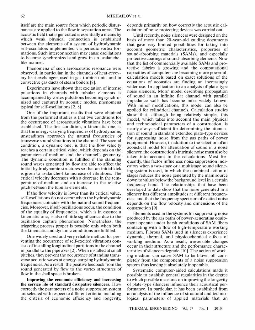
The results from systematic studies of the com�bined action of the above�mentioned factors indicatethat there are considerable possibilities for improvingthe efficiency of throttling stages by appropriatelydesigning a multistage device. An analysis of vortexattenuation of sound leads to the conclusion that it isadvisable to successively reduce the pressure dropsbeing relieved and, accordingly, flow velocities in thestages along the flow. In some cases, a positive effectcan be obtained from increasing the size of jets in thestages located upstream of the flow in terms of shiftingthe energy�carrying frequencies of generated noisetoward the low�frequency domain, thus making it pos�sible to obtain considerably better attenuation ofnoise. As an example, Figure 2 shows the calculatedacoustical indicators of a few versions of a three�stagedevice. This figure shows the values ΔLeA of soundpower radiated in the frequency band A related to theintegral noise generated by an equivalent single jet thatrelieves the entire pressure difference across the throt�tling unit. For comparison, the same figure shows thehorizontal line that corresponds to the case of minimalgeneration of sound energy in a three�stage throttlingunit, i.e., in the case of equal relative pressure drops inthrottling stages and with the minimum allowablediameters (10 mm) of throttling holes.
Since the manufacture of multistage throttlingdevices with many screens is very labor�consuming,there is a tendency of replacing them by continuous�throttling devices made in the form of channels filledwith coarse�grained or reticular elements.
–6
–8
–10
–12
–14
–160.80.60.40.20
ΔLeA, dB
π2
1
23
4
5
Fig. 2. Sound power radiated by the three�stage throttlingunit at the optimal pressure difference across the thirdstage vs. the relative pressure difference π2 relieved by thesecond stage (the holes in the first stage are 50 mm andthose in the third stage 10 mm in diameter, and the relativepressure difference across the throttling unit is 1 : 100).The diameter of holes in the second stage, mm: (1) 10,(2) 14, (3) 28, and (4) 49. Curve (5) corresponds to theminimal generation of sound energy in the three�stagethrottling unit.
66
THERMAL ENGINEERING Vol. 57 No. 1 2010
MIKHAILOV et al.
One of the main objectives that have to be achievedin designing such a device is to obtain rational distri�bution of velocities along the flow. The results from ananalysis of the multistage device presented above showthat an efficient continuous throttling device shouldbe designed so that the average flow velocity does notincrease downstream along the flow.
The dependence of flow velocity on the profile of apath filled with coarse�grained medium was deter�mined by analyzing steady one�dimensional flow in achannel with variable cross�sectional area and withfiller placed in it. According to [14], it was assumedthat the drag depends quadratically on the velocity.The flow is assumed to be adiabatic; therefore, it canbe considered with sufficient accuracy the tempera�ture in the flow is constant, because the M numbercalculated from the average flow velocity cannot bemore than 0.5–0.6. In this case, the relation betweenthe geometric parameters of the channel and the valueof M in its arbitrary cross�section can be representedby the following general expression:
where Π = pin/pout is the relative pressure drop acrossthe entire bed, pin and pout are the pressures at the bed
inlet and outlet, σ(h) = is a parameter deter�
mined by the pattern in which the cross section’s rela�tive area s = S/Sin is distributed along the currentdimensionless coordinate h = H/H0 of the channel (itcan be considered as the drag coefficient of the chan�nel part from the cross section h to the outlet cross�section), S is the current cross�sectional area, Sin is theinlet cross�sectional area, H0 and H are the channel’s
total length and its current value, σ0 = σ(h = 0), isthe channel’s total length to the characteristic grainsize ratio, and ζ is the continual drag coefficient of thegranular bed (it can be found experimentally or calcu�lated from the appropriate relations [12, 14]).
Using this expression, it is not difficult to obtainsimple solutions for channels having concrete shapes[12], based on which it is possible to construct contin�uous throttling paths the use of which will make it pos�sible to obtain the required distribution of velocitiesfor the specified difference of relieved pressure.
Considerable experience has now been gained withapplication of silencers for suppressing noise gener�ated by steam and gas discharges designed in accor�dance with the configuration developed at TsKTI,which includes two main working assemblies: a throt�tling unit and a noise absorption stage [12]. The throt�tling device serves to perform small�scale low�velocityreduction of steam pressure downstream of the steamdump valve, due to which a reduced level of the total
M h( )1
ζH0
�����������1s�� 1
σ h( )σ0
Π2 1–
������������+
�������������������������������,=
hd
s2 h( )����������
h
1
∫
H0
generated noise is obtained; in addition, this devicehas certain sound–insulating properties. The sound�absorbing elements placed downstream along the flowmake it possible to reduce noise parameters to therequired values.
One of the distinctive features of the silencersdeveloped in accordance with the TsKTI scheme isthat multistage throttling devices with drilled�holescreens are used in them without the need of introduc�ing filled or reticular elements, a solution due to whichany dependence of the flowrate and acoustic charac�teristics on the assembling technology is excluded; inaddition, these characteristics remain stable in thecourse of silencer operation. The sound�absorbingstage is formed by rectilinear channels with predomi�nantly annular cross�section that are confined bysound�absorbing lining.
A few hundred silencers were manufactured atOAO Kirovskii Zavod (Kirov Machinery ConstructionWorks) in accordance with the theoretical develop�ments carried out at OAO NPO TsKTI. Since 2003,these devices have successfully been used in theexhaust vents of OAO Gazprom’s gas turbine compres�sor stations. Apparatuses for suppressing noise gener�ated by steam dump devices were supplied to Mosen�ergo’s TETs�9 cogeneration station, and silencers forOAO Lukoil Petroleum Company were supplied in thesame period of time. There are prospects for usingsilencers constructed in accordance with the above�mentioned basic concept for suppressing noise gener�ated by antisurge control devices used in gas�turbinepower installations.
The designs of the developed silencers cover a con�siderable range of steam dump parameters (flowratesfrom 0.3 to 70 kg/s and initial pressures up to 10 MPa);the dimensions of the silencers for these conditionsvary from 500 to 2200 mm in diameter and from 850 to4500 mm in height.
The acoustical efficiency of the operating silencersfor suppressing noise generated by discharges of high�pressure steam and gas that were manufactured inaccordance with the basic concept developed at TsKTIis as high as 45–50 dB.
REFERENCES
1. N. I. Ivanov, Engineering Acoustics. Theory and Practiceof Noise Control (Universitetskaya Kniga, Logos, Mos�cow 2008) [in Russian].
2. E. B. Kudashev and L. R. Yablonik, Turbulent Near�Wall Pulsations of Pressure in the Context of ProblemsRelated to Control of Aerodynamic Noise (Nauchnyi Mir,Moscow, 2007) [in Russian].
3. V. B. Tupov, Reduction of Noise Produced by Power�Gen�erating Equipment (MEI, Moscow, 2005) [in Russian].
4. L. Cremer, M. Heckl, and B. A. Petersson, Structure�Born�Sound (Springer–Verlag, Berlin–Heidelberg,2005).
THERMAL ENGINEERING Vol. 57 No. 1 2010
THE DEVELOPMENT OF TECHNOLOGIES AND DEVICES FOR PROTECTION 67
5. F. P. Mechel, Formulas of Acoustics (Springer, Berlin–Heidelberg, 2004).
6. A. L. Terekhov, Studies of Noise and Measures forReducing It at Compressor Stations of Trunk Gas Pipe�lines (IRTsS OAO Gazprom, Moscow, 2002) [in Rus�sian].
7. L. R. Yablonik, “Development of Technologies andMeans for Protection from Noise Produced by the GasPaths of Power Installations,” Bezopasn. Zhizned.,No. 6, 12–18 (2003).
8. L. R. Yablonik, “Aeroacoustic Processes in the Convec�tive Gas Paths of Steam Boilers,” in Trudy AOOT NPOThKTI, issue 281, 1997, Vol. 2, pp. 169–177.
9. L. R. Yablonik, “Noise Suppression in Gas�TurbineUnits and Combined�Cycle Plants. Optimization andCalculations,” in Trudy OAO NPO TsKTI, issue 292,2003, pp. 78–90.
10. V. I. Murin, O. N. Emel’yanov, A. L. Terekhov, andL. R. Yablonik, “Improving the Longevity of NoiseSuppression Elements Used in Gas�CompressorUnits,” Gazovaya Promyshl., No. 2, 17–21 (2002).
11. L. A. Knomenok, V. E. Mikhailov, V. V. Sherapov, et al.,“Air�Intake Paths for Large�Capacity Gas�TurbinePower Units,” Gazoturb. Tekhnol., No. 9, 10–14(2007).
12. L. R. Yablonik, “Design of Devices for SuppressingNoise Produced by Steam Discharge,” in Trudy OAONPO TsKTI, issue 287, 2002, pp. 144–154.
13. O. N. Emel’yanov, A. L. Terekhov, and L. R. Yablonik,“Reduction of Noise Produced by Gas Discharge Sys�tems at Gas�Turbine Compressor Stations,” Nauka iTekhn. v Gazovoi Promyshl., No. 4 (24), 20–23 (2005).
14. M. A. Gol’dshtick, Transfer Processes in a Granular Bed(Inst. Teplofiz., Sib. Otd., Akad. Nauk SSSR, Novosi�birsk, 1984) [in Russian].