the cb whip ham j antenna - ham radiohamuniverse.com/n6jsxcb-j.pdf · the "j" is the best...
TRANSCRIPT
Page 1 of 10 © Copyright 2012, N6JSX Sidney, OH
All rights reserved – only non-profits may copy or reprint.
The CB whip HAM "J" Antenna by N6JSX June, 2012
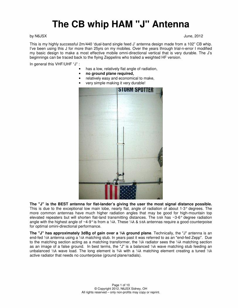
This is my highly successful 2m/440 ‘dual-band single feed J’ antenna design made from a 102” CB whip. I’ve been using this J for more than 25yrs on my mobiles. Over the years through trial-n-error I modified my basic design to make a most effective mobile omni-directional vertical that is very durable. The J’s beginnings can be traced back to the flying Zeppelins who trailed a weighted HF version.
In general this VHF/UHF “J” :
• has a low, relatively flat angle of radiation,
• no ground plane required,
• relatively easy and economical to make,
• very simple making it very durable!
The "J" is the BEST antenna for flat-lander’s giving the user the most signal distance possible. This is due to the exceptional low main lobe, nearly flat, angle of radiation of about 1-3° degrees. The more common antennas have much higher radiation angles that may be good for high-mountain top elevated repeaters but will shorten flat-land transmitting distances. The 5/8λ has ~3-6° degree radiation angle with the highest angle of ~4-9° is from a ¼λ. These ¼λ & 5/8λ antennas require a good counterpoise for optimal omini-directional performance.
The "J" has approximately 3dBg of gain over a ¼λ ground plane. Technically, the "J" antenna is an end-fed ½λ antenna using a ¼λ matching stub. In years past it was referred to as an "end-fed Zepp". Due to the matching section acting as a matching transformer, the ½λ radiator sees the ¼λ matching section as an image of a false ground. In best terms, the "J" is a balanced ¼λ wave matching stub feeding an unbalanced ½λ wave load. The long element is ¾λ with a ¼λ matching element creating a tuned ½λ active radiator that needs no counterpoise (ground plane/radials).
Page 2 of 10 © Copyright 2012, N6JSX Sidney, OH
All rights reserved – only non-profits may copy or reprint.
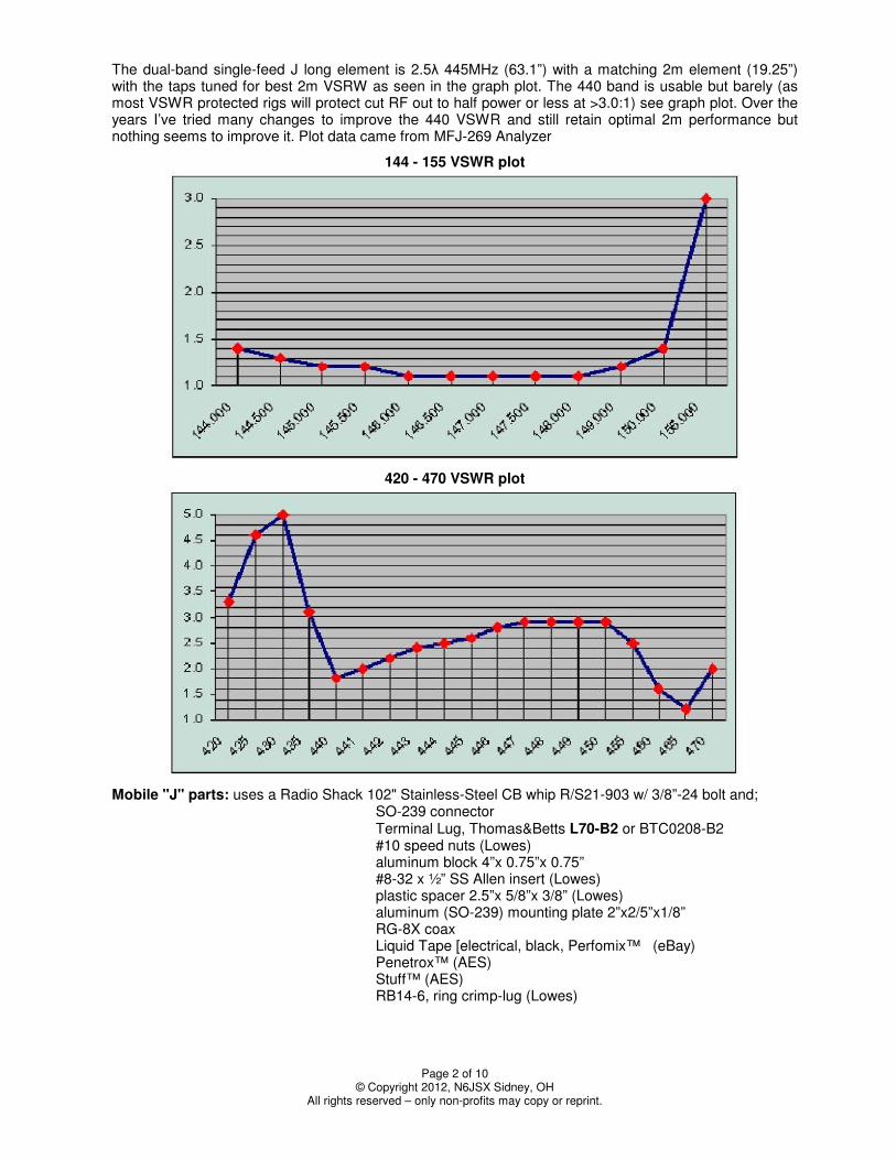
The dual-band single-feed J long element is 2.5λ 445MHz (63.1”) with a matching 2m element (19.25”) with the taps tuned for best 2m VSRW as seen in the graph plot. The 440 band is usable but barely (as most VSWR protected rigs will protect cut RF out to half power or less at >3.0:1) see graph plot. Over the years I’ve tried many changes to improve the 440 VSWR and still retain optimal 2m performance but nothing seems to improve it. Plot data came from MFJ-269 Analyzer
144 - 155 VSWR plot
420 - 470 VSWR plot
Mobile "J" parts: uses a Radio Shack 102" Stainless-Steel CB whip R/S21-903 w/ 3/8”-24 bolt and; SO-239 connector Terminal Lug, Thomas&Betts L70-B2 or BTC0208-B2 #10 speed nuts (Lowes) aluminum block 4”x 0.75”x 0.75” #8-32 x ½” SS Allen insert (Lowes) plastic spacer 2.5”x 5/8”x 3/8” (Lowes) aluminum (SO-239) mounting plate 2”x2/5”x1/8” RG-8X coax Liquid Tape [electrical, black, Perfomix™ (eBay) Penetrox™ (AES) Stuff™ (AES) RB14-6, ring crimp-lug (Lowes)
Page 3 of 10 © Copyright 2012, N6JSX Sidney, OH
All rights reserved – only non-profits may copy or reprint.
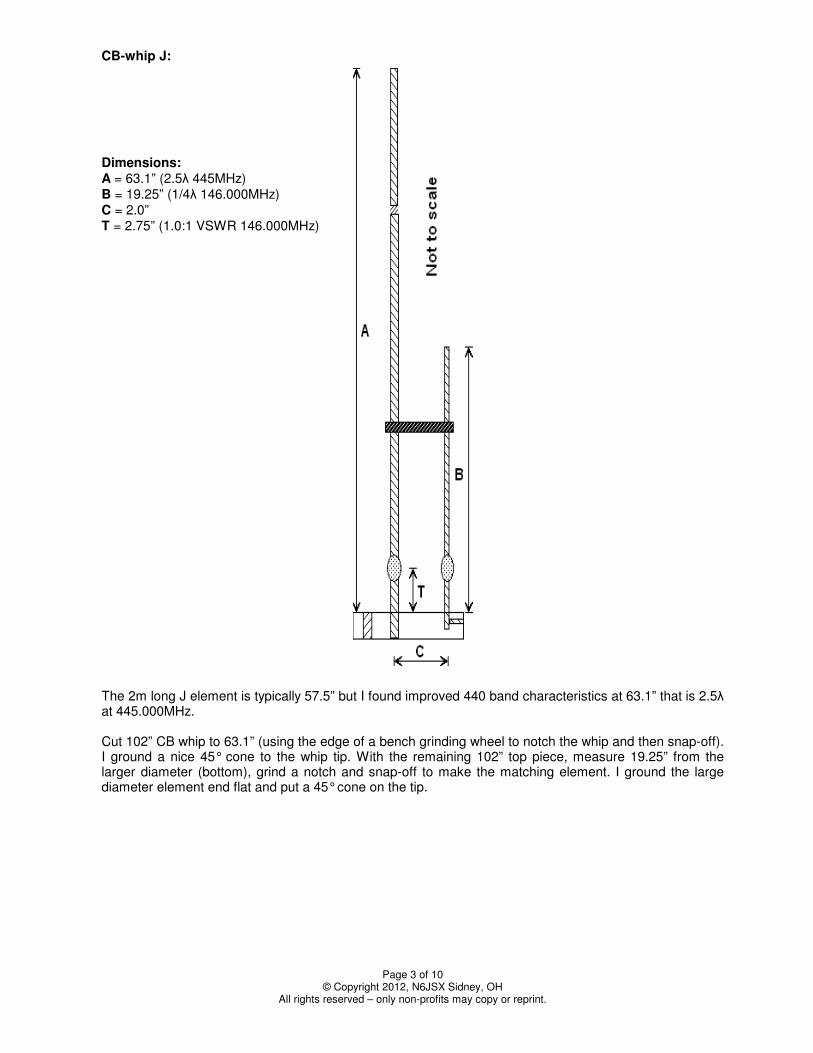
CB-whip J: Dimensions: A = 63.1” (2.5λ 445MHz) B = 19.25” (1/4λ 146.000MHz) C = 2.0” T = 2.75” (1.0:1 VSWR 146.000MHz) The 2m long J element is typically 57.5” but I found improved 440 band characteristics at 63.1” that is 2.5λ at 445.000MHz. Cut 102” CB whip to 63.1” (using the edge of a bench grinding wheel to notch the whip and then snap-off). I ground a nice 45° cone to the whip tip. With the remaining 102” top piece, measure 19.25” from the larger diameter (bottom), grind a notch and snap-off to make the matching element. I ground the large diameter element end flat and put a 45° cone on the tip.
Page 4 of 10 © Copyright 2012, N6JSX Sidney, OH
All rights reserved – only non-profits may copy or reprint.
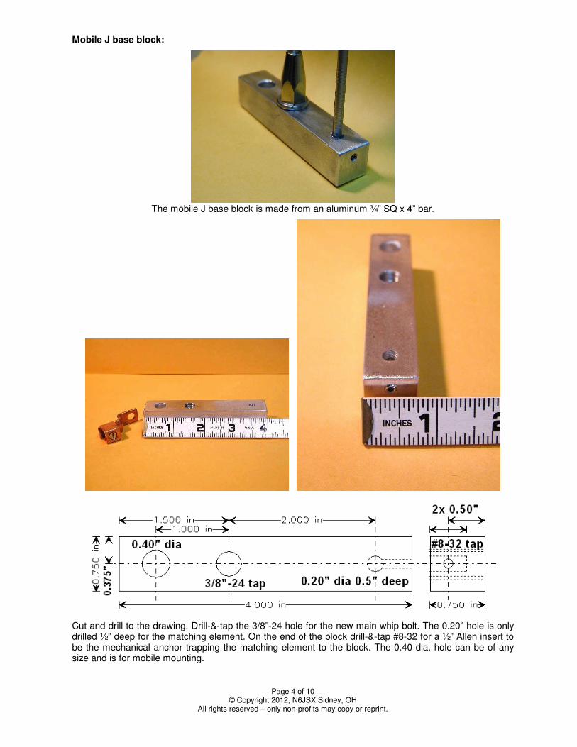
Mobile J base block:
The mobile J base block is made from an aluminum ¾” SQ x 4” bar.
Cut and drill to the drawing. Drill-&-tap the 3/8”-24 hole for the new main whip bolt. The 0.20” hole is only drilled ½” deep for the matching element. On the end of the block drill-&-tap #8-32 for a ½” Allen insert to be the mechanical anchor trapping the matching element to the block. The 0.40 dia. hole can be of any size and is for mobile mounting.
Page 5 of 10 © Copyright 2012, N6JSX Sidney, OH
All rights reserved – only non-profits may copy or reprint.
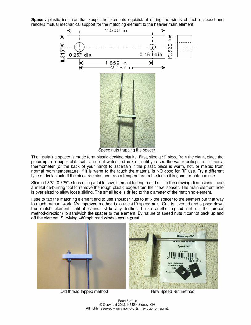
Spacer: plastic insulator that keeps the elements equidistant during the winds of mobile speed and renders mutual mechanical support for the matching element to the heavier main element:
Speed nuts trapping the spacer.
The insulating spacer is made form plastic decking planks. First, slice a ½” piece from the plank, place the piece upon a paper plate with a cup of water and nuke it until you see the water boiling. Use either a thermometer (or the back of your hand) to ascertain if the plastic piece is warm, hot, or melted from normal room temperature. If it is warm to the touch the material is NO good for RF use. Try a different type of deck plank. If the piece remains near room temperature to the touch it is good for antenna use.
Slice off 3/8” (0.625”) strips using a table saw, then cut to length and drill to the drawing dimensions. I use a metal de-burring tool to remove the rough plastic edges from the "new" spacer. The main element hole is over-sized to allow loose sliding. The small hole is drilled to the diameter of the matching element.
I use to tap the matching element end to use shoulder nuts to affix the spacer to the element but that way to much manual work. My improved method is to use #10 speed nuts. One is inverted and slipped down the match element until it cannot slide any further. I use another speed nut (in the proper method/direction) to sandwich the spacer to the element. By nature of speed nuts it cannot back up and off the element. Surviving +80mph road winds - works great!
Old thread tapped method New Speed Nut method
Page 6 of 10 © Copyright 2012, N6JSX Sidney, OH
All rights reserved – only non-profits may copy or reprint.
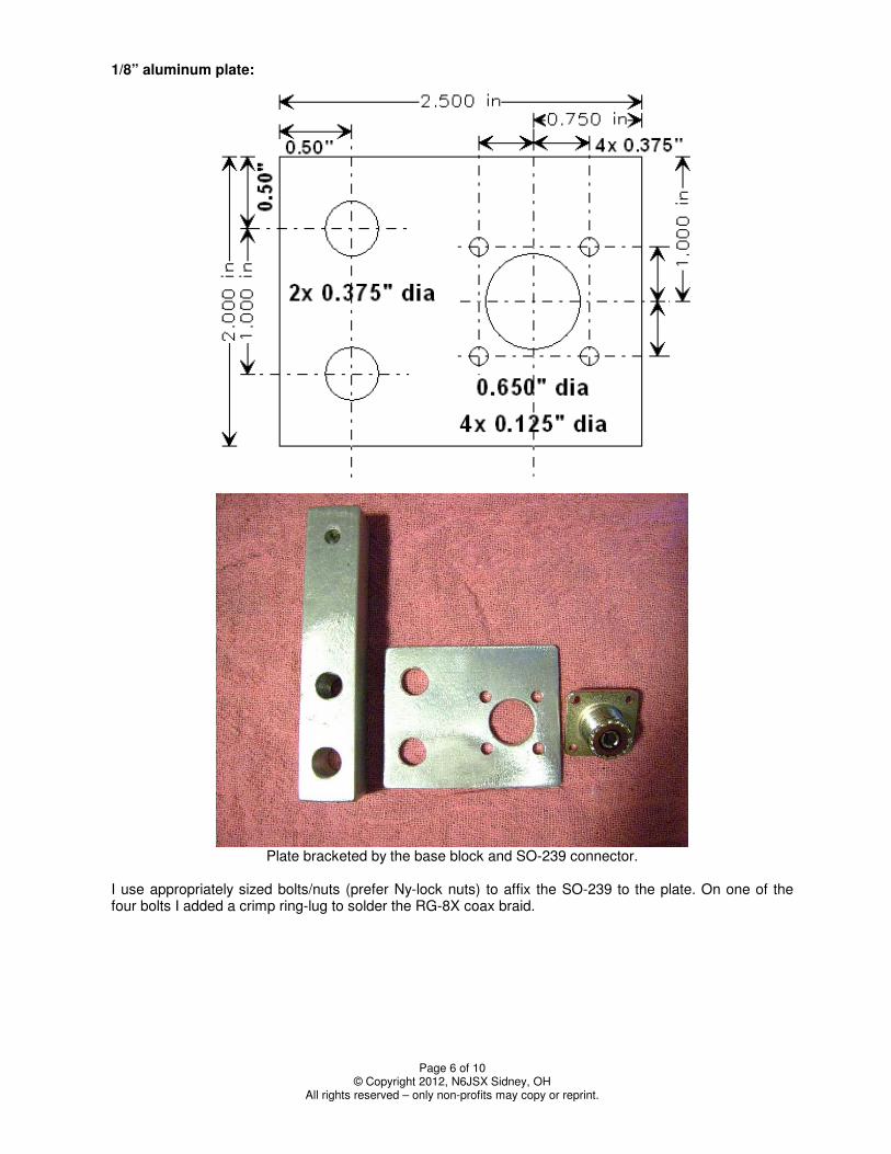
1/8” aluminum plate:
Plate bracketed by the base block and SO-239 connector.
I use appropriately sized bolts/nuts (prefer Ny-lock nuts) to affix the SO-239 to the plate. On one of the four bolts I added a crimp ring-lug to solder the RG-8X coax braid.
Page 7 of 10 © Copyright 2012, N6JSX Sidney, OH
All rights reserved – only non-profits may copy or reprint.
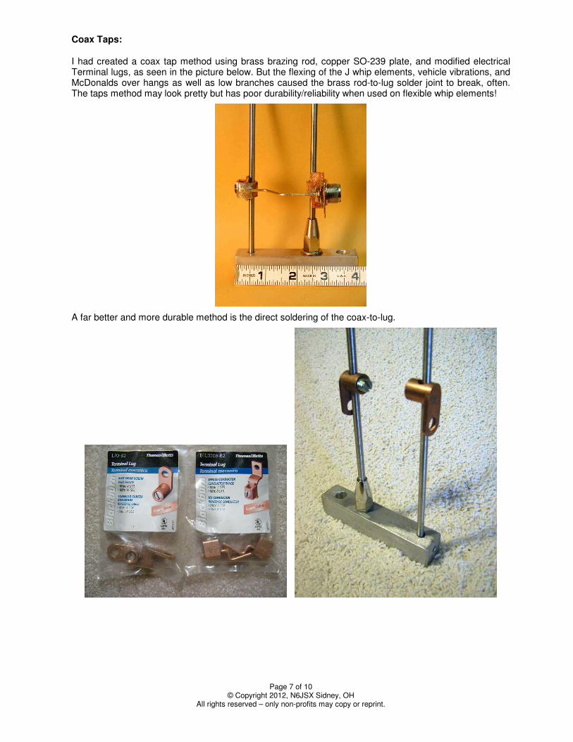
Coax Taps: I had created a coax tap method using brass brazing rod, copper SO-239 plate, and modified electrical Terminal lugs, as seen in the picture below. But the flexing of the J whip elements, vehicle vibrations, and McDonalds over hangs as well as low branches caused the brass rod-to-lug solder joint to break, often. The taps method may look pretty but has poor durability/reliability when used on flexible whip elements!
A far better and more durable method is the direct soldering of the coax-to-lug.
Page 8 of 10 © Copyright 2012, N6JSX Sidney, OH
All rights reserved – only non-profits may copy or reprint.
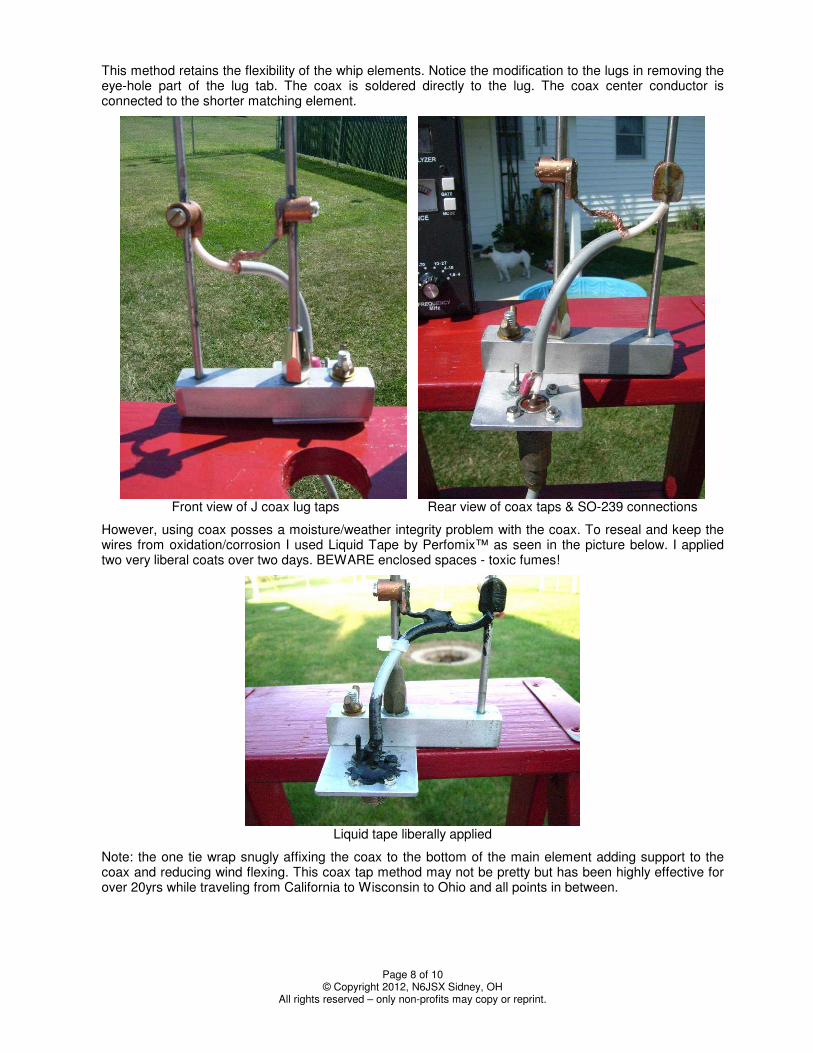
This method retains the flexibility of the whip elements. Notice the modification to the lugs in removing the eye-hole part of the lug tab. The coax is soldered directly to the lug. The coax center conductor is connected to the shorter matching element.
Front view of J coax lug taps Rear view of coax taps & SO-239 connections
However, using coax posses a moisture/weather integrity problem with the coax. To reseal and keep the wires from oxidation/corrosion I used Liquid Tape by Perfomix™ as seen in the picture below. I applied two very liberal coats over two days. BEWARE enclosed spaces - toxic fumes!
Liquid tape liberally applied
Note: the one tie wrap snugly affixing the coax to the bottom of the main element adding support to the coax and reducing wind flexing. This coax tap method may not be pretty but has been highly effective for over 20yrs while traveling from California to Wisconsin to Ohio and all points in between.
Page 9 of 10 © Copyright 2012, N6JSX Sidney, OH
All rights reserved – only non-profits may copy or reprint.
Tuning: Before you set all the bolts/nuts and apply liquid tape you need to tune the J for optimal performance. I highly recommend you very liberally apply Penetrox™ to ALL and EACH metal-to metal joint surface and screw threads. I have found in my +40yrs of HAM’ing that antenna metal joints/clamps/threads will eventually corrode to the point of locking threads into the metal especially with aluminum/copper and stainless-steel hardware. Penetrox™ a conductive gray grease inhibits metal-to-metal moisture corrosion/oxidation.
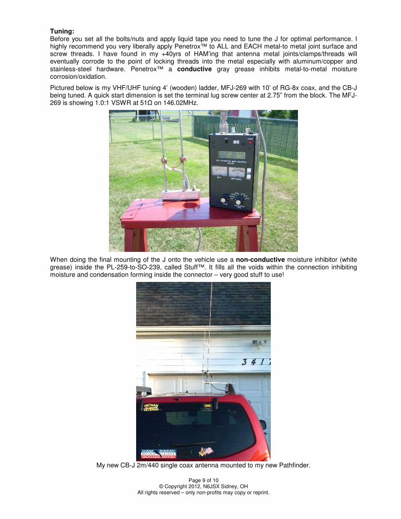
Pictured below is my VHF/UHF tuning 4’ (wooden) ladder, MFJ-269 with 10’ of RG-8x coax, and the CB-J being tuned. A quick start dimension is set the terminal lug screw center at 2.75” from the block. The MFJ-269 is showing 1.0:1 VSWR at 51Ω on 146.02MHz.
When doing the final mounting of the J onto the vehicle use a non-conductive moisture inhibitor (white grease) inside the PL-259-to-SO-239, called Stuff™. It fills all the voids within the connection inhibiting moisture and condensation forming inside the connector – very good stuff to use!
My new CB-J 2m/440 single coax antenna mounted to my new Pathfinder.

Page 10 of 10 © Copyright 2012, N6JSX Sidney, OH
All rights reserved – only non-profits may copy or reprint.
Writer BIO: Dale Kubichek, BS/MS-EET, GROL/RADAR, N6JSX - Amateur Extra; first licensed in 1972. Served 10yrs USN, Vietnam Vet, FTG1 Gun/Missile systems & electronics instructor. Electronics Test/MFG/QA Engineer & Program Manager, in; aerospace - Hughes, Northrop, Rockwell, HawkerBeechcraft; commercial - Magellan, Mitsubishi, Emerson-Copeland; heavy construction - TEREX, Manitowoc Cranes, Magnetek; communications – Hughes, STM, RockwellCollins. Currently, a USAF SPO Sr. Engineer on UAV SIMs. Interests are in designing/testing antennas, RDF hunting/training, SAT OPs; published numerous articles in 73 Magazine, eHAM.net, WI Badger Smoke Signals, HamUniverse.com. Owner of: http://groups.yahoo.com/group/HAM-SATs ,
http://groups.yahoo.com/group/RDF-USA , and many more.