the calculus of scale - asprs · the calculus- of scale*. ... and made either easy assumptions re...
TRANSCRIPT
THE CALCULUS OF SCALE*- .
A mrom H. Katz, Chief Physicist, Res'earch Studies Office, PhotoReconnaissance Lab, Wright Air Development Center,
Wright-Patterson Air Force Base, Dayton, Ohio
ABSTRACT
The limitations to the now prevalent arithmetic notions of scale as a constant and afraction are discussed and are shown to arise from the fictitious vertical photograph. Analternative proposal is made for the use of "scale numbers" which have analytic properties and which yield insight into the role of scale, especially in obliques. '
Four specific aerial photographic problems are analyzed. These deal with the problem of getting the range at which air-ground guns or rockets are fired, the problem ofgetting accurate scale over unknown territory and without barometric altimeter correction, and the problems of determining altitude·and depression angle in forward obliquephotography made in level flight and in a dive.
In all these problems, use is made of scale as a changing parameter; and the usefulness of this approach to these and other problems is demonstrated:
CONTENTS
PageI. Introduction......................................................... 63
II. The Concept of Scale and Its Use. . . . . . . . . . . . . . . . . . . . . . . . . . . . . . . . . . . . .. 64 ,III. Ground Measurements without Altitude or Ground Data. . . . . . . . . . . . . . . . .. 67
Problem One: Estimating the Range of Air-Ground Gun or Rocket Fire.. . .. 67Problem Two: Accurate Altitude Determination in Vertical Photography by
a Method of Differences. . . . . . . . . . . . . . . . . . . . . . . . . . . . . . . . . . . . . . . . . . . .. 68Problem Three: Altitude, Camera Depression Angle, and Scale Determination
from Forward Oblique Photography. . . . . . . . . . . . . . . . . . . . . . . . . . . . . . . . .. 70Problem Four: Altitude, Dive Angle, and Scale Determination from Forward
Oblique Photography Secured in a Dive. .. . . . . . . . . . . . . . . . . . . . . . . . . . . .. 75IV. Conclusion and Acknowledgment. . . . . . . . . . . . . . . . . . . . . . . . . . . . . . . . . . . . . .. 78
I. INTRODUCTION
T HIS paper consists of two unequal parts. The first part deals with the concept of scale; the second with a series of (it is hoped) practical and u&eful
problems.The second part of this paper was actually started in connection with the
author's work on determination of sea-wall heights for the Inch'on invasion(Reference 1). The origin of this problem was summarized in that paper, fromwhic'h the following section is reprinted:t
"The description of the analysis used in this problem rightly emphasizes that our basicdata (ground distances on the vertical photos, Figures 4 and 5), were derived through useof a 1: 12,500 map of Inch'on. Perhaps we could have used high-altitude photographsand made either easy assumptions re verticality or tedious corrections to verticality.There was neither virtue nor time enough for this procedure. Low-altitude' barometricaltimeter errors in jet aircraft are too large for even rough photogrammetric procedures.
"It became obvious that w'hat was needed (for future problems) was a method ofmaking ground measurements which would be completely independent of both any(prior-known) ground data and of altitude.
"This sounds like a tough specification. Actually itis both fairly si111ple and fairly
* Paper read at Eighteenth Annual Meeting of the Society, Hotel Shoreham, Washington,D. C., January 9 to 11, 1952.
t This quotation is from Reference 1, 'pp. 97-98.
63
64 PHOTOGRAMMETRJC ENGINEERING
obvious. A verbal argument will illustrate the system which the author conceived afterthe main problem was solved..
"Suppose we have a camera mounted at 0° depression angle with respect to thelongitudinal axis of the aircraft (i.e., a bore-sighted ,camera). Suppose flying either atvery low altitude (or in a dive), an object of lateral dimension x is photographed at acertain time t. If at a known interval later the same object is photographed': then theratio of image sizes is a direct function of the distances away from the object. The trickis to get the difference in the two distances without knowing either distance. This canbe done if we know both true ground speed and the exact interval between photographs.Knowing this (readily available) information will enable calculations of the true size of .the ground object. Putting the same argument in another way, the rate of change ofSx, dSx/dt, is a simple function of the distance from the target. We can obtain dSx/dtfrom two successive photographs taken at times which are not necessarily close, andeasily make the required ground measurements."
n. THE CONCEPT OF SCALE AND ITS USE
Scale-as it is used almost universally-refers to the ratio of photographicimage size (or map dimension) to the size of the original ground object. Thenumbers used are always give'n as, say 1: 5,000, or 1 :40,000-which is read as"one to five thousand or one to forty thousand." That this usage is well nighuniversal and traditional does not insure that it is either good or useful. In fact,the author believes that this usage is neither good nor useful.
Within the author's experience, and that of numerous photogrammetrists,aerial photographers, and photo-interpreters, to whom he has talked, the soleuse of "scale" has been to go from the map or photograph (the image) to the corresponding ground dimension. Thus a small number (image) is multiplied by alarge number to get the ground distance. This multiplier is obviously the reciprocal of the number defined above as scale.
In an earlier paper (Reference 2), scale numbers Si were defined so that animage measurement multiplied by the appropriate scale number yields the corresponding ground measurement. The scale numbers used in that paper wereSv, S"" Sy, Sk, SA for the truly vertical photograph, for x and y directions in tveoblique photograph, for height, and for area, respectively.
The important point is that these scale numbers Si are the ones that are actually used by everyone; thus the definition is an operational one. In Reference 1this point is discussed as follows (p. 83):
"The scale of Figures 4 and 5 was thus determined to be 1:3,270 and 1:3,290. (Thisis conventional representation of scale. The author much prefers to use vertical scalenumbers Sv, which would be 3,270 and 3,290. These numbers are easier to write and touse, for their definition is an operational one. The major use to which a map is put is tocalculate ground distances. Therefore Sv is defined as the number by which a map distance is multiplied to get a ground distance. This usage does away with the confusionalways present when discussing "large-scale," "small-scale," etc.)"
This matter of operational definitions is very important, and the particularexample herein treated is simple; for a comprehensive discussion on operationalconcepts and definitions, the reader is referred to Nobel Prize-Winner P. W.Bridgman's, "The Logic of Modern Physics" (Reference 3), wherein, amongother things, he says (p. 7) " ... For, of course, the true meaning of a term isto be found by observing what a man does with it, not what he says aboutit.... tt ....
Some may feel that this point has been labored or bdabored more thanenough. This is not so. In the next paragraphs we shall see that the concept of
THE CALCULUS OF SCALE 65
scale as a fraction, and other pernicious notions, have had a stultifying effecton photogrammetric analysis.
Let us now examine another underlying tradition entering into the natureand use of scale.
The arithmetic concept of scale-derived from consideration of the verticalphotograph-is a convenient fiction. It would indeed be a lovely (photogrammetric) world if all aerial photographs were truly vertical, thus yielding a constant scale number in all directions on the photographs. However, the trulyvertical photograph (meaning that the lens axis was perpendicular to the surface of the earth immediately below the aircraft, and that this axis is also perpendicular to the film plane) is a rare event, even when such photography is attempted. The vast body of photogrammetric literature, techniques, and equipment designed to deal with tilt is ample testimony to the rarity of the verticalphotograph.
Thus the vertical photograph is but a very special case of the oblique photograph. When the aerial photograph is not even a near-vertical, it is even moreobvious that the arithmetic concept of uniform and constant scale----:-so handyfor a vertical-is of no avail.
In the oblique photograph the scale numbers are constantly changing, andat any given point the scale numbers are (in general) different in all directions.This point is even more obvious when examining a map covering a good fractionof the world. In conformal maps, the scale is the same in all directions at anypoint, but varies continuously from point to point. In other types of maps, thescale is different in different directions at any point. Were one to build a theoryof scale (and photogrammetry) starting with the oblique photograph, it is clearthat scale (or preferably "scale numbers") must necessarily be represented by acontinuous point function. These expressions must clearly be differential equations.
An earlier paper by the author (Reference 2) could well have been subtitled,"The Differential Calculus of Scale," for in this paper, the scale numbers Si forelements of interest in an oblique photograpb were derived. These expressionswere differential eql,lations and will be repeated here.
In all these equations x and y refer to the conventional cartesian coordinatedirections when the photograph is so held that its top and bottom edges areparallel to the horizon and the foreground is at the bottom of the photograph.
The symbols used are:
H = flying heightf = focal length
X = ground distance in x directionY = ground distance in y directionh = height of an object on the groundI = image measurement (for x, y, h, this is a length)
A = ground areaa = image areacP = angle off axis, measured down from horizon() = depression angle of camera axis, measured down from the horizon
The scale numbers Sv, S", S", Sh, SA were defined above.
dX dY HS =-=-=-
• v dI dI f
66 PHOTOGRAMMETRIC ENGINEERING
1.-....dX H cos r/>
S", = -= - -----dI f sin (0 + r/»
dY H cos2 r/>Sy = -= - -----
dI f sin2 (0 + r/»
dh 2H cos2 r/>Sh=-=------
dI f sin 2(0 + r/>~
dASA = - = SxSY '
da
In both References 1 and 2 methods were developed indicating the usefulnessof these scale numbers for making small measurements from photographs, measurements which either assumed that the appropriate Si remained sensibly constant over the small interval used, or employed an approximate or average valueof the appropriate Si over larger areas on the photograph. It is clear that themore or less orthodox and cumbersome geometric analysis of the oblique photograph could solve these problems only with cumbersome, stiff, inelegant machinery. Most important, the insight into what is really happening in anoblique photograph is either lost or is very difficult to achieve. Examination ofthe effects of small changes in angle of depression, in small excursions over theimage- plane,-these are practically impossible to evaluate by ordinary geometric and arithmetic analysis.
Scale is a changing function; it can best be handled by the differential andintegral calculus. Photogrammetric analysis has, by and large, and with onlyinfrequent exceptions, ignored the potentialities and power of the analytic ap':proach.
There remains to be developed the integral calculus of scale-wherein anyground measurement, especially over large distances and areas on the photograph, can be made. One can at least write the expressions for which simple andpracticable working systems must be developed. Sample expressions are:
For Y distances: .
For areas:
f "'2fY2A = S xSydydx.
%1 111
As an example of the power of the analytic approach and the comparativesterility of the orthodox geometric analysis, the author cannot refrain frommentioning that in discussions with some few photogrammetrists, they failedcompletely to understand what is meant by "scale at a point" or "two scales(x and y) at a point in an oblique photo." These concepts are of course elementary, and differ not one whit from the most elementary concept in the differential calculus, that of slope at a point.
It is not claimed that these notions solve all problems, for even in Reference1, the author ignored more topics than were then treated. It is a beginning,however, and it is hoped that other workers will continue from this modest beginning.
THE CALCULUS OF SCALE 67
III. GROUND MEASUREMENTS WITHOUT ALTITUDE OR GROUND DATA.
GROUND
FiG. 1
I
/ I fiGHTER/ / I DIVE~ '-.. 'H PATHH H, 1
PROBLEM ONE-ESTIMATING THE RANGE OF AIR-GROUND GUN OR ROCKET FIRE
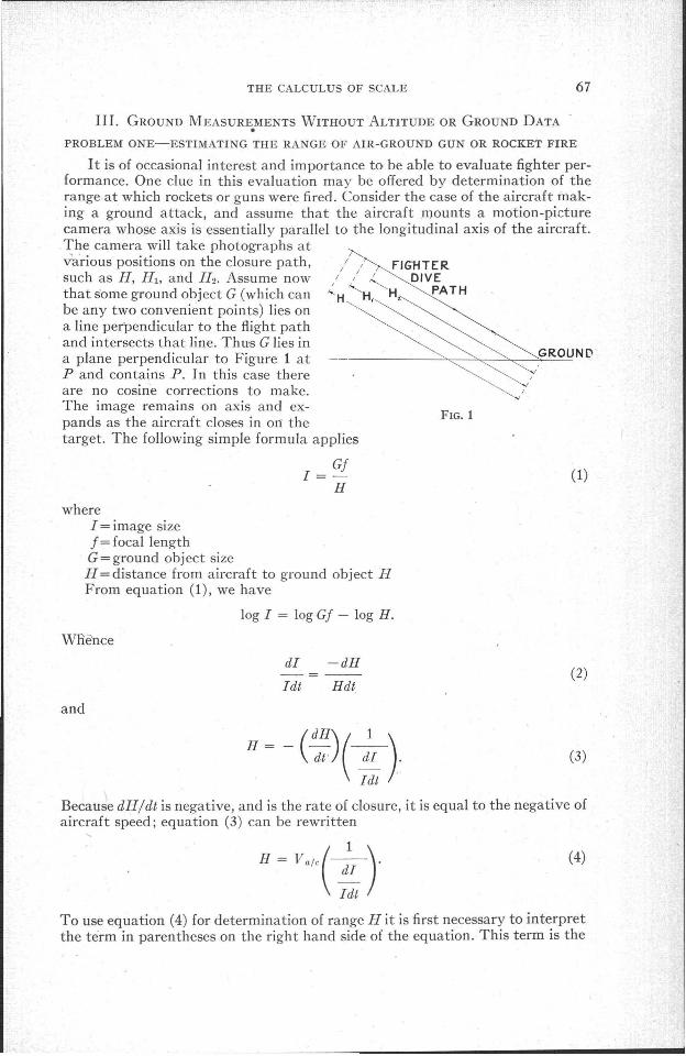
I t is of occasional interest and importance to be able to evaluate fighter performance. One clue in this evaluation may be offered by determination of therange at which rockets or guns were fired. Consider the case of the aircraft making a ground attack, and assume that the aircraft mounts a motion-picturecamera whose axis is essentially parallel to the longitudinal axis of the aircraft.The camera will take photographs atva'rious positions on the closure path,such as H, HI, and H 2• Assume nowthat some ground object G (which canbe any two convenient points) lies ona line perpendicular to the flight pathand intersects that line. Thus G lies ina plane perpendicular to Figure 1 atP and contains P. In this case thereare no cosine corrections to make.The image remains on axis and expands as the aircraft closes in ort thetarget. The following simple formula applies
Gj1=
H(1)
whereI = image sizej = focal lengthG = ground object sizeH = distance from aircraft to ground object HFrom equation (1), we have
log 1= logGj - log H.
WRence
dI -dH
Idt Hdt(2)
and
H = - (:~) ( d~ ).
Idt
(3)
Because dH/dt is negative, and is the rate of closure, it is equal to the negative ofaircraft speed; equation (3) can be rewritten
H= Va/c( :1 ).Idt
(4)
To use equation (4) for determination of range H it is first necessary to interpretthe term in parentheses on the right hand side of the equation. This term is the
68 PHOTOGRAMMETRIC ENGINEERING
(=412 mph).
reciprocal of the rate of change of image site per second. This quantity can bedetermined from successive measurements on the emotion picture film. An example will demonstrate this:
Let
Vale = 600 feet/sec.
Then at H = 2,000', we have
dI +dH 600-=--=--=0.30.I dt Hdt 2 ,000
This means that at this point (H = 2,000'), the image I is growing at the rateof 30% per second.
If frame speed is known to within X% and aircraft speed to within- Y%, itis clear that an upper limit on the accuracy of determination of the range H iscertainly (X+ Y)%, for we have not as yet estimated the accuracy of determination of dI/ldt. A rough statement of over-aU accuracy can be made, however. This method is a photo-interpretation class measurement process. It is inthe 5-10% class, giving such accuracy easily, but capable, under unusual conditions or with special equipment, of accuracies of the order of 1%. To theobvious question which may be raised "Why not put known objects on thetarget range?" the obvious answer is that we are discussing doing this undercombat conditions, which severely limit ground access for the experimenter.
Another approach for this identical problem begins with equation (1), andphotographs taken at the two positions H l and H 2• If H l is the range at whichfiring starts we have' immediately
(5)
(6)
where t is the interval between photographs. From equations (5) and (6), weobtain immediately
(1 - ~:)(7)
Thus, without knowing the size of any ground object, but from measuringthe ratio of successive images of the ground object, H is determined. The timeof firing of a gun or rocket does not necessarily (and in fact will likely not) coincide with any particular exposure; nor are gun cameras so mounted as to recordthe very first part of a trajectory. These factors mean only that care and furtherimprovisation must be taken in application of the methods given here, and inve-stigation of the accuracy of the method must be considered an integral partof the problem in each application.
PROBLEM TWO: ACCURATE ALTITUDE DETERMINATION IN VERTICAL PHOTOGRAPHY
BY A METHOD OF DIFFERENCES
The thinking on the following interesting problem will be recognized as intimately related to the preceding problem.
THE CALCULUS OF SCALE 69
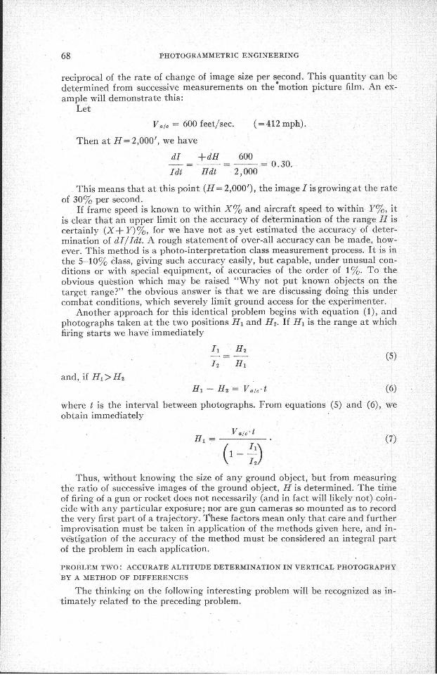
Suppose a photographic aircraft is flying at a great distance from a friendlymeteorological station, and over territory whose height above sea level is unknown (Figure 2). The aircraft carries a sensitive altimeter of the conventionaltype. Again, by a method essentially the same as in the previous problem, it ispossible to make fairly accurate scale determinations.
This solution to the problem depends on the aircraft's taking two photographs over the same ;irea at different altitudes.
Now, unless the proper sea-level pressure setting is known, absolute altitudeHI above sea level cannot be computea from the (temperature-corrected) altim-
GROUND LEVEL
SEA LEVELFIG. 2
eter reading. But this correction is in the nature of a dial rotation only, sothat the same absolute error will be made at H 2• This very fact insures that thedifference HI - H 2 can be accurately computed. Of course temperature corrections to the readings at HI and H 2 must be made, and one must be sure thatthere is no inversion between HI and H 2• At considerable altitudes, say 20,000'and higher, in photographic weather, such inversions are extremely improbable.
The solution in this case is much the same as in the preceding problem, andyields very simply that
HI - H 2HI =----- (8)
Note that in measurement of I r and 12, the selected points need not bephysically related and should be preferably some distance apart. For example,if HI is about 20,000 and H 1-H2 about 2,000', then 11112 will be 0.90.
If the two points on the print are about six or seven inches apart, the difference in image 'sizes between 12 and II, and therefore their ratio can be determined quite accurately. (It must be remembered that 1 2 and II are imagemeasurements of the same ground distance.)
There are some interesting implications and possibilities in this differencingmethod. It affords an extra parameter as it were, and may prove very usefulin related work, such as tilt analysis. Some work along this line, using some ofthese ideas, has been started by Mr. Eldon D. Sewell.
A word about the accuracy of this method. It is obviously and intimately afunction of the accuracy of the sensitive altimeter; the estimates of the Equip-
"
70 PHOTOGRAMMETRIC ENGIN~ERING
ment Laboratory altimeter experts, which the author obtained through Dr.Sam Burka, are about 1!% of altitude. It is entirely possible, and needs investigation, that a goodly portion of such error may cancel out when takingdifferences, over relativeJy small changes. But this hopeful notion has no soundbasis as yet, and must be regarded as a teasing prospect.
It is clear from a description of this method that certain aspects of practicalproblems have been ignored-tilts, relief, etc. All this means is that further developments are needed. In their aosence, this must be relegated to t,he class ofP.I. techniques, which ,are charaCterized by accuracies, real and required, ofseveral per cent.
/e
/
FIG. 3
PROBLEM THREE: ALTITUDE, CAMERA DEPRESSION ANGLE AND SCALE DETER
MINATION FROM LEVEL-FLYING FORWARD OBLIQUE PHOTOGRAPHY
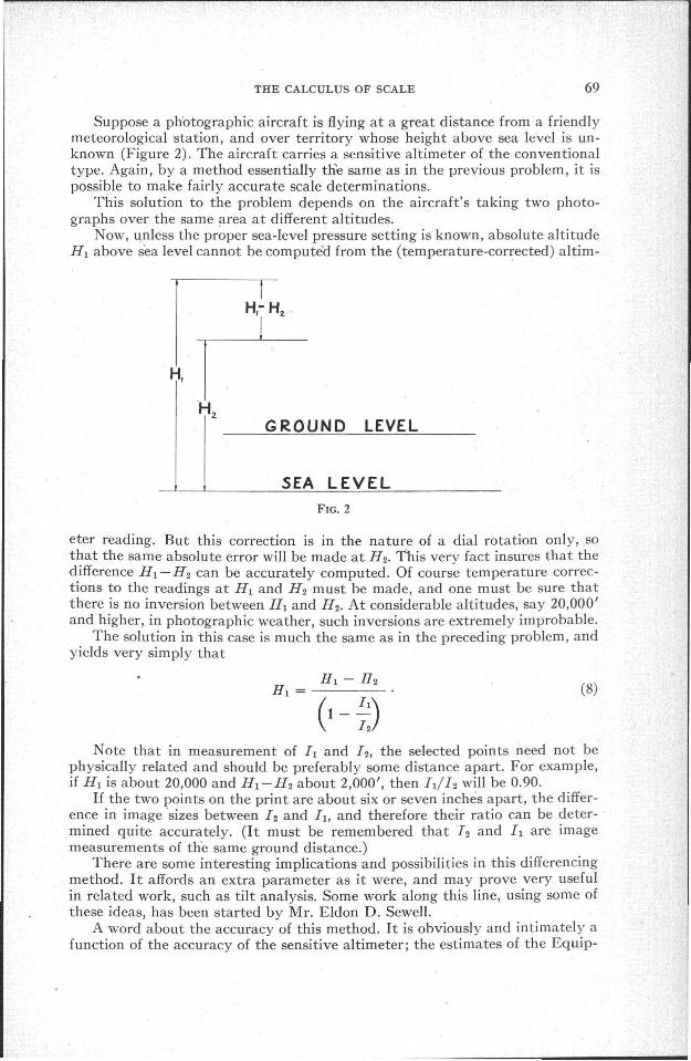
Consider now the following interesting problem. A modern high speed aircraft has installed in it a forward oblique camera. It makes a level pass over a
target area; and now we wish to determine'dimensions, distances, etc. ofground objects captured on the photography. If we can get, or knowspeed and camera interval data, thisproblem is easily solved; and as partof the" solution, the exact angle of depression of the camera is found. Trueground speed in a low flying highspeed aircraft can be obtained towithin several per cent, and if care isexercised, more accurately than this.Calibrated intervalometers, orwatches mounted in cameras andphotographed on the film can yieldthe interval between photographs to
(9)...
within a per cent or two.Reference to Figure 3 will explain the geometry of such photography.In this figure, () is the camera axis depression angle, cP1and cP2 successive
positions of the ground object G with respect to the axis as the aircraft advancesfrom A toB.' .
As before G is required to lie on a line perpendicular through G.Then if 11 is the length of the image of G when the aircraft was at A, 12 the
length of the image when the aircraft was at B, these image lengths are relatedto the actual length G by the equations
Sx!·I1 = G
SX2'[2 = G
where the Sx,'s are the x scale numbers
H cos cPiSx' = (10)
, f sin (8 + cPi)
Now using the concept of effective altitude H., which w~s defined in Reference 2as that number which, when divided by focal length, yields the appropriatescale, we have
He·Sx'=-", f (11)
THE CALCULUS OF SCALE
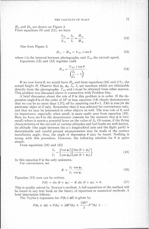
He, ana H e2 are drqwn on Figure 3.From equations (9) and (11), we have
Also from Figure 3,
H c, - H e2 = Va/c·t cos IJ
where t is the interval between photographs, and Va/ c the aircraft speed.Equations (12.) and (13) together yield
Va/c' t cos IJH e2 = ---~-
(;: - 1)
71
(12)
(13)
(14)
If we now knew 0, we would have H e2 and from equations (10) and (11), theactual height H. Observe that 1>" 1>2, 12, 1, are numbers which are obtainabledirectly from the photographs. Va/ c and t must be obtained from other sources.This problem was discussed above in connection with Problem One.
A brief discussion about the role of 0 in this problem is in order. If the depression angle 0 is of the order of 100 or less, equation (14) clearly demonstratesthat we can be no more than 1.5% off by assuming cos 0 = 1. This is true for theparticular object at G only. Remember that G was selected for convenience only,and that we may be interested in other objects as well. The true role of 0, andits importance, especially when small, is more easily seen from equation (10).Here we have sin 0 in the denominator (assume for the moment that 1> is verysmall) where it exerts a powerful lever on the value of S•. Of course, if the flyingcharacteristics of the aircraft at various altitudes and fuel loads are well known,its altitude (the angle between the alc longitudinal axis and the flight path) isdeterminable and careful ground measurements may be made of the camerainstallation angle; thus, the angle of depression 0 may be found. Nothing iswrong with this procedure. However, the following solution for 0 is quitesimple.
From equations (10) and (12)
12 = [COS cf>1] [Sin (IJ + cf>2)]. (15)1, COScf>2 sin (IJ + cf>,)
In this equation 0 is the only unknown.For convenience, set
12 COS cf>2K=---·
1, cos cf>1(16)
Equation (15) now can be written
F(IJ) = sin (IJ + cf>2) - K sin (IJ + cf>,) = O. (17)
This is readily solved by ewton's method. A full exposition of the method willbe found in any text book on the theory of equations or numerical methods. Abrief description follows:
The Taylor'.s expansion for F(Oo+6.0) is given by
(M)2F(Oo + M) = F(Oo) + "t1IJF'(IJo) + --FI/(IJo) +
2
72 PHOTOGRAMMETRIC ENGINEERING
where F' (fJo), F" (fJo) , .. are the first, second, etc. derivatives of F(fJ) evaluatedat 80•
H t::..6 is reasonably small, we may drop the higher terms; we have
F(Oo + t::..e) = F(Oo) + t::..eF'(Oo). (18)
Now let fJo be the first approximation to the root of equation (17); t::..0 is the correction sought after, so that F(fJo+fj.fJ) =0. From equation (18), setting F(80
+ fj.fJ) = 0,
t::..e=F(Oo)
---.F'(Oo)
(19)
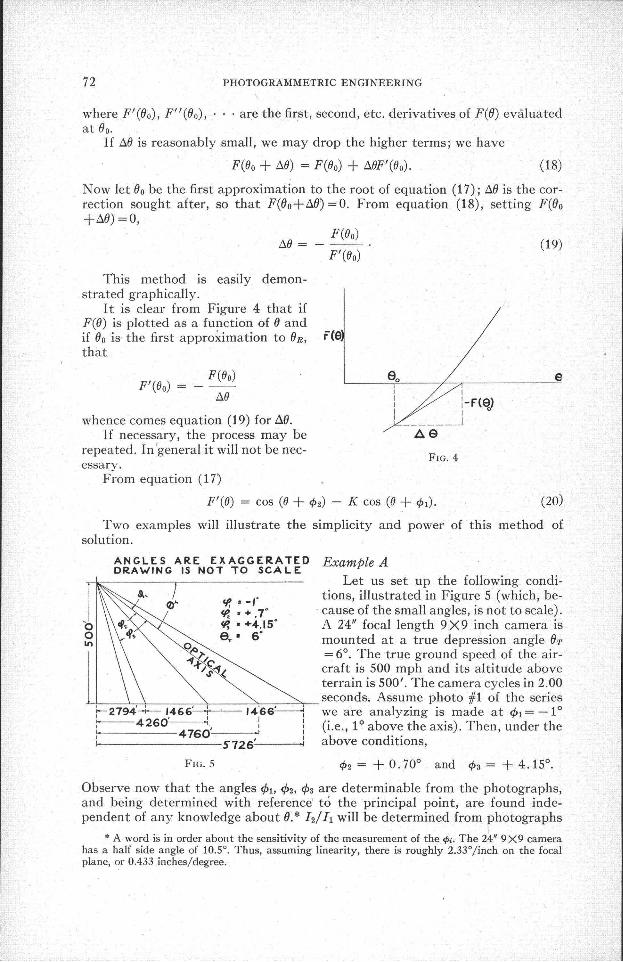
Tbis method is easily demonstrated graphically.
It is clear from Figure 4 that ifF(fJ) is plotted as a function of fJ andif fJo is the first approximation to fJ R , F(Sthat
e
(20)
FlG.4
II I
I :-F(S>I I 0
I ..-J~e
F(Oo)---
t::..oF'(Oo) =
whence comes equation (19) for AfJ.If necessary, the process may be
repeated. In 'general it will not be necessary.
From equation (17)
F'(O) = cos (0 + tP2) - K cos (0 + tPl)'
Two examples will illustrate the simplicity and power of· this method ofsolution.
ANGLES ARE EXAGGERATEDDRAWING IS NOT TO seA L E
\ .
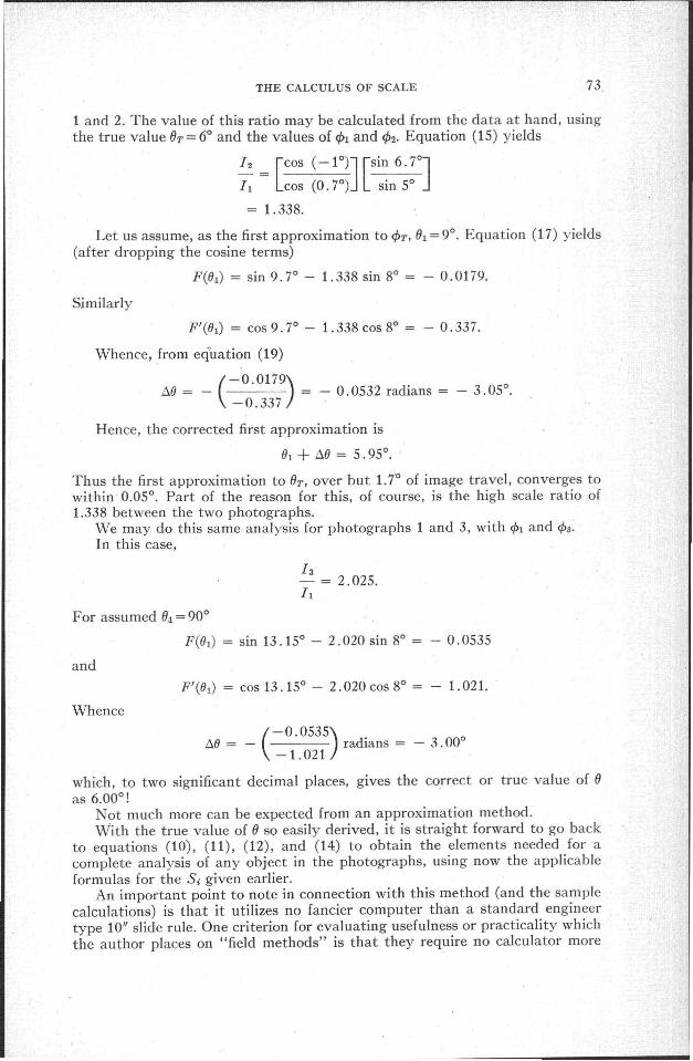
Example ALet us set up the following condi-
<P, • -r tions, illustrated in Figure 5 (which, be-tP. • + .7' cause of the small angles, is not to scale).
"0 ~ • +4.15' A 14" focal length 9 X9 inch camera iso aT' 6'In 0,0 mounted at a true depression angle fJ r
1... )o/. = 6°. The true ground speed of the air-.f/,r~, craft is 500 mph and its altitude above
terrain is 500'. The camera cycles in 2.00
r::m~:l==-i466C+==U6E;C~rseconds. Assume photo #1 of the series1--2794-+- 1466': 1466~ we are analyzing is made at cPl = -1°i---4260~. I : (i.e., 1° above the axis). Then, under the: 4760'-----<I I
I 5726': above conditions,
FlG.5 tP2 = + 0.70° and tP3 = + 4.15°.
.Observe now that the angles cPl, cP2, cP3 are determinable from the photographs,and being determined with reference' to the principal point, are found independent of any knowledge about fJ. * 12/11 will be determined from photographs
* A word is in order abollt the sensitivity of the measurement of the <Pi. The 24" 9 X9 camerahas a half side angle of 10.5°. Thus, assuming linearity, there is roughly 2.33°/inch on the focalplane, or 0.433 inches/degree.
THE CALCULUS OF SCALE 73
1 and 2. The value of this ratio may be calculated from the data at hand, usingthe true value (}T = 6° and the values of €/>1 and €/>2' Equation (15) yields
12 = [COS (-1O)J [Sin 6. 7°JII COS (0.7°) sin 5°
= 1.338.
Let us assume, as the first approximation to €/>T, fh = 9°. Equation (17) yields(after dropping the cosine terms)
F(Ol) = sin 9.7° - 1.338 sin 8° = - 0.0179.
Similarly
FI(Ol) = cos9.7° - 1.338 cos 8° = - 0.337.
Whence, from equation (19)
(-0.0179)/::,,() = - = - 0.0532 radians = - 3.05°.-0.337 .
Hence, the corrected first approximation is
01 + /::,,() = 5.95°.
Thus the first approximation to OT, over but 1. 7° of image travel, converges towithin 0.05°. Part of the reason for this, of course, is the high scale ratio of1.338 between the two photographs.
We may do this same analysis for photographs 1 and 3, with €/>l and €/>a.In this case,
I a- = 2.025.II
For assumed 0.1 = 90°
F(Ol) = sin 13.15° - 2.020 sin 8° = - 0.0535
and
FI(Ol) = cos 13.15° - 2.020cos8° = - 1.021.
Whence
(-0.0535)
flO = - radians = - 3.00°-1.021
which, to two significant decimal places, gives the correct or true value of ()as 6.000 !
Not much more can be expected from an approximation method.With the true value of () so easily derived, it is straight forward to go back
to equations (10), (11), (1'2), and (14) to obtain the elements needed for acomplete analysis of any object in the photographs, using now the applicableformulas for the Si given earlier.
An important point to note in connection with this method (and the samplecalculations) is that it utilizes no fancier computer than a standard engineertype 10" slide rule. One criterion for evaluating usefulness or practicality whichthe author places on "field methods" is that they require no calculator more
PHOTOGRAMMETRIC ENGINEERING
complex or bulky than a 10 inch slide rule. For exactly this reason, the AerialPhoto Slide Rule, designed by the author, (and described in Reference 2) has acomplete polyphase duplex slide rule on one side.*Example B
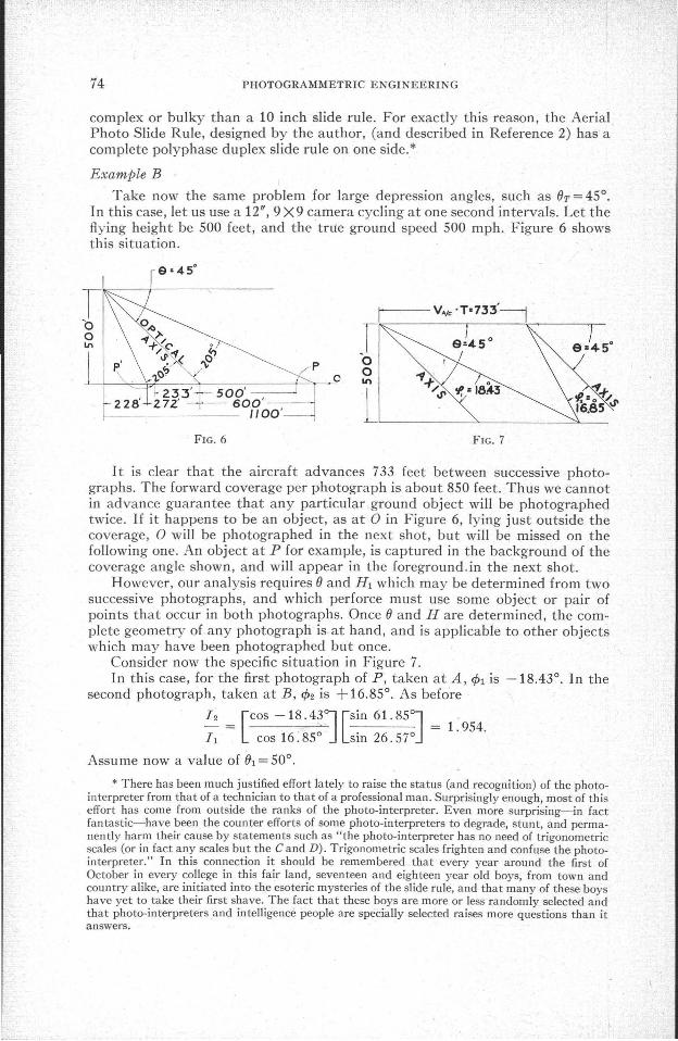
Take now the same problem for large depression angles, such as Or = 45°.In this case, let us use a 12", 9X9 camera cycling at one second intervals. Let theflying height be 500 feet, and the true ground speed 500 mph. Figure 6 showsthis situation.
FIG. 6
o
FIG. 7
I t is clear that the aircraft advances 733 feet between successive photographs. The forward coverage per photograph is about 850 feet. Thus we cannotin advance guarantee that any particular ground object will be photographedtwice. If it happens to be an object, as at 0 in Figure 6, lying just outside thecoverage, 0 will be photographed in the next shot, but will be missed on thefollowing one. An object at P for example, is captured in the background of thecoverage angle shown, and will appear in the foreground.in the next shot.
However, our analysis requires 0 and H l which may be determined from twosuccessive photographs, and which perforce must use some object or pair ofpoints that occur in both photographs. Once 0 and H are determined, the complete geometry of any photograph is at hand, and is applicable to other objectswhich may have been photographed but once.
Consider now the specific situation in Figure 7.In this case, for the first photograph of P, taken at A, cPl is -18.43°. In the
second photograph, taken at B, cP2 is +16.85°. As before
I 2 = [COS -18 .43oJ [Sin 61. 850J = 1. 954.
II COS 16.85° sin 26.57°
Assu me now a value of 01 = 50°.
* There has been much justified effort lately to raise the status (and recognition) of the photointerpreter from that of a technician to that of a professional man. Surprisingly enough, most of thiseffort has come from outside the ranks of the photo-interpreter. Even more surprising-in factfantastic-have been the counter efforts of some photo-interpreters to degrade, stunt, and permanently harm their cause by statements such as "the photo-interpreter has no need of trigonometricscales (or in fact any scales but the C and D). Trigonometric scales frighten and confuse the photointerpreter." In this connection it should be remembered that every year around the first ofOctober in every college in this fair land, seventeen and eighteen year old boys, from town andcountry alike, are initiated into the esoteric mysteries of the slide rule, and that many of these boyshave yet to take their first shave. The fact that these boys are more or less randomly selected andthat photo-interpreters and intelligence people are specially selected raises more questions than itanswers.
THE CALCULUS OF SCALE 75
We get
F(fh) = - 0.1135
and
- 1.282
yielding
- 0.0885 radians = - 5.07°.M=F(Or)
---=F'(Or)
Thus the first approximation to the 45° value of (Jr is (J = 44.93° showingagain fast convergence to (Jr.
How about really large errors in estimating (Jr?Take (Jr=300 (a 15° error), with the preceding data for 1>r and 1>2.
Again
F(Or) = sin 46.85° - 1. 97 sin 11. 57° = 0.3345
and
F'(Or) = cos46.85° - 1.97 cos 11.57° = 1.247
whence
(0.3345 )
/::,,0 = - = 0.2684 radians = 15.36°.-1. 247
Thus the first approximation to(Jr, is (Jr+f::,,() =45.36°, which is within 0.36°!!If this value of (J=45.36° is used as the.next approximation, the second ap
proximation will be found to be (J = 45.026°. Successive values of (J are 30°, 45.36°,45.026°.
Actually, the first approximation, 45.36° is good enough for any photo in-terpretation purpose.
PROBLEM FOUR: ALTITUDE, DIVE ANGLE, AND· SCALE DETERMINATION FROM FOR
WARD OBLIQUE PHOTOGRAPHY
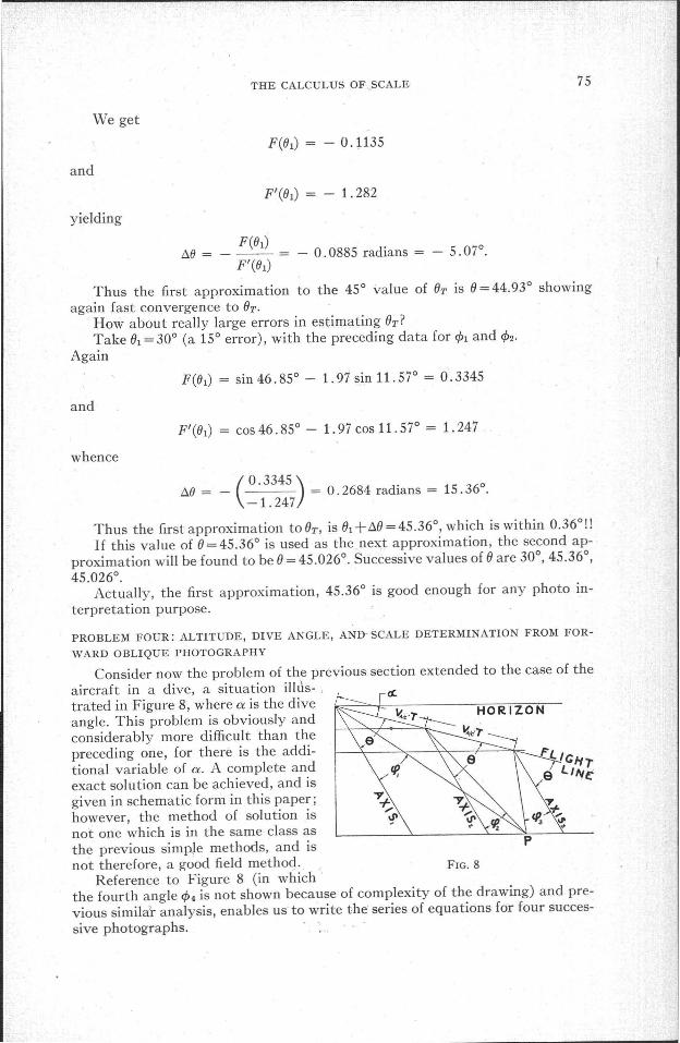
Consider now the problem of the previous section extended to the case of theaircraft in a dive, a situation illtls- ,trated in Figure 8, where a is the diveangle. This problem is obviously andconsiderably more difficult than thepreceding one, for there is the additional variable of a. A complete andexact solution can be achieved, and isgiven in schematic form in this paper;however, the method of solution isnot one which is in the same class asthe previous simpJe methods, and isnot therefore, a good field method. FIG. 8
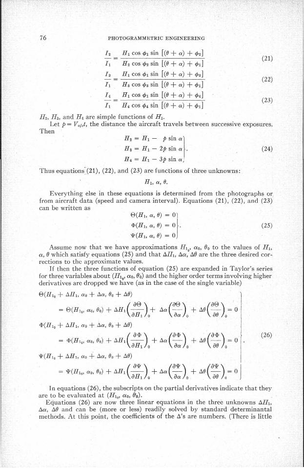
Reference to Figure 8 (in which·the fourth angle 1>4 is not shown because of complexity of the drawing) and previous similar analysis, enables us to write the series of equations for four successive photographs.
7'6 PHOTOGRAMMETRIC ENGINEERING
12 HI cos ¢1 sin [(8 + a) + ¢2](21)
II H 2 cos ¢2 sin [(8 + a) + ¢d
I a HI cos ¢1 sin [(8 + a) + ¢a](22)
II H a cos ¢a sin [(8 + a) + ¢d
14 HI cos ¢1 sin [(8 +a) + ¢4](23)-
II H 4 cos 4>4 sin [(8 + a) + ¢d
H 2, H a, and H 4 are simple functions of HI.Let p = Va/ct, the distance the aircraft travels between successive exposures.
Then
H 2 = HI - P sin a)H a = HI - 2p sin a .
H 4 = HI - 3p sin a
Thus equations~(21), (22), and (23) are functions of three unknowns:
(24)
(25)
Everything else in these equations is determined from the photographs or,from aircraft data (speed and camera interval). Equations (21), (22), and (23)can be written as
EJ(Ht, a, 8) = 0)
cf>(H1, a, 8) = 0).'!F(H 1 , a, 8) = 0
Assume now that we have approximations lI10 ' ao, ()o to the values of HI,a, () which satisfy equations (25) and that I:i.H1, l:i.a, I:i.() are the three desired corrections to the approximate values.
If then the three functions of equation (25) are expanded in Taylor's seriesfor three variables about '(H1o' ao, ()o) and the higher order terms involving higherderivatives are dropped we have (as in the case of the single variable)
)
(&e) (aEJ) Il:i.a -- + 1:i.8 - = 0aa 0 a8 0
EJ(H 10 + I:i.H 1 , ao + l:i.a, 80 + 118)
(aEJ)= EJ(H 10 ' ao, 80) + I:i.H 1 -- +aHI 0
cf>(H lo + I:i.H 1 , ao + l:i.a, 80 + 118)
(a<I> ) (acf> ) , (a<I»= <I>(H10' ao, 80) + I:i.H1 -- + l:i.a - + 118 - = 0
aHI 0 aa 0 a8 0
'!F(H lo + I:i.H 1 , ao +- l:i.a, 80+ 118)
= '!F(H 10' ao, 80) + I:i.H1 ( a'!F) + l:i.a (a'!F) + 118 (a'!F ) = 0 JaHI 0 aa o. a8 0
(26)
In equations (26), the subscript~on the partial derivatives indicate that theyare to be evaluated at (H10' ao, (fo). .
Equations (26) are now three linear equations in the three unknowns I:i.H1,
l:i.a, 1:i.(J and can be (more or less) readily solved by standard determinantalmethods. At this point, the coefficients of the I:i.'s are numbers. (There is little
THE CALCULUS OF SCALE 77
point to give the actual values of the partial derivatives here, for they wouldonly complicate the appearance of the equations.)
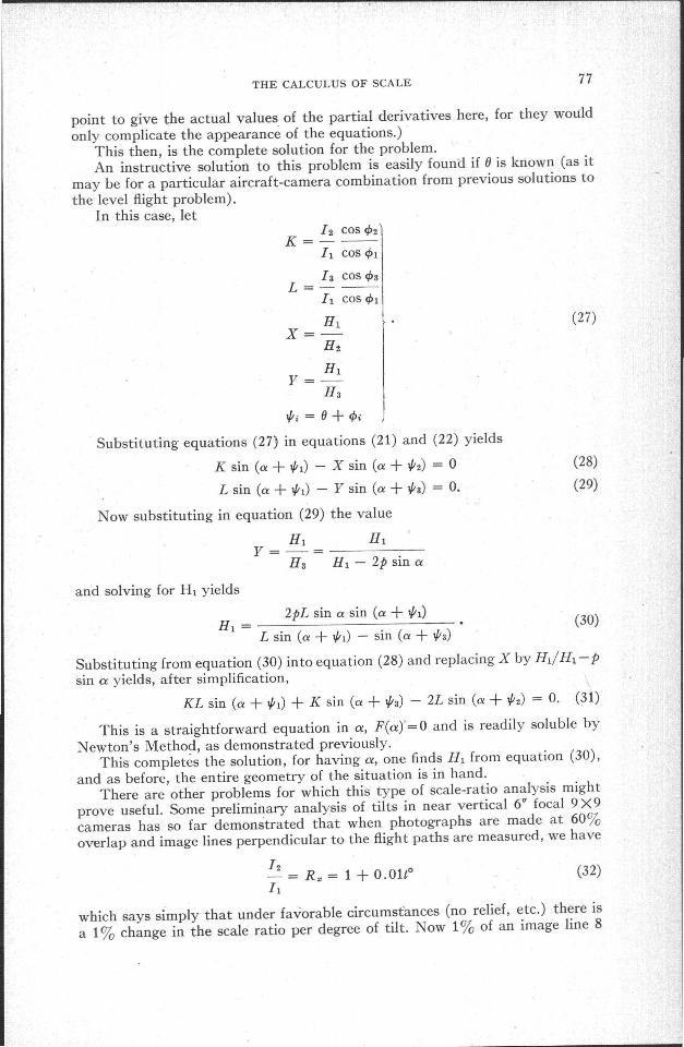
This then, is the complete solution for the problem.An instructive solution to this problem is easily found if (J is known (as it
may be for a particular aircraft-camera combination from previous solutions tothe level flight problem).
In this case, let12 COS <P2
K=--h cos <PI
1a cos <PaL=--
h COS <PI
HIX=-
H2
HIy=
Ha
V;i = (J + <Pi
Substituting equations (27) in equations (21) and (22) yields
K sin (a + V;l) - X sin (a + V;2) = 0
L sin (a + V;l) - Y sin (a + V;a) = O.
Now substituting in equation (29) the value
HI HIY=-=------
H a HI - 2p sin a
and solving for HI yields
(27)
(28)
(29)
(32)
2pL sin a sin (a + V;I)H1 = ~~
L sin (a + V;l) - sin (a + V;a)
Substituting from equation (30) into equation (28) and replacing X by HI/HI-Psin a yields, after simplification,
KL sin (a + V;l) + K sin (a + V;a) - 2L sin (a + V;2) = O. (31)
This is a straightforward equation in a, F(a)'=O and is readily soluble byNewton's Method, as demonstrated previously.
This completes the solution, for having a, one finds HI from equation (30),and as before, the entire geometry of the situation is in hand.
There are other problems for which this type of scale-ratio analysis mightprove useful. Some preliminary analysis of tilts in near vertical 6" focal 9 X 9cameras has so far demonstrated that when photographs are made at 60%overlap and image lines perpendicular to the flight paths are measured, we have
12- = K. = 1 + O. Olt°11
which says simply that under favorable circumstances (no relief, etc.) there isa 1% change in the scale ratio per degree of tilt. ow 1% of an image line 8
78 PHOTOGRAMMETRIC ENGINEERING
inches long is a sizeable and easily measured quantity. So it is clear that fairlysmall tilts yield measurable" results. These preliminary thoughts are just that.Mr. Eldon D. Sewell is working on some problems which may combine thisanalysis with the height-ditferencing methods; It is hoped some fruitful resultsmay soon be available for presentation in this journal.
IV. CONCLUSION AND ACKNOWLEDGMENT
The four problems discussed previously cannot be regarded as a completecatalog of solutions. The author has demonstrated a method, and a differentapproach. This different approach, if there is a common denominator to theseveral problems considered, is characterized by gathering and using moredata internal to the aircraft and its motions. What of the fellow in the fieldwhose problem is slightly different and which does not fit neatly into one ofthe enu~erated pigeon holes? If he can improvise his own methods, based, ifnecessary, on insights and suggestions found herein, he will be in good shape.If he insists on a made-to-order computing form for a non-routine problem,the author would be inclined to mistrust his results anyway. The foregoing isanother way of saying what has been said loud, long, and often before-we needat least a few people in the field who can improvise methods for riew problemson the spot. Routine problems are best handled routinely; but nonroutineproblems can never be so handled.
Most ideas are the direct or indirect by-product of stimulating conversation;the thoughts in this paper are no exception. To Col. Richard Philbrick, MajorJames Henry, Eldon D. Sewell, Dr. Sam Burka, Captain Walter Levison, andYale Katz, who, allowing themselves to be buttonholed, have shown interestwhen they could have legitimately shown boredom, much thanks. And sincethis paper was written at home, a special type of thanks to my wife.
REFERENCES
1. Katz, Amrom H., "A Problem at Inch'on," PHOTOGRAMMETRIC ENGINEERING, Vol. XVII, No.1,pp. 78-99, March 1951. "
2. Katz, Amrom H., "Contribution to the Theory and Mechanics of Photo-Interpretation FromVertical and Oblique Photographs," PHOTOGRAMMETRIC ENGINEERING, Vol. XVI, No.2, pp.339-386, June 1950.
3. Bridgman, Percy W., "The Logic of Modern Physics," The Macmillan Co., New York, 1932.
NEWS NOTE
THE NEW FA-181 SENSITIVE ALTIMETER
This new Sensitive Altimeter has been designed particularly to withstand the severest service in "the field. It meets the requirements of Military organizations. For durability, the Altimeter mechanism is supported by a shock mounting in a sturdy aluminumcase with a latched metal lid. The instrument case contains a desiccant to absorb moisture and the instrument may be completely sealed to prqtect it during transport. Thenew Altimeter employs the W&T Mechanism featuring the self-balancing principle andcustom calibration.
The W&T Palmer Altirule has been 'designed to compute elevations c'irectly fromobservations when using the two-base method. Information on the FA-181 Altimeter,the W&T Palmer Altirule and modern Altimetry methods is available from the manufacturer, Wallace & Tiernan Products, Inc., 1 Main Street, Belleville 9, New Jersey.