the basics of leds - lighting design lab of leds.pdf · the basics of leds developed by: ... almost...
TRANSCRIPT
1
THE BASICS of LEDs
DEVELOPED BY:
Eric Strandberg, LC & Jeff Robbins, LC, MIES
PRESENTED BY:
Jeff Robbins
Fall, 2012
2
LIGHTING DESIGN LAB
A Northwest utility funded lighting education facility
promoting commercial and industrial energy conservation.

3
OUR FACILITY

4
OUR FACILITY

5
OUR SERVICES
Lighting Classes (local and regional)
Demonstration Area
LDL LED Qualified Products List
Lighting Consultations
Website Resources
Outdoor Lighting Center
Technical Information
Product Evaluations
Mock-Up Facility
Lighting Library
Tours of Facility
Newsletter
Lighting Guides
General Information

6
WEBSITE
7
CONTENT OUTLINE
Part 1: The Basics Diode Defined
LED Defined
A Brief History
Advantages
How they Work
Lamp Anatomy
How They Produce Colors
How They Produce ‘White’ light
Fixture Anatomy
Part 2: Details A. Evaluating Light Output
B. Quality of Light
C. Fixture Efficacy 1. Off-state Power Consumption
2. Power Factor
3. Thermal Management
4. Useful Life
5. Driving and Powering
6. Controlling
7. Dimming
D. Questions to Ask
E. References
F. Terms and Terminology
8
Part 1: THE BASICS
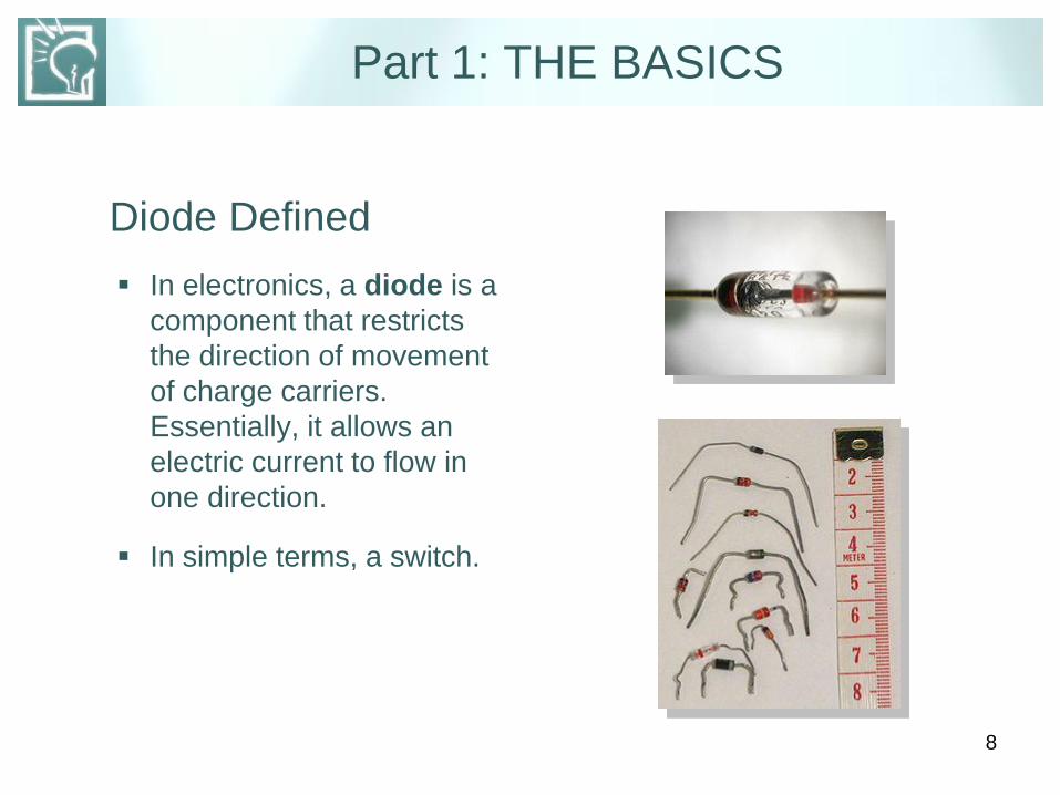
Diode Defined
In electronics, a diode is a
component that restricts
the direction of movement
of charge carriers.
Essentially, it allows an
electric current to flow in
one direction.
In simple terms, a switch.

9
LED Defined
A Light Emitting Diode is a semiconductor device that emits visible light of a certain color, and is fundamentally different from conventional light sources such as incandescent, fluorescent, and gas-discharge lamps, in that an LED:
uses no gas or filament, has no glass bulb,
and no failure-prone moving parts.
10
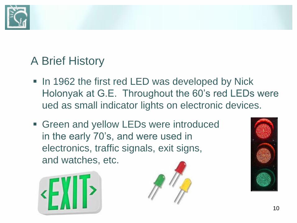
A Brief History
In 1962 the first red LED was developed by Nick
Holonyak at G.E. Throughout the 60’s red LEDs were
ued as small indicator lights on electronic devices.
Green and yellow LEDs were introduced
in the early 70’s, and were used in
electronics, traffic signals, exit signs,
and watches, etc.

11
A Brief History, (cont.)
By 1990, LEDs of one lumen output were available.
In 1993, Shuji Nakamura at Nichia created the first
high-brightness blue LED, making it possible to RGB
mix to any color.
This was followed in 1996 by the development of
Phosphor White LEDs, which combined a blue or
ultraviolet LED with a phosphor coating that produced
white light.

12
A Brief History, (cont.)
By 2005, output levels of 100 lumens were possible.
white light LEDs became available in various shades.
LEDs began competing with conventional light
sources and fixtures in general illumination
applications.
The Department of Energy expects LED technology
to become the preferred method of lighting in homes
and offices by 2025.

13
Advantages
Comparable in efficacy to
CFLs, gaining on
fluorescent tubes, and
incandescents.
Fixtures are directional,
allowing for more efficient
optics.
Quality of White Light LEDs
now comparable to CFLs,
recent advances assure
better consistency in color
and CCT.
Significantly longer ‘Useful’
life.
14
Advantages (cont.)
Light output has improved by 35% / year, while cost has dropped by 20% / year
No infrared, (IR) radiation
No ultraviolet, (UV) rays
Mercury free
Can operate in cold environments
Can withstand impact and vibrations
Inherently digital for ease of control
Instant on
Growing trend to modularity

15
0
How They Work Like a normal diode, the
LED consists of a chip of
semiconducting material
impregnated, or doped with
impurities to create a p-n,
(positive / negative) junction.
Atoms in the n-type
material have extra
electrons, atoms in the p-
type material have electron
holes.
16
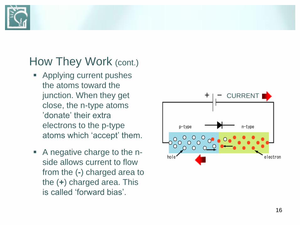
How They Work (cont.)
Applying current pushes
the atoms toward the
junction. When they get
close, the n-type atoms
’donate’ their extra
electrons to the p-type
atoms which ‘accept’ them.
A negative charge to the n-
side allows current to flow
from the (-) charged area to
the (+) charged area. This
is called ‘forward bias’.
CURRENT
17
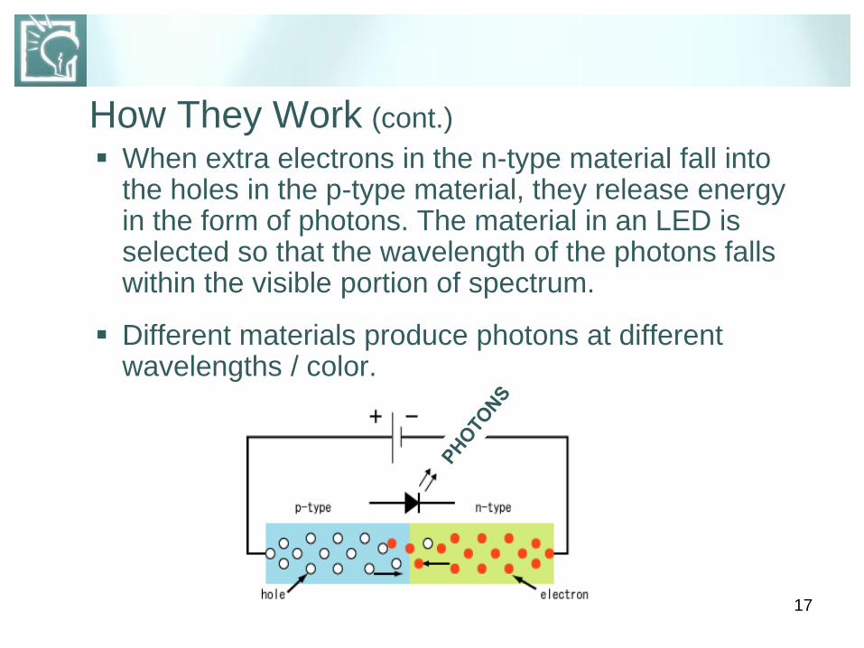
How They Work (cont.)
When extra electrons in the n-type material fall into the holes in the p-type material, they release energy in the form of photons. The material in an LED is selected so that the wavelength of the photons falls within the visible portion of spectrum.
Different materials produce photons at different wavelengths / color.

18
Lamp Anatomy, Indicator-Type
Typically 5mm
Usually inexpensive
Low Power
Generated heat
dissipated internally
Used only in:
Panel Displays
Electronic Devices
Instrument Illumination

19
Lamp Anatomy, Illuminator-Type
AKA surface-mount LEDs
High Brightness LEDs
Durable, high-power devices
Capable of providing:
Functional illumination
Light output equal to, or surpassing many conventional
sources

20
Lamp Anatomy, Illuminator-Type (cont.)
All Illuminator-Type LEDs share the same basic architecture: A semiconductor chip, (or die)
A substrate that supports the chip
Contacts to apply power
Bond wire to connect the contacts to the chip
Heat sink plus surface-mount solder
connections provide a thermally
conductive path
Lens
Outer casing
21
LEDs produce different colors by
using different material systems,
each system producing photons
of different wavelengths.
Illuminator-Type LEDs use
systems which can handle the
necessary heat, current, and
humidity to produce high-
brightness red and amber, (Alln-
GaP), and high-brightness blue,
green and cyan, (InGaN).
Alln-GaP and InGan cover
almost the entire spectrum.
A gap occurs in the yellow-
green portion, which can
be filled by including
different color LEDs in the
same device.
How They Produce Colors
22
How They Produce
Colors (cont.)
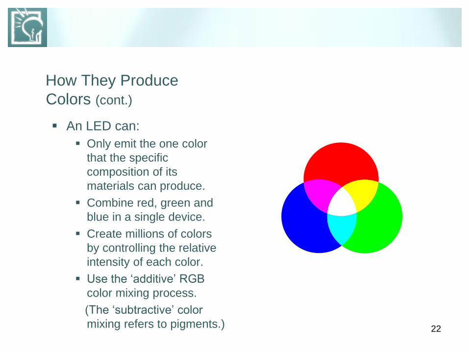
An LED can:
Only emit the one color
that the specific
composition of its
materials can produce.
Combine red, green and
blue in a single device.
Create millions of colors
by controlling the relative
intensity of each color.
Use the ‘additive’ RGB
color mixing process.
(The ‘subtractive’ color
mixing refers to pigments.)
23
How They Produce Colors (cont.)
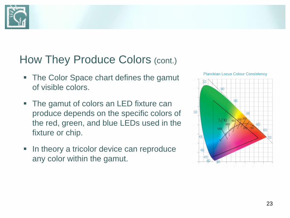
The Color Space chart defines the gamut
of visible colors.
The gamut of colors an LED fixture can
produce depends on the specific colors of
the red, green, and blue LEDs used in the
fixture or chip.
In theory a tricolor device can reproduce
any color within the gamut.
24
How They Produce ‘White’ Light
Method 1 – RGB mixing (previously covered)
Better control over exact color.
Is hardware intensive / expensive
Tends to make pastels look unnatural, hence poor CRI
25
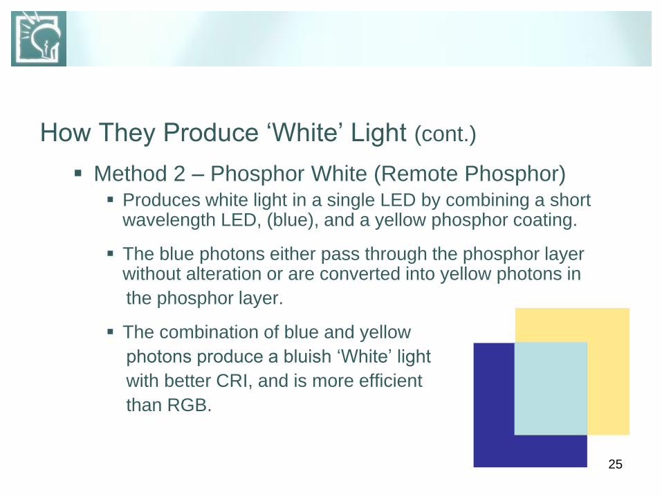
How They Produce ‘White’ Light (cont.)
Method 2 – Phosphor White (Remote Phosphor) Produces white light in a single LED by combining a short
wavelength LED, (blue), and a yellow phosphor coating.
The blue photons either pass through the phosphor layer without alteration or are converted into yellow photons in
the phosphor layer.
The combination of blue and yellow
photons produce a bluish ‘White’ light
with better CRI, and is more efficient
than RGB.
26
Fixture Anatomy
To be used for illumination, LEDs must be integrated
into systems that incorporate:
Optics – Reflector cups, lensing and aiming features
Drivers – Microprocessor-based power management,
and control stages
Power Supplies – voltage conversion units
Thermal Management – vents and heat sinks
Well designed fixtures integrate all these features into
the fixture itself.
Effectively erases the distinction between lamp & luminaire.
27
Part 2: DETAILS
A. Evaluating Light Output
1. Light Output Defined
2. The Trouble with Lumen Evaluation
3. Delivered Light
4. Relative Photometry
5. Absolute Photometry
6. Sources of Light Loss
28
1. Light Output Defined
How much light a fixture produces, and how the fixture emits and
distributes that light.
Data describing the quantity and distribution of the visible light produced
is photometrics.
The specification most commonly used for evaluating and comparing
the performance of ‘conventional’ lighting fixtures is lumen output.
29
2. The Trouble with Lumen Evaluation
The way that lumen output is traditionally measured, reported and
interpreted is a problem for evaluating and comparing LED fixtures.
Lumens are an imperfect measurement of the ‘perceived’ intensity
of light.
LED fixtures and conventional fixtures are tested differently, hence
some photometric data is reported differently.
A fixture’s total lumen output does not account for wasted light.
LED fixtures typically waste less light than conventional fixtures.
‘Eye Sensitivity Curve’ adjusts lumen content by source’s Spectral
Powder Distribution.
30
3. Delivered Light
Instead of lumen output, it is the most relevant measurement
for evaluating LED fixtures and for making accurate
comparisons to conventional fixtures.
Describes how much ‘Useful Light’ a fixture can deliver to the
task area. ‘Useful Light’ is the portion of a fixture’s output that
is effectively delivered to the task area, discounting any
wasted light.
31
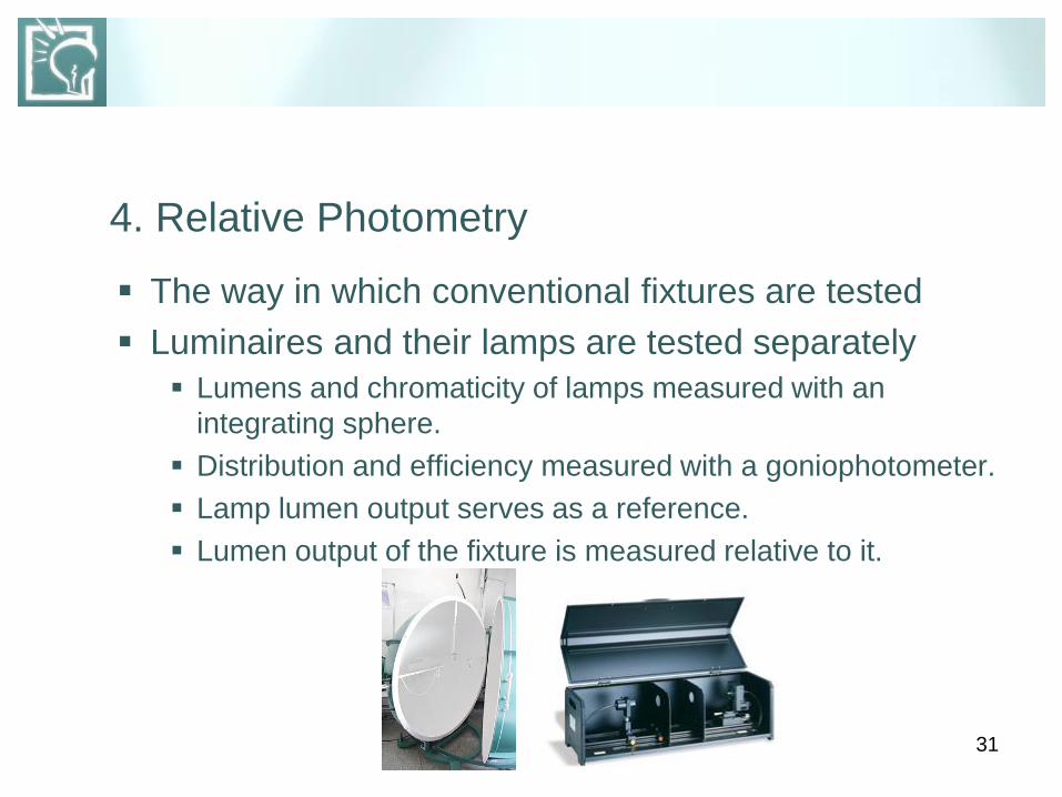
4. Relative Photometry
The way in which conventional fixtures are tested
Luminaires and their lamps are tested separately
Lumens and chromaticity of lamps measured with an
integrating sphere.
Distribution and efficiency measured with a goniophotometer.
Lamp lumen output serves as a reference.
Lumen output of the fixture is measured relative to it.

32

33
5. Absolute Photometry
The way in which LED fixtures are tested
The approved procedures and testing conditions are listed in
IES LM-79-08, “Electrical and Photometric Measurements
of Solid-State Lighting Products”.
Because LEDs are inseparable from their fixtures,
only fixture lumens measured, not lamp lumens.
For a valid comparison, the measured lamp lumens
of a conventional fixture must be reduced by its
efficiency, as reported in a Zonal Lumen Summary
chart.

34
Zone Lumen %Lamp %Fixt.
0-30 113 12.1 19.6
0-40 199 23.1 34.6
0-60 382 44.4 66.3
0-90 534 62.1 92.8
90-120 38 4.4 92.8
90-130 40 4.7 7.0
90-150 41 4.8 7.2
90-180 41 4.8 7.2
0-180 550 66.9 100
ZONAL LUMEN SUMMARY
Lamp Lumens = 820
35
6. Sources of Light Loss
Delivered light to the task surface depends on a
range of factors:
Lumen output and lamp lumen depreciation
Fixture positioning
Lensing, filtering, shading, and accessories to redirect or
alter the output
-BUT-
LED fixtures are inherently directional, minimizing losses
LEDs are natively colored, also minimizing losses

36
Part 2: DETAILS
B. Quality of Light
1. CRI & White Light LEDs
2. CRI vs. CQS
3. Color Consistency
37
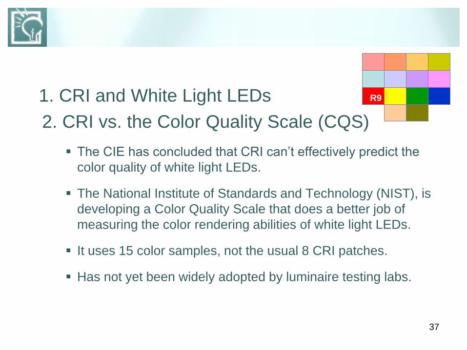
1. CRI and White Light LEDs
2. CRI vs. the Color Quality Scale (CQS)
The CIE has concluded that CRI can’t effectively predict the
color quality of white light LEDs.
The National Institute of Standards and Technology (NIST), is
developing a Color Quality Scale that does a better job of
measuring the color rendering abilities of white light LEDs.
It uses 15 color samples, not the usual 8 CRI patches.
Has not yet been widely adopted by luminaire testing labs.
R9
38
3. Color Consistency
An index of light quality for both color and white
light LEDs.
Uses CCT, which allows for a range of variation in
chromaticity that can be discerned by viewers,
even if the CCT value is the same.
Manufacturers strive to keep color variations under
control.
39
3.1 Color Consistency (cont.)
Understanding CCT and Binning
Light sources with the same defined CCT can display
discernible differences in hue.
LED makers use a method of managing manufacturing
variations in chromaticity and CCT known as ‘Binning’.
The threshold at which a color difference becomes
perceptible is defined by a MacAdam Ellipse. A color difference of 1 step is not visible.
A color difference of 2-4 steps is barely visible.
A color difference of 5 or more steps is readily noticeable.
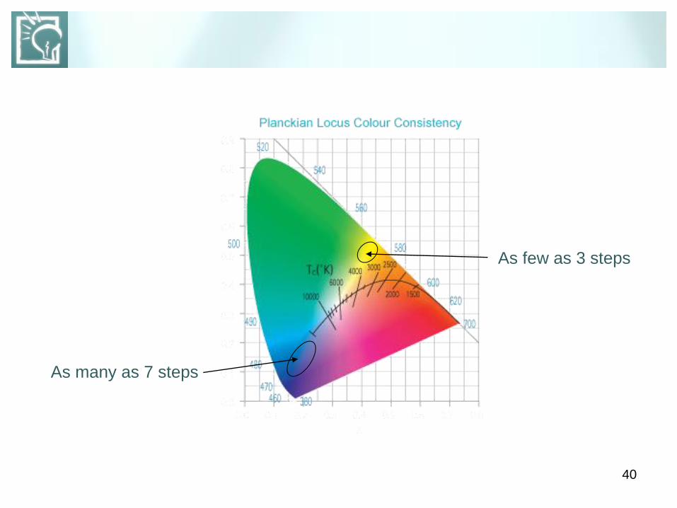
40
As many as 7 steps
As few as 3 steps

41
Part 2: DETAILS
C. Fixture Efficacy
1. Off-State Power Consumption
2. Power Factor
3. Thermal Management
4. Useful Life
5. Driving & Powering
6. Controlling
7. Dimming
8. Trend toward Modularity
42
1. Off-State Power Consumption
Can significantly reduce system efficacy.
Occurs when fixture switches or dimmers are positioned
between the power supply or transformer, and the fixtures.
Transformer continues to draw power even when the fixtures
are off.
Transformer power can draw in excess of 2 watts.
The resulting total cumulative losses can represent as much
as 20% of a system’s load.
43
2. Power Factor (PF)
A measure of how effectively a device converts electric
current into useful output power.
Real Power (Watts)
Apparent Power (Volt-Amps)
EXAMPLE: An LED lamp rated at 18 watts, when measured
actually draws 20 volt-amps. The PF of that lamp/driver
is18W / 20VA, which is 0.9, and is considered high.
EXAMPLE: A CFL lamp rated at 18 watts, when measured,
actually draws 30 volt-amps. The PF of that lamp/ballast is
18W / 30VA, which is 0.6, and is considered low.
44
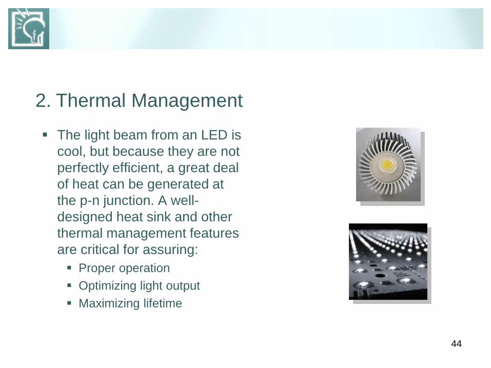
2. Thermal Management
The light beam from an LED is
cool, but because they are not
perfectly efficient, a great deal
of heat can be generated at
the p-n junction. A well-
designed heat sink and other
thermal management features
are critical for assuring:
Proper operation
Optimizing light output
Maximizing lifetime

45
2.1 Thermal Management (cont.)
Junction Temperature
As it increases, output and ‘lifetime’ decrease
Factors are:
– Drive current
– Thermal path
– Ambient temperature
46
2.2 Thermal Management (cont.)
Junction Temperature
Affect on Light Output
– Manufacturers measure at fixed junction temp. of 25oC.
– Actual range of temperatures: 60oC. to 90oC.
– Result is at least 10% less light than manufacturer rating.
Affect on Useful Life
– An increase of 11oC. can reduce lifetime by 50%+.
47
3. Useful Life
Rated Lamp Life of Conventional Sources
Well established methodology: LM-49, LM-65,
Life rated at 50% failure point
Lumen Maintenance and Depreciation
IES publication LM-80-08
Counterpoint to LM-49 and LM-65
Instead of rated life, LM-80 measures lumen depreciation
Factors include:
– Drive current
– Heat generated within the device
48
3.1 Useful Life (cont.)
Lumen Maintenance and Depreciation (cont.)
Maintenance measurement: Lp
L is initial output
P is the percentage maintained over a number of hours
i.e. L70 measure how long a source will retain 70%,
(or lose 30% of its initial output)
Knowing an LED’s Useful Life is important because they continue to deliver light after initial output has decreased by 50%., or more. Users need to know how long an LED fixture will retain a meaningful percentage of its initial light output, NOT how long will it take to fail.

49
3.2 Useful Life (cont.)
Useful Life Defined
The length of time a light source delivers a minimum
acceptable level of light in a given application.
Changes in light levels go undetected down to 70% of initial
levels, especially if change is gradual.
For general lighting applications, Useful Life could therefore
be defined as the length of time it takes an LED source to
reach 70% of its initial output, L70
For decorative applications, (and for Energy Star), Useful Life
can be rated as low as L50
50
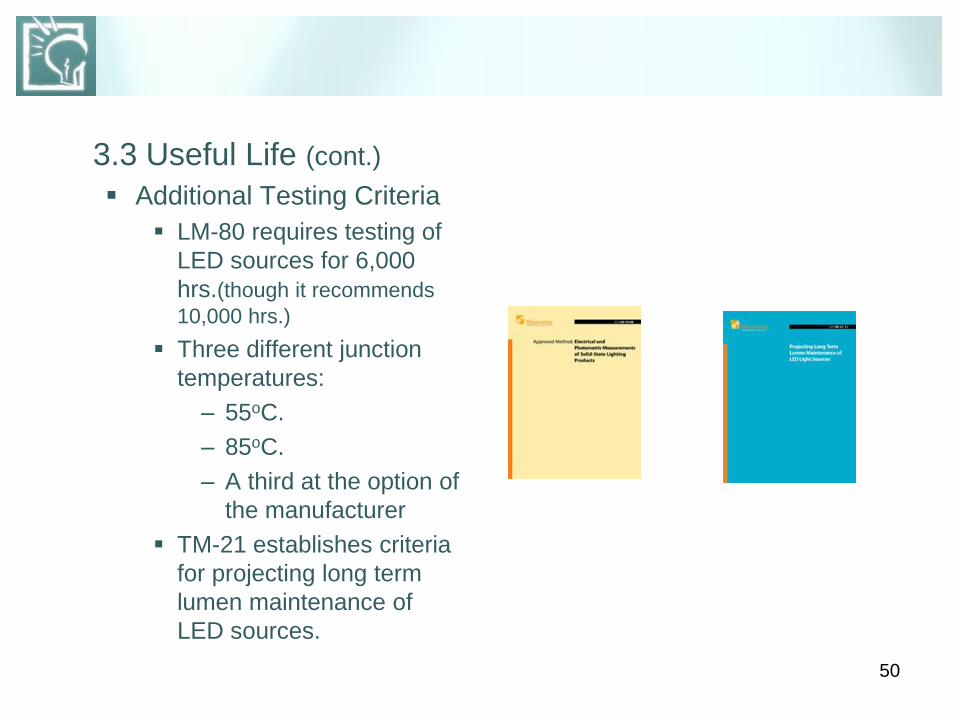
3.3 Useful Life (cont.)
Additional Testing Criteria
LM-80 requires testing of
LED sources for 6,000
hrs.(though it recommends
10,000 hrs.)
Three different junction
temperatures:
– 55oC.
– 85oC.
– A third at the option of
the manufacturer
TM-21 establishes criteria
for projecting long term
lumen maintenance of
LED sources.

51
3.4 Useful Life (cont.)
Useful Life of LED Sources in Fixtures
LM-79 calls for the testing of complete lighting fixtures.
Measuring lumen maintenance requires the testing of LED
sources.
LM-80 testing for complete LED fixtures would be complex
and expensive.
In practice, reputable fixture manufacturers ensure drive
current and operating temperatures fall within the range of
source manufacturer’s lumen maintenance reports, they
make calculations of the Useful Life of the LED sources they
are integrating into their fixtures.

52
3.5 Useful Life (cont.)
Comparing Useful Life – LED to Conventional
60-watt incandescent, LLD* of 15%, rated life of 1,000 hrs.
– 10% loss at 600 hrs. Useful life is 1,800 hrs.
– Lamp will fail before L70.
– Rated Life is its Useful Life
18-watt CFL, LLD* of 10%, rated life of 15,000 hrs.
– 10% loss at 6,000 hrs. Useful life is 18,000 hrs.
– Lamp will fail before L70.
– Rated Life is Useful Life
*Light Lumen Depreciation

53
3.6 Useful Life (cont.)
Comparing Useful Life – LED to Conventional
32-watt HP T8, LLD of 5%, Rated Life of 60,000 hrs.
5% loss at 24,000 hrs. Useful Life of 79,200 hrs.
Lamp will fail before L70. Rated Life is Useful Life.
Conclusion: Comparisons of conventional fixtures to LED fixtures must
be on a Rated Life-to-Useful Life basis.

54
4. Driving and Powering
LED Driver
An electronic circuit that converts input power into a current
source in which current remains constant despite fluctuations
in voltage.
Fixtures that feature integrated LED drivers are as easy to
connect to power as any conventional fixture.
An increasing number of integrated drivers for white light
LED fixtures are dimmable.
55
4.1 Driving and Powering (cont.)
Power Options for LED Fixtures
Low-Voltage Power Distribution
– Requires a low-voltage power supply (brick)
– Lighter weight and portable
– Favored by the Entertainment industry
– Relatively inefficient due to losses
56
4.2 Driving and Powering (cont.)
Power Options for LED Fixtures
Onboard Power Integration
Uses same overall control scheme as low-voltage systems
but offers advantages:
– Replaces external low-voltage power supply with
standard switching power supply integrated into the
fixture.
– This allows fixtures to be connected directly to line
voltage, fewer losses occur.
– Additional components can increase fixture size and
thermal load.
57
4.3 Driving and Powering (cont.)
Power Options for LED Fixtures
Inboard Power Integration
– Integrates a single efficient power stage into the fixture
itself
– Eliminates a significant percentage of power losses
associated with low-voltage configurations with multiple
stages
– Advantages include increased system efficiency, and
lower cost and complexity of installation, operation, and
maintenance
58
5. Controlling
Control is a general term for a wide range of methods,
protocols, and devices used to operate fixtures:
– DMX, the most commonly used and accepted control format
for color changing fixtures.
– Ethernet, a computer network not limited by addressing
issues.
– Other Options:
DALI
59
6. Dimming
LED fixtures can be dimmed two different ways
depending on the type and capabilities of the fixtures:
Using DMX and other Control Interfaces - color changing and
tunable white fixtures can be dimmed via DMX or other
control protocol
Using Commercially available Dimmers
– Solid color and white fixtures can be dimmed via compatible,
commercially available dimmers
– Most drivers use Pulse Width Modulation, ON time dimming
– Most are incompatible with incandescent and leading edge
dimmers, (visible flicker at low levels).
60
6.1 Dimming (cont.)
Using Commercially available Dimmers
Many LED fixtures work best with electronic low voltage, (ELV-type) dimmers, (though magnetics are quieter).
Fixtures that work with magnetic transformers, such as MR16 compatible LED lamps, require magnetic low voltage (MLV-type) dimmers.
Most ELV-type dimmers use trailing edge technology, which performs more reliably, with its 3-wire, extra neutral.
Trailing edge dimmers not as common, which is no problem in new construction, may require swapping existing leading edge dimmers for trailing edge types in retro-fits.
Manufacturers have lists of tested and approved dimmers.
61
6.2 Dimming (cont.)
Dimmer Thresholds and Wattage
Effective dimming threshold around 10%
Trim-pot screw controls minimum dimming level
Wattage of dimmer must be sufficient for the installation
Number of fixtures to be controlled times wattage of each
fixture equals the minimum dimmer wattage
High-resolution 12-bit or 16-bit drivers virtually eliminate
visible flicker, and can be dimmed below the 10% threshold.
62
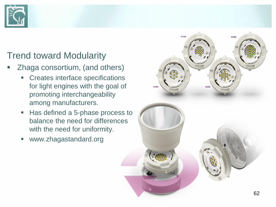
Trend toward Modularity
Zhaga consortium, (and others)
Creates interface specifications
for light engines with the goal of
promoting interchangeability
among manufacturers.
Has defined a 5-phase process to
balance the need for differences
with the need for uniformity.
www.zhagastandard.org
63
D. Questions to ask of any lighting system
1. How much light will they produce?
Lumens
Footcandles
2. How much energy will they save?
3. What is the light quality? Color Temperature (CCT)
Color Rendering (CRI, or other metric)
Color Consistency (binning)
4. Will they save any money?
64
www.energystar.gov
www.lrc.rpi.edu/programs
/solidstate
www1.eere.energy.gov/
buildings
REFERENCES
65
TERMS & TERMINOLOGY
Absolute Photometry
The standard method for testing light output and distribution of
lighting fixtures.
Binning
Term for the production and sorting method used by LED makers to
insure that what they make conforms to specifications for forward
voltage, color, and luminous flux.
Controller
A device that controls the output of color changing and tunable white
lighting fixtures.
Digital Addressable Lighting Interface (DALI)
A digital communications protocol for controlling and dimming lighting
fixtures.

66
Delivered Light
The amount of light a luminaire or system delivers to the target area of
task surface, measured in footcandles, (fc).
DMX
A digital communications protocol for controlling luminaires.
ELV-type dimmer
An electronic low voltage dimmer used to control LED luminaires with
electronic transformers.
Ethernet
A digital communications protocol used in computer networks. Can
control Ethernet compatible LED luminaires.
Forward voltage
Occurs when a negative charge is applied to the n-type side of a diode,
allowing current to flow from the negatively-charged area, to the
positively-charged area.

67
GaAsP
Gallium arsenide phosphide material used in indicator-type LED’s
producing light in the red to yellow-green portion of the visible spectrum.
GaP
Gallium phosphide material used in indicator-type LED’s producing light
in the green to orange portion of the visible spectrum.
Ghosting
An effect that occurs when luminaires in the OFF state faintly glow as a
result of residual voltage in the circuit.
HB-LED’s / HP-LED’s
High-brightness or power LED’s. A synonym for indicator-type LED’s.
Heat sink
A feature or device that conducts or convects heat away from sensitive
components.
68
Illuminator-type LED’s
High performance, high power LED’s capable of providing functional illumination.
Inboard power integration
An approach to power management that integrates the power supply into a luminaire’s circuitry, creating an efficient power state that consolidates line voltage conversion and LED current regulation.
Indicator-type LED’s
Inexpensive, low power LED’s suitable for use as indicator lights in panel displays, or instrument illumination, etc.
InGaN
Indium gallium nitride material used in green, blue, and cyan LED’s.
LED Driver
An electronic circuit that converts input power into a current source in which current remains constant despite fluctuations in voltage.
69
Lumen maintenance
Describes how long a light source will retain a certain % of its initial lumen output. L70 is the length of time a source retains 70% of its initial lumen output.
Luminous efficiency
Percentage of lamp lumens a conventional fixture emits, minus blocked or wasted light.
MacAdam ellipse
An ellipse, laid over a color space that defines the threshold at which color difference becomes visible.
Material system
Material, such as AllnGaP, or InGaN, used within an LED to produce light of a certain color.
70
Phosphor white Method of producing white light in a single LED by combining a short-
wavelength LED such as blue or UV, and a yellow phosphor coating.
Photon The basic unit of electromagnetic radiation, including visible light
p-n junction The location within an LED where negatively charged material donates
extra electrons to positively charged material, which accepts them, releasing energy in the form of photons.
Pulse width modulation Method used by most LED drivers to regulate the amount of power to
the LEDs. PWM turns LEDs on and off at high frequency, reducing total ON time to achieve a desired dimming level.
Relative photometry Method for testing the output and distribution of conventional fixtures
where the fixture is measured relative to its lamps.
71
Remote phosphor
A technique that separates the phosph0r from the chip in a white light LED, improving and extracting efficiency of emitted light.
Trailing-edge dimmer
Type of dimmer that regulates power to lamps by delaying the end of each half cycle of AC power. Compatible with many LED fixtures.
Tunable white light
White light LED fixtures that combine channels of warm white and cool white LEDs to produce a range of colors.
Useful life
Length of time it takes an LED source to reach a certain % of its initial lumen output. Commonly known as lumen maintenance thresholds. L70, 70% if initial lumen output. L50, 50% of initial lumen output.
Useful light
Amount of light a fixture delivers in an application, less any wasted light.
72
CALL, VISIT OR CLICK!
206.325.9711
800.354.3864
LIGHTING DESIGN LAB
2915 – 4th Avenue South
Seattle, WA 98119
www.lightingdesignlab.com