the 2.0 l 110 kw engine with petrol direct injection (fsi) · the 2.0 l 110 kw engine with petrol...
TRANSCRIPT

27
9
Service.
279
Self Study Programme 279
For internal use only
All rights reserved. Subject to technical modification.AUDI AGDepartment I/VK-35D-85045 IngolstadtFax 0841/89-36367240.2810.98.20Technical status as at 12/01Printed in Germany
The 2.0 l 110 kW engine with petrol direct injection (FSI)
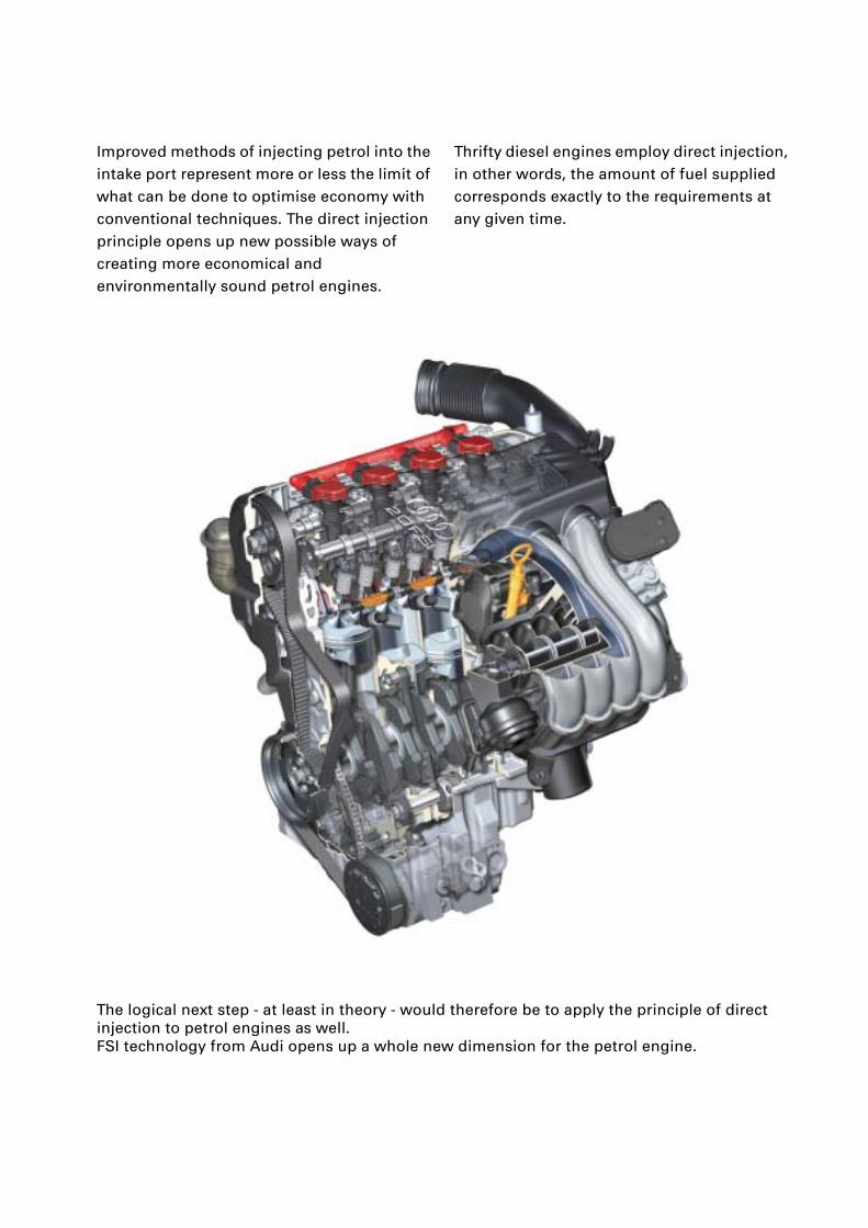
Improved methods of injecting petrol into the intake port represent more or less the limit of what can be done to optimise economy with conventional techniques. The direct injection principle opens up new possible ways of creating more economical and environmentally sound petrol engines.
Thrifty diesel engines employ direct injection, in other words, the amount of fuel supplied corresponds exactly to the requirements at any given time.
The logical next step - at least in theory - would therefore be to apply the principle of direct injection to petrol engines as well.FSI technology from Audi opens up a whole new dimension for the petrol engine.

3
Contents
Page
AttentionNoteNew
The Self Study Programme contains information on design features and functions.
The Self Study Programme is not intended as a Workshop Manual. Values given are only intended to help explain the subject matter and relate to the software version applicable when the SSP was compiled.
Use should always be made of the latest technical publications when performing maintenance and repair work.
Introduction
Highlights of the FSI engine. . . . . . . . . . . . . . . . . . . . . . . . . . . . . . . . . . . . . . . . . . . . 42.0 l FSI engine. . . . . . . . . . . . . . . . . . . . . . . . . . . . . . . . . . . . . . . . . . . . . . . . . . . . . . . 5
Engine
Crankcase breather . . . . . . . . . . . . . . . . . . . . . . . . . . . . . . . . . . . . . . . . . . . . . . . . . . . 6Pistons . . . . . . . . . . . . . . . . . . . . . . . . . . . . . . . . . . . . . . . . . . . . . . . . . . . . . . . . . . . . . 7Oil circulation. . . . . . . . . . . . . . . . . . . . . . . . . . . . . . . . . . . . . . . . . . . . . . . . . . . . . . . . 7Cylinder head . . . . . . . . . . . . . . . . . . . . . . . . . . . . . . . . . . . . . . . . . . . . . . . . . . . . . . . . 8Camshaft positioning . . . . . . . . . . . . . . . . . . . . . . . . . . . . . . . . . . . . . . . . . . . . . . . . 11Lower part of intake manifold . . . . . . . . . . . . . . . . . . . . . . . . . . . . . . . . . . . . . . . . . 12Intake air routing . . . . . . . . . . . . . . . . . . . . . . . . . . . . . . . . . . . . . . . . . . . . . . . . . . . . 13System components . . . . . . . . . . . . . . . . . . . . . . . . . . . . . . . . . . . . . . . . . . . . . . . . . .14CAN bus interfaces . . . . . . . . . . . . . . . . . . . . . . . . . . . . . . . . . . . . . . . . . . . . . . . . . . 16Engine control unit . . . . . . . . . . . . . . . . . . . . . . . . . . . . . . . . . . . . . . . . . . . . . . . . . . 17Modes of operation. . . . . . . . . . . . . . . . . . . . . . . . . . . . . . . . . . . . . . . . . . . . . . . . . . 17Stratified charge operation . . . . . . . . . . . . . . . . . . . . . . . . . . . . . . . . . . . . . . . . . . . 18Homogeneous operation . . . . . . . . . . . . . . . . . . . . . . . . . . . . . . . . . . . . . . . . . . . . . 20Fuel system . . . . . . . . . . . . . . . . . . . . . . . . . . . . . . . . . . . . . . . . . . . . . . . . . . . . . . . . 24Single-plunger high-pressure pump . . . . . . . . . . . . . . . . . . . . . . . . . . . . . . . . . . . . 26Fuel metering valve -N290 . . . . . . . . . . . . . . . . . . . . . . . . . . . . . . . . . . . . . . . . . . . . 28Fuel rail . . . . . . . . . . . . . . . . . . . . . . . . . . . . . . . . . . . . . . . . . . . . . . . . . . . . . . . . . . . . 29Fuel pressure sender -G247 . . . . . . . . . . . . . . . . . . . . . . . . . . . . . . . . . . . . . . . . . . . 30High-pressure injectors -N30, -N31,-N32, -N33 . . . . . . . . . . . . . . . . . . . . . . . . . . . 31Exhaust system . . . . . . . . . . . . . . . . . . . . . . . . . . . . . . . . . . . . . . . . . . . . . . . . . . . . . 32Exhaust-gas temperature sender -G235 . . . . . . . . . . . . . . . . . . . . . . . . . . . . . . . . . 32Exhaust gas treatment system. . . . . . . . . . . . . . . . . . . . . . . . . . . . . . . . . . . . . . . . . 33NOx storage catalytic converter . . . . . . . . . . . . . . . . . . . . . . . . . . . . . . . . . . . . . . . . 33Regeneration phases . . . . . . . . . . . . . . . . . . . . . . . . . . . . . . . . . . . . . . . . . . . . . . . . 34NOx sender -G295 . . . . . . . . . . . . . . . . . . . . . . . . . . . . . . . . . . . . . . . . . . . . . . . . . . . 36Exhaust-gas temperature sender -G235 . . . . . . . . . . . . . . . . . . . . . . . . . . . . . . . . . 36Exhaust-gas recirculation . . . . . . . . . . . . . . . . . . . . . . . . . . . . . . . . . . . . . . . . . . . . . 37Block diagram . . . . . . . . . . . . . . . . . . . . . . . . . . . . . . . . . . . . . . . . . . . . . . . . . . . . . . 38Special tools. . . . . . . . . . . . . . . . . . . . . . . . . . . . . . . . . . . . . . . . . . . . . . . . . . . . . . . . 40
4
Introduction
279_041
279_030279_025
279_007
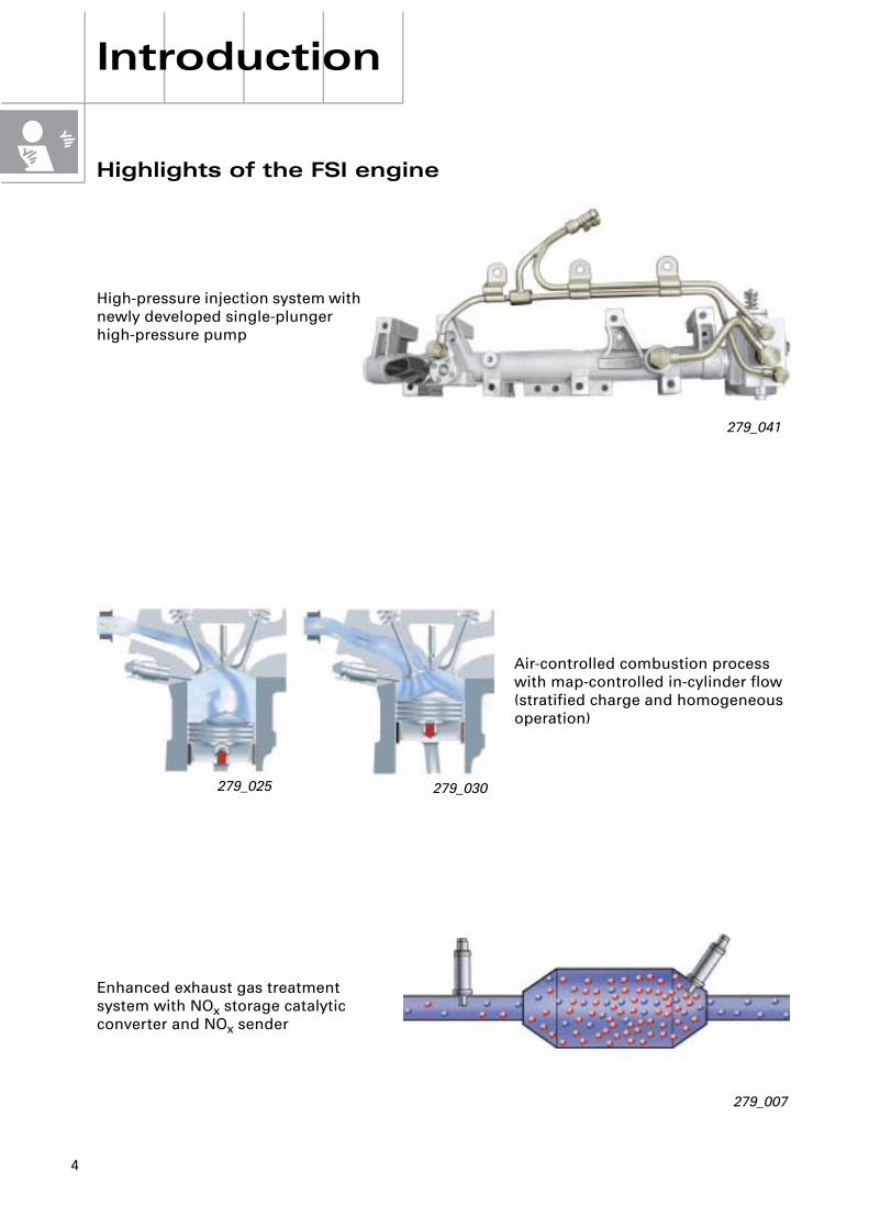
Highlights of the FSI engine
Air-controlled combustion process with map-controlled in-cylinder flow (stratified charge and homogeneous operation)
Enhanced exhaust gas treatment system with NOx storage catalytic converter and NOx sender
High-pressure injection system with newly developed single-plunger high-pressure pump
5
279_008
Torq
ue
[Nm
]
Pow
er [k
W]
Engine speed rpm279_001
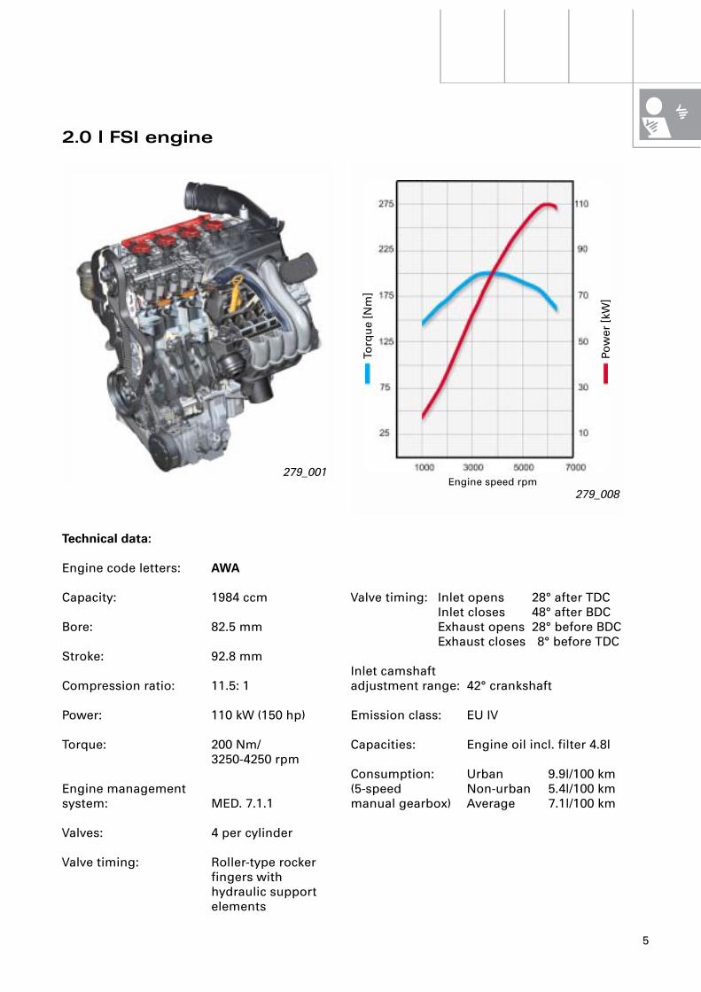
Valve timing: Inlet opens 28° after TDCInlet closes 48° after BDCExhaust opens 28° before BDCExhaust closes 8° before TDC
Inlet camshaftadjustment range: 42° crankshaft
Emission class: EU IV
Capacities: Engine oil incl. filter 4.8l
Consumption: Urban 9.9l/100 km(5-speed Non-urban 5.4l/100 kmmanual gearbox) Average 7.1l/100 km
2.0 l FSI engine
Technical data:
Engine code letters: AWA
Capacity: 1984 ccm
Bore: 82.5 mm
Stroke: 92.8 mm
Compression ratio: 11.5: 1
Power: 110 kW (150 hp)
Torque: 200 Nm/3250-4250 rpm
Engine management system: MED. 7.1.1
Valves: 4 per cylinder
Valve timing: Roller-type rocker fingers with hydraulic support elements
6
Engine
279_046
279_009
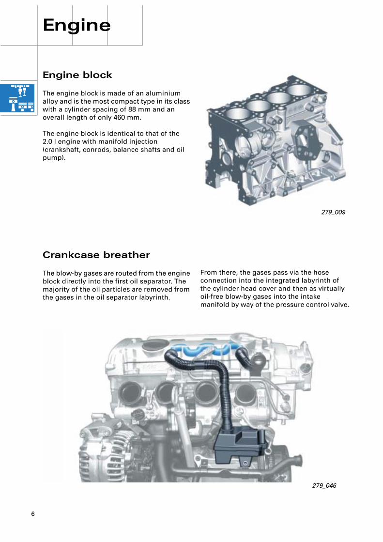
From there, the gases pass via the hose connection into the integrated labyrinth of the cylinder head cover and then as virtually oil-free blow-by gases into the intake manifold by way of the pressure control valve.
Engine block
The engine block is made of an aluminium alloy and is the most compact type in its class with a cylinder spacing of 88 mm and an overall length of only 460 mm.
The engine block is identical to that of the 2.0 l engine with manifold injection (crankshaft, conrods, balance shafts and oil pump).
Crankcase breather
The blow-by gases are routed from the engine block directly into the first oil separator. The majority of the oil particles are removed from the gases in the oil separator labyrinth.
7
279_011
279_010
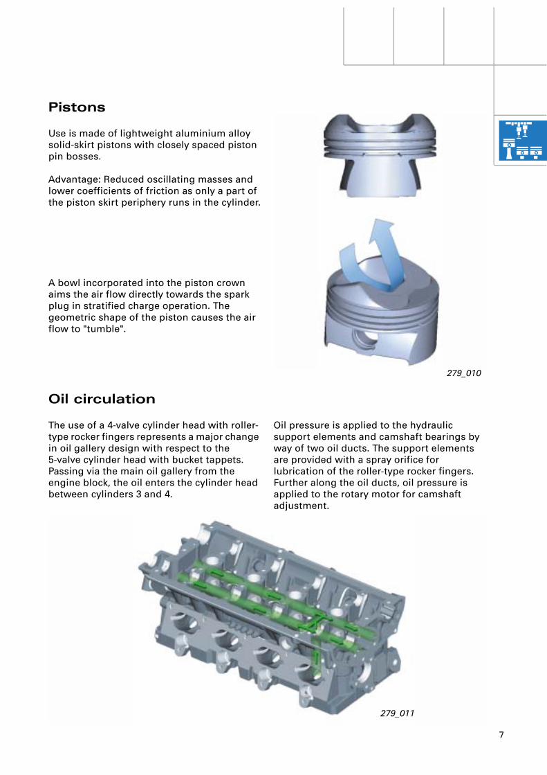
Pistons
Use is made of lightweight aluminium alloy solid-skirt pistons with closely spaced piston pin bosses.
Advantage: Reduced oscillating masses and lower coefficients of friction as only a part of the piston skirt periphery runs in the cylinder.
A bowl incorporated into the piston crown aims the air flow directly towards the spark plug in stratified charge operation. The geometric shape of the piston causes the air flow to "tumble".
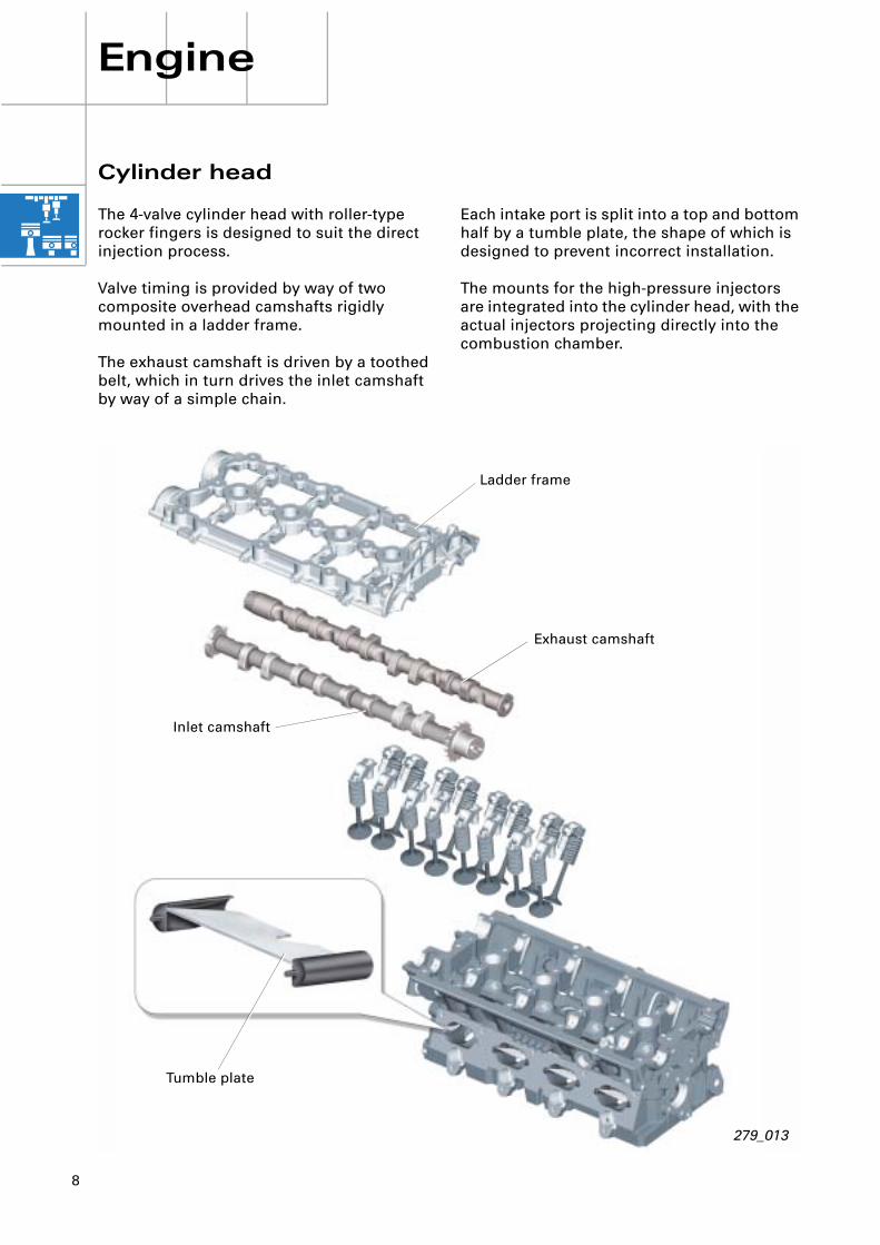
Oil circulation
The use of a 4-valve cylinder head with roller-type rocker fingers represents a major change in oil gallery design with respect to the 5-valve cylinder head with bucket tappets.Passing via the main oil gallery from the engine block, the oil enters the cylinder head between cylinders 3 and 4.
Oil pressure is applied to the hydraulic support elements and camshaft bearings by way of two oil ducts. The support elements are provided with a spray orifice for lubrication of the roller-type rocker fingers. Further along the oil ducts, oil pressure is applied to the rotary motor for camshaft adjustment.
8
279_013
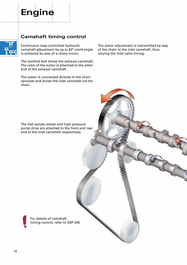
Exhaust camshaft
Ladder frame
Inlet camshaft
Tumble plate
Engine
Cylinder head
The 4-valve cylinder head with roller-type rocker fingers is designed to suit the direct injection process.
Valve timing is provided by way of two composite overhead camshafts rigidly mounted in a ladder frame.
The exhaust camshaft is driven by a toothed belt, which in turn drives the inlet camshaft by way of a simple chain.
Each intake port is split into a top and bottom half by a tumble plate, the shape of which is designed to prevent incorrect installation.
The mounts for the high-pressure injectors are integrated into the cylinder head, with the actual injectors projecting directly into the combustion chamber.

9
The valve gear takes the form of a "light valve gear" (i.e. with one valve spring only).
The valve cover is made of plastic and features a permanently attached elastomer seal.
279_015
Compositecamshaft
Roller-type rocker finger
279_016
Pressure control valve
Valve cover
Oil separator
The valves are actuated by two composite camshafts via roller-type rocker fingers which rest on hydraulic valve lifters.
The valve cover contains the pressure control valve for the crankcase breather and the internal oil separator.
10
Engine
The stator adjustment is transmitted by way of the chain to the inlet camshaft, thus varying the inlet valve timing.
Camshaft timing control
Continuous map-controlled hydraulic camshaft adjustment by up to 42° crank angle is achieved by way of a rotary motor.
The toothed belt drives the exhaust camshaft.The rotor of the motor is attached to the other end of the exhaust camshaft.
The stator is connected directly to the chain sprocket and drives the inlet camshaft via the chain.
The Hall sender wheel and high-pressure pump drive are attached to the front and rear end of the inlet camshaft respectively.
For details of camshafttiming control, refer to SSP 255
11
279_061
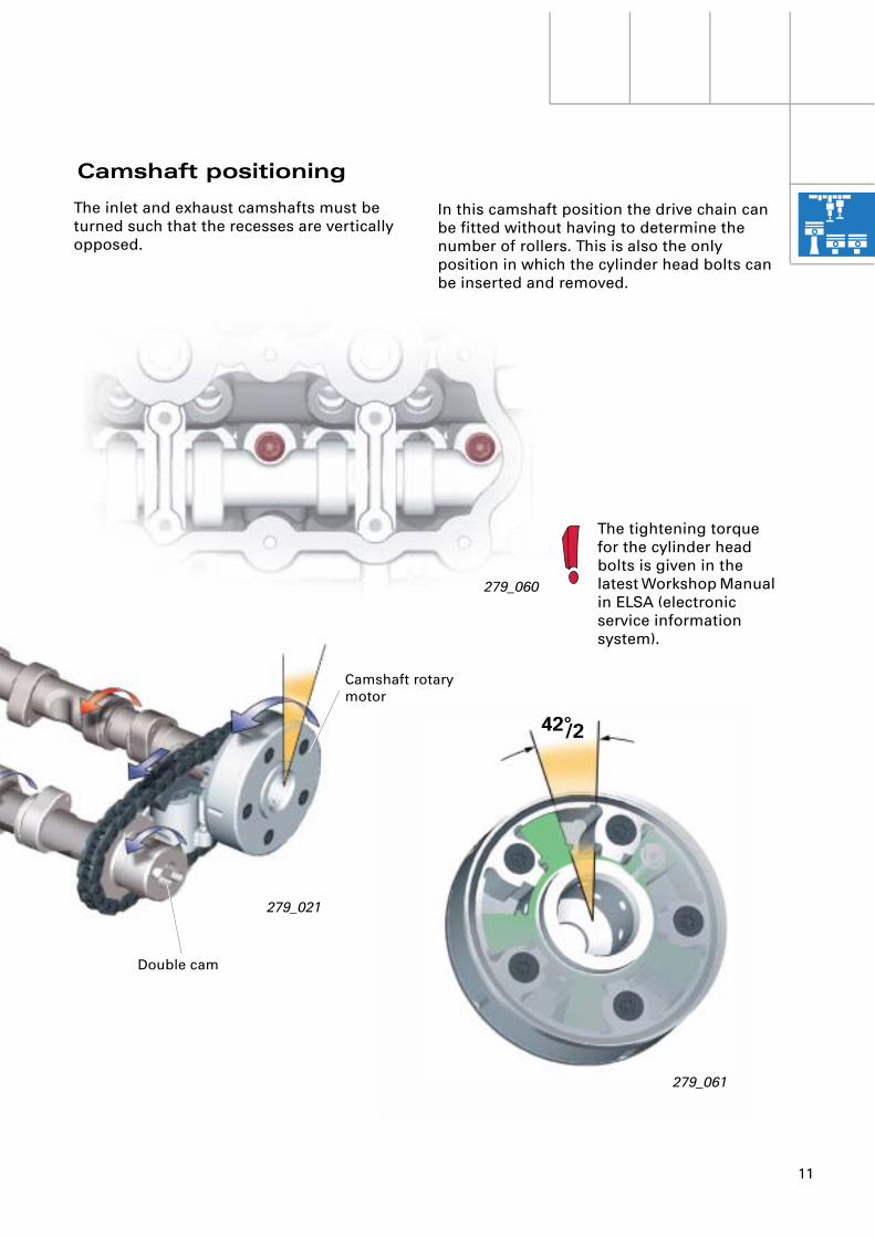
42°/2
279_021
Double cam
279_060
Camshaft rotary motor
The tightening torque for the cylinder head bolts is given in the latest Workshop Manual in ELSA (electronic service information system).
Camshaft positioning
In this camshaft position the drive chain can be fitted without having to determine the number of rollers. This is also the only position in which the cylinder head bolts can be inserted and removed.
The inlet and exhaust camshafts must be turned such that the recesses are vertically opposed.
12
Engine
279_017
Vacuumreservoir
279_018
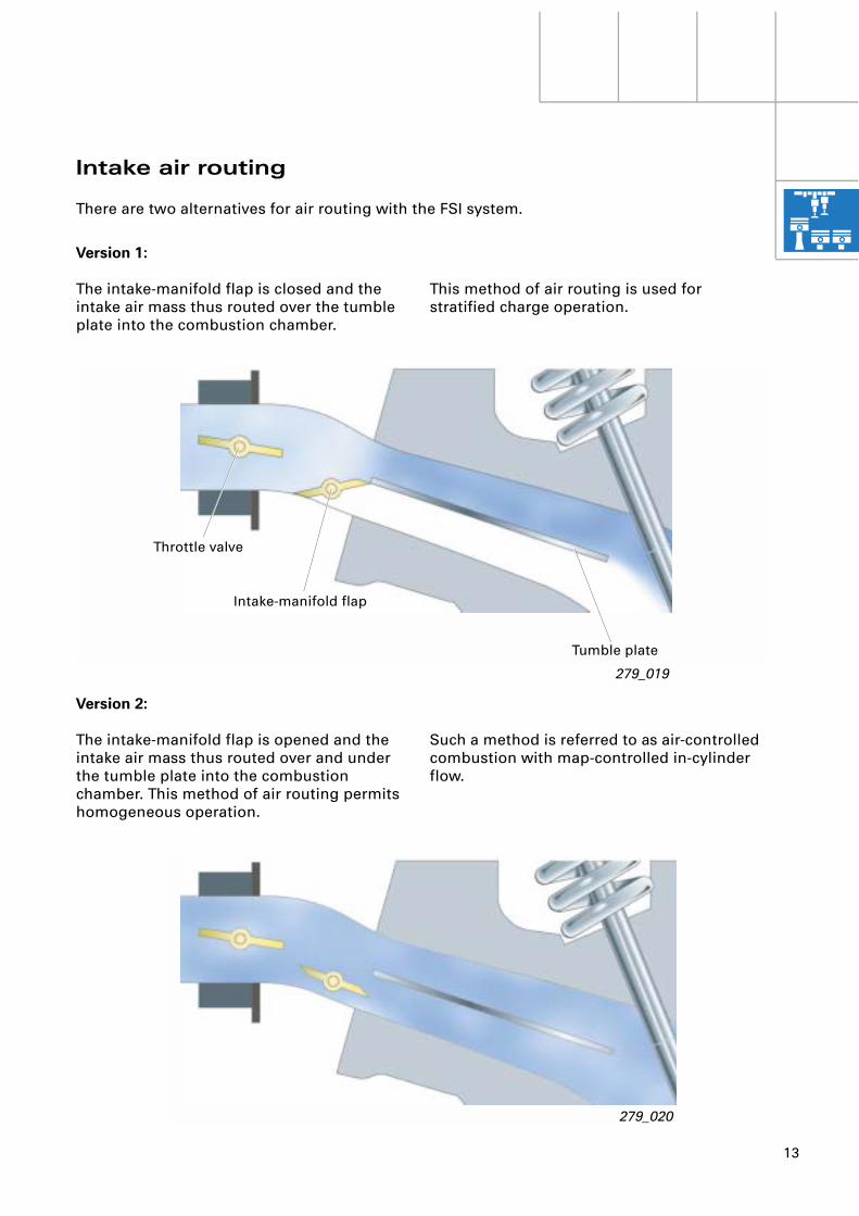
The position of the intake-manifold flaps influences mixture formation and thus emission values. Intake-manifold flap control is classified as an emission-specific system and is monitored by the EOBD.
The lower part of the intake manifold is bolted to the fuel rail.
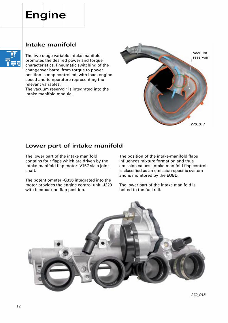
Intake manifold
The two-stage variable intake manifold promotes the desired power and torque characteristics. Pneumatic switching of the changeover barrel from torque to power position is map-controlled, with load, engine speed and temperature representing the relevant variables.The vacuum reservoir is integrated into the intake manifold module.
The lower part of the intake manifold contains four flaps which are driven by the intake-manifold flap motor -V157 via a joint shaft.
The potentiometer -G336 integrated into the motor provides the engine control unit -J220 with feedback on flap position.
Lower part of intake manifold
13
Version 1:
The intake-manifold flap is closed and the intake air mass thus routed over the tumble plate into the combustion chamber.
Version 2:
The intake-manifold flap is opened and the intake air mass thus routed over and under the tumble plate into the combustion chamber. This method of air routing permits homogeneous operation.
Throttle valve
Intake-manifold flap
Tumble plate
279_020
279_019
This method of air routing is used for stratified charge operation.
Such a method is referred to as air-controlled combustion with map-controlled in-cylinder flow.
Intake air routing
There are two alternatives for air routing with the FSI system.
14
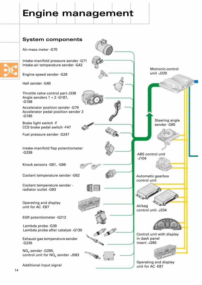
Motronic control unit -J220
ABS control unit -J104
Airbagcontrol unit -J234
Control unit with display in dash panelinsert -J285
Operating and displayunit for AC -E87
Automatic gearbox control unit
Steering angle sender -G85
Engine management
System components
Intake-manifold pressure sender -G71Intake-air temperature sender -G42
Throttle valve control part-J338Angle senders 1 + 2 -G187, -G188
Intake-manifold flap potentiometer -G336
Exhaust-gas temperature sender -G235
Air-mass meter -G70
Engine speed sender -G28
Hall sender -G40
Accelerator position sender -G79Accelerator pedal position sender 2 -G185
Brake light switch -FCCS brake pedal switch -F47
Fuel pressure sender -G247
Knock sensors -G61, -G66
Coolant temperature sender -G62
Coolant temperature sender - radiator outlet -G83
Operating and displayunit for AC -E87
EGR potentiometer -G212
Lambda probe -G39Lambda probe after catalyst -G130
NOx sender -G295,control unit for NOx sender -J583
Additional input signal
15
279_047
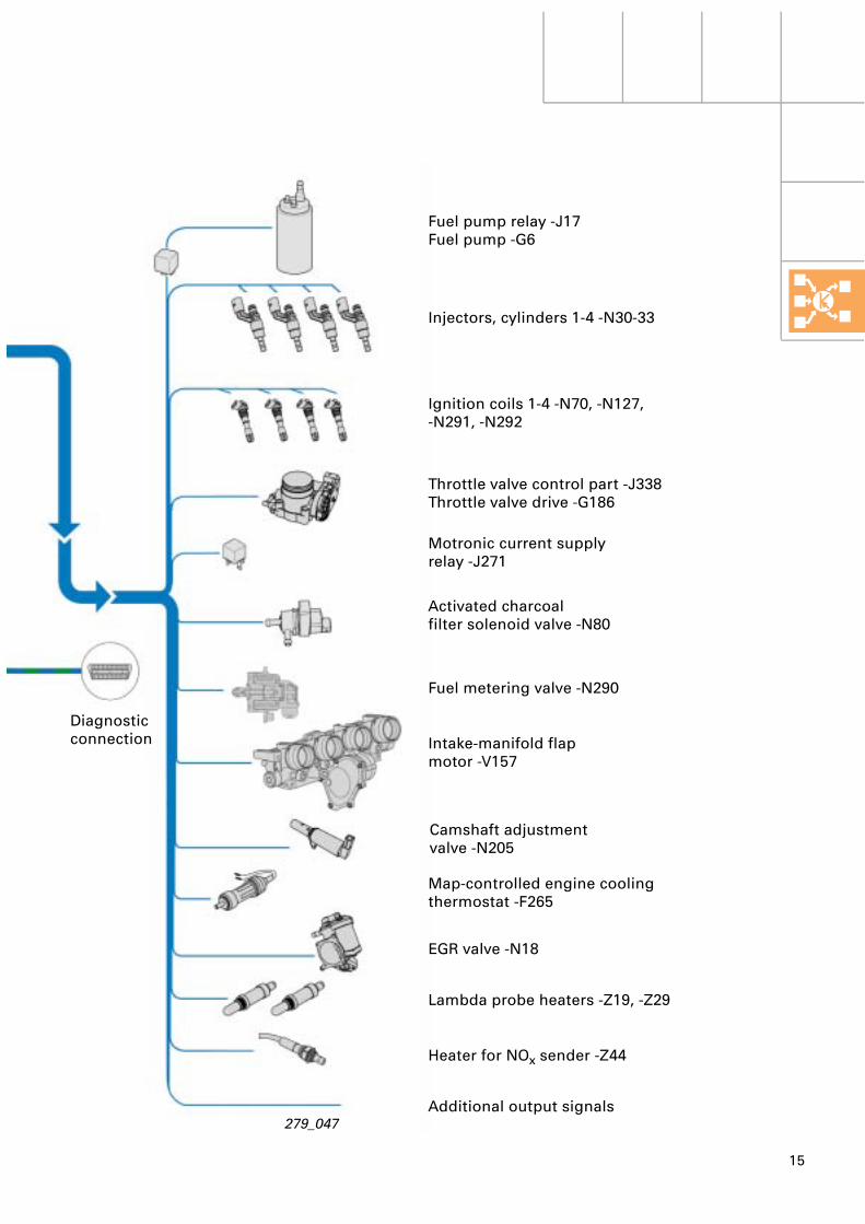
Diagnosticconnection
Camshaft adjustmentvalve -N205
Fuel metering valve -N290
Fuel pump relay -J17Fuel pump -G6
Injectors, cylinders 1-4 -N30-33
Ignition coils 1-4 -N70, -N127, -N291, -N292
Throttle valve control part -J338Throttle valve drive -G186
Activated charcoalfilter solenoid valve -N80
Map-controlled engine coolingthermostat -F265
EGR valve -N18
Lambda probe heaters -Z19, -Z29
Heater for NOx sender -Z44
Additional output signals
Motronic current supplyrelay -J271
Intake-manifold flapmotor -V157

16
Engine management
Engine control unit
Intake-air temperatureBrake light switchBrake pedal switchThrottle valve angleElectronic throttle warning lamp/infoDriver input torqueEmergency running programs(self-diagnosis info)Accelerator pedal positionCCS switch positionsCCS specified speedAltitude informationKickdown informationCompressor switch-offCompressor ON/OFFFuel consumptionCoolant temperatureClutch pedal switchIdling speed recognitionEngine speedACTUAL engine torquesImmobilizerCrash signalExhaust-gas temperature
Gearbox control unit
Adaption releaseIdle regulationCompressor switch-offSpecified idling speedSPECIFIED engine torqueEmergency running programs (self-diagnosis info)Gearshift active/not activeSelector lever positionConverter/gearbox protectionTorque converter clutch statusCurrent gear/target gear
ESP control unit
TCS requestSPECIFIED TCS intervention torqueBrake pedal statusESP interventionVehicle speedOverrun torque limiting function requestOverrun torque limiting function intervention torque
NOx sender
NOx saturation(for regeneration)
Dash panel insert
Self-diagnosis infoVehicle speedMileageCoolant temperatureOil temperatureImmobilizer
Steering angle sender
Steering wheel angle(used for pilot control of idling speed and for engine torque calculation based on power steering power requirement)
CAN low
CAN high
279_067
CAN bus interfaces
17
Four more modes of operation are available to round off the FSI concept.These modes of operation are contained in the reading measured value block function.
279_048
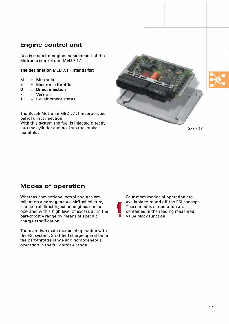
Engine control unit
Use is made for engine management of the Motronic control unit MED 7.1.1.
The designation MED 7.1.1 stands for:
M = MotronicE = Electronic throttleD = Direct injection7. = Version1.1 = Development status
The Bosch Motronic MED 7.1.1 incorporates petrol direct injection.With this system the fuel is injected directly into the cylinder and not into the intake manifold.
Modes of operation
Whereas conventional petrol engines are reliant on a homogeneous air/fuel mixture, lean petrol direct injection engines can be operated with a high level of excess air in the part-throttle range by means of specific charge stratification.
There are two main modes of operation with the FSI system: Stratified charge operation in the part-throttle range and homogeneous operation in the full-throttle range.
18
Engine management
279_025
279_024
279_049
High-pressure injector
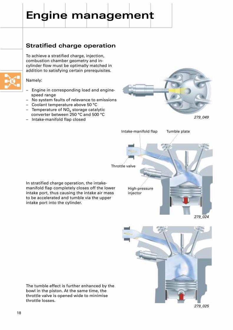
Throttle valve
Intake-manifold flap Tumble plate
Stratified charge operation
To achieve a stratified charge, injection, combustion chamber geometry and in-cylinder flow must be optimally matched in addition to satisfying certain prerequisites.
Namely:
– Engine in corresponding load and engine-speed range
– No system faults of relevance to emissions– Coolant temperature above 50 °C– Temperature of NOx storage catalytic
converter between 250 °C and 500 °C– Intake-manifold flap closed
In stratified charge operation, the intake-manifold flap completely closes off the lower intake port, thus causing the intake air mass to be accelerated and tumble via the upper intake port into the cylinder.
The tumble effect is further enhanced by the bowl in the piston. At the same time, the throttle valve is opened wide to minimise throttle losses.
19
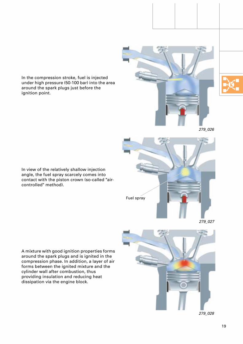
Fuel spray
279_026
279_027
279_028
In the compression stroke, fuel is injected under high pressure (50-100 bar) into the area around the spark plugs just before the ignition point.
In view of the relatively shallow injection angle, the fuel spray scarcely comes into contact with the piston crown (so-called "air-controlled" method).
A mixture with good ignition properties forms around the spark plugs and is ignited in the compression phase. In addition, a layer of air forms between the ignited mixture and the cylinder wall after combustion, thus providing insulation and reducing heat dissipation via the engine block.

20
Engine management
279_030
279_031
Homogeneous operation
In the upper load and engine-speed range, the intake-manifold flap is opened to enable the intake air mass to flow into the cylinder via the upper and lower intake port.
In contrast to stratified charge operation, fuel is not injected in the compression phase, but rather in the induction phase, producing a homogeneous charge (14.7:1) in the cylinder.
21
279_032
279_033
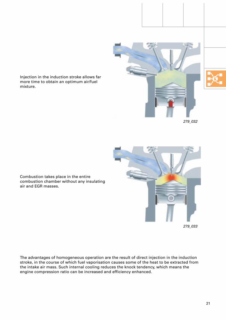
The advantages of homogeneous operation are the result of direct injection in the induction stroke, in the course of which fuel vaporisation causes some of the heat to be extracted from the intake air mass. Such internal cooling reduces the knock tendency, which means the engine compression ratio can be increased and efficiency enhanced.
Injection in the induction stroke allows far more time to obtain an optimum air/fuel mixture.
Combustion takes place in the entire combustion chamber without any insulating air and EGR masses.
22
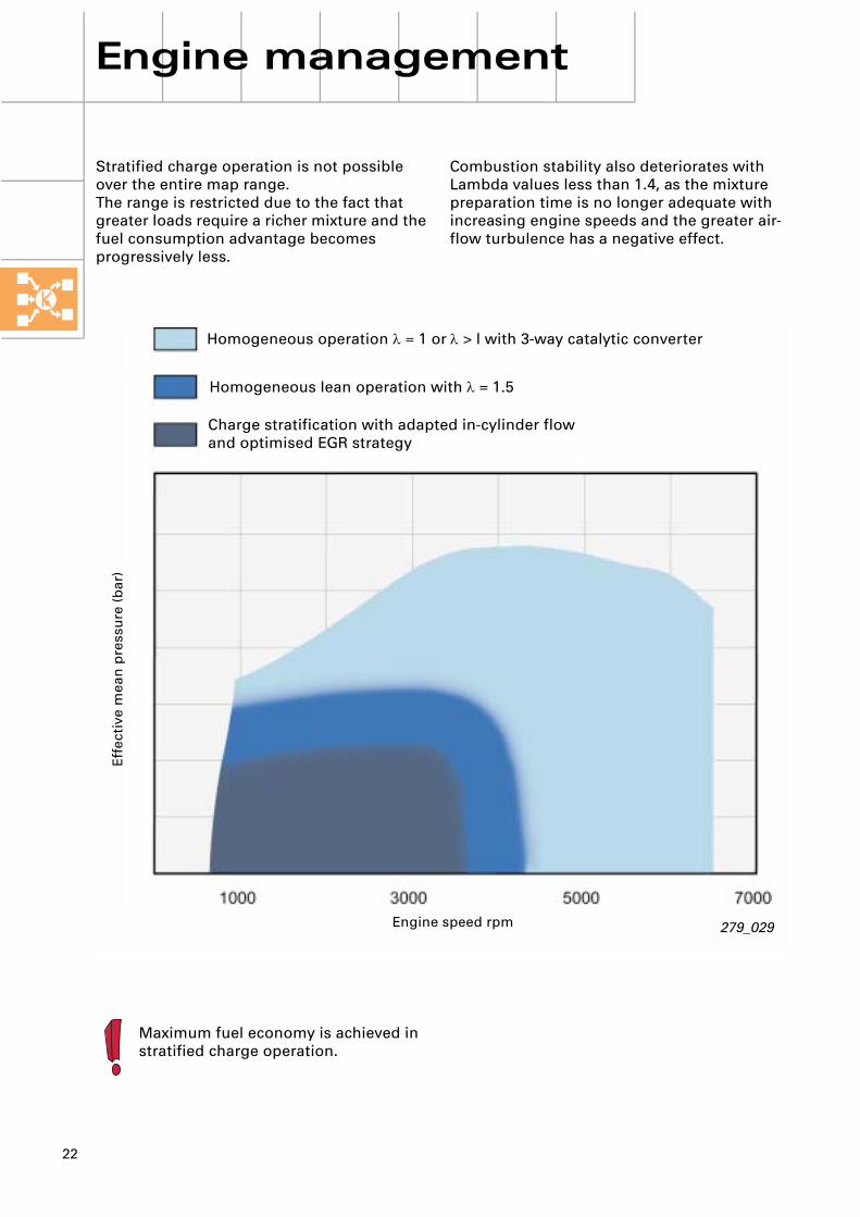
Stratified charge operation is not possible over the entire map range.The range is restricted due to the fact that greater loads require a richer mixture and the fuel consumption advantage becomes progressively less.
Maximum fuel economy is achieved in stratified charge operation.
Engine management
279_029
Effe
ctiv
e m
ean
pre
ssu
re (b
ar)
Engine speed rpm
Homogeneous operation λ = 1 or λ > l with 3-way catalytic converter
Homogeneous lean operation with λ = 1.5
Charge stratification with adapted in-cylinder flow and optimised EGR strategy
Combustion stability also deteriorates with Lambda values less than 1.4, as the mixture preparation time is no longer adequate with increasing engine speeds and the greater air-flow turbulence has a negative effect.
Self Study Programme Questionnaire
What is your position within the Dealership?Please quote name, telephone number and fax number for reply and queries.
......................................................................................................................................................
Are the descriptions and explanations readily comprehensible?YES NO Page/Section
......................................................................................................................................................
......................................................................................................................................................
Are the illustrations clear and adequate?YES NO Page/Fig. No.
......................................................................................................................................................
......................................................................................................................................................
......................................................................................................................................................
Is enough detail given on the subject matter relevant to your work?YES NO Page
......................................................................................................................................................
......................................................................................................................................................
......................................................................................................................................................
Do you consider anything to have been overlooked?NO YES Page/What?
......................................................................................................................................................
......................................................................................................................................................
......................................................................................................................................................
Should further items be added to this questionnaire?NO YES Which question(s)?
......................................................................................................................................................
......................................................................................................................................................
......................................................................................................................................................
Remarks/miscellaneous:............................................................................................................................................................................................................................................................................................................
Please submit your questionnaire to the following fax number:
++49/841 89 36 36 7
279
A note toall users:
This Self Study Programme is intended to familiarise readers with the 2.0 l 110 kW engine with petrol direct injection (FSI).
Your opinion matters to us.
That is why we would like you to give us your thoughts on and any suggestions for future Self Study Programmes. The following questionnaire is designed to help you do so.
Please make use of fax number 0049/841 89 36 36 7 for your suggestions.
Thank you for your assistance.
Your Service Technology TrainingTeam

23
Notes

24
Engine sub-systems
Fuel pressure sender -G247
High-pressure injector
Pressure relief valve
Fuel filter
Electric fuel pump -G6
Fuel system
The fuel system consists of a low and high-pressure section.
In the low-pressure system, the fuel is conveyed by an electric fuel pump at approx. 6 bar via the filter to the high-pressure pump.
The return flow from the high-pressure pump passes directly back to the tank.

25
Fuel metering valve -N290
Activated charcoal filter
Single-plunger high-pressure pump
approx. 40 - 110 bar
approx. 6 bar
ACF valve
No pressure
Low pressure approx. 6 bar
High pressure approx. 40 -110 bar
Double cam
279_034
In the high-pressure system, the fuel flows at approx. 40 – 110 bar (depending on load and engine speed) out of the single-plunger high-pressure pump into the fuel rail, from where it is distributed to the four high-pressure injectors.
The pressure relief valve is designed to protect the components subjected to high pressure and opens as of a pressure of > 120 bar.
When the pressure relief valve opens, the fuel flows into the supply pipe to the high-pressure pump.
26
Engine sub-systems
Fuel metering valve -N290
Pressure damper
279_035
279_037
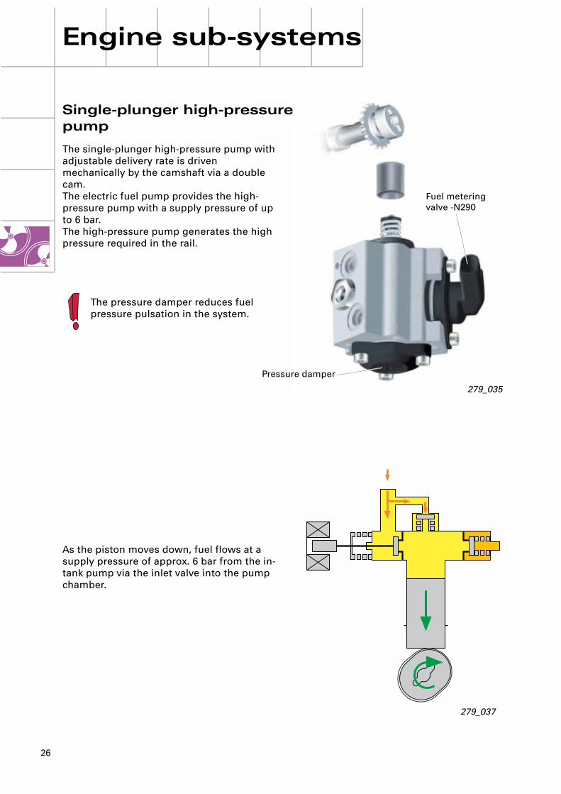
Single-plunger high-pressure pump
The single-plunger high-pressure pump with adjustable delivery rate is driven mechanically by the camshaft via a double cam. The electric fuel pump provides the high-pressure pump with a supply pressure of up to 6 bar. The high-pressure pump generates the high pressure required in the rail.
The pressure damper reduces fuel pressure pulsation in the system.
As the piston moves down, fuel flows at a supply pressure of approx. 6 bar from the in-tank pump via the inlet valve into the pump chamber.

27
279_038
279_039
As the piston moves up, the fuel is compressed and conveyed into the fuel rail on exceeding the prevailing rail pressure. Located between pump chamber and fuel inlet is the switchable fuel metering valve.
If the fuel metering valve opens prior to completion of the delivery stroke, the pressure in the pump chamber is dissipated and the fuel flows back into the fuel inlet. A non-return valve between pump chamber and fuel rail stops the rail pressure decreasing when the fuel metering valve opens.
To regulate the delivery rate, the fuel metering valve is closed as of pump cam BDC position until a certain stroke is reached. Once the necessary rail pressure has been attained, the fuel metering valve opens to prevent any further increase in pressure in the rail.
28
279_040
Fuel metering valve -N290
Armature
High-pressure plunger
Pump chamber
Solenoid
Valve needle
Pressure damper
Fuelinlet
High-pressureconnection
Engine sub-systems
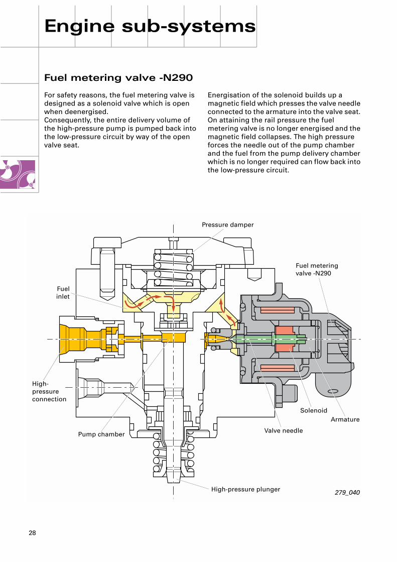
Energisation of the solenoid builds up a magnetic field which presses the valve needle connected to the armature into the valve seat. On attaining the rail pressure the fuel metering valve is no longer energised and the magnetic field collapses. The high pressure forces the needle out of the pump chamber and the fuel from the pump delivery chamber which is no longer required can flow back into the low-pressure circuit.
Fuel metering valve -N290
For safety reasons, the fuel metering valve is designed as a solenoid valve which is open when deenergised.Consequently, the entire delivery volume of the high-pressure pump is pumped back into the low-pressure circuit by way of the open valve seat.
29
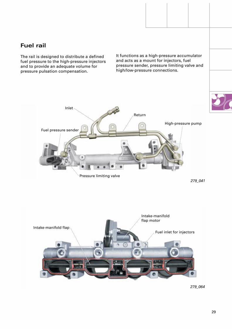
279_041
Inlet
Fuel pressure sender
Return
High-pressure pump
Pressure limiting valve
279_064
Intake-manifoldflap motor
Fuel inlet for injectorsIntake-manifold flap
Fuel rail
The rail is designed to distribute a defined fuel pressure to the high-pressure injectors and to provide an adequate volume for pressure pulsation compensation.
It functions as a high-pressure accumulator and acts as a mount for injectors, fuel pressure sender, pressure limiting valve and high/low-pressure connections.

30
Engine sub-systems
4,75 V4,65 V4,50 V
0,50 V0,30 V
0,25 V
140 bar
5,00 V
279_043
Output voltage
Senderdefective
Minimum pressure
Senderdefective
Maximum pressure
Pressur
279_042
Housing Connector
ASIC
PC board
Contact link
Sender element
Pressure connection
Spacer
Fuel pressure sender -G247
Within the overall system, the function of the fuel pressure sender is to measure the fuel pressure in the rail. The pressure applied is relayed to the engine control unit as a voltage quantity and used for fuel pressure control.
The evaluation electronics integrated into the sender are supplied with 5 V.With increasing pressure, the resistance drops and signal voltage rises.
The pressure sender characteristic curve illustrated shows signal output voltage [V] as afunction of pressure [MPa].
31
N30
N31
N32
N33
J 220
279_050
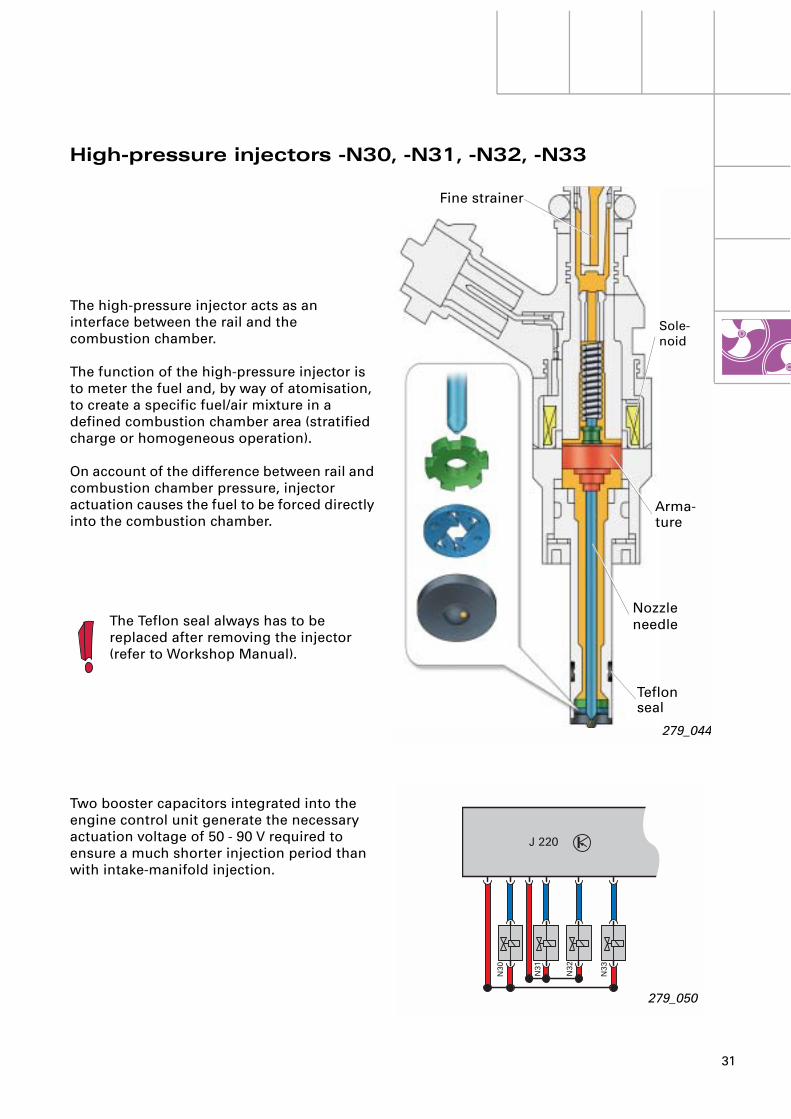
The high-pressure injector acts as an interface between the rail and the combustion chamber.
The function of the high-pressure injector is to meter the fuel and, by way of atomisation, to create a specific fuel/air mixture in a defined combustion chamber area (stratified charge or homogeneous operation).
On account of the difference between rail and combustion chamber pressure, injector actuation causes the fuel to be forced directly into the combustion chamber.
The Teflon seal always has to be replaced after removing the injector(refer to Workshop Manual).
Two booster capacitors integrated into the engine control unit generate the necessary actuation voltage of 50 - 90 V required to ensure a much shorter injection period than with intake-manifold injection.
High-pressure injectors -N30, -N31, -N32, -N33
Nozzle needle
279_044
Teflon seal
Sole-noid
Arma-ture
Fine strainer
32
Engine sub-systems
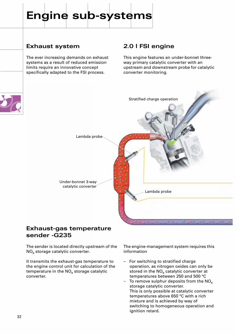
Stratified charge operation
Lambda probe
Lambda probe
Under-bonnet 3-waycatalytic converter
Exhaust system
The ever increasing demands on exhaust systems as a result of reduced emission limits require an innovative concept specifically adapted to the FSI process.
Exhaust-gas temperaturesender -G235
The sender is located directly upstream of the NOx storage catalytic converter.
It transmits the exhaust-gas temperature to the engine control unit for calculation of the temperature in the NOx storage catalytic converter.
2.0 l FSI engine
This engine features an under-bonnet three-way primary catalytic converter with an upstream and downstream probe for catalytic converter monitoring.
The engine-management system requires this information
– For switching to stratified charge operation, as nitrogen oxides can only be stored in the NOx catalytic converter at temperatures between 250 and 500 °C
– To remove sulphur deposits from the NOx storage catalytic converter. This is only possible at catalytic converter temperatures above 650 °C with a rich mixture and is achieved by way of switching to homogeneous operation and ignition retard.

33
NOx sender
Engine control unit
CAN wire
Control unit
NOx storage catalytic converter
Temperature sender
CO = Carbon monoxide
NOx = Nitrogen oxides
HC = Hydrocarbons
279_051
Exhaust gas treatment system
With a lean mixture composition, the conven-tional three-way catalytic converter exhibits a high conversion rate for CO and HC on account of the high residual oxygen content of the exhaust gas. The NOx conversion rate drops however if CO and HC concentrations are too low.
Use is made of the NOx storage catalytic converter to reduce the increased NOx component in lean operation (stratified charge operation).
NOx storage catalytic converter
The design of this converter corresponds to that of the three-way catalytic converter.The wash coat is however additionally provided with barium oxide to permit buffer storage of nitrogen oxides at temperatures between 250 and 500 °C through nitrate formation.
In addition to the desired nitrate formation, the sulphur contained in the fuel is always stored as well.
The storage capacity is however limited. The engine control unit is informed of saturation by the NOx sender and the engine-management system then takes appropriate action to regenerate the NOx storage catalytic converter.

34
Engine sub-systems
279_062
app
rox.
2 s
ec.
Stratified charge operation
Homogeneous operation λ < 1
Stratified charge operation
Regeneration phases
These are regulated by the engine control unit and are designed to extract the nitrogen oxides and sulphur. In this process, nitrogen oxides are converted into non-toxic nitrogen and sulphur into sulphur dioxide.
Nitrogen oxide regeneration
This causes the temperature of the NOx storage catalytic converter to increase. The nitrates formed thus become unstable and decompose under reducing ambient conditions.
The nitrogen oxides are converted into harmless nitrogen. The storage catalytic converter is thus emptied and the cycle recommences.
This takes place as soon as the concentration in the NOx storage catalytic converter exceeds the level specified in the engine control unit.
The engine control unit effects switching from stratified charge to homogeneous operation.
60-9
0 se
c.
35
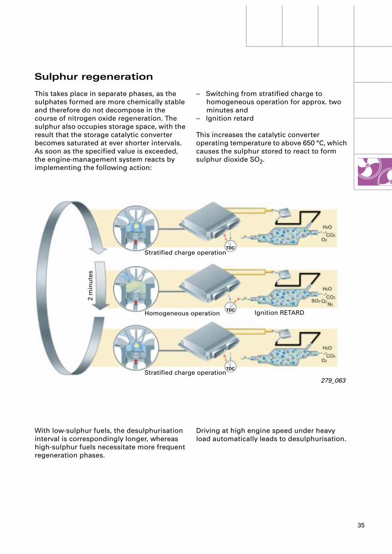
Stratified charge operation
Homogeneous operation
Stratified charge operation
Ignition RETARD
2 m
inu
tes
279_063
TDC
TDC
TDC
Sulphur regeneration
– Switching from stratified charge to homogeneous operation for approx. two minutes and
– Ignition retard
This increases the catalytic converter operating temperature to above 650 °C, which causes the sulphur stored to react to form sulphur dioxide SO2.
Driving at high engine speed under heavy load automatically leads to desulphurisation.
This takes place in separate phases, as the sulphates formed are more chemically stable and therefore do not decompose in the course of nitrogen oxide regeneration. The sulphur also occupies storage space, with the result that the storage catalytic converter becomes saturated at ever shorter intervals. As soon as the specified value is exceeded, the engine-management system reacts by implementing the following action:
With low-sulphur fuels, the desulphurisation interval is correspondingly longer, whereas high-sulphur fuels necessitate more frequent regeneration phases.
36
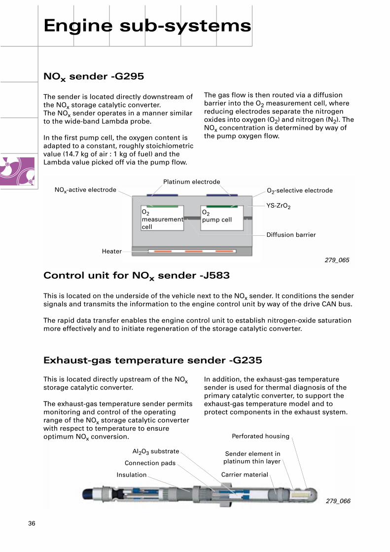
279_066
Connection pads
Insulation Carrier material
Sender element inplatinum thin layer
Al2O3 substrate
Perforated housing
Engine sub-systems
279_065
NOx-active electrode O2-selective electrodePlatinum electrode
YS-ZrO2
Diffusion barrier
Heater
O2measurement cell
O2pump cell
NOx sender -G295
The sender is located directly downstream of the NOx storage catalytic converter.The NOx sender operates in a manner similar to the wide-band Lambda probe.
In the first pump cell, the oxygen content is adapted to a constant, roughly stoichiometric value (14.7 kg of air : 1 kg of fuel) and the Lambda value picked off via the pump flow.
Control unit for NOx sender -J583
This is located on the underside of the vehicle next to the NOx sender. It conditions the sender signals and transmits the information to the engine control unit by way of the drive CAN bus.
The rapid data transfer enables the engine control unit to establish nitrogen-oxide saturation more effectively and to initiate regeneration of the storage catalytic converter.
Exhaust-gas temperature sender -G235
The gas flow is then routed via a diffusion barrier into the O2 measurement cell, where reducing electrodes separate the nitrogen oxides into oxygen (O2) and nitrogen (N2). The NOx concentration is determined by way of the pump oxygen flow.
In addition, the exhaust-gas temperature sender is used for thermal diagnosis of the primary catalytic converter, to support the exhaust-gas temperature model and to protect components in the exhaust system.
This is located directly upstream of the NOx storage catalytic converter.
The exhaust-gas temperature sender permits monitoring and control of the operating range of the NOx storage catalytic converter with respect to temperature to ensure optimum NOx conversion.
37
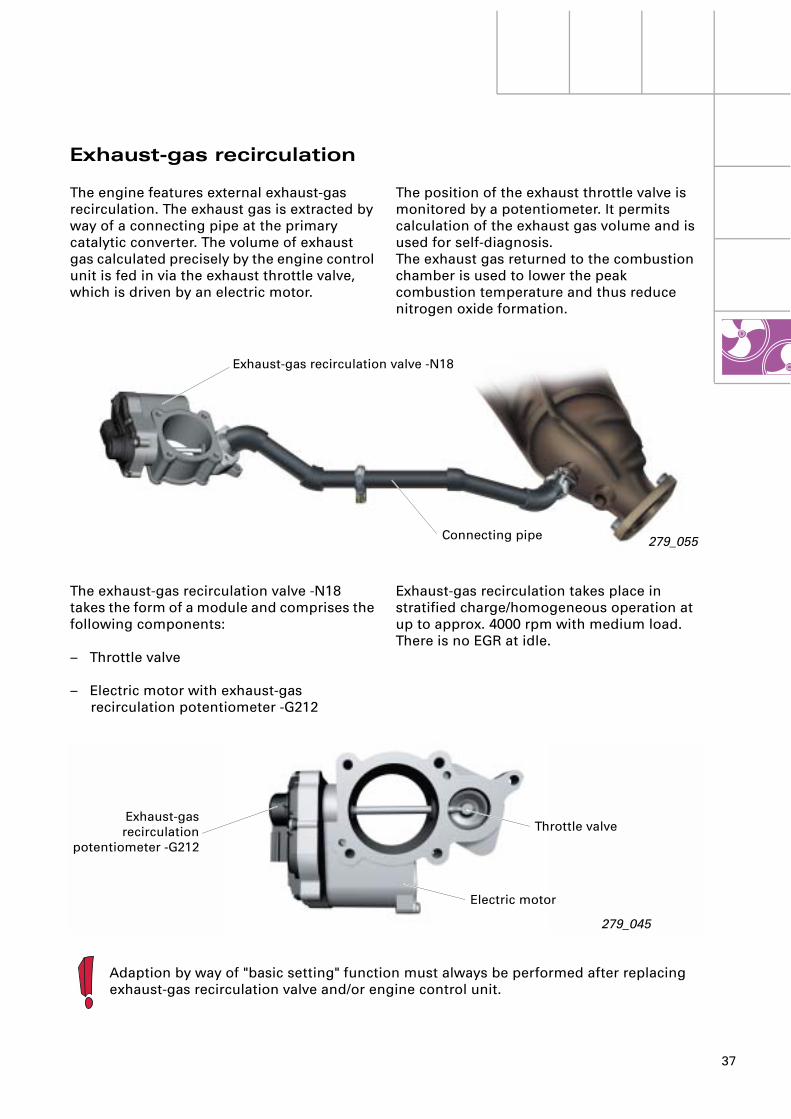
279_055Connecting pipe
Exhaust-gas recirculation valve -N18
Electric motor
Throttle valve
279_045
Exhaust-gasrecirculation
potentiometer -G212
Adaption by way of "basic setting" function must always be performed after replacing exhaust-gas recirculation valve and/or engine control unit.
The position of the exhaust throttle valve is monitored by a potentiometer. It permits calculation of the exhaust gas volume and is used for self-diagnosis.The exhaust gas returned to the combustion chamber is used to lower the peak combustion temperature and thus reduce nitrogen oxide formation.
Exhaust-gas recirculation takes place in stratified charge/homogeneous operation at up to approx. 4000 rpm with medium load.There is no EGR at idle.
Exhaust-gas recirculation
The engine features external exhaust-gas recirculation. The exhaust gas is extracted by way of a connecting pipe at the primary catalytic converter. The volume of exhaust gas calculated precisely by the engine control unit is fed in via the exhaust throttle valve, which is driven by an electric motor.
The exhaust-gas recirculation valve -N18 takes the form of a module and comprises the following components:
– Throttle valve
– Electric motor with exhaust-gas recirculation potentiometer -G212
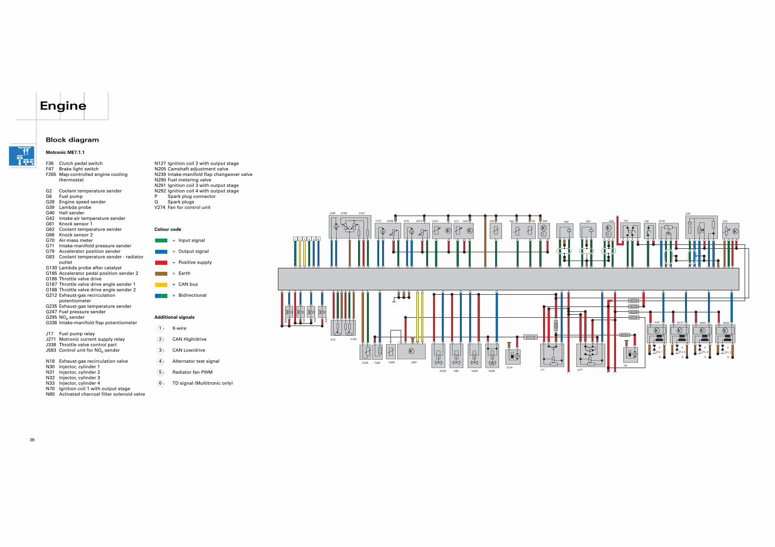
N127 Ignition coil 2 with output stageN205 Camshaft adjustment valveN239 Intake-manifold flap changeover valveN290 Fuel metering valveN291 Ignition coil 3 with output stageN292 Ignition coil 4 with output stageP Spark plug connectorQ Spark plugsV274 Fan for control unit
Colour code
= Input signal
= Output signal
= Positive supply
= Earth
= CAN bus
= Bidirectional
Additional signals
K-wire
CAN High/drive
CAN Low/drive
Alternator test signal
Radiator fan PWM
TD signal (Multitronic only)
1
2
3
4
5
6
G40G62G83 G2G42G212 G66G71G247 G28G61
N30
N31
N32
N33
M
M
N18
J338
M
V157 F47 F36 G130
G39
G70
ZYL 2ZYL 4ZYL 3ZYL 1M
G6
M
V274N205N290N80N239
J583G295F265G235
G185
1 2 4 5 63
P
Q
P
Q
P
Q
P
Q
N291N127N70 N292
J271J17
G188 G187
G336
G79
Engine
38
Block diagram
Motronic ME7.1.1
F36 Clutch pedal switchF47 Brake light switchF265 Map-controlled engine cooling
thermostat
G2 Coolant temperature senderG6 Fuel pump G28 Engine speed senderG39 Lambda probeG40 Hall senderG42 Intake-air temperature senderG61 Knock sensor 1G62 Coolant temperature senderG66 Knock sensor 2G70 Air-mass meterG71 Intake-manifold pressure senderG79 Accelerator position senderG83 Coolant temperature sender - radiator
outletG130 Lambda probe after catalystG185 Accelerator pedal position sender 2G186 Throttle valve drive G187 Throttle valve drive angle sender 1G188 Throttle valve drive angle sender 2G212 Exhaust-gas recirculation
potentiometerG235 Exhaust-gas temperature senderG247 Fuel pressure senderG295 NOx senderG336 Intake-manifold flap potentiometer
J17 Fuel pump relayJ271 Motronic current supply relayJ338 Throttle valve control partJ583 Control unit for NOx sender
N18 Exhaust-gas recirculation valveN30 Injector, cylinder 1N31 Injector, cylinder 2N32 Injector, cylinder 3N33 Injector, cylinder 4N70 Ignition coil 1 with output stageN80 Activated charcoal filter solenoid valve

39
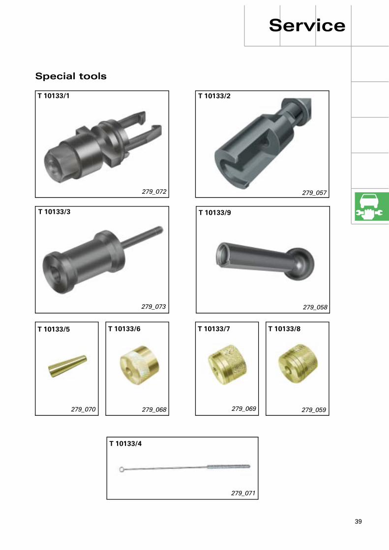
Service
Special tools
279_072
279_070
T 10133/1
279_057
T 10133/2
279_073
T 10133/3
T 10133/4
279_071
T 10133/5
279_068
T 10133/6
279_069
T 10133/7
279_058
T 10133/9
T 10133/8
279_059

40
Notes


27
9
Service.
279
Self Study Programme 279
For internal use only
All rights reserved. Subject to technical modification.AUDI AGDepartment I/VK-35D-85045 IngolstadtFax 0841/89-36367240.2810.98.20Technical status as at 12/01Printed in Germany
The 2.0 l 110 kW engine with petrol direct injection (FSI)