thank you for attending today’s webinar - lesman thank you for attending today’s webinar: asme...
TRANSCRIPT
www.Lesman.com/train/
Thank You for Attending Today’s Webinar:
ASME Boiler Code Requirements for Drum Level
Your HostMike DeLacluysePresidentLesman Instrument [email protected]
Featured SpeakerJim KolbusProduct Manager, Boiler [email protected]
Follow the Conversation LIVE @Lesman_Inst #LesmanWebinar

ASME Requirements for Boiler Water Level Instrumentation
August 24, 2017Presented by:
Clark-Reliance & Lesman
Topics• Define the types of Water Gage Glasses
and Remote Water Level Indicators
• ASME Code Section I Requirements for Drum Level Instrumentation (Steam Boilers that operate > 15 PSI)
• Positioning Level instrumentation Correctly
• Low Water Cutouts
• Section VII Recommended Proper Care for Power Boilers
• Common Code Violations
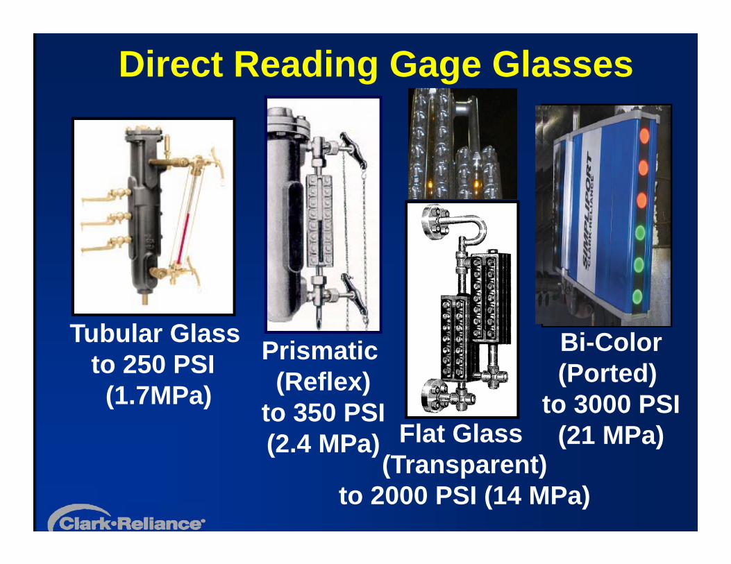
Direct Reading Gage Glasses
Tubular Glassto 250 PSI(1.7MPa)
Bi-Color(Ported)
to 3000 PSI(21 MPa)Flat Glass
(Transparent)to 2000 PSI (14 MPa)
Prismatic (Reflex)
to 350 PSI(2.4 MPa)
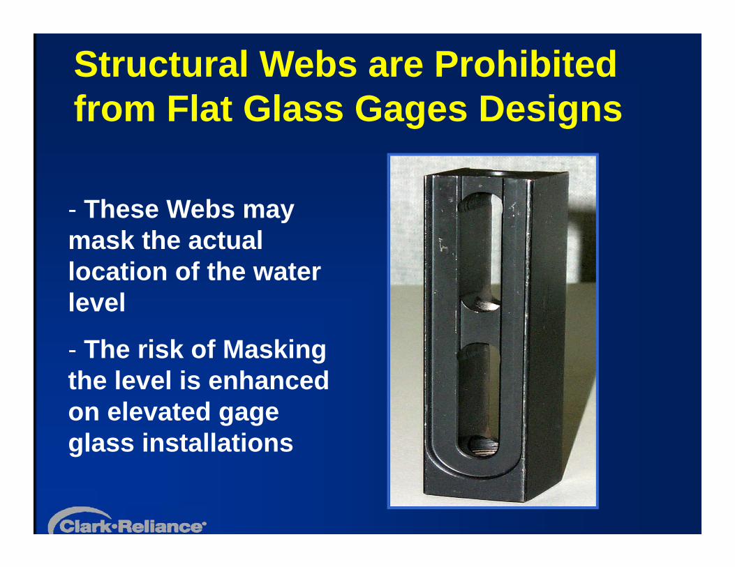
Structural Webs are Prohibited from Flat Glass Gages Designs
- These Webs may mask the actual location of the water level
- The risk of Masking the level is enhanced on elevated gage glass installations

Bi-Color Water Gage Principle of OperationWater shows GREEN Steam shows RED.
Bi-Color Gages must be outfitted with an illuminator to be Code Compliant
(Light refracts differently through water than steam with glasses on specific angles)

Remote (Indirect) Level Indicator Technologies
Differential Pressure
Conductivity
Magnetic
Guided Wave

Electrolev Column
Control Unit with Smart Probe Modules
Conductivity Type Remote Level Indicator System Components
Indicator
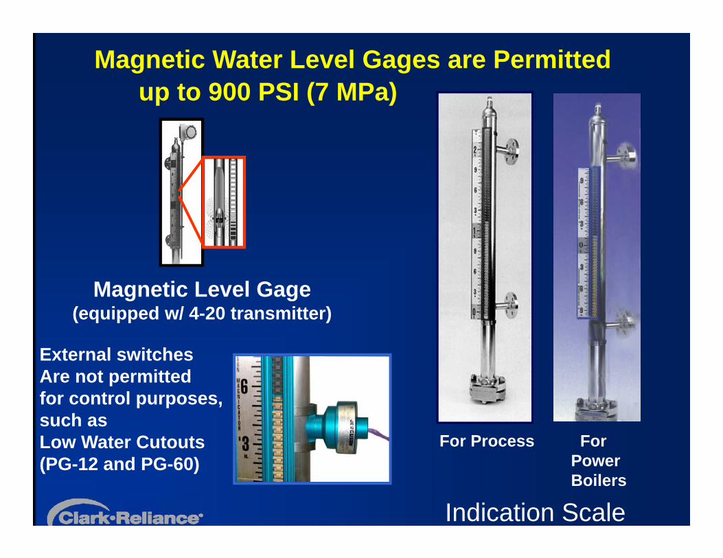
Magnetic Water Level Gages are Permitted up to 900 PSI (7 MPa)
Magnetic Level Gage(equipped w/ 4-20 transmitter)
For Process For Power Boilers
Indication Scale
External switches Are not permittedfor control purposes, such as Low Water Cutouts(PG-12 and PG-60)
Code Issues and Concerns for the Use of Magnetic Level Gages on Boiler Drums Acceptable as an acceptable Indirect Reading for applications Gage
up to 900 PSI (Ref: PG12.2)
The Indication Scale must follow ASME guidelines (Ref: PG-60.3.2 &PG60.3.3)
May not be used to support a water Gage glass, due to prohibition of stainless steel construction for water columns. Ref: PG-12.3
No accessories are permitted to be attached for control purposes(No Trip Switches). This device must be used for indication only.Ref: PG-60.1.1.4
NOTE: The use of a Magnetic Level Gage does not replace the Code requirement for a Direct Reading Water Gage Glass on any Power Boiler Drum designed to meet the ASME Section I Boiler Code
Concerns for the Application of Magnetic Water Gages on Boiler Drums The float design is based on the operating
conditions(customer specified), not the boiler design conditions. Therefore, if the boiler is operated at a pressure lower than the planned operating pressure, the Magnetic Gage reading will be higher than the actual drum level.
If the user has poor water quality, the potential exists for iron particles to attach onto the float. This will result in a heavier float, with an inaccurate level reading.
Remote (Indirect) Level Indicators• All Differential Pressure and Guided Wave
type Indirect Level Indication instruments must be installed and programmed to the manufactures instructions to prevent indication errors.
• Precautions must be taken to prevent adverse effects from freezing conditions on the level sensing components
• Insulation on all piping is recommended, except on the Condensate Pots for DP transmitters. Install cages or guards to protect personnel, if service area is confined
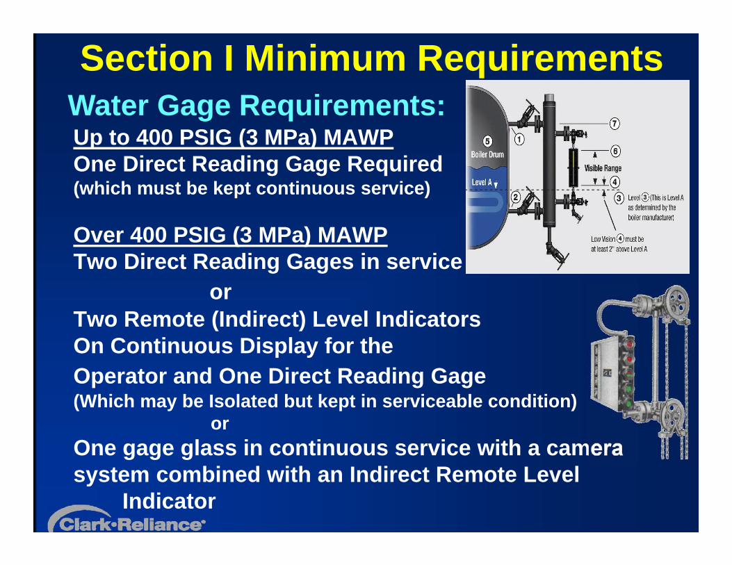
Section I Minimum Requirements
Up to 400 PSIG (3 MPa) MAWPOne Direct Reading Gage Required(which must be kept continuous service)
Over 400 PSIG (3 MPa) MAWPTwo Direct Reading Gages in service
orTwo Remote (Indirect) Level IndicatorsOn Continuous Display for the Operator and One Direct Reading Gage(Which may be Isolated but kept in serviceable condition)
or One gage glass in continuous service with a camera system combined with an Indirect Remote Level
Indicator
Water Gage Requirements:
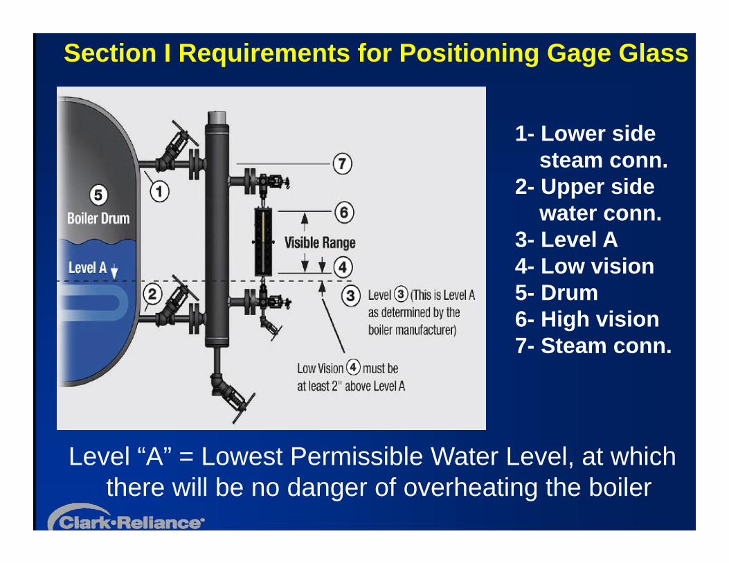
Section I Requirements for Positioning Gage Glass
Level “A” = Lowest Permissible Water Level, at which there will be no danger of overheating the boiler
1- Lower side steam conn.
2- Upper side water conn.
3- Level A4- Low vision5- Drum6- High vision7- Steam conn.
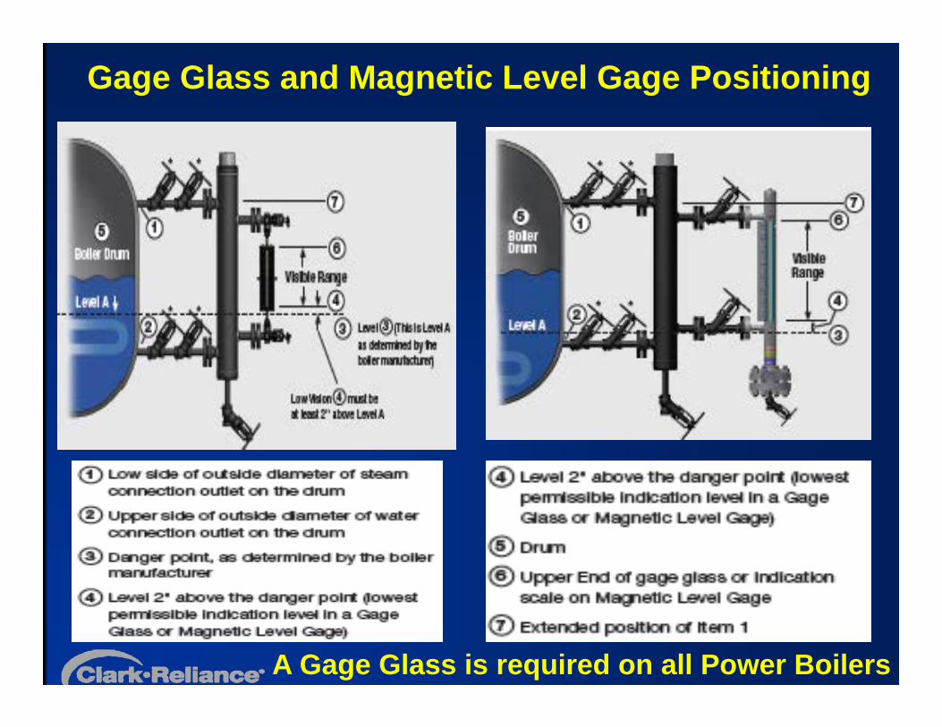
Gage Glass and Magnetic Level Gage Positioning
A Gage Glass is required on all Power Boilers
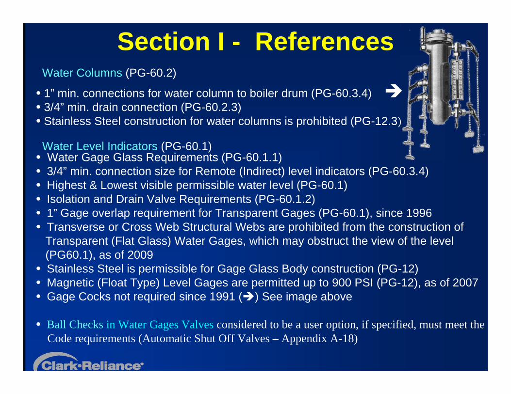
Section I - ReferencesWater Columns (PG-60.2)
1” min. connections for water column to boiler drum (PG-60.3.4) 3/4” min. drain connection (PG-60.2.3) Stainless Steel construction for water columns is prohibited (PG-12.3)
Water Level Indicators (PG-60.1) Water Gage Glass Requirements (PG-60.1.1) 3/4” min. connection size for Remote (Indirect) level indicators (PG-60.3.4) Highest & Lowest visible permissible water level (PG-60.1) Isolation and Drain Valve Requirements (PG-60.1.2) 1” Gage overlap requirement for Transparent Gages (PG-60.1), since 1996 Transverse or Cross Web Structural Webs are prohibited from the construction of
Transparent (Flat Glass) Water Gages, which may obstruct the view of the level(PG60.1), as of 2009 Stainless Steel is permissible for Gage Glass Body construction (PG-12) Magnetic (Float Type) Level Gages are permitted up to 900 PSI (PG-12), as of 2007 Gage Cocks not required since 1991 () See image above
Ball Checks in Water Gages Valves considered to be a user option, if specified, must meet the Code requirements (Automatic Shut Off Valves – Appendix A-18)
Section I Valve Requirements• Isolation valves installed between the drum and
a water column are optional and when installed they must be locked open, to prevent unauthorized use.
• Isolation (shut off) and drain valves must be installed for any level indicating instrument (Ref: PG-60.1.2)
• Install drain piping to a safe point of discharge for safety

Always Install Chain Operators for
Operator and Plant Safety
PG.60.1.2 requires a means to operate the isolation valves from the operating floor or platform
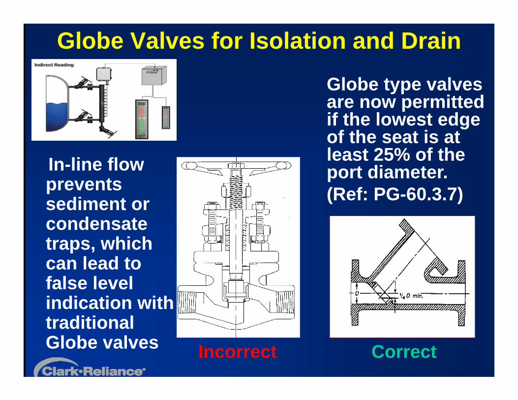
Globe Valves for Isolation and Drain
In-line flow prevents sediment or condensate traps, which can lead to false level indication with traditional Globe valves CorrectIncorrect
Globe type valves are now permitted if the lowest edge of the seat is at least 25% of the port diameter.(Ref: PG-60.3.7)
Low Water Cutouts – ASME CSD-1 (Controls and Safety Devices for Automatically Fired Boilers)
Section CW-140 requires two separate devices
• The two devices must be in separate chambers and connected to separate water nozzles from the drum, but they may connected to the same steam nozzle. Note: One of the devices may be inserted directly into the boiler.
• Minimum pipe connection size is 1” with a vertical drain at least ¾ NPS
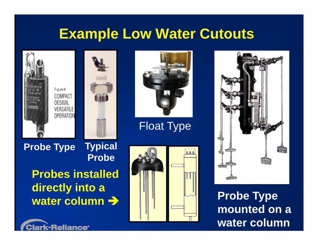
Example Low Water Cutouts
Typical Probe
Probe Type
Probe Type mounted on a water column
Probes installed directly into a water column
Float Type

Common Code Violations and Concerns
• Inoperable or Contaminated Water Gages • Missing Illumination from Ported Gages• Missing Water Gage Glasses• Inadequate display of remote Level
Indicators in the control room combined with isolated gages
• Poor Maintenance Practices
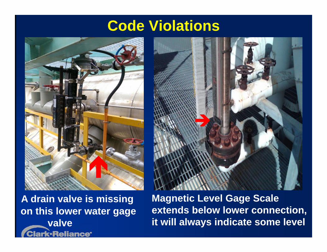
Code Violations
A drain valve is missing on this lower water gage
valve
Magnetic Level Gage Scale extends below lower connection, it will always indicate some level
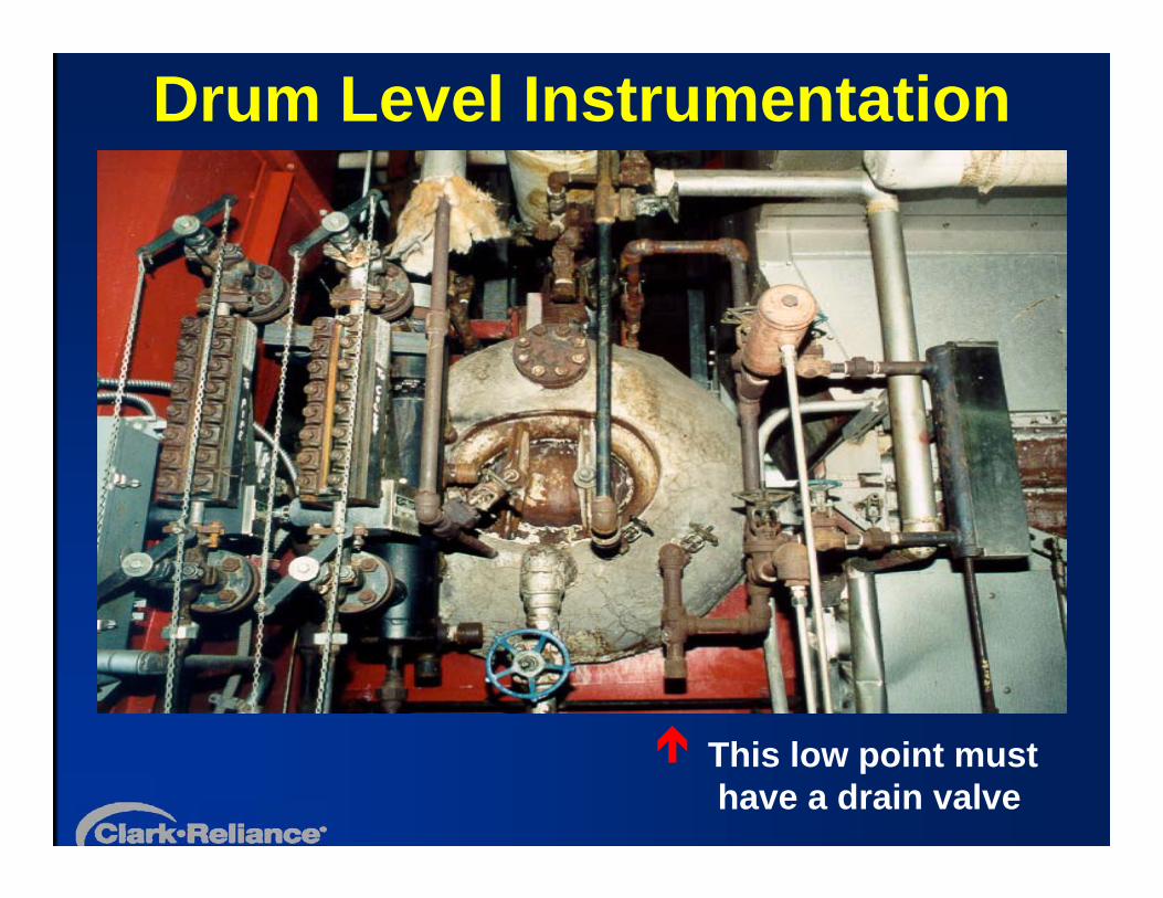
Drum Level Instrumentation
This low point must have a drain valve
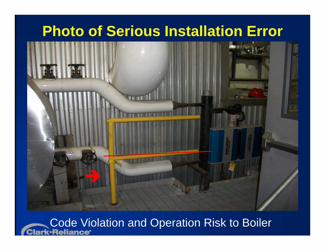
Photo of Serious Installation Error
Code Violation and Operation Risk to Boiler
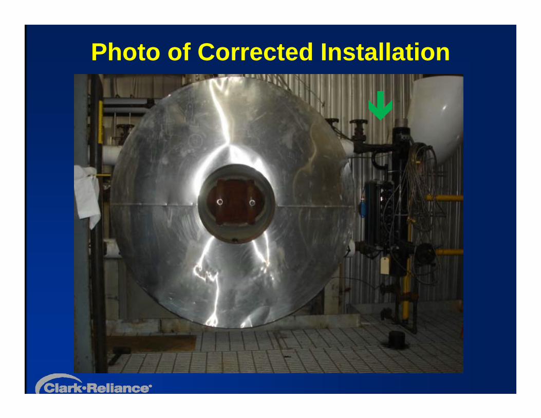
Photo of Corrected Installation
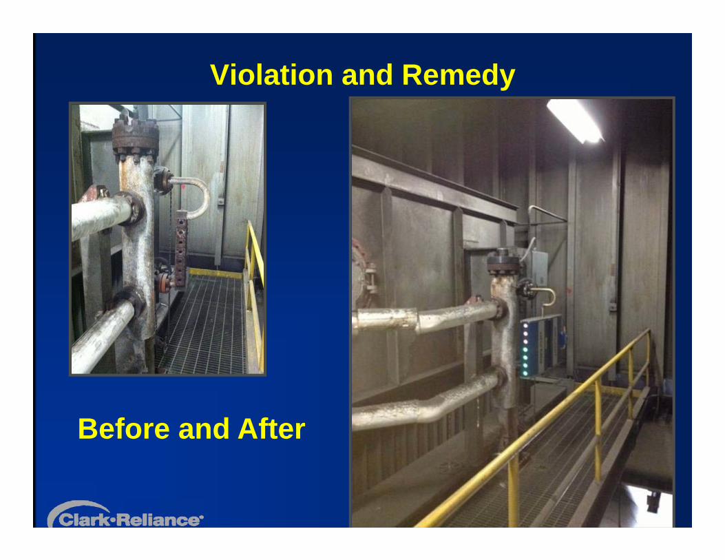
Violation and Remedy
Before and After
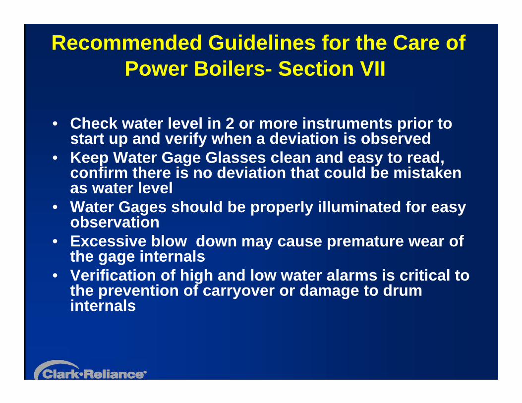
Recommended Guidelines for the Care of Power Boilers- Section VII
• Check water level in 2 or more instruments prior to start up and verify when a deviation is observed
• Keep Water Gage Glasses clean and easy to read, confirm there is no deviation that could be mistaken as water level
• Water Gages should be properly illuminated for easy observation
• Excessive blow down may cause premature wear of the gage internals
• Verification of high and low water alarms is critical to the prevention of carryover or damage to drum internals
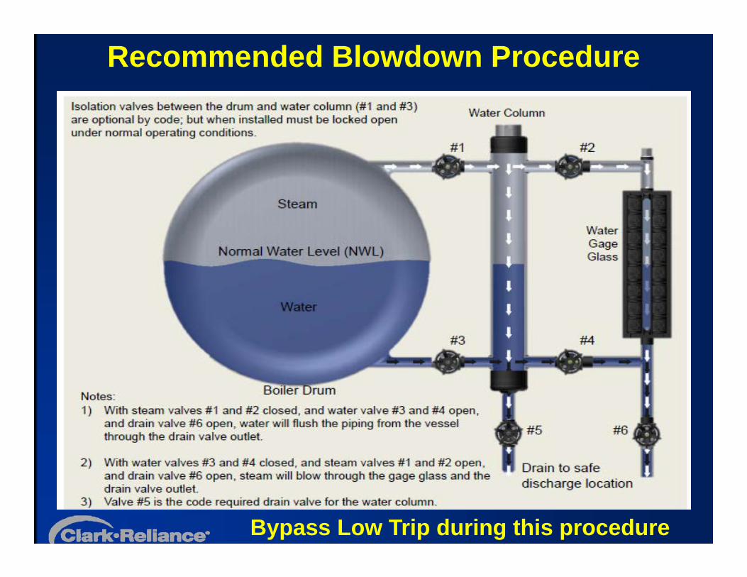
Recommended Blowdown Procedure
Bypass Low Trip during this procedure
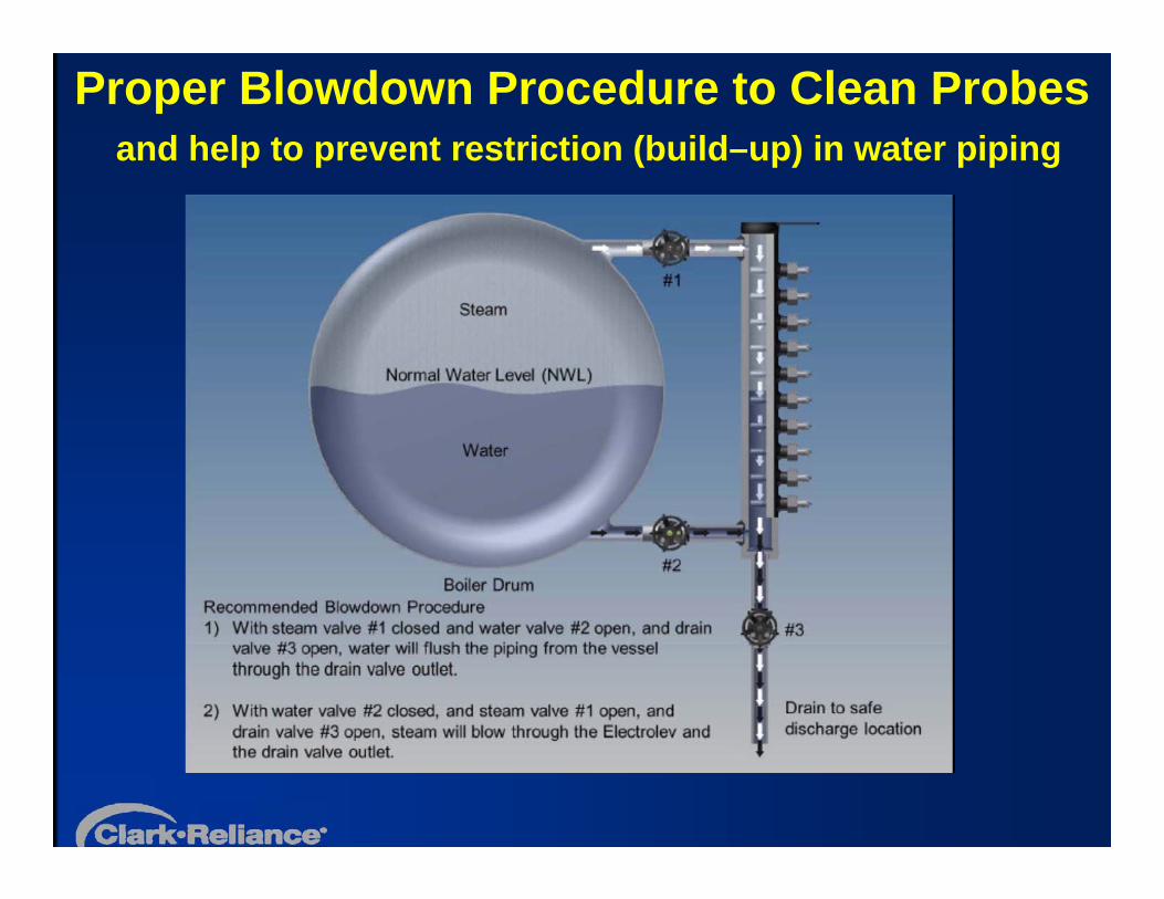
Proper Blowdown Procedure to Clean Probes and help to prevent restriction (build–up) in water piping
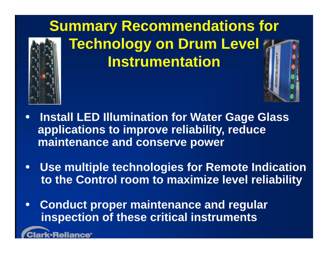
Install LED Illumination for Water Gage Glass applications to improve reliability, reduce maintenance and conserve power
Use multiple technologies for Remote Indication to the Control room to maximize level reliability
Conduct proper maintenance and regular inspection of these critical instruments
Summary Recommendations for Technology on Drum Level
Instrumentation
Specify Code Compliant Instruments
Examine Piping and isolation Valves for leaks, missing insulation, and sediment traps
Consult with the Insurance Underwriter or Plant Safety Department for any specific plant requirements, which may exceed Code minimum
Always follow OEM maintenance instructions for the most accurate and reliable information
Summary Recommendations for Drum Level Instrumentation Installations
Top Questions for Users• Are you having any operational issues with
Water Gage Glasses on Boiler Drum applications?
• What instruments are installed for the display Drum Level Indication in the Control Room?
• Are the water level limit controls on your boiler applications working properly and tested regularly?
• Does the existing Drum Level Instrumentation meet the Code for the Design Pressure (MAWP) of your Boiler Drum?
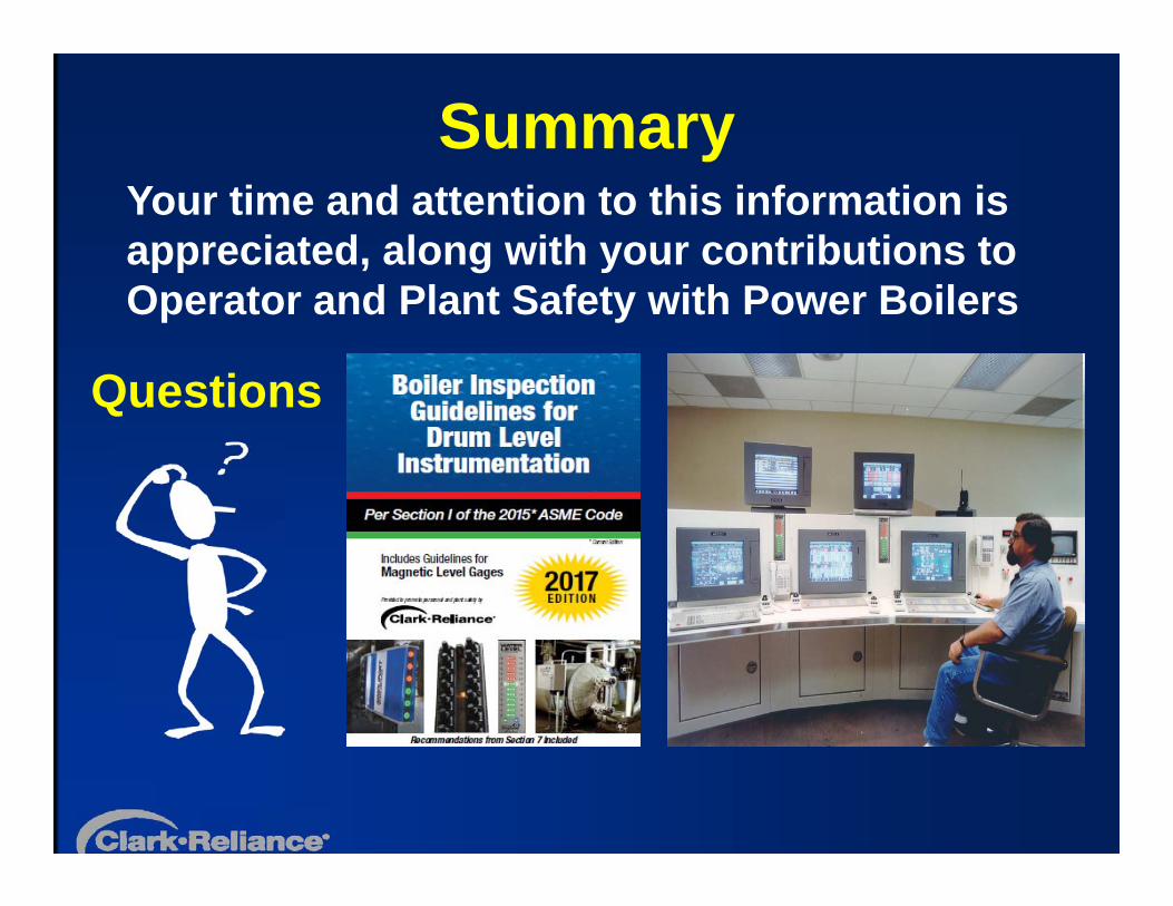
SummaryYour time and attention to this information is appreciated, along with your contributions to Operator and Plant Safety with Power Boilers
Questions

www.Lesman.com/train/
Get Social with Lesman
blog.lesman.com
www.linkedin.com/company/lesman-instrument-company
@Lesman_Inst
www.youtube.com/user/LesmanInstrumentCo