texture development and dynamic recrystallization in ... · texture development and dynamic...
TRANSCRIPT

<Title of Publication> <Edited by> TMS (The Minerals, Metals & Materials Society, <Year>
Texture Development and Dynamic Recrystallization in AA5083 During
Superplastic Forming at Various Strain Rates
Sumit Agarwal1, Paul E. Krajewski2, Clyde L. Briant1
1Brown University, Division of Engineering, Box D, Providence, RI 02912
2General Motors R& D Center, 30500 Mound Road, Warren, MI 48090-9056.
Abstract
Texture development in AA5083 during superplastic forming has been studied at strain rates varying from 0.0005/s to 0.3/s. As shown previously in the literature, a random texture is maintained at slower strain rates (grain boundary sliding), while at the higher strain rates, a fiber texture develops (dislocation creep). At the higher strain rates (>0.03/s), dynamic recrystallization is observed in the necked region of the sample prior to failure. This results in a dramatic transition from very fine grains (~10 µm) to large grains (>100 µm) at a critical strain. At strains above this critical level the grain size gradually decreases with increasing strain. The effect of temperature, strain rate, and constituent particle distribution on the extent and character of the recrystallized region is described. The results are explained in terms of critical strain recrystallization phenomena.
Introduction
AA5083 has been used to produce a variety of superplastically formed (SPF) parts for
the automotive industry [1-3]. The elevated temperature mechanical behavior of AA5083 has been studied extensively [4-13], in order to identify the best conditions for forming these components. In addition to characterization of mechanical behavior, microstructural evolution during superplastic forming has been studied in detail. Texture evolution in AA5083 during SPF has been described [14,15] showing a change from a random texture to a strong deformation texture as strain rate is increased. Dynamic grain growth during SPF in AA5083 has also been characterized, showing a strong link between the rate of grain growth and the amount of grain boundary sliding [16]. Finally, dynamic recrystallization in AA5083-like alloys has been studied either through hot torsion at high strains and strain rates [17] or through the addition of Scandium [18,19]. Much of the research described above has been performed under classic SPF conditions of low strain rates (<0.001/s) and high temperatures (>500ºC). At lower temperatures (450ºC) and higher strain rates (>0.001/s) where AA5083 can often fail by necking, there is little understanding of microstructural evolution, especially in the necked region. The goal of the present paper is to understand microstructural evolution of AA5083 during SPF at lower temperatures than the previous work, with emphasis on texture development and dynamic recrystallization during necking.

Experimental Material - Pechiney Rolled Products, Ravenswood, WV, provided the 1.4 mm thick, AA5083-H18 alloy evaluated in the present study. The composition of this alloy is provided in Table 1.
Table 1. Composition of the AA5083 alloy (w/o).
Mg Mn Cu Si Fe Zn Al AA5083 4.7 0.86 0.04 0.09 0.21 0.05 Bal.
Tensile Testing - Elevated temperature tensile testing was performed using a model 5568 screw-driven Instron, with an Instron 3119-007 furnace and a Merlin data acquisition system. Tensile specimens had a 6.4-mm-wide x 25.4-mm-long gage section and were machined with the rolling direction parallel to the gage length. The samples were heated at the testing temperature for 15 minutes prior to testing, and were water quenched immediately after the test. Constant-strain-rate tests at 450 ºC were performed at strain rates of 0.0005, 0.001, 0.003, 0.01, 0.03, 0.1, and 0.3/s. Constant strain rate tests at 425ºC, 475ºC, and 500ºC were performed at 0.1/s. Microstructural Examination - Samples for electron backscatter diffraction (EBSD) studies were taken from the grip and gauge section of tensile specimens pulled to failure. These samples were primarily examined in the region near the failure surface. For EBSD, the sample was mounted so that the width of the gauge section was exposed. The samples were first mechanically polished and then polished using one of the two methods: (1) Electropolishing for five minutes with 250 ml ethanol, 50 ml perchloric acid solution at 0oC, 15 V DC and a graphite cathode or (2) Etching with 1% Hydrofluoric acid solution for 1 minute 30 seconds at room temperature Both solutions worked well for this material. The samples were then coated with a thin layer of carbon prior to examination by EBSD to ensure good electrical conductivity. EBSD maps were taken along the length of the gauge section starting from the failure end. The individual maps were then stitched using software to create a complete image of the sample. From these maps, subset areas were selected to obtain the texture intensity values in any particular region. For all of the EBSD research we used hardware and software developed by HKL, Inc. This instrumentation was mounted on a JEOL 845 scanning electron microscope. A 60o tilt was used during data collection.
The samples used for EBSD were also examined optically. For optical imaging, the samples were mounted so they were viewed across the thickness. After mechanical polishing, the samples were electrochemically etched for 2 minutes using a 2% fluoroboric acid solution at room temperature, using 25V DC and a stainless steel cathode (Barker’s etch). Etching created an oxide layer on the surface of the specimens, which, when viewed under polarized light, clearly revealed the grains as different colors across the polished surface. The grain size was measured using the linear intercept method. A large number of closely spaced lines were drawn on the micrograph that spanned the entire thickness cross section. These lines were used for both the grain size and the thickness strain measurements.
One important parameter used in this study was the length of the recrystallized region in samples which exhibited necking. The length of the recrystallized region was defined as the length from the fracture end to the farthest point away from the fracture where the entire thickness contain recrystallized grains.

Results
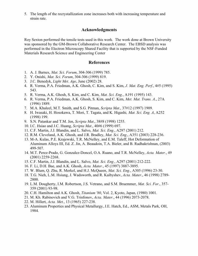
The stress-strain curves for AA5083 at 450ºC for different strain rates are plotted in Figure 1. As strain rate is increased, the behavior changes from classic hardening to one with a high initial yield point and large transient. This transition has been shown to be the result of the transition from grain boundary sliding to dislocation creep as the operative deformation mechanism [13]. One characteristic of the high strain rate samples was that they failed by macroscopic necking rather than cavity interlinkage as shown by the inset pictures in Figure 1.
The failed specimens from the tensile bars used to generate the curves in Figure 1 were examined for texture using EBSD. Perez-Prado et al. [14] have shown that the transition from GBS to dislocation creep can be observed by a change in texture from essentially random to a strong fiber texture as strain rate is increased. Very similar results were observed in the present study. Figure 2 shows an EBSD map obtained from the grip section of a tensile specimen as well as maps from the gage section of samples tested at a variety of strain rates. The grip section (shown in (a)) exhibits a relatively random texture. Similarly oriented grains exhibit the same shade, thus the absence of a dominant color indicates a random structure. A relatively random texture was observed in the sample tested under grain boundary sliding conditions (b); however, the samples tested under dislocation creep conditions exhibited a deformation texture (c&d). This deformation texture was stronger at the higher strain rates.
This evolution of texture with strain rate was further characterized by using texture intensities, which are a quantitative measure of texture in the specimen, obtained from the inverse pole figures. Figure 3 shows a plot of texture intensity as a function of strain rate. Texture intensities from the grip section and a pure aluminum single crystal are also compared for reference. Texture begins to develop at strain rate of 0.003/s and gets stronger for higher strain rates. Texture intensities for 0.1/s and 0.3/s are the highest and nearly the same. Relative to the grip section, no texture is seen for strain rates less than 0.003/s.
The microstructure in the necked region of these samples was examined in detail and is the subject of the remainder of the paper. For necked samples that were tested at the higher strain rates (>0.01/s), a significant change in grain size is observed as the amount of necking increases toward ultimate fracture. The difference in grain structure between samples tested at different strain rates is shown in Figure 4. At the slower strain rate, where GBS controls deformation, the grain size remains relatively fine right up to fracture. However, in the necked sample tested in the dislocation creep regime, very large grains were observed. This change in grain size is abrupt and appears to be the result of dynamic recrystallization occurring at some critical strain. Figure 5 shows an EBSD map of the transition region between fine, textured grains and the large, recrystallized grains in the necked region. The grain size changes abruptly from fine grains (<10µm) to very large grains (>100µm). As the degree of necking increases towards ultimate fracture, the size of the grains in the necked region decreases as shown in Figure 6. Grain size is reduced by over an order of magnitude over the span of less than 2 mm. One interesting thing to note is that the large grains in the necked region of the tensile bar appear independent of the cavities present in the region, that is, their size does not seem to be controlled by the size and distribution of the cavities.
The large grain, recrystallized region was characterized in detail by measuring the grain size as a function of strain using optical micrographs similar to those in Figure 4. Figure 7 shows the grain size plotted as a function of thickness strain for different strain rates at 450oC. In general, the grain size obtained for a given strain is similar for all three strain rates. However, the critical strain for recrystallization, defined as the minimum thickness strain at which recrystallization was observed, decreased with increasing strain rate, thereby increasing the length of the recrystallized region. This latter point can be observed in the data plotted in Figure 8, which shows that the length of the recrystallized region increases with increasing strain rate.

The maximum grain size, which was obtained at the boundary between the recrystallized and unrecrystallized material, increased with increasing strain rate as shown in Figure 9. This effect on grain size was significant with almost a factor of two increase in grain size with the tenfold increase in strain rate.
Finally, the effect of temperature on the recrystallization behavior during necking was studied at a strain rate of 0.1/s. Figure 10 shows the length of the recrystallized zone plotted as a function of test temperature. The length of the zone increases with increasing test temperature between 425oC and 450oC but beyond 450oC the length of the region is quite constant. The sizes of the grains at the onset of the recrystallized region exhibit different behavior with temperature, as shown in Figure 11. Samples tested at temperatures between 425oC and 475oC had a similar grain size; however, the sample tested at 500oC exhibited significantly larger grains.
Discussion
This discussion considers in more detail some of the results presented above. In
particular, these include the evolution of texture and the fact that above a critical strain we observed recrystallization in the specimen.
As shown in Figure 1, the shape of the tensile curve changes with increasing strain rates. At low strain rates, in the grain boundary sliding regime, there is a gradual increase in stress with strain. This “hardening” has been attributed to dynamic grain growth during the tensile test [20]. At strain rates of 0.01/s or greater, a peak stress is observed, followed by a decrease in stress with continued straining. In addition, one can observe from the macrographs in Figure 1 that necks form in samples tested at higher strain rates. The initial yield point and the presence of necking are indicative of the transition in the deformation mechanism from grain boundary sliding to dislocation creep [13].
As the deformation mechanism changes, there are also changes in the microstructure. The results presented in Figures 2 and 3 show that at slow strain rates, where grain boundary sliding controls deformation, there is little texture in the gauge section after the test, but that for samples tested at strain rates of 0.01/s or higher, texture develops in this region. This change is also consistent with the change in deformation mechanism, since dislocation creep would tend to reorient the grains in a preferred direction, relative to the testing axis, whereas grain boundary sliding would leave the material in a random orientation. This result is consistent with that reported by Perez-Prado et al [13], who also found that the occurrence of texture in test samples coincided with the onset of dislocation creep.
One of the most interesting results was the finding that at strain rates greater than 0.01/s, a much larger grain size is observed in the neck region compared to the rest of the sample. It is proposed that these grains are formed by recrystallization for the following reasons. First, the results in Figure 2 show that temperature alone was not sufficient to cause the increase in grain size, since the grip region was at the same temperature as the gauge section during the test. In addition, the order of magnitude increase in grain size was larger than has been attributed to dynamic grain growth during elevated temperature deformation [21]. Abnormal grain growth is ruled out as a possibility as three criteria must be met simultaneously for it to occur [22]. One of these criteria is that at least one grain is significantly larger than the average grain size. This is not observed in these materials. Another indication that these large grains are formed by recrystallization rather than by grain growth is that the grains prior to the fine / coarse transition are highly textured while the large grains beyond the transition are not. If the continued texturing had led to agglomeration of the small grains into larger grains, it is presumed that they would have a similar texture to the region prior to the abrupt transition. Thus it appears that new grains were nucleated in this process. The final indication that this is a recrystallization mechanism is the fact that the grain size is smallest right at the fracture point, and increases with decreasing strain until some critical strain is reached. At lower strain, no recrystallization

is observed. This behavior is consistent with a critical strain recrystallization phenomenon that has been well described for aluminum. [23].
This last point suggests that the probable mechanism for the recrystallization is one of critical strain annealing. The basic mechanism of this process is the following. Below a critical strain there is not enough strain energy to cause recrystallization. Just above the critical strain, a few areas in the material will have sufficient strain energy to start the recrystallization process. Thus, a few recrystallized grains will form and grow to consume the unrecrystallized areas. With increased strain, more nuclei become available and the recrystallized grain size decreases. This basic mechanism appears to explain the present results where an increase in grain size is observed as one travels from the highly strained fracture surface to the region of the sample that is at the critical strain.
This mechanism also allows one to consider other results that were obtained. Figure 8 shows that the critical necking strain for recrystallization decreased with increasing strain rate. This result could be explained if one considers that as the strain rate increases, there is less time for recovery processes to occur and more strain energy is stored. As a result, at the lower strain rates, it takes more strain (or necking) to accumulate the necessary energy for recrystallization, thus increasing the critical strain for recrystallization. The effect of temperature on this recrystallization phenomenon was shown in Figure 10. Changes in test temperature could have two competing effects on recrystallization. On the one hand, the increased temperature could aid recrystallized boundary migration leading to a larger grain size. On the other, the increased temperature could enhance other recovery processes and make recrystallization more difficult.
The results in Figure 11 show that there was an increase in the length of recrystallization material between 425 oC and 450oC but that at 450 oC, 475 oC and 500oC, the recrystallized region was approximately constant. This result suggests that the change in temperature did not allow other recovery processes to occur and inhibit recrystallization; if that were the case we would expect a decrease in the length of recrystallized material with increasing temperature. However, the results in Figure 11 show that at 500oC, the grain size at the recrystallization boundary is larger than at the lower temperatures. This could be explained by either enhanced recovery processes leading to fewer nuclei and therefore a larger recrystallized grain size or enhanced boundary migration leading to a larger grain size.
Finally, it should be noted that for a complete explanation of this process, one has to consider the fact that this recrystallization is occurring during a tensile test. To have a complete understanding of the process we need to obtain additional information about the incubation time for recrystallization and the speed of grain boundary movement relative to the test time. For example, the mechanism presented here assumes that once the neck region is formed and a few recrystallized grains are beginning to grow, the strain increases rapidly enough to produce additional nuclei before the original ones consume the entire sample, thus leading to the smaller grain size in this region. These issues are currently being investigated.
Conclusions
1. During deformation at 450 ºC, the texture intensity in AA5083 increases with increasing strain rate from a relatively random texture to a strong fiber texture.
2. Dynamic recrystallization occurs after the onset of necking at strain rates greater than 0.01/s. The dynamic recrystallization only occurs in the necked region.
3. Recrystallization occurs at a critical strain that decreases with increasing strain rate.
4. At the critical strain, large (>100 µm) grains are observed. As the strain in the necked region increases, the grain size decreases.
5. The length of the recrystallization zone increases both with increasing temperature and strain rate.
Acknowledgments
Roy Sexton performed the tensile tests used in this work. The work done at Brown University was sponsored by the GM-Brown Collaborative Research Center. The EBSD analysis was performed in the Electron Microscopy Shared Facility that is supported by the NSF-Funded Materials Research Science and Engineering Center
References
1. A. J. Barnes, Mat. Sci. Forum, 304-306 (1999) 785. 2. Y. Onishi, Mat. Sci. Forum, 304-306 (1999) 819. 3. J.C. Benedyk, Light Met. Age, June (2002) 28. 4. R. Verma, P.A. Friedman, A.K. Ghosh, C. Kim, and S. Kim, J. Mat. Eng. Perf., 4#5 (1995)
543. 5. R. Verma, A.K. Ghosh, S. Kim, and C. Kim, Mat. Sci. Eng., A191 (1995) 143. 6. R. Verma, P.A. Friedman, A.K. Ghosh, S. Kim, and C. Kim, Met. Mat. Trans. A., 27A
(1996) 1889. 7. M.A. Khaleel, M.T. Smith, and S.G. Pitman, Scripta Mat., 37#12 (1997) 1909. 8. H. Iwasaki, H. Hosokawa, T. Mori, T. Tagata, and K. Higashi, Mat. Sci. Eng. A, A252
(1998) 199. 9. S.N. Patankar and T.M. Jen, Scripta Mat., 38#8 (1998) 1255. 10. I.C. Hsiao and J.C. Huang, Scripta Mat., 40#6 (1999) 697. 11. C.F. Martin, J.J. Blandin, and L. Salvo, Mat. Sci. Eng., A297 (2001) 212. 12. R.M. Cleveland, A.K. Ghosh, and J.R. Bradley, Mat. Sci. Eng., A351 (2003) 228-236. 13. M-A. Kulas, P.E. Krajewski, T.R. McNelley, and E.M. Taleff, Hot Deformation of
Aluminum Alloys III, Ed. Z. Jin, A. Beaudoin, T.A. Bieler, and B. Radhakrishnan, (2003) 499-507.
14. M.T. Perez-Prado, G. Gonzalez-Doncel, O.A. Ruano, and T.R. McNelley, Acta. Mater., 49 (2001) 2259-2268.
15. C.F. Martin, J.J. Blandin, and L. Salvo, Mat. Sci. Eng., A297 (2001) 212-222. 16. F. Li, D.H. Bae, and A.K. Ghosh, Acta. Mater., 45 (1997) 3887-3895. 17. W. Blum, Q. Zhu, R. Merkel, and H.J. McQueen, Mat. Sci. Eng., A305 (1996) 23-30. 18. T.G. Nieh, L.M. Hsiung, J. Wadsworth, and R. Kaibyshev, Acta. Mater., 46 (1998) 2789-
2800. 19. L.M. Dougherty, I.M. Robertson, J.S. Vetrano, and S.M. Bruemmer, Mat. Sci. For., 357-
359 (2001) 93-98. 20. C.H. Hamilton and A.K. Ghosh, Titanium '80, Vol. 2, Kyoto, Japan, (1980) 1001. 21. M. Kh. Rabinovich and V.G. Trinfonov, Acta. Mater., 44 (1996) 2073-2078. 22. M. Hillert, Acta. Met., 13 (1965) 227-238. 23. Aluminum Properties and Physical Metallurgy, J.E. Hatch, Ed., ASM, Metals Park, OH,
1984.
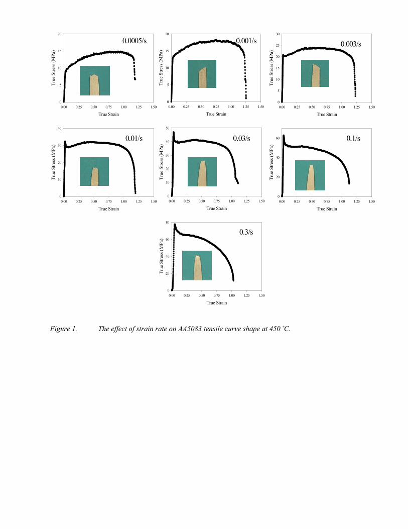
Figure 1. The effect of strain rate on AA5083 tensile curve shape at 450 ˚C.
True Strain0.00 0.25 0.50 0.75 1.00 1.25 1.50
True
Stre
ss (M
Pa)
0
5
10
15
20
True Strain0.00 0.25 0.50 0.75 1.00 1.25 1.50
True
Stre
ss (M
Pa)
0
5
10
15
20
True Strain0.00 0.25 0.50 0.75 1.00 1.25 1.50
True
Stre
ss (M
Pa)
0
5
10
15
20
25
30
True Strain0.00 0.25 0.50 0.75 1.00 1.25 1.50
True
Stre
ss (M
Pa)
0
10
20
30
40
True Strain0.00 0.25 0.50 0.75 1.00 1.25 1.50
True
Stre
ss (M
Pa)
0
10
20
30
40
50
True Strain0.00 0.25 0.50 0.75 1.00 1.25 1.50
True
Stre
ss (M
Pa)
0
20
40
60
True Strain0.00 0.25 0.50 0.75 1.00 1.25 1.50
True
Stre
ss (M
Pa)
0
20
40
60
80
0.0005/s 0.001/s 0.003/s
0.01/s 0.03/s 0.1/s
0.3/s
True Strain0.00 0.25 0.50 0.75 1.00 1.25 1.50
True
Stre
ss (M
Pa)
0
5
10
15
20
True Strain0.00 0.25 0.50 0.75 1.00 1.25 1.50
True
Stre
ss (M
Pa)
0
5
10
15
20
True Strain0.00 0.25 0.50 0.75 1.00 1.25 1.50
True
Stre
ss (M
Pa)
0
5
10
15
20
25
30
True Strain0.00 0.25 0.50 0.75 1.00 1.25 1.50
True
Stre
ss (M
Pa)
0
10
20
30
40
True Strain0.00 0.25 0.50 0.75 1.00 1.25 1.50
True
Stre
ss (M
Pa)
0
10
20
30
40
50
True Strain0.00 0.25 0.50 0.75 1.00 1.25 1.50
True
Stre
ss (M
Pa)
0
20
40
60
True Strain0.00 0.25 0.50 0.75 1.00 1.25 1.50
True
Stre
ss (M
Pa)
0
20
40
60
80
0.0005/s 0.001/s 0.003/s
0.01/s 0.03/s 0.1/s
0.3/s
Figure2. OIM images of AA5083 samples tested at 450oC were taken from the following areas: (a) in the grip region of a sample tested at 0.3/s, (b) from the gage section of a sample tested at 0.0005/s, (c) in the gage section of a sample tested at a strain rate of
0.01/s, and (d) in the gage section of a sample tested at a strain rate of 0.3/s.
a
c
b
d

Figure 3: Variation of texture intensity with strain rate in AA5083 tested at 450oC.
Figure 4: Optical image showing the grain structure near the fracture surface for AA5083 samples tested at 450oC at a strain rate of (a) 0.0005/s and (b) 0.1/s.
05
1015202530354045
0.0001 0.001 0.01 0.1 1
Strain rate (S-1)
Text
ure
Inte
nsity
Guage regionGrip regionSingle crystal
a b
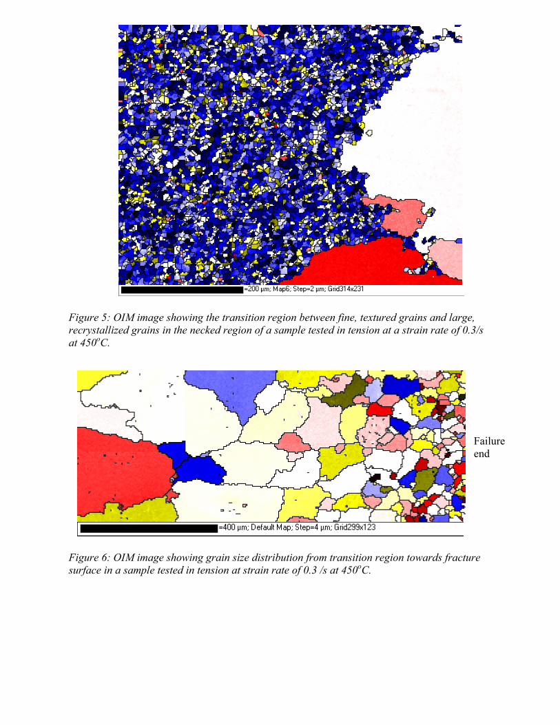
Figure 5: OIM image showing the transition region between fine, textured grains and large, recrystallized grains in the necked region of a sample tested in tension at a strain rate of 0.3/s at 450oC. Figure 6: OIM image showing grain size distribution from transition region towards fracture surface in a sample tested in tension at strain rate of 0.3 /s at 450oC.
Failure end

Figure 7: The effect of thickness strain in the necked region of tensile bars tested at 450oC on recrystallized grain size.
Figure 8: Effect of strain rate on length of recrystallized region in the necked region of tensile samples of AA5083 tested at 450oC.
0
20
40
60
80
100
120
140
160
0.65 0.7 0.75 0.8 0.85 0.9Thickness strain
Av.
gra
in s
ize
(mic
rons
)
0.3/Sec0.1/Sec0.03/Sec
0
0.5
1
1.5
2
2.5
3
0 0.1 0.2 0.3 0.4Strain rate (S-1)
Leng
th (m
m)

Figure 9: Effect of strain rate on grain size at the onset of recrystallization in the necked region of tensile samples of AA5083 tested at 450oC.
Figure 10: Effect of temperature on the size of the recrystallization region in necked tensile samples of AA5083 tested at 450oC.
020406080
100120140160
0.01 0.1 1
Strain rate (S-1)
Max
. gra
in s
ize
(mic
rons
)
0
0.2
0.4
0.6
0.8
1
1.2
420 440 460 480 500 520
Temperature (oC)
Leng
th (m
m)
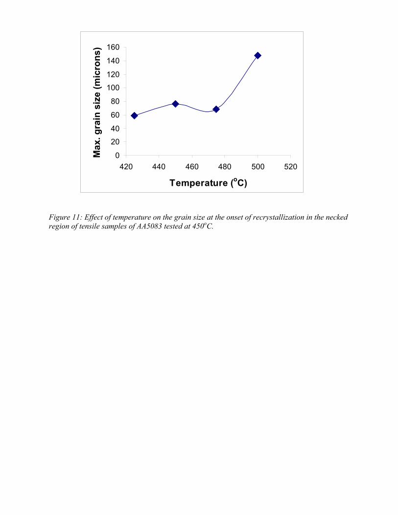
Figure 11: Effect of temperature on the grain size at the onset of recrystallization in the necked region of tensile samples of AA5083 tested at 450oC.
0
20
40
60
80
100
120
140
160
420 440 460 480 500 520
Temperature (oC)
Max
. gra
in s
ize
(mic
rons
)