testing of plastics and rubber - cdn.pressebox.de · bakelite, found in early telephones and of...
TRANSCRIPT

Testing of plastics and rubber
Intelligent Testing
FP 2
69 2
.040
8
Testing systems

2
Picture sources, front page: BASF AG, Bayer AG, Continental AG, Solvay SA, Recaro GmbH & Co.KG, BIG-Spielwarenfabrik
List of contents
The Zwick-Roell Group ....................................................................................................................................... 3Plastics and rubbers: Development, structure and properties .............................................................................. 4Application examples, typical test curves ............................................................................................................ 6Sample preparation .......................................................................................................................................... 10Specimen shapes, dimensions und cutting dies ................................................................................................ 12Dimension measurement .................................................................................................................................. 16Material testing machines ................................................................................................................................. 18• Typical fields of application ............................................................................................................................. 18• Measurement and control systems ................................................................................................................ 19• Load frames .................................................................................................................................................. 20• Drive systems ................................................................................................................................................ 22• testXpert® II Software for materials testing ...................................................................................................... 24• Load cells ...................................................................................................................................................... 28• Specimen holders.......................................................................................................................................... 29• Extensometers .............................................................................................................................................. 35• Automatic specimen feeding by Handling Systems ........................................................................................ 40• Temperature chambers .................................................................................................................................. 42Servohydraulic testing machines ....................................................................................................................... 45High speed testing machines ............................................................................................................................ 46Falling weight testers ........................................................................................................................................ 47Pendulum impact testers .................................................................................................................................. 48Extrusion plastomers ........................................................................................................................................ 52HDT and Vicat VST testers ............................................................................................................................... 54Rebound resilience testers ................................................................................................................................ 56Abrasion testers ............................................................................................................................................... 57Ball-type rebound resilience testers ................................................................................................................... 57Hardness testers and machines ........................................................................................................................ 58Zwick Sevices .................................................................................................................................................. 61Overview of standards and test equipment ....................................................................................................... 64Contact ............................................................................................................................................................ 68
This catalogue provides an overviewof testing instruments, machines,and systems of the Zwick Roell AGfor use in the plastics and rubberindustry and in the correspondingresearch and test institutes andtraining centers.
This is only a part of the extensiveoverall program of the Zwick RoellAG.

3
Since 1992, these companies haveformed the Zwick Roell group, andin July 2001, the company groupwas converted into a stock corpo-ration: the Zwick Roell AG. Part ofthis stock corporation are thecompanies Zwick, Toni Technik,Indentec Ltd., and since may 2002Acmel Labo. These companiessupply an extensive program formaterials, component, and functionaltests – from the manually operatedhardness tester up to complexrobotic test systems for the twenty-four-seven production control.
By acquisition of the Germancompany GTM (2007) and theAustrian company Messphysik(2006) the know-how of the ZwickRoell AG in the field of force andelongation measurement has beensafed and enriched.
Zwick has many years of experi-ence, combined with a multitude ofsupplied systems, and this experi-
The headquarter of the Zwick Roell AG and the Zwick GmbH & Co. KG at Ulm, Germany
The Zwick Roell AG –more than a centuryof experience inmaterials testing
Mechanical-technological testing isone of the oldest disciplines ofmaterials testing. As early as in the15th and 16th century, Leonardo daVinci and Galileo Galilei were alreadyconsidering the flexural stressingand elastic behaviour of materials.In the course of time furtherknowledge was obtained. In themiddle of the 18th century the firsttesting machines finally appearedin France.
Since 1920 the company Roell &Korthaus was involved in thematerials testing business. In 1937Zwick built its first testing machinesand systems for mechanical testingof materials, and many years prior tothat in 1876, a Professor Seger hadfounded a chemical laboratory aspart of a scientific technologicalconsulting company for non-metallicmaterials. During the 20th centurythe present company, Toni Technik,has evolved from these origins andis now considered a leading expertin test systems for building materials.MFL (Mohr & Federhaff) – a companythat was founded in 1870 – becamepart of the Zwick Roell group andinterestingly, Carl Benz (of MercedesBenz fame) was one of theiremployees.
ence is continuously supplementedby constant communication withcustomers. On this solid base thecompany supplies a wide range ofhigh-performance products – fromthe economical standard qualitycontrol machine up to customisedsolutions designs for specific testrequirements. Modern mechanics,high-performance electronics andthe application-oriented softwareare the prerequisite for the versatilityand the high “intelligence” of thesemodern testing machines andsystems.
The services of the Zwick Roell AGgo far beyond the supply of products.In 1994 the company received itscertification ISO 9001 accreditedhelping to guarantee a consistentlyhigh product and service quality.With its accredited calibrationlaboratories, the companies of theZwick Roell AG are able to verifyand calibrate test systems and toissue internationally recognizedcertificates.

4
Plastics and rubbers-development, structureand properties
Plastics
In 1861, the first polymeric plasticwas patented for Alexander Parkesunder the name Parkesine. It was akind of celluloid then patented byHyatt in 1870, and in 1908, Bakelandand Lebach made the chemistry ofphenolic resins more transparent.Bakeland then discovered Bakelite,the first plastic to be broadly used,whilst Hermann Staudinger de-scribed the structure of polymericmaterials as macromolecules andthus discovered the basis of macro-molecular chemistry. Ziegler andNatta worked on the polymerizationof ethylene. On this basis,Montedison produced polypro-pylene in 1957 for the first time.
Today, the most important rawmaterial is petroleum which – decom-posed in its elements – supplies thebasic material of plastics. Thesemolecules are linked to large chains:the polymers. When talking aboutplastics one can imagine a mass ofmolecule chains. Depending on howthese chains are linked to each other,different groups of plastic will result:
Thermoplastics
The molecule chains are linear andbranched. Very often a large portionof spaghetti is taken as example.At ambient temperature, thermo-plastics are often hard or even brittle.When heated, the material softensor is given plasticity because themolecule chains slide past eachother more easily. Thermoplasticsare the largest group of plastics. Thefour most important thermoplasticsare PE, PP, PVC and PS.
Thermosetting plastics(thermohardening plastics)
The molecule chains of thermo-setting plastics are linked moreclosely. The cross-links are thermallynot soluble, so thermosetting plasticsdo not melt. The classicalthermosetting plastic material isBakelite, found in early telephonesand of many other commodities.Modern materials are unsaturatedpolyester, linked polyurethanes andepoxy resins.
Elastomers
Elastomers are polymers which arebuilt up of macromolecules andwhich are three-dimensionallycross-linked. The elastic rubberlikeproperties of these materials are theresult of the cross-link of single
polymer chains (vulcanization).In modern usage, elastomers aretherefore also called rubber.
Testing of plastics
CAMPUS® (Computer AidedMaterial Preselection by UniformStandards) supplies tested valuesfor mechanical, thermal, electricaland process-specific properties ofalmost every type of plastics. Thelist of rheological, mechanical,thermal, electrical and other pro-perties to be tested are standar-dized in ISO 10350 (single pointdata). Many material propertiesrequired as construction data arestandardized in ISO 11403(multipoint data). ISO 17282provides details for design data.
See: www.campusplastics.com
Thermoplastic Elastomers Thermosettingmaterials materials
Structure of the molecule chains
Simple chains or Wide-range cross-linked Closely cross-linkedshrub-type ramifications in all directions
Properties
• Quite soft • Molecular structure • Hard and brittle• Deformable under similiar to a • Temperature-resistant
temperature fishing net • Non-deformable• Deformation process • swellable • Non-meltable
is repeatable • rubber-like elasticity
Types of plastics
Polyethylene (PE) Rubber Epoxy resinsPolystyrene (PS) Silicone Polyester resinsPolyamide (PA) Polyurethane Phenolic resinsPolyester Polyurethane
Structure of plastics
5
Short Designation Applicationsign examplesNR Natural Rubber Medical gloves, latex,
blending component forsynthetic rubber
SBR Styrene Butadiene Rubber All-purpose rubber,(originally “Buna – S”) tire industry
CR Polychloropren Rubber Contact adhesives, conveyor belts,sealings, hoses
IIR Isobutene-Isoprene Sealings, membranes,(Butyl) Rubber cable insulations
EPDM Ethylene-Propylene- Roof and pond foils,Diene Monomer sealings in automotive industry
NBR Nitrile Butadiene Oil and fuel resistant sealings,Rubber membranes, hoses
SI/MQ/ Silicone Rubber Sealings for freezers, stoves,PMQ/ window and cabin sealingsVMQ of airplanes.FPM Fluorocarbon Rubber Sealings, moulded parts,
hoses with a high temperatureand chemical resistance, belts
PUR Polyurethane Foams
Rubbers
When the Spanish conquerorscame to Mexico and South Americain the beginning of the 16th century,they saw Indians playing with astrange bouncing ball. The Indianscalled the material of the ball « Cahu chu » (crying tree). Today we callthis Latex-tree Hervea brasiliensis.
More than 200 years later, rubberwas used in Europe as well. In1770, the English minister Priestleywas credited with the discovery ofthe use of rubber as an eraser.
Finally, in the 19th century, peoplediscovered the precious propertiesof rubber: its waterproofing andelasticity. Rubber mixed withturpentine oil was used tomanufacture bags, hot-water bagsand life buoys. In 1824 the firstbraces and suspenders weremanufactured. The rain coats thatwere available at that time werehard as stone in winter and stickyin the summer.
In 1844, Charles Goodyear pat-ented his revolutionary discovery. Formany years he had been experi-menting with rubber, and one day,some rubber mixed with sulfurdropped onto a hot stove. Duringcarbonization, the grey, raw rubberturned into a smooth and solidmaterial with good properties.Goodyear had discovered thevulcanization process.At that time, the demand for rubberwas exclusively covered by suppliesfrom the Brazilian rain forest. Brazilheld the monopoly and suspiciouslywatched that no seeds of the treewere taken to other countries. In 1876,the English adventurer Sir Wickhamsmuggled rubber seeds to London,and the resultant seedlings weresent to India where they could be
planted on English plantations. In1880, Asian rubber was sold on theworld market for the first time.Today, the world economy gets 3.5million tons a year from the planta-tions all over the world.
Synthetic rubber
As early as 1826 Michael Faradaydiscovered the chemical structureof rubber, and in 1909, the Germanchemist Fritz Hofmann was thefirst to patent the productionprocess of synthetic rubber. AfterWorld War I, the patent wasexpropriated and the productionwas discontinued.In 1930, America began large-scalemanufacture of synthetic rubber and –since they had lost their plantationsdue to Japan’s entry into war – theybuilt up huge production capacitiesof 840,000 t by 1945.
The rubber industry strongly dependson the availability of petroleum, andas a result about 70 % of the worldrequirements are manufacturedsynthetically.
There are about 20 different types ofsynthetic rubber, many of them withspecial properties. Just as naturalrubber, they consist of longmolecule chains creating a convo-luted network. For vulcanization, thechains are provided with cross-links.Classical example is the sulfurvulcanization of natural rubber. Thenumber of cross-links determinesthe properties of rubber: soft rubberwith a few links, hard rubber withmany links.
Overview of rubber

6
Application test-curve in testXpert® II Example of mounting
Thermoplastic andthermosetting materials
Standard: ISO 527-2Type: tensileMaterial: semi-rigid plasticGrips: wedge-screwExtensometer: multiXtensTest speed: 1 mm/min, 50 mm/min
Standard: ISO 527-2Type: tensileMaterial: rigid plasticGrips: wedgeExtensometer: MacroTest speed: 1 mm/min, 50 mm/min
Standard: ISO 178Type: flexural (3-point)Material: rigid plasticGrips: flexural toolExtensometer: crosshead monitorTest speed: 2 mm/min, 50 mm/min
Rubbers and elastomers
Standard: ISO 37Type: tensileMaterial: PIB dumbbellGrips: pincerExtensometer: mechanical long travelTest speed: 500 mm/min

7
Application test-curve in testXpert® II Example of mounting
Rubbers and elastomers
Standard: ISO 34-1Type: tear testMaterial: SBRSpecimen: angleGrips: pneumaticExtensometer: crosshead monitorTest speed: 500 mm/min
Standard: ISO 34-1Type: tear testMaterial: SBRSpecimen: trouserGrips: pneumaticExtensometer: crosshead monitorTest speed: 500 mm/min
Fibre reinforced composites
Standard: ISO 527-4Type: tensileMaterial: CRPSpecimen: type 3Grips: hydraulicExtensometer: MacroTest speed: 2 mm/min
Standard: ISO 14130Type: interlaminar shearMaterial: CRPGrips: flexural deviceExtensometer: crosshead monitorTest speed: 1 mm/min

8
Application test-curve in testXpert® II Example of mounting
Flexiblecellular plastics
Standard: ISO 1798Type: tensileMaterial: PURGrips: pneumaticExtensometer: mechanical long travelTest speed: 500 mm/min
Standard: ASTM D 3574 - B1Type: indentation hardnessMaterial: PURGrips: indentorExtensometer: crosshead monitorTest speed: 48 mm/min
Standard: ISO 3386Type: compression propertiesMaterial: PURGrips: compression platesExtensometer: crosshead monitorTest speed: 50 mm/min
Standard: ISO 8067Type: tear testMaterial: PURSpecimen: trouserGrips: pincerExtensometer: crosshead monitorTest speed: 50 mm/min

9
Application test-curve in testXpert® II Example of mounting
Thin sheetingand plastic film
Standard: ISO 527-3Type: tensileMaterial: PVC filmSpecimen: strip, 10mm largeGrips: screwExtensometer: crosshead monitorTest speed: 100 mm/min
Standard: EN 14477Type: puncture testMaterial: PE filmGrips: test deviceExtensometer: crosshead monitorTest speed: 100 mm/min
Adhesives and sealings
Standard: ISO 4578Type: 90° peel testMaterial: tapeGrips: test deviceExtensometer: crosshead monitorTest speed: 100 mm/min
Standard: customer specificType: opening of sealingMaterial: food packagesGrips: special deviceExtensometer: crosshead monitorTest speed: 100 mm/min

10
Sample Preparation
Injection molding andcompression moldingTo characterize thermoplastic andthermosetting materials, specimensare made by injection or direct com-pression molding. The applied pro-cessing parameters such as pressure,temperature and shear-rate stronglyinfluence the materials behavior.Thermosetting materials:• Compression molding (ISO 295)• Injection molding (ISO 10724-1)Thermoplastic materials:• Compression molding (ISO 293)• Injection molding (ISO 294, part 1-4)
Multipurpose specimen,ISO 3167The local shear-rate during processingis influenced by the shape of thespecimen. This means that the resultsof specimens with different shapesare not normally comparable.For this reason a multipurpose specimenhas been defined in ISO 3167, which isto be used for a variety of different testssuch as tensile, compression, flexure,creep, hardness and impact.
MachiningFor testing semi-finished and finishedparts it is generally required to knowthe materials characteristics afterhaving achieved its final shape.The specimens are then machinedin accordance to ISO 2818 or othermaterial-specific standards.Specimens made of softer materials(e.g. hardness of less than 85 ShoreA), especially rubber, elastomers, softplastics, and specimens made ofthin sheet and film are manufacturedrelatively easily with cutting pressesand special cutting tools. Higherhardness values reduce the life ofthe cutting dies.In particular, the thicker and harderthe specimen is, the more difficult itis to cut. These materials have to bemachined by milling, sawing, planingor blanking.
Zwick notch cutter ZNOThe Zwick ZNO notch milling machineis used to notch plastic specimens inaccordance with standards ASTM D256, ASTM D 6110, ISO 179, ISO 180and ISO 8256 (Charpy and Izod tests).
Advantages and features• Steplessly adjustable cutting
speed and feed rate• Manual setting of residual width by
means of fine screw adjustment• Acrylic safety hood• Use of interchangeable specimen
magazines• Quick-clamping device for
magazines
• Single-tooth polycrystallinediamond milling cutter for optimalnotching results
• Connection for external compressedair or nitrogen for specimen cooling
• Option: Digital measuring stationfor residual width.
Standard Spezimen size (LxBxH)
ISO179-1 80 x 10 x 4ISO180 80 x 10 x 4ISO8256-1 80 x 10 x 6ASTM D 256 2.5 x 0.5 x 0.125...0.5ASTM D 6110 5.0 x 0.5 x 0.125...0.5ISO179-1(historic)50 x 6 x 4DIN53435 15 x 10 x 1.2...4.6(Dynstat)
All dimensions in [mm]
Standard Shape A Shape B Shape C
ISO179-1 single or double notch single or double notch single or double notchISO180 single notch single notch -ISO8256-1 double notch - -ASTM D 256 single notch - -ASTM D 6110 single notch - -
Sketch
Radius of 0.25 mm ± 0.05 mm 1.00 mm ± 0.05 mm 0.10 mm ± 0.02 mmnotch root
Single or double notches for impact specimen are easily milled by using the Zwick notch cutter ZNO

11
Strip cutter for plastics film
Parallel strip-type specimen fortensile tests are taken from a sheetmaterial with a straight and notch-free cut.
This strip-cutter allows strips to becut from a sheet of about 180 mmby 300 mm (7” by 12”), fixed on thecutting drum.
Zwick cutting presses andtools
Zwick offers a wide range of cuttingdevices for both standardized andspecial specimen shapes. A list ofthe most common types is shown inthe following tables.
The cutting tool consists of 11blades, allowing all strips to be cutin a single operation.
Specimen dimensionsLength: approx. 230 mmWidth: 10 or 15 mmThickness: 5 to 900 µm
Strip cutter dimensionsL x W x H: 420 x 290 x 240 mmWeight: approx. 29 kg
Advantages of cutting devices:• Quick and easy changing of
cutting dies• Mechanical specimen ejecting sys-
tem (minimising the risk of injuryfrom the sharp cutting edges)
• Possibility to sharpen the cuttingdie several times
• Cutting die and ejecter are twomodular parts so that the cuttingdie is available as a separatespare part.
The Strip cutter allows sampling of up to 10 strip-type specimen in one single cutting move-ment. The cutting edges are perfectly straight, parallel and notch free.
Cutting presses
Reference H04.71011) ZCP020 H02.7108Application circular specim. all shapes all shapesMax. applicable load 5 kN 20 kN 35 kNPush rod stroke 25 mm 41 mm 30 mmMax. distance push rod-table 65 mm 155 mm 70 mmAdjustment of push rod stroke 12 mm 25 mm -Adjustment of table elevation - - 70 mmProjection 46 mm 125 mm 110 mmAnvil table swiveling 250 x 250 mm 350 x 215 mmCompressed air supply - - 6 barNet weight 40 kg 55 kg 75 kg1) Cutting dies can be used for ring-shaped specimen up to a diameter of 80 mm, square-shaped
specimen up to 75 mm and rectangular and dumbbell shaped specimens up to a size of 160 x 30 mmPneumatic cutting press 7108 for allspecimen shapes
Excentric cutting press 7101 with ringcentering device for circular specimens
Knee-lever cutting press ZCP020 for allspecimen shapes
12
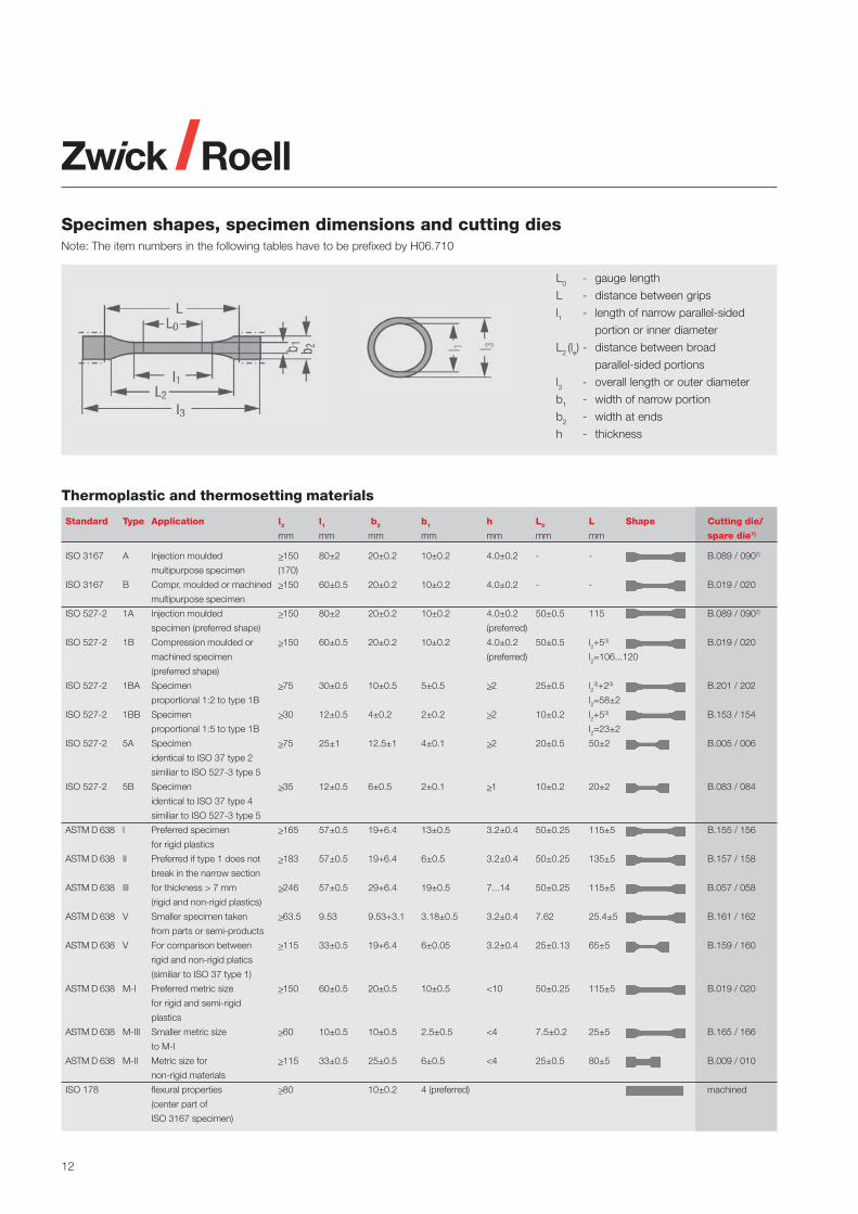
L0 - gauge length
L - distance between grips
l1 - length of narrow parallel-sided
portion or inner diameter
L2 (le) - distance between broad
parallel-sided portions
l3 - overall length or outer diameter
b1 - width of narrow portion
b2 - width at ends
h - thickness
Thermoplastic and thermosetting materials
Standard Type Application l3 l1 b2 b1 h L0 L Shape Cutting die/
mm mm mm mm mm mm mm spare die1)
ISO 3167 A Injection moulded >_150 80±2 20±0.2 10±0.2 4.0±0.2 - - B.089 / 0902)
multipurpose specimen (170)
ISO 3167 B Compr. moulded or machined >_150 60±0.5 20±0.2 10±0.2 4.0±0.2 - - B.019 / 020
multipurpose specimen
ISO 527-2 1A Injection moulded >_150 80±2 20±0.2 10±0.2 4.0±0.2 50±0.5 115 B.089 / 0902)
specimen (preferred shape) (preferred)
ISO 527-2 1B Compression moulded or >_150 60±0.5 20±0.2 10±0.2 4.0±0.2 50±0.5 l2+53) B.019 / 020
machined specimen (preferred) l2=106...120
(preferred shape)
ISO 527-2 1BA Specimen >_75 30±0.5 10±0.5 5±0.5 >_2 25±0.5 l23)+23) B.201 / 202
proportional 1:2 to type 1B l2=58±2
ISO 527-2 1BB Specimen >_30 12±0.5 4±0.2 2±0.2 >_2 10±0.2 l2+53) B.153 / 154
proportional 1:5 to type 1B l2=23±2
ISO 527-2 5A Specimen >_75 25±1 12.5±1 4±0.1 >_2 20±0.5 50±2 B.005 / 006
identical to ISO 37 type 2
similiar to ISO 527-3 type 5
ISO 527-2 5B Specimen >_35 12±0.5 6±0.5 2±0.1 >_1 10±0.2 20±2 B.083 / 084
identical to ISO 37 type 4
similiar to ISO 527-3 type 5
ASTM D 638 I Preferred specimen >_165 57±0.5 19+6.4 13±0.5 3.2±0.4 50±0.25 115±5 B.155 / 156
for rigid plastics
ASTM D 638 II Preferred if type 1 does not >_183 57±0.5 19+6.4 6±0.5 3.2±0.4 50±0.25 135±5 B.157 / 158
break in the narrow section
ASTM D 638 III for thickness > 7 mm >_246 57±0.5 29+6.4 19±0.5 7...14 50±0.25 115±5 B.057 / 058
(rigid and non-rigid plastics)
ASTM D 638 V Smaller specimen taken >_63.5 9.53 9.53+3.1 3.18±0.5 3.2±0.4 7.62 25.4±5 B.161 / 162
from parts or semi-products
ASTM D 638 V For comparison between >_115 33±0.5 19+6.4 6±0.05 3.2±0.4 25±0.13 65±5 B.159 / 160
rigid and non-rigid platics
(similiar to ISO 37 type 1)
ASTM D 638 M-I Preferred metric size >_150 60±0.5 20±0.5 10±0.5 <10 50±0.25 115±5 B.019 / 020
for rigid and semi-rigid
plastics
ASTM D 638 M-III Smaller metric size >_60 10±0.5 10±0.5 2.5±0.5 <4 7.5±0.2 25±5 B.165 / 166
to M-I
ASTM D 638 M-II Metric size for >_115 33±0.5 25±0.5 6±0.5 <4 25±0.5 80±5 B.009 / 010
non-rigid materials
ISO 178 flexural properties >_80 10±0.2 4 (preferred) machined
(center part of
ISO 3167 specimen)
Specimen shapes, specimen dimensions and cutting diesNote: The item numbers in the following tables have to be prefixed by H06.710

13
Standard Type Application l3 l1 b2 b1 h L0 L Shape Cutting die/
inch inch inch inch inch inch inch spare die1)
ASTM D 638 I Preferred specimen >_6.5 2.25 >_0.75 0.5 0.13±0.02 2 4.5 B.167 / 168
for rigid plastics
ASTM D 638 II Preferred if type 1 does not >_7.2 2.25 >_0.75 0.25 0.13±0.02 2 5.3 B.061 / 062
break in the narrow section
ASTM D 638 III For specimen thickness >_9.7 2.25 >_1.13 0.75 0.28/0.55 2 4.5 B.057 / 058
>7 mm (rigid and non-rigid
plastics)
ASTM D 638 V Smaller specimen taken from >_2.5 0.375 >_0.375 0.125 0.32±0.02 0.3 1 B.161 / 162
parts or semi-products
ASTM D 638 IV For comparison between >_4.5 1.3 >_0.75 0.25 0.32±0.02 1 2.5 B.163 / 164
rigid and non-rigid plastics
(similiar to ISO 37, type 1)
1) Cutting is only possible for specimen showing a hardness less than 85 Shore A. Harder materials shall be machined by use of milling machines orother convenient machinery acc. to ISO 2818.
2) This specimen shape is specially designed for moulding. Cut specimens do not correspond to any standard.3) Value indicates the upper and lower tolerances..
Rubbers and elastomersStandard Type Application l3 l1 b2 b1 h L0 L Shape Cutting die/
mm mm mm mm mm mm mm spare die1)
ISO 37 1 Preferred size >_115 33±2 25±1 6+0.4 2±0.2 25±0.5 - B.009 / 010
ISO 37 1A Smaller size 100 20+2 25±1 5±0.1 2±0.2 20±0.5 - B.187/188
ISO 37 2 Smaller preferred size >_75 25±1 12.5±1 4±0.1 2±0.2 20±0.5 - B.005 / 006
ISO 37 3 Smaller size >_50 16±1 8.5±0.5 4±0.1 2±0.2 10±0.5 - B.121 / 122
ISO 37 4 Very small size >_35 12±0.5 6±0.5 2±0.1 1±0.1 10±0.5 - B.083 / 084
DIN 53504 S1 Larger size 115 33±2 25±1 6+0.4 2±0.2 25 - B.009 / 010
DIN 53504 S2 Preferred size 75 25±1 12.5±1 4±0.1 2±0.2 20 - B.005 / 006
DIN 53504 S3a Smaller size 50 16 8.5 4 2±0.2 10 - B.121 / 122
DIN 53504 S3 Very small size 35 12±0.5 6±0.5 2±0.05 1±0.1 10 - B.083 / 084
ASTM D 412 C Preferred size >_115 33 25±1 6+0.05 1.3...3.3 25±0.25 - B.009 / 010
ASTM D 412 A Possible size >_140 59±2 25±1 12+0.05 1.3...3.3 50±0.5 - B.145 / 146
ASTM D 412 B Possible size >_40 59±2 25±1 6+0.05 1.3...3.3 50±0.5 - B.143 / 144
ASTM D 412 D Possible size >_100 33±2 16±1 3+0.05 1.3...3.3 25±0.25 - B.123 / 124
ASTM D 412 E Possible size >_125 59±2 16±1 3+0.05 1.3...3.3 50±0.5 - B.147 / 148
ASTM D 412 F Possible size >_125 59±2 16±1 6+0.05 1.3...3.3 50±0.5 - B.149 / 150
ISO 37 A Normal size 52.6 44.6±0.2 4±0.2 152.7 - C.003 / 004 +
C.099 / 100
ISO 37 B Small size 10 8±0.1 1±0.1 28.26 - C.065 / 066 +
C.119 / 120
DIN 53504 R1 Preferred size 52.6 44.6 4±0.2 152.7 - C.003 / 004 +
C.099 / 100
DIN 53504 R2 Small size 44.6 36.6 4±0.2 127.5 - C.005 / 006 +
C.007 / 008
ASTM D 412 1 Preferred size 17.9 15.9 1...3.3 50 - C.121 / 122 +
C.123 / 124
ASTM D 412 2 Larger size 35.8 31.8 1...3.3 100 - C.125 / 126 +
C.127 / 128
ISO 34-1 A Tear test, trouser >_100 - 15±1 - 2±0.2 - - D.007 / 008
preferred size
ISO 34-1 and B and Tear test, angle >_100 - 19±0.05 12.7±0.05 2±0.2 - - D.001 / 002
ASTM D 624 C without nick
ISO 34-1 and C and Tear test, Crescend >_110 - 25±0.5 10.5±0.05 2±0.2 - - D.029 / 030
ASTM D 624 B without nick
ASTM D 624 cutting die A 42 - - 10.2 - - - D.033 / 034
14
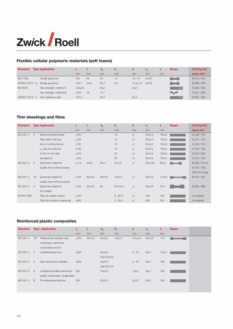
Flexible cellular polymeric materials (soft foams)
Standard Type Application l3 l1 b2 b1 h L0 L Shape Cutting die/
mm mm mm mm mm mm mm spare die1)
ISO 1798 Tensile specimen 152 55 25 13 10...15 25/50 - B.015 / 016
ASTM D 3574 - E Tensile specimen 139.7 34.9 25.4 6.4 12.5±1.5 20/25 B.039 / 040
ISO 8067 Tear strength, method A 125±25 25±1 25±1 D.093 / 094
Tear strength, method B >_100 19 12.7 - D.001 / 002
ASTM D 3574 - F Tear resistance test 152.4 25.4 25.4 D.081 / 082
Reinforced plastic composites
Standard Type Application l3 l1 b2 b1 h L0 L Shape
mm mm mm mm mm mm mm
ISO 527-4 1B Preferred for isotropic and >_150 60±0.5 20±0.2 10±0.2 4.0±0.2 50±0.5 115
orthotropic reinforced
composites and for
ISO 527-4 2 multidirectional and >_250 25±0.5 2...10 50±1 150±1
oder 50±0.5
ISO 527-4 3 fibre-reinforced materials >_250 25±0.5 2...10 50±1 136
oder 50±0.5
ISO 527-5 A Unidirectional fibre-reinforced 250 15±0.5 1±0.2 50±1 136
plastic composites, longitudinal
ISO 527-5 B For transverse direction 250 25±0.5 2±0.2 50±1 136
Thin sheetings and films
Standard Type Application l3 l1 b2 b1 h L0 L Shape Cutting die/
mm mm mm mm mm mm mm spare die1)
ISO 527-3 2 Recommended shape. <_150 10 <_1 50±0.5 100±5 A.149 / 150
Strip taken with any <_150 12 <_1 50±0.5 100±5 A.121 / 122
kind of cutting device. <_150 13 <_1 50±0.5 100±5 A.123 / 124
L0 may be reduced <_150 15 <_1 50±0.5 100±5 A.125 / 126
to 50 mm for high <_150 20 <_1 50±0.5 100±5 A.079 / 080
elongations <_150 25 <_1 50±0.5 100±5 A.127 / 128
ISO 527-3 5 Specimen shape for >_115 33±2 25±1 6 ±0.4 <_1 25±0.25 80±5 B.009 / 010 or
quality and control purpose B.125 / 126
(130 mm long)
ISO 527-3 1B Specimen shape for >_150 60±0.5 20±0.5 10±0.2 <_1 50±0.5 115±5 B.019 / 020
quality and control purpose
ISO 527-3 4 Specimen shape for >_152 50±0.5 38 25.4±0.1 <_1 50±0.5 73.4 B.085 / 086
thin sheets
ASTM D 882 Strip for quality control >_150 5...25.4 <_1 100 100 on request
Strip für modulus measuring >_300 5...25.4 <_1 250 250 on request

15
Specimen for pendulum impact tests
Standard Type Application l3 l1 b2 b1 h L0 L Shape Cutting die/
mm mm mm mm mm mm mm spare die1)
ISO 179-1 1 Charpy (from multipurpose 80±2 - - 10±0.2 4±0.2 62+0.5 only molding
specimen) (preferred) or machining
ISO 179-1 2 Charpy, materials exhibiting 25 x h - - 10 or 15 3 (preferred)20 x h -
3 interlaminar shear (11 or 13) x h - 10 or 15 3 (preferred)(6 or 8) x h -
ASTM D 6110 - Charpy, notched specimen 127 63.5 - 12.7 3...12.7 101.6±0.5 molded or
(5‘‘) (2.5‘‘) (1‘‘) 6.36...12.7 (4‘‘) pressed
(preferred)
ISO 180 1 Izod (from multipurpose 80±2 - - 10±0.2 4±0.2 - -
specimen)
ASTM D 256 - Izod, notched specimen 63.5±2 - - 12.7±0.2 3...12.7 31.8±1 -
(2.5‘‘) (0.5‘‘) 6.35...12.7 (1.25‘‘)
(preferred)
ASTM D 4812 - Cantilever Beam Impact 63.5 - - 12.7 3.17 ±0.13 - -
(unnotched) (2.5‘‘) (0.5‘‘) (preferred)
ASTM D 4508 - Chip impact 19.05 - - 12.7 1.02...3.175 - -
(small specimen) (0.75‘‘) (0.5‘‘) (0.04‘‘...0.125‘‘)
DIN 53435 - Dynstat impact 15 ±1 - - 10 ±0.5 1.2...4.5 -
(small specimen)
ISO 8256 1 Tensile impact, notched type 80±2 30±2 10±0.5 6±0.2 - D.095 / 096
2 Tensile impact 60±1 25±2 10±0.2 3±0.05 10±0.2 D.101 / 102
3 Tensile impact 80±2 30±2 15±0.5 10±0.5 10±0.2 D.103 / 104
4 Tensile impact 60±1 25±2 10±0.2 3±0.1 - D.097 / 098
5 Tensile impact 80±2 50±0.5 15±0.5 5±0.5 10±0.2 D.105 / 106
ASTM S Tensile impact 63.5 25.4 9.53/12.7 3.18±0.03 3.2 - D.087 / 088
D 1822M L Tensile impact 63.5 25.4 9.53/12.7 3.18±0.03 3.2 - D.090 / 100
(2.5‘‘) (1‘‘) (0.125‘‘) (0.125‘‘)
Plastic piping
Standard Type Application l3 l1 b2 b1 h L0 L Shape Cutting die/
mm mm mm mm mm mm mm spare die1)
PVC-Pipes
ISO 6259-2 1 Machined specimen >_115 33±2 >_15 6+0.4 wall thickness 25±1 80±5
ISO 6259-2 2 By cutting die >_115 33±2 25±1 6+0.4 wall thickness 25±1 80±5 B009 / 010
produced specimen
Polyolefin pipes (PE, PP)
ISO 6259-3 1 Wall thickness >5 mm >_115 60±0.5 20±0.2 10±0.2 wall thickness 50±0.5 115±0.5
(similiar ISO 527-2, type 1B)
ISO 6259-3 2 Wall thickness <_5 mm >_115 33±2 25±1 6+0.4 wall thickness 25±1 80±5 B009 / 010
(similiar ISO 37, type 1)
ISO 6259-3 3 Wall thickness >12 mm >_250 25±1 100±3 25±1 wall thickness 20±1 165±5

16
Dimension measurement
The reproducibility of test results issignificantly influenced by accurateand reproducible measurement ofthe specimen dimensions.
Methods for determining the relevantdimensions are defined in Standards.
Vernier calliper
Vernier callipers can be used todetermine dimensions of >_ 30 mm onplastics and rubbers (see ISO 178,ISO 4648, ASTM D 3767, DIN 53534),and dimensions >_ 10 mm of rigidcellular plastics (DIN 53570)
Dead weight thickness gauge providing aconstant measuring force(DM-THICKGA.00 + DM-PLASTFOI.S00)
Requirements of standards for measurements by use of a micrometeror an automatic cross-section measuring device
Standard Material Test type Measurement of Reading req.
ISO 527-1 Rigid and semi-rigid plastics Tensile Thickness, width <_0.020 mmASTM D 638 Rigid and semi-rigid plastics Tensile Thickness, width <_0.025 mmISO 178 Rigid and semi-rigid plastics Flexural Thickness, width <_0.010 mmASTM D 790 Rigid and semi-rigid plastics Flexural Thickness, width <_0.010 mmASTM D 374 Plastic sheet and film General Thickness >0,25mm <_0.010 mmISO 1923 Rigid cellular plastics General Dimensions <_10 mm <_0.05 mm
Digital micrometerswith ratchet
Micrometers, able to generate aconstant measuring force, aresuitable for dimensions >_ 0.25 mmof rigid and semi-rigid plastics.
Both vernier callipers and micro-meters can be connected via RS232interface to the PC. Multiplexers for2, 3 or 6 measurement devices arealso available.
Digital hand micrometer (Ref. W40032)Digital vernier calliper (Ref. W40031)
Dead weight thicknessgauges
are used to measure the dimensionsof rubbers, elastomers, non-rigidplastics, flexible cellular plastics, thinsheetings and plastic films.
As the surface pressure applied on thetest piece by the thickness gauge isimportant for accurate measurement,the testing Standards fix the shapeand surface-area of contacting sur-faces such as the pressure foot andthe anvil as well as the weight to beapplied. Various contact elementscan be used with the same device.
A choice of standards and contactelements is shown on the next page.
Reference THICK THICK
GA.000 GA.H00
Range: 12 mm 12 mm
Resolution: 1 µm 0.2 µm
Anvil dia.: 50 mm 50 mm
Connection: Multiplexer RS 232
Reference W40032
Range: 0 to 25 mm
Contact surface, shape: circular/flat
Contact surface diameter: 6.35 mm
Measuring force: 5 to 10 N
Display resolution: 0.001 mm
Reference Range Resolution
W40031 150 mm 0.01 mm
W40038 500 mm 0.01 mm

17
Requirements of standards – Measurement carried out by use of dead weight thickness gauges
Standard Material Test- Specimen Measure- Pressure- Pressure- Anvil Contact Contact Reso- Recomm.type ment of foot, shape foot, diam. diam. pressure force lution contact elem.
mm mm kPa N mm Reference
ISO 37 Rubber Tensile Dumbbell Width (nominal distance between cutting edges)Rubber Tensile Ring Thickness circul./flat (same device as for dumbbell test pieces)
Tensile Ring Rad. Width 2 cylinders on request
ISO 4648/ Rubber/ Tensile 1 / (S1) Thickn.<30 circul./flat 10 >10 10±2 0.562 0.001
DIN 53534 IRHD<35 Tensile 2 / (S2) Thickn.<30 circul./flat 10 >10 10±2 0.388 0.001
Tensile 3 / (S3a) Thickn.<30 circul./flat 10 >10 10±2 0.388 0.001
Tensile 4 / (S3)*) Thickn.<30 circul./flat 10 >10 10±2 0.201 0.001
larger
specimen*) Thickn.<30 circul./flat 6 >6 10±2 0.282 0.001 DM-
IRHD>_35 Tensile 1 / (S1) Thickn.<30 circul./flat 10 >10 22±5 1.236 0.001 ELASTOM.S00
Tensile 2 / (S2) Thickn.<30 circul./flat 10 >10 22±5 0.853 0.001
Tensile 3 / (S3a) Thickn.<30 circul./flat 10 >10 22±5 0.853 0.001
Tensile 4 / (S3) Thickn.<30 circul./flat 10 >10 22±5 0.441 0.001
larger
specimen Thickn.<30 circul./flat 6 >6 22±2 0.622 0.001
ASTM D412/ Rubber/ Tensile Dumbbell Thickn.<_30 circul./flat 3...10 35 10±2 - 0.001
ASTM D3767 IRHD<_35 Tensile Dumbbell Width (nominal distance between cutting edges)
IRHD>35 Tensile Dumbbell Thickn.<_30 circul./flat 3...10 >_35 22±5 - 0.001 DM-
IRHD<_35 Tensile Ring Thickn.<_30 circul./flat 3...10 >_35 10±2 - 0.001 ELASTOM.S00
IRHD>35 Tensile Ring Thickn.<_30 circul./flat 3...10 >_35 22±5 - 0.001
alle IRHD Tensile Ring Rad. width 2 cylinders 15.5±0.5 (length 12mm) on request
ASTM D374 Shore A General All types Thickness circul./flat 6.35±0.25 >_50 26±4 - 0.002 on request
30 to 80 0.76...6.35
ASTM D3767 Rubber Compr. Thickness spherical 9.5...10 0.8±0.1 - on request
set plot (Spheric rad. 12.5±0.1)
ISO 527-1 Non-rigid Tensile Dumbbell Thickness circul./flat - - 20±3 - 0.02 DM-
plastics Tensile Dumbbell Width circul./flat - - 20±3 - 0.1 PLASTFOI.S00
ASTM D 638 Non-rigid Tensile Dumbbell Thickness circul./flat 6.35±0.025 >6.4 25±2.5 - on request
plastics Tensile Dumbbell Width circul./flat 6.35±0.025 >6.4 25±2.5 - -
Tensile Large spec. Thickness circul./flat 15.88±0.08 >6 25±2.5 - -
ISO 527-3/ Sheet & Tensile Strip & Thickness circul./flat 2.5...10 2.5...10 0.5...1 -0.001 DM-
ISO 4593 film Tensile Dumbbell >_10 µm PLASTFOI.S00
Tensile Width (nominal distance between cutting edges)
ASTM D882 Sheet & Tensile Strip & Thickness circul./flat 25...55 3...13 >_51 0.0025 DM-
film Dumbbell >_0,025...to 0,25 PLASTFOI.S00
ASTM D374 Sheet & General All types Thickness circul./flat 25...55 3...13 >_51 0.002 DM-
film >_0,025...0,25 PLASTFOI.S00
ISO 1923/ Cellular General All types Dimensions circul./flat 35.7 >36 0.1±0.01 - 0.05 on requestDIN 53570 plastics >_10 mm
*) Measurement only with thickness gauge DM-THICKGA.H00
Remark: Standards for elastomers and rubbers generally require the median of 3 measurements.Standards for plastics generally require the average of 3 measurements.Standards for cellular plastics generally require the average of 5 measurements.

18
Material testingmachines
Zwick produces material testingmachines with capacities up to6000 kN and sometimes more. Forplastic materials and rubbers mostof the standard tests are covered byforces up to 20 kN.
Typical fields of application
Loads up to 1 kN• Tensile and tear tests on rubbers,
non-rigid plastics, thin sheets andfilm, cellular plastics
• Creep and flexural tests on rigidand semi-rigid plastics
• Peel resistance of adhesives
Loads up to 10 kN• Indentation hardness and com-
pression tests on cellular plastics
Loads up to 20 kN• Tensile, compression, creep and
shear tests on rigid and semi-rigidplastics
Loads higher than 20 kN• Tensile and compression
properties of reinforced plasticcomposites
• Compression properties of plasticpiping as well as other plastic andrubber parts
Basic concept
In order to be able to offer the bestmachine for each requirement,Zwick‘s comprehensive productrange includes three machineversions for static materials testing,each of them offering differentequipment, performance andexpansion capabilities:
Automatic cross-section measuring device(Ref. 066998.00.00)
Automatic cross-sectionmeasurement device
Automatic cross-section measure-ment devices are used for fast, com-fortable and reproducible measure-ment of specimen thickness, widthor diameter on rigid and semi-rigidplastics.
The operator places the specimeninto the measurement device whereone or several measurements canbe carried out. By this method, theinfluence of the operator on thespecimen dimension measurementis eliminated.
Available balances
Reference W4002-2.01.00 2.02.00 3.01.00
Meas. range <_51 g <_101 g <_151 g
Resolution 0.1 mg 0.1 mg 1 mg
PC-connec. RS232 RS232 RS232
Power supply 220 V 220 V 220 V
Digital balance and kit for the determinationof density, gravimetric method, (4106.69)
Measurement of crosssection by weight
This method is used for the cross-section determination of rubber andelastomer ring specimens as well asfor strip specimens of very thin(<_ 10 µm) or embossed plastic film.
Determination of ambientdensity according toISO 1183, DIN 53479-A
The method consists of weighingthe material in air and in distilledwater, normally at ambient temper-ature. The kit consists of weighingmechanism and a thermometer.A suitable balance is needed.
Reference 066998.00.00
Shoulder width, max: 40 mm
Parallel length, min: 60 mm
Specimen length, min: 100 mm
Thickness, range: 0.1 to 20 mm
Thickness, contact foot: spherical
Width/diameter, range: 6.0 to 40 mm
Width, contact foot shope: flat, Ø 1 mm
Resolution: 0.001 mm
Accuracy (gauge block): ± 0.003 mm
PC-Connection: RS 232
including certified gauge block.

19
• The ProLine is particularlysuitable for functional tests oncomponent parts as well as forstandard materials tests. A broadrange of standard accessoriesprovides comprehensive testingcapability at an affordable price.
• The zwicki-Line consists of top-quality space-saving testing ma-chines. These simple-to-use andeasy-to-transport single columnmachines have been designed fortest forces up to a maximum of5 kN.
• The Allround-Line is theflagship-range of testingequipment offering the highestlevel of technical sophisticationand future expansion possibilities.
Measurement and controlsystem
The fundamental component for anytesting machine is the measure-ment and control system. Its designand scope of capabilities determinewhich drive system it can regulate,which measurement system it isconnected to and which functionscan be controlled.
The testControl controller offershighest technical performance andlong range return of investmentthrough the use of the latesttechnologies and highest qualitystandards. Notable characteristicsof the electronics are:
• Chronologically-synchronized testdata recording with high resolutionand measurement frequency
• Sampling of input signal at 320 kHz
• 500 Hz real-time processing ofthe test data for monitoring andevent oriented control of the testsequence and for safety limits.(e.g. speed change upon reachingthe yield or proof stress limit)
• Adaptive control for precise andreproducible speeds and positions
testControl and hence the testingmachine, is operated by using a PCand the test software testXpert® II.The system is easy to configure andupgrade for almost any diverseapplication as well as extremelyflexible and easy to operate.
The optional stand-alone variantoffers simple, direct operation of thetesting machine without a PC, usinga colour display, a key pad and afew, intuitive function keys. A printercan be connected to output the testresults.
Materials testing:Tensile test according to ISO 527-2
Components testing with ProLine:Determination of the stiffness of window frames

20
Alround-Line Z010 equipped for tensiletesting
zwicki-Line materials testing machines for materials and components testing
Load frames
Different load frame versions areavailable for test loads up to 2000 kNas standard. Special applicationscan be developed and manufactured,for example, load frames inhorizontal posi-tion suitable for thetesting of long ropes.
Table-top testing machines,zwicki-Line
These single column load framesare designed with very rigidaluminium high-precision extrudedprofiles. The working area is freelyaccessible from 3 sides. It onlyrequires limited bench space andfits on most laboratory tables. Dueto its low weight, it is easy totransport.
Table-top testing machines,ProLine
The load frames of the ProLine aredesigned with twin lead screws and2 round steel columns ensuringprecise guidance of the movingcrosshead. The integrated protec-tion of lead screws and guidecolumns aids reliable testing evenfor very brittle materials.
zwicki-Line load frames and drives
Series Z0.5 Z1.0 Z2.5 Z5.0• Max. test load [kN] 0.5 1.0 2.5 5.0
• Work space height* short [mm] 570 570 573 -
* normal [mm] 1070 1070 1073 1030
* high [mm] 1370 1373 1373 -
• Work space width [mm] 4 4 4 4
• Work space depth [mm] 100 100 100 100
• Max. crosshead speed [mm/min] 2000/3000 2000 1000 600
• Crosshead travel resolution [µm] 0.2453 0.2265 0.0996 0.0399
• Max. power consumption, kVA 0.44 0.44 0.44 0.44
21
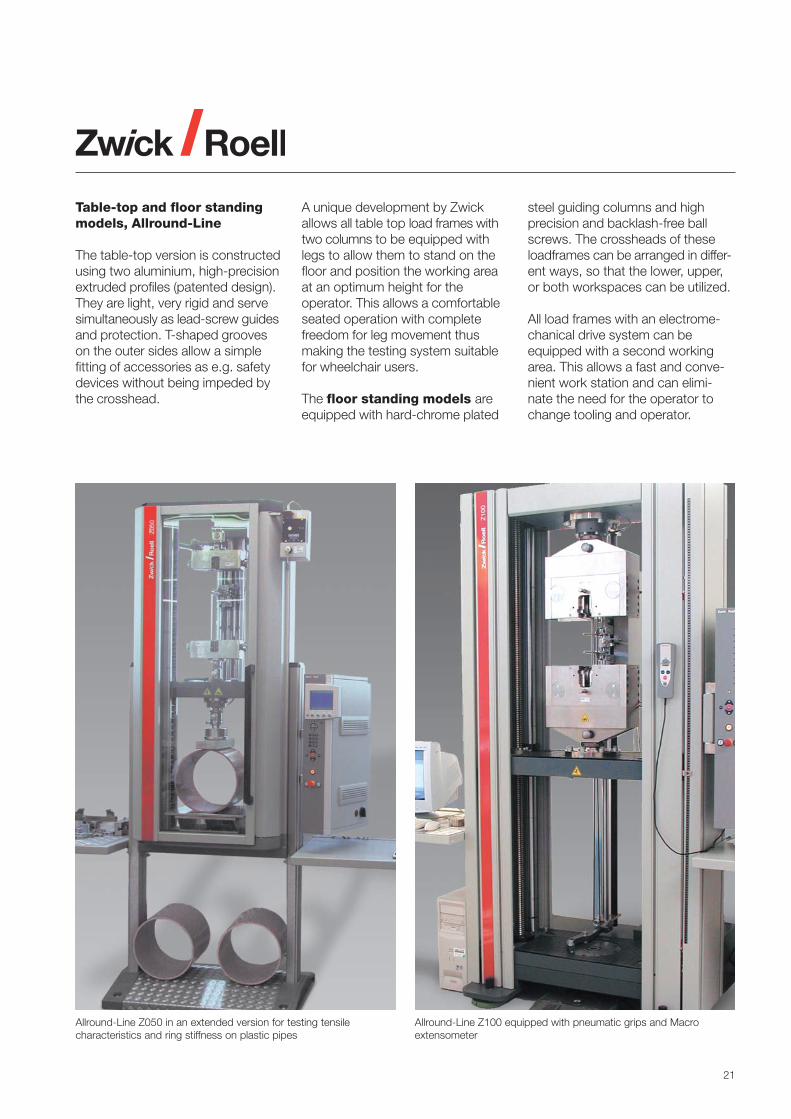
Allround-Line Z050 in an extended version for testing tensilecharacteristics and ring stiffness on plastic pipes
Allround-Line Z100 equipped with pneumatic grips and Macroextensometer
Table-top and floor standingmodels, Allround-Line
The table-top version is constructedusing two aluminium, high-precisionextruded profiles (patented design).They are light, very rigid and servesimultaneously as lead-screw guidesand protection. T-shaped grooveson the outer sides allow a simplefitting of accessories as e.g. safetydevices without being impeded bythe crosshead.
A unique development by Zwickallows all table top load frames withtwo columns to be equipped withlegs to allow them to stand on thefloor and position the working areaat an optimum height for theoperator. This allows a comfortableseated operation with completefreedom for leg movement thusmaking the testing system suitablefor wheelchair users.
The floor standing models areequipped with hard-chrome plated
steel guiding columns and highprecision and backlash-free ballscrews. The crossheads of theseloadframes can be arranged in differ-ent ways, so that the lower, upper,or both workspaces can be utilized.
All load frames with an electrome-chanical drive system can beequipped with a second workingarea. This allows a fast and conve-nient work station and can elimi-nate the need for the operator tochange tooling and operator.

22
The C-frame is used for compression and indentation hardness tests of large foam parts
Loadframes for testingsoft foams
Specific loadframes are availableto test large foam parts such asseat cushions, matresses etc.
The C-frame
With this type of loadframe lateraltables can be raised on both sidesin order to get a large anvil surface.Optionally, this frame can be equip-ped by a sliding-support which is use-ful for testing large matresses. In thetest area the table is perforated withholes to allow rapid air escape duringindentation tests, as described inmany ISO, ASTM standards andautomotive specifications.
The test space is accessible fromthree sides to allow a very practical
and fast operation. By use of adap-tors, this load frame can be used fortensile and tear testing as well.
Lower testing platform
Several types of standard loadframescan be equipped with a lower testingplatform (see below right) that allowstesting of larger foam parts, but main-tains the functionality of the loadframe itself.
Constant load pounding machine
This machine type is equipped with ahigh-speed electromechanical drivesystem to generate the constantload pounding frequency requiredby the testing standards. In addition,this machine can also be used forstatic compression and indentationhardness tests.
This machine can be used for constant loadpounding tests as well as for staticcompression and indentation hardness
Testing of larger parts can be performed inthe optional lower testing platform

23
ProLine Load Frames and Drives
Tabletop Testing MachinesSeries Z005 Z010 Z020 Z030 Z0501) Z100• Max. test load [kN] 5 10 20 30 50 100• Work space height
* shortened [mm] 570 - - - - -* normal [mm] 1070 1050 1050 1370 1370 1360* increased [mm] - - - - - -
• Work space width [mm] 440 440 440 440 440 640• Work space depth [mm] 4 4 4 4 4 4
• Max. crosshead speed [mm/min] 500 1000 500 300 180/6001) 300• Crosshead travel resolution [µm] 0.039 0.038 0.018 0.012 0.007/0.0161) 0.008• Max. power consumption, kVA 0.8 0.8 0.8 0.8 0.8/31) 3
1) This testing machine is available in two electronics variations. The first value is for the standard electronics, the second for testControl.
Allround-Line Load Frames and Drives
Tabletop Testing MachinesSeries Z005 Z010 Z020 Z030 Z050 Z100 Z150• Max. test load [kN] 5 10 20 30 50 100 150• Work space height
* normal [mm] 2) 1045/1025 1045/1025 1045/1025 - - - -* increased [mm] 2) 1445/1425 1445/1425 1445/1425 1355/1325 1355/1325 1355 1535* extra high [mm] 2) 1795/1785 1795/1785 1795/1785 1755/1725 1755/1725 1755 -
• Work space width* normal [mm] 440 440 440 440 440 - -* widened [mm] 640 640 640 640 640 640 640
• Work space depth [mm] 4 4 4 4 4 4 4
• Max. crosshead speed [mm/min] 3000 2000 1000/20003) 1000 600 750/15003) 900• Crosshead travel resolution [µm] 0.0410 0.0272 0.0136/0.05433) 0.0271 0.0163 0.0207 0.0123• Max. power consumption, kVA 2 1.9 2.1/2.63) 2.3 2.3 4/63) 5.5
Floor-standing Testing MachinesSeries Z050 Z100 Z150 Z250 Z300 Z400 Z600• Max. test load [kN] 50 100 150 250 300 400 600• Work space height[mm] 1825/17602) 1825/17602) 1715/16552) 1715/16552); 1800 1800 1940
13604)
• Work space width* normal [mm] 630 630 630 630 630 630 740* widened [mm] 1030 1030 1030 1030 - - -
• Work space depth [mm] 4 4 4 4 4 4 4
• Max. crosshead speed [mm/min] 1000/20003) 500/10003) 900 600 250 250 200• Crosshead travel resolution [µm] 0.0270 0.0136 0.0123 0.0082 0.031 0.031 0.025• Max. power consumption, kVA 4/53) 4/53) 5.5 6 7/135) 7/135) 20/265)
2) The second value is for the model with the widened work space 3) Depending on selected drive and its power4) The last value is for a cost effective special model limited to one work space 5) Higher power consumption applies for hydraulic grips

24
testXpert® II – Intelligentand Reliable, the NewSoftware Generation forMaterials Testing
Zwick Roell has set new standardswith testXpert® for intelligent materialstesting software. Unlike other software,Zwick has standardized testXpert®
for all of its applications, no matterwhether static or dynamic tests – soyou spend less time learning to handlesoftware and more time conductingtests. With testXpert® II, you benefitfrom over 80 years of testingexperience and from over 10,000successful installations worldwide.
Some Significant Benefitsof testXpert® II
Ingeniously simple – testXpert® IIis organized so that you can oper-ate it intuitively. Expressive symbolsand a clear menu structure enablequick familiarization. The menu baris set up according to the needs ofthe user, making working withtestXpert® II ingeniously simple.
Intelligent – Wizards help you toset up or change test proceduresand test reports. Should you haveany questions, the extensive contextsensitive online help feature willquickly deliver the answer.
Modular design – means thatspecific testing solutions meet yourparticular requirements. Additionaltesting capabilities can be added asneeded.
Compatible with your hardware –Zwick testXpert® II is compatible withall commercially available PCs andlaptops without the need for an addi-tional interface card! This means it iseasy to switch system computers oreven to develop test methods or per-form analyses in the office at yourconvenience. You always have ac-cess to your test data.
Online language swapping –Needless to say, you can havetestXpert® II in your language ofchoice. testXpert® II speaks morethan one language – all you need todo is click the mouse in order tochange the language online. Lan-guage swapping is a function whichcan be changed at any time, e.g.,when generating the test report. Fle-xible testXpert® II language swappingoffers international teams not onlylanguage-neutral operation of theirtesting machine but also consider-ably simplified communication.

25
Industry-oriented terminologyand data export capability –And testXpert® II not only uses yourlanguage but it also adopts yourtechnical terminology. For example,symbols or variables that are specificto your industry (e.g., metals, plastics,rubber) are implemented throughoutthe software. This provides more re-levant meaningful information for yourtesting application. Today’s qualityassurance standards necessitatethat the test results may be expor-ted to a company’s central labora-tory database. So we have createdtestXpert® II to communicate reliablywith your IT system by providing flexi-ble interfaces and MS Office integra-tion by means of Object LinkingEditing (OLE).
Select Test StandardIn testXpert® II you find the rightstandard for every test. Just selectthe desired test program. All para-meters are preconfigured to stan-dard. You can of course adjust theseif you wish.
TestThe individual data are displayed onthe monitor – online as part of thetest procedure. You can follow thetest procedure live. If desired youcan also incorporate an exactlysynchronized video recording.
Comparison of measured and nominal strain during a tensile test acc. ISO 527-2
The results are already calculatedduring the test so that the test pro-cedure can be eventmanaged, e.g.,by speed change after determiningthe E-modulus or the yield point.Only in this manner can the test beperformed quickly and according tostandard.
Evaluation of Test ResultsIn testXpert® II you can create manydifferent screen layouts according toyour needs. For example: With othergraphs, various representations ofthe testing curves, tables and additi-onal statistics. With one click youcan switch between the various lay-outs, thus changing the representa-tion of your test results.
For processing the test resultstestXpert® II offers a variety of tools:e.g., the report editor for creating anindividual test report, or various ex-port possibilities, e.g., in Excel orWord.

26
The video pictures and the data curves are exactly synchronized with each other. Themeasured data points and specimen behaviour are then easily compared
A representation of a material’s tensile strength over a period of days
Synchronized video recording –testXpert® II offers you an image-for-image, perfectly synchronized videorecording of your test. You can inter-pret the measuring curve of the testefficiently with the help of the recor-ded image changes of the specimen.You can record the test procedurewith a video camera or an USBwebcam. And testXpert® II saves therecorded images synchronized withthe measuring data. The visual recor-ding shows, for example, when, how,and where the specimen necks,buckles, or changes colors. The al-terations in specimen dimensionscan be measured exactly from thecaptured images. In addition, beforethe test, you can determine whichevents images should be recordedfor: such as the point in a cycle whencompression switches over into ten-sile stress. Afterwards you can printout these pictures or integrate theminto the test report. Thanks to thesynchronized video recording, thetest procedure can be recalled orcompared at any later time.
testXpert® II LIMS –Only testXpert® II offers these fea-tures: an integrated Laboratory Infor-mation Management System (LIMS).A powerful database is available toadminister your test results in orderto create and archive long-term sta-tistics and reports. All data acquiredby testXpert® II are available fromany testing system in your company.

27
An example of a graphical sequence editor program
The program sequence is illustrated. Details for each step may be shown and changed by clicking on the respective boxes.
Graphical Sequence Editor –The testXpert® II Graphical SequenceEditor offers all the freedom you couldpossibly hope for. It enables you todesign test procedures of any kindindividually, by combining testevents, parameters and results ex-actly as you require. The intelligentconstruction of the graphical-userinterface allows the editor to makeyour work easy. You do not requireany programming knowledge: Thegraphic user interface makes for quickfamiliarization with the functionality.The integrated simulation modeoffers you safety: It analyzes the testprocedure you have created incor-porating a virtual testing machine,with different specimen behaviour(e.g. spring, plastic, metal, etc.). Youthus filter out errors from the testprocedure in the early stages, and allthis without destroying a singlespecimen.
Example: You want to cycle betweentwo steps (such as load levels) withina test sequence. Use the mouse toselect the module of the first step anddrag and drop it into the sequence.Decide the parameters for the firststep. Proceed accordingly with the
second step. You can enter thenumber of loops in the loop moduleunderneath it, and then reconnect itto the beginning. At the same time,a limit can be monitored during thisprocess. Once again, very simply, byselecting the respective limit module.

28
Type/test conditions RT RS SB BBTension force with axial load application + + + + + + + + + + + +
Compressive force with safe axial load application + + + + + + + + +Compressive force with excentric load application + + + - 1) - 2) - 2)
Bending tests + + + + + + + + +Extended temperature range + + + + + + + + +Creep tests + + + + + + + + +Axial alignment under load + + + + + + + + +
1) Limited measuring accuracy 2) Risk of destruction
Intelligent Load cells
Load cells are available for accurateload measurement of forces from0.04 N onwards. They offer thefollowing advantages in conjunctionwith the digital measurementelectronics:• Automatic identification and
acquisition of all setting andcalibration parameters via sensorplug. An exchange of the load cellsneither requires a calibration nor amodification of the setting data.
• Automatic zero-point andsensitivity balancing
• Temperature compensation• High measurement frequency• Very high test data resolution• Accuracy:
Class 1 (1 % of reading)from 0.2 to 120 % of full scale load(1 to 100 % in the case of loadcells smaller than 500 N).Class 0.5 (0.5 % of reading) from1 % to 100 % of full scale load.
• Overload protection• Manufacturer’s test certificate
to certify the factory calibration
Load cells with one or two sidedmounting stud and self-identifyingsensor plugs are available for loadcapacities from 10 N upwards.
Types and recommendationsfor their use
Depending on the test, theaccuracy of the load cells and otherfeatures are important. For use with
temperature devices, these are thetemperature sensitivity of zero-pointand measured value. During com-pression and flexural tests, trans-verse forces and moments mayoccur which should not falsify theforce value in an inadmissible wayand which should not damage theload cell. For this reason, Zwickoffers different types of load cells.
• Load cell type ring-torsionThe body of this circular load cellis a bending ring with ring-shapedstrain gauges on the face sides.It is very insensitive to excentricload applications and overloads.
• Load cell type ring-spokesThe outer and the inner ring ofthis load cell are linked by spokeson which the strain gages areapplied to. This load cell is rela-tively insensitive to excentric loadapplications.
Load cell with sensor plug, type ring-torsion
• Load cell type S-beamThe body of this flat, S-shapedload cell is a double beam. It isrelatively sensitive to excentricload applications.
• Load cell type beam barThis load cell consists of a doublebeam-shaped body. The centri-cally acting test load is traversedlaterally and transmitted to thecrosshead of the testing machine.Therefore it is quite sensitive toexcentric load applications.
Note:The measurement body of the load cell isillustrated in dark blue and the strain gaugesapplied onto them are illustrated in red.

29
SpecimenGrips and Tooling
Specimen grips for tensile,creep and cyclic tests
Zwick offers a large product rangeof specimen grips in various designs,test load ranges and test tempera-tures to cover the wide range ofapplications for the plastics andrubber testing (see table “selectioncriteria for specimen grips”).
The specific range of application of aspecimen grip depends on the oper-ating principle and the maximumpermissible test load. For tests insidea temperature or climatic chamber,the temperature range is anotherimportant factor.
Force transfer betweenspecimen and specimen grips
The clamping principle defines thetype of force transfer betweenspecimen and specimen grips. Mostgrips are named according to theirclamping principle.
For the majority of specimens, thetest load can only be transferred by aforce-holding gripping principle, i.e.friction. The frictional force betweenspecimen ends and gripping jaws ofthe specimen grips must always begreater than the test load. The re-quired gripping forces acting verticallyto the test load are generated exter-nally (e.g. by means of pneumaticpressure) or are generated mechani-cally from the test load (e.g. by meansof sliding wedges).
In order to avoid specimen breakwithin the grips – particularly forgripping-sensitive and flexible speci-mens (plastic films, strips, mono-filaments) – the test load is slightlyreduced by a frictional force appliedby wrapping around prior to gripping.For this purpose, the specimen endsare wound onto cam plates and aresubsequently clamped.
For rubber ring specimens, the forceis transferred according to the form-fitting gripping principle. They arewound over pulleys.
Gripping force
For specimen grips with an externalgripping force application, e.g.hydraulic, motorized, pneumatic, theset gripping force is effective duringthe entire test. When testing thickand soft specimens, specimenmaterial may flow out of the grippingrange (slip) during load applicationcausing a reduction of the specimenthickness. When using hydraulic orpneumatic specimen grips, thegripping force remains constant
because the pressure generatormaintains the oil or compressed airpressure. When using screw grips,the gripping pressure is reduced inaccordance to the rigidity and theresilience of the specimen grip.
Due to the high gripping force ofthese specimen grips, specimenmaterial is “pushed” out of thegripping range while closing thegrips. The specimen is compressedand may be damaged. This effectcan be avoided by activating themachine drive during the closureof the clamps. (“Zero-Force-Regulation”).
In case of self-clamping grips, theinitially low gripping force increasesin relation to the acting tensile forceand the function principle of thegrips (Wedge, pincer, etc.).
Gripping surfaces
The frictional force depends not onlyon the gripping force, but also onthe coefficient of friction of thecontacting surfaces. For this reason,exchangeable gripping jaws or jawfaces with different surface types(shape, surface structure, materialetc.) are availalable for many speci-men grips.
Gripping travel and openingwidthSpecimen grips with an externalgripping force application havea long gripping travel and conse-quently a large opening width. Thismeans an easy specimen feed evenwhen testing thicker specimens.Exchangeable gripping jaws fordifferent specimen thicknesses arenot required.
Clamping force
Tensile force
Hydr. and pneum. grips
Screw grips
Wedge-screw grips
Wedge grips
Pincer grips
Dependence of the clamping force on thetest load for different types of specimen grips

30
When using self-clamping grips,each change of the gripping travelcauses a larger displacement ofthe jaws in. Therefore, grippingtravel, opening width and thus therange of specimen thicknesses andthickness variations are limited forthese types of specimen grips.Differently thick gripping jaws mightbe required to cope with differentthickness ranges.
Gripping jaw tracking action
During the test, the specimen thick-ness may be reduced in proportionto the increase in test load; this isparticularly the case when testingthick and soft specimens. Thischange in thickness has to be com-pensated by an additional grippingtravel. For self-clamping grips, thegripping jaws are moved towardsthe center of the specimen. Thisgripping jaw tracking action whichis considerably greater than thechanging thickness of the specimen(for wedge grips with a wedge angleof 15 degrees, a change in thick-ness of 0.1 mm causes a gripping
jaw tracking action of about 1 mmat both ends of the specimen!)results in a corresponding error ofthe indirect extension measurementfor the determination of the nominalstrain.
Handling and control
The opening and closing of thespecimen grips for low test loadsis mostly done via lever or hand-wheel.
When using specimen grips forhigher test loads and frequent op-eration, the manual operation canbe very tiring for the operator. In thiscase hydraulic, pneumatic or motor-ized grips which are operated viapush buttons or foot switch are agood solution. In case of semi-automatic operations, the user onlyhas to close the specimen grips.Depending on the specimen dimen-sions, it is even possible to set thehydraulic or pneumatic pressure –and thus the gripping force – auto-matically. The opening is doneautomatically after the specimenbreak.
Types of specimen holders
Hydraulic grips
These universall grips are predomi-nantly used for average and hightest loads. The gripping force isapplied via direct acting hydrauliccylinder. The grips are available intwo versions:
• One manually adjustable and onehydraulic operated grip jaw soshear tests with an excentricgripping can also be performed.
• Symmetrical jaw closing
The required hydraulic energy issupplied by a hydraulic unit(see photo: hydraulic grips).
Pneumatic grips
Depending on the clamping forcerequired, these grips incorporatedirect acting pneumatic cylinders orapply the clamping force via al leversystem. They are mainly used forlow and average test loads.
Versions with single or double-sidedclosing gripping jaws are available.The required pneumatic energy ismostly supplied by the in-housecompressed air ductwork system(see photo: pneumatic grips).
Gripping process for specimen grips withexternal load application (long grippingtravel, no gripping jaw tracking action)
Gripping process for increasing force wedgegrips (short gripping travel, large gripping jawtracking action)
Open Closed Loaded
Pneumatic grips
Open Closed Loaded
Grip
ping
trav
el
Jaw
trac
king
act
ion
Hydraulic grips

31
Wedge-screw grips
These specimen grips are a com-bination of screw and wedge grips.With the screw drive, the grippingjaws are closed and opened – andthe initial gripping force is generated.If the clamp is closed, the wedgesgenerate the increasing force effect.
Optionally, the screw drive can eitherbe driven by motor, be controlledmanually via push buttons or exter-nally by electronic/PC.
Screw grips
One gripping jaw is operated manu-ally via screw drive. The other grip-ping jaw can be set in fixed steps,steplessly or may be permanentlyfixed.
Screw grips
Wedge grips
Wedge-Screw grips
Pincer grips
This pincer-type specimen grip alsohas the increasing force principle.The initial gripping force is appliedby a prestressed spring. The pincerprinciple generates a gripping forcewhich increases exponentially to thetensile force. It is particularly suit-able for tensile specimens made ofsoft, highly extensible rubber andelastomers which become extremelystrong prior to the specimen break.
Pincer grips
Spring loaded grips
Wedge grips
Two wedges actuated manually vialever are pressed against the speci-men at a low preload generated bya spring. The wedges cause an in-creasing force effect. I.e., the grippingforce increases with the increase intensile force.
Spring loaded grips
These grips are particularly suitablefor tests at very low forces. Themass of the specimen grip is ofparticular importance here: Itsweight is compared to the nominalforce of the connected load cell sosmall that its load measuring rangeis not restricted.
The gripping force is generated by aspring with adjustable spring force.Thus, sensitive materials can betested by using a predefined andconstant gripping force.

32
Selection criteria for specimen grips
Features Specimen grips (Function principle)
Load range (max. load)Min. size, kN 10 0.02 0.02 2.5 0.02 0.5 0.5 0.3 2.5Max. size, kN 250 100 0.05 250 50 250 10 2.5 2.5Temperature rangeLower limit, ºC -70 -70 -15 -70 -70 -40 -40 -15 -40Upper limit, ºC +250 +250 +80 +250 +250 +250 +250 +80 +150Main range of applicationSheets, strips • • • •tapes • • •Monofilament • • •Strings, ropes • •Dumbbells • • • • • •Rings •
Hyd
raulic
-
Pneum
atic
-
Spri
ng
load
ed
Wedge-
Scr
ew
-
Wedge-
scre
w
Pin
cer-
Toggle
-
Rin
g t
est
ing
Tooling for the determinationof the indentation hardness
This test is also carried out onflexible cellular materials. The uppercompression platen however has aspherical seating. It has a diameterof 203 mm. The lower compressionplaten must be perforated.
Determination of the indentation hardness
The table plate of the materialstesting machine Z005 and Z010with C-frame is designed ascompression platen. The upper,non-perforated compression platenis rigidly fixed.
Determination of the compression properties
Tooling for the determinationof compressive properties offlexible cellular materials
Depending on the standard inquestion, square specimens withan edge length of 50 or 100 mmare tested. The lower, perforatedcompression platen must be largerthan the specimen’s cross-section.It is therefore available in differentsizes.

33
Ring testing device
Ring testing device
The rubber rings are wrappedaround two pulleys with defineddiameters. One pulley is turnedsynchronously to the crossheadmovement.
Pulley diameter:ISO 37: 22.3/4 mmDIN 53504: 22.3/18.3 mmASTM D 412: 4.75 mm
Flexure tool according to ISO 178
Tooling for flexural tests
Flexure tests are carried out withspecimens of different dimensionson thermoset and thermoplasticmaterials, composites etc. and inaccordance with different standards.Accordingly, there is a large numberof components the test unit inquestion can be comprised of:• Tables for 3-point and 4-point
flexure tests with manual ormotorized setting of the supportspan and for different test loadlevels
• Flexure die with different flexuredie radii
• Flexure supports with differentsupport radii and with fixed orrotatable bearing
Celanese compression testfixture
This test fixture, standardized inISO 14126, prEN 2850, DIN 65380and former versions of ASTM D 3410,is designed for compression tests onlong fibre reinforced composites. Thetest fixture is placed in between twocompression platens, and the com-pression deformation can be mea-sured by strain gages or specialextensometry. Various jaw insertsand wedges are available to complywith various specimen dimensionsand geometries.
Hydraulic composites com-pression test fixture, HCCF
Zwick offers a new and innovative hy-draulic compression test fixture fortesting of large numbers of specimen.
Advantages are:• Time saving, resulting from the
improved specimen handlingcompared to traditional Celaneseor ITTRI test fixtures.
• The bending influences during theclamping process are virtuallyeliminated.
• This test fixture complies withvarious test standards as well asdifferent specimen geometries.
The test is carried out with referenceto the procedures in ISO 14126, prEN2850, DIN 65380 and QVA-Z10-46-38, with the advantage that thefollowing speci-men dimensions canbe tested:
Specimen width: 6.35 to 35 mmSpecimen thickness: up to 6.6 mmClamp distance: up to 35 mmLength of clamps: 65 mm each
The compression fixture can beused in shear loading mode, in endloading mode or in a mixed modecombining both.
Classic Celanese test fixture The hydraulic compression test fixture HCCFallows rapid testing

34
Equipment for the determination of the coefficients of friction (COF)
Unit for the determination ofthe coefficients of friction
For the determination of the staticand dynamic coefficient of friction,the specimen is clamped on ahorizontal mirror glass table and adefined weight is put onto it. Thisweight is pulled over the specimenvia a deflection pulley. This tensileforce is measured and evaluated.
90º peel test unit
Unit for 90° peel tests
For the determination of adhesiveforces e.g. on glued joints, sealings,adhesive tapes etc., the specimen isapplied to a rigid base material andis then peeled off at a constantangle of 90°. The peeling force ismeasured and evaluated.
Puncture test device
For tests on packaging foils, thespecimen, clamped in the lowerspecimen holder is penetrated byan exchangeable indentor. Thepuncture force is measured andevaluated.
Puncture test device acc. to EN 14477
Toggle grips
These grips are particularly suitablefor thin, strip-shaped plastic films.Its ends are wrapped around roundbolts (functioning as cam plates) by180 degrees. These round bolts areacting at the same time as a grippingjaw actuated by the tensile force.
Toggle grips

35
Extensometers
In tensile tests the extension versusthe tensile force has to be measured;in special cases the reduction inwidth also has to be measured. Inflexure tests, the measured quantityis the deflection. Different specimenshapes and dimensions, materialproperties (strength, rigidity,extensibility etc.) and materialcharacteristics to be determined,measuring accuracies etc. requiredifferent extensometers.
Crosshead travel monitor
Each Zwick standard or allround ma-terials testing machine is equippedwith a standard digital crossheadtravel monitor. Its measuring signalis primarily used to measure thecurrent value for the position andspeed control of the drive system. Itis however also used for the indirectextension measurement as for ex-ample for the determination of thenominal strain in accordance toISO 527 (determination of the tensileproperties of plastics).
This indirect measurement is suit-able for many compression, inden-tation hardness, flexure, tear andshear tests, and also for tensiletests on ring and strip-shapedspecimens made of materials with ahigh elongation.
However, for tests on dumbbell spe-cimens for the determination of thetensile modulus and other extension-dependent characteristic values in adeformation range up to the yieldpoint, the standards require thedirect extension measurement.(Remark: For the acquisition ofsingle-point-data in the frameworkof ISO 10350-1, only strains up to50 % are relevant.)
Analogue clip-onextensometers(clip-on, manual)
The resolution of these extensome-ters that can be attached manuallyor automatically (option) to the speci-men, is extremely high, but the testtravel is relatively short. Thereforethey are predominantly used for thehigh-precision determination oftensile modules and Poisson’s ratio(ISO 527-1) on rigid and reinforcedplastics – measuring at the sametime the extension and the reduc-tion in width.
Advantages of the extensionmeasurement:• High-resolution measurement of
the tensile modulus according toISO 527-1 and ASTM D 638
• Resolution better than 0.02 µm ata test travel of ±2 mm
• Optional counterbalancing(compensation of the extenso-meter weight)
• Used at ambient temperature or ata temperature range from -70 °Cto +220 °C
With the crosshead travel ST (indirectextension measurement) not only theextension ΔL of the gauge length L0 ismeasured, but also the deformation ofthe testing machine and specimenparts outside the gauge length.
Analogue clip-on extensometer
Advantages for the reduction-in-width measurement:• Determination of Poisson´s ratio
on fibre-reinforced compositesaccording to ISO 527-1
• Resolution better than 0.01 µmat a test travel of ±4 mm
• Choice of different measuring pinsfor adaptation to the specimendimensions
Analogue reduction-in-width monitor
Analogue clip-on extensometer

36
The Macro-extensometer covers all standardrequirements for a wide range of plastics
Digital clip-on extensometers
Usual variant Extended variant Reduction-in width Bi-axial extensometerMeasuring system Digital Digital Digital DigitalMeasuring range
Tensile, mm 13.5 / 8.5 mm 40 / 35 mm - 40 / 35 mmCompression, mm 0.2 / 5.2 mm 0.2 / 5.2 mm - 0.2 / 5.2 mmWidth, mm - - 1.5 / 11.5 1.5 / 11.5
Gauge length, mm 20/25/30/ 50/55/65/70/80* - 8050*/80* 85*/100*/10525.4/50.8 50.8
Specimen width, mm - - 10 / 20 10 / 20Temperature range, °C 10 ... 35 10 ... 35 10 ... 35 10 ... 35Resolution, µm 0.1 0.1 0.1 0.1Accuracy (ISO 9513) Class 0.5 Class 0.5 Class 0.5 Class 0.5
* with extension parts
Digital clip-on extensometers
These extensometers are manuallyattached to the specimens and havea high resolution and a relatively longtest travel. Therefore, they can beused for the precise determination ofthe tensile modulus and the yieldpoint according to ISO 527-1 andASTM D 638 on rigid and semi-rigidplastics. When testing rigid plasticsshowing a low extension, even theelongation at max. force and the elong-ation at break may be determined.
Advantages:• Measuring range until beyond the
yield point• High-resolution determination of
the modulus according to ISO527-1 and ASTM D 638
• Suitable for tensile, compressionand creep tests
• Attaches directly to the specimen• Measurement up to specimen
break without removing theextensometer
• Also available as reduction-in-width monitor and as biaxialsystem
Macro extensometer
This digital extensometer is used fortensile, compression, flexure andcyclic tests on plastics, compositesand rigid cellular plastics showingsmall to medium extensions. It isalso useful for thin sheet, plasticfilms and flexible cellular plastics ifoptical measuring methods are notrequired.
Advantages:• Automatic setting of the gauge
length• Automatic attachment and
detaching of the sensor arms• Low drag forces of the sensor
arms• Deformation measurement up to
specimen break without detachingthe sensor arms (rotatable knifeedges)
• Crosshead contact/collisionprotection
• Exchangeable sensor arms fortensile, compression and flexuretests
• Suitable for measurements intemperature chambers
• Suitable for the determination ofthe modulus according to ISO527-1 and ASTM D 638
Digital clip-on extensometer Bi-axial digital extensometer

37
The videoXtens is adapted to the test byselecting suitable field of view
The optiXtens measures the extensionwithout specimen marking
multiXtens extensometer
Fully automatic, multifunctionaland high-resolution digital extensionmeasurement system for tensile,compression, flexure and creep testsas well as for cyclic tests on materialswhich have low to high extensions,e.g. all kinds of plastics, foams, thinsheet and plastic films, composites,rubber and elastomers which do notwrap around the sensor arms in caseof failure.
Advantages:• Easy-to-use technology• Automatic gauge length setting• Automatic attachment• Automatic centering between the
specimen grips• Very low drag force• Deformation measurement until
specimen break without detachingthe sensor arms
• Crosshead crash protection• Exchangeable sensor arms for
tensile, compression and flexuretests
• Suitable for measurements intemperature chambers
• Suitable for the determination ofthe modulus according to ISO527-1 and ASTM D 638
optiXtens extensometer
Fully automatic high-resolution,optical extensometer using theLaser Speckle method. It is used fortensile, compression and creeptests as well as for cyclic tests onnon-transparent materials with lowto high extensions both at ambienttemperature and in connection withtemperature chambers.
Advantages:• Direct measuring optical system
which does not require measure-ment marks
• Easy-to-operate• No influence of drag forces• Secure and accurate deformation
measurement until specimenbreak
• Particularly suitable for measure-ments in temperature chambers
• Suitable for the determination ofthe modulus according to ISO527-1 and ASTM D 638, also intemperature chambers
videoXtens extensometer
Contact-free high-resolutionextensometer for tensile andcompression tests on all kinds ofplastics, rubber, composites, sheetsand plastic films. Resolution andmeasuring range can be easilyadapted to the prevailing testconditions by selecting suitableeasy-to-change objectives.
Advantages:• Adaptable to various materials and
test conditions• Optical, contact-free measuring
system for the testing of plasticfilms on dumbbell specimensaccording to ISO 527-3
• Suitable for the determinationof the modulus according toASTM D 638
• Secure and accurate extensionmeasurement until specimen break.
• Automatic gauge length recognition• Suitable for measurements in
temperature chambers through aheated glass window.
The multiXtens-extensometer combineshigh-resolution and long-strokemeasurement

38
The optical long-travel-extensometer allows a contact-freemeasurement of the specimen marks attached on the specimen
The 3-point flexure transducer has beendeveloped particularly for this test
The mechanical long-travel-extensometer is designed formeasurements on rubber and plastics.
Mechanicallong-travel extensometer
It is designed for the measurement ofhigher extensions on plastics, rubberand elastomers, cellular materials,plastic film and thin sheet withmaximum forces greater thanapprox. 20 N. A rigid and non-sensitive system which is particularlysuitable for the testing of rubber andelastomer specimens showing atendency to wrap around the sensorarms after specimen break.
Advantages:• Robust, digital and easy-to-use
technology• Particularly developed for tests
on elastomers and rubber• Measurement until specimen break
without detaching the sensor arms(rotatable knife edges)
• Self-identifying sensor plug• Exchangeable sensor arms• Suitable for measurements in
temperature chambers
Optical long-travelextensometer
Contact-free, digital extensometerfor tensile tests on rubber, elasto-mers, flexible cellular materials, thinsheet and plastic film at ambienttemperature and in temperaturechambers through a heatablewindow.
Advantages:• Proven, easy-to-use measure-
ment system for high elongationmaterials
• Secure and accurate measure-ment until specimen break
• Self-identifying sensor plug• No influence of drag forces• Suitable for measurements in
temperature chambers througha heated glass window.
Transducers for 3-pointflexure tests according toISO 178, ASTM D 790 andISO 14125
With this simple and easy-to-usemechanical transducer, deflectionis directly measured below thespecimen. The sensor arm isattached manually or automatically(option) to the specimen.

39
Extensometer, technical data
Macro multiXtens optiXtens videoXtens1) Mechan. Optical Laserlong travel long travel
Measuring system Digital Digital2) Laser- Image Digital Digital RotatingSpeckle processing laser
Measuring range, mm min. 75 700 – L0 500 – L0 50...200 1000 – L0 1000 – L0 approx. 400max. 160 (field of view)
Resolution, µm 0.12...0.6 0.02...0.04 0.1 1 5 5 12Accuracy Class 1 Class 0.5/14) Class 0.5 Class 1 1% or 1% or Grade B
(ISO 9513) 0.01 mm3) 0.03 mm3) (ISO 5893)Gauge length, mm 10 to >_5 >_10 >_5 10...1000 10...900 >_10 (tensile)
100/205 >_20 (compr.)Drag force, N <_0.050 <_0.015 none none <_0.20 none noneMotorized sensor Optional yes yes - yes yes -arm attach.Autom. pre-set of L0 Optional yes yes - yes yes -1) Data for 25 mm-lens, 2) 2 measuring ranges, 3) whatever is greater, 4) dependent on the feelerarm length
Indications for the choice of extensometers and deformation transducers
Application Extensometer type
Test results Standard
Poissons ratio ISO 527 • - - - • - - - - - - -Tensile modulus ISO 527 - • • • • • - - - • - -Compr. modulus ISO 604 - • • • • • - - - - • -Flexural modulus ISO 178 - - - • • - - - - - • x
Tensile creep modulus ISO 899-1 - • • • • • - - - • - -Flexural creep modulus ISO 899-2 - - - • • - - - - - • x
3,5% flexural strain ISO 178 - - - • • - - - - - • x
Deflection at break ISO 178 - - - • • - - - - - • x
Strain at yield point ISO 527 - - º • • • • • - • - -ISO 37 - - - • • • • • • º - -
Stress at X% strain ISO 527 - - º • • • • • - • - -ISO 37 - - - º • • • • • • - -
Strain at max. force. ISO 527 - - º º • • • • - • - -ISO 37 - - - º • • • • • • - -
Strain at max. force, strips ISO 527-3 - - - º • • • • - • - •Strain at break ISO 527 - - º º • • • • - • - -
ISO 37 - - - º • • • • • • - -Strain at break, strips ISO 527-3 - - - º • • • • - • - •Nominal strain ISO 527 - - - - - - - - - - - •
ISO 604 - - - - - - - - - - - •1) = The lenses of the video extensometer can not be changed while testing
º = Only useful if the strain does not exeed the range of the extensometerx = Measurements using the crosshead displacement show lower results due to the system deformation and contact pressure on the specimen• = Convenient system
Anal
ogue c
lip-o
next
enso
mete
r
Incre
menta
l clip
-on
ext
en
som
ete
r
Mac
ro
opti
Xte
ns
Cro
ssh
ead
trave
l m
on
itor
Lase
r-ext
enso
mete
r
Opt.
long s
troke
ext
enso
mete
r
videoX
tens1
)
3-p
t fl
exu
ral
transd
ucer
Reduct
.-in
-w
idth
transd
ucer
(anal.)
mult
iXte
ns
Mech.
long s
troke
ext
enso
mete
r

40
Testing in Hot and ColdConditions
Many types of plastic and rubbermaterials significantly change theirmechanical properties dependingon the temperature. For somethermoplastic materials it is knownthat the modulus value can changeabout 3 to 4 % for 1°K.
According to the longterm use ofmaterials, especially in automotiveand aeronautic industries, it is veryimportant to know the behavior ofmaterials in different environmentalconditions.
Temperature chambers
Zwick temperature chambers showthe following characteristics:• Aperture for extensometer sensor
arms on the rear left side (exceptfor chambers without cooling)
• Digital temperature control unitwith display for actual value andset value.
• Illumination inside the chamber• Front door with insulated window• Removable segments for moving
the chamber back withoutremoving the grips
• Insulating and electrical designmeet the CE requirements forsafety
Available options
Several options are availableaccording to the specification of thetesting machine and the needs inthe laboratory.• heatable optical glass insert when
using optical extensometers• guiding rails or trolley to move the
chamber out of the test area• temperature measurement and
control by testXpert® software viaRS 232 interface
• direct temperature measurementand control on the specimen
• liquid nitrogen tank, 100 litres,with pressure device, controlvalve, filling level indicator andsecurity device.
Temperature chamber, optiXtens extensometer and pneumatic grips mounted in a materialtesting machine Z005
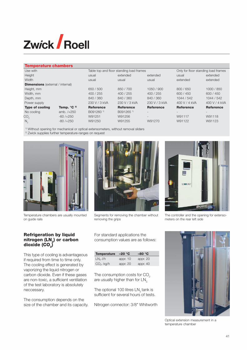
41
Refrigeration by liquidnitrogen (LN2) or carbondioxide (CO2)
This type of cooling is advantageousif required from time to time only.The cooling effect is generated byvaporizing the liquid nitrogen orcarbon dioxide. Even if these gasesare non-toxic, a sufficient ventilationof the test laboratory is absolutelyneccessary.
The consumption depends on thesize of the chamber and its capacity.
Segments for removing the chamber withoutremoving the grips
Temperature chambers are usually mountedon guide rails
The controller and the opening for extenso-meters on the rear left side
For standard applications theconsumption values are as follows:
Optical extension measurement in atemperature chamber
Temperature –20 °C –80 °C
LN2, l/h appr. 10 appr. 20
CO2, kg/h appr. 20 appr. 40
Temperature chambersUse with Table top and floor standing load frames Only for floor standing load framesHeight usual extended extended usual extendedWidth usual usual usual extended extendedDimensions (external / internal)Height, mm 650 / 500 850 / 700 1050 / 900 800 / 650 1000 / 850Width, mm 400 / 255 400 / 255 400 / 255 600 / 450 600 / 450Depth, mm 840 / 360 840 / 360 840 / 360 1044 / 542 1044 / 542
Power supply 230 V / 3 kVA 230 V / 3 kVA 230 V / 3 kVA 400 V / 4 kVA 400 V / 4 kVAType of cooling Temp. °C 2) Reference Reference Reference Reference ReferenceNo cooling amb. /+250 B091260 1) B091265 1) - - -
CO2 -60 /+250 W91251 W91256 - W91117 W91118N2 -80 /+250 W91250 W91255 W91270 W91122 W91123
1) Without opening for mechanical or optical extensometers, without removal sliders 2) Zwick supplies further temperature-ranges on request
The consumption costs for CO2
are usually higher than for LN2.
The optional 100 litres LN2 tank issufficient for several hours of tests.
Nitrogen connector: 3/8" Whitworth

42
Automatic SpecimenFeeding
Automatic specimen feeding systemsare mainly used for the efficient test-ing of very large series, especially inresearch centers where statisticallysafe results are needed.
Specimen feeding systems are avail-able in different task-specific designsfor plastic and rubber testing. (seetable below)
They are designed for executingdifferent test-types alternatively, i.e.tensile and flexural, as well astesting alternatively differentmaterials, i.e. thermoplastics andcellular materials.
Benefits of automatic testing
• user-independent test results• improved reproducibility
• more test capacity as the systemscan run “ghost-shifts” during thenight and weekends
• one-task handling systems are verysimple to operate by different users
• good/bad sorting of brokenspecimen
• magazine filling is possible whilethe system is running
• manually controlled tests are alsopossible
• simply adapted and expanded tospecific requirements
• short pay back time
“roboTest B”
This compact system allows testingof smaller batches in a fully auto-matic mode. In addition, the testingmachine can easily be operated inmanual mode if required.
This robotic testers can performflexural as well as tensile tests.
Specimen feeding systems
System roboTest A B F L L(Ring) P R I
N° of storage places, standard 5 to 20 5 to 20 100 to 200 150 to 450 50 / 300 100 to 400 up to 200 up to 25
Test Tensile • • • • • • • -Compression - - - - - • • -Flexural - • - • - • • -Tear - - • - - • • -Creep • • - • - • • -Charpy/Izod - - - - - - • •Multiaxial impact - - - - - - • -Hardness - - - • - - • -
Material Plastic film, sheetings - - • - - - - -Flexible materials - - • - - - • -Rigid and semi-rigid plastics • • • • - • • •Composites • • • • - • • •Foam - - - - - • • -Rings (Rubber) - - - - • - - -
Specimen dimensions, mmShoulder or strip width 6 to 25 6 to 25 10 to 50 6 to 25 - all all max. 10Thickness max. 15 max. 15 max. 5 max. 15 4 to 6 all max. 10 max. 10Over-all length max.260 max.260 max. 350 max. 260 - max. 350 max. 350 max. 55
OptionsThickness measurement - - - • • • • •Cross-section measurement - - - • - • • -Barcode identification • • • • - • • •Temperature chamber - - - - - - • •
The “roboTest B“ tester can switch fromtensile to flexural tests.
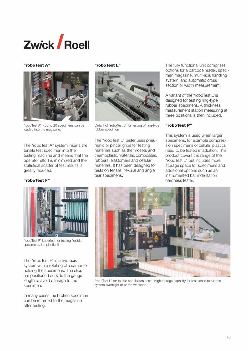
43
“roboTest F” is perfect for testing flexiblespecimens, i.e. plastic film.
Variant of “roboTest L” for testing of ring-typerubber specimen
“roboTest A”
The “roboTest F” is a two-axissystem with a rotating clip carrier forholding the specimens. The clipsare positioned outside the gaugelength to avoid damage to thespecimen.
In many cases the broken specimencan be returned to the magazineafter testing.
The “roboTest A” system inserts thetensile test specimen into thetesting machine and means that theoperator effort is minimized and thestatistical scatter of test results isgreatly reduced.
“roboTest F”
“roboTest A” - up to 20 specimens can beloaded into the magazine.
“roboTest L“ for tensile and flexural tests: High storage capacity for testpieces to run thesystem overnight or at the weekend.
“roboTest L” The fully functional unit comprisesoptions for a barcode reader, speci-men magazine, multi-axis handlingsystem, and automatic crosssection or width measurement.
A variant of the “roboTest L”isdesigned for testing ring-typerubber specimens. A thicknessmeasurement station measuring atthree positions is then included.
“roboTest P”
This system is used when largerspecimens, for example compres-sion specimens of cellular plasticsneed to be tested in addition. Thisproduct covers the range of the“roboTest L” but includes morestorage space for specimens andadditional options such as aninstrumented ball indentationhardness tester.
The “roboTest L” tester uses pneu-matic or pincer grips for testingmaterials such as thermosets andthermoplastic materials, composites,rubbers, elastomers and cellularmaterials. It has been designed fortests on tensile, flexural and angletear specimens.

44
“roboTest I”: Charpy impact testing with a large temperature range.
“roboTest R”: The illustrated system integrates tensile, flexural, and Izod testing.
“roboTest R”
This product is based on anindustrial robot with high flexibilityand positioning accuracy.
It is currently used for more complexprocesses such as testing in aboveor below ambient conditions using atemperature chamber.
The “roboTest R” can integrateseveral tests into one sequence. Forexample running tensile, flexural,hardness and impact tests inparallel within the same system.
“roboTest I”
For pendulum impact tests, pre-testing conditions such as specimentemperature as well as automatedfeeding of the specimen in to theimpact tester can easily be carriedout with the “robotest I”.
Tests according to the Charpymethod can be performed, anddepending of the type of cooling,temperatures down to -60°C oreven -180°C can be achieved.
Additional applications
Zwick supplies a vast range of roboticequipment for materials testing:• Izod and Charpy including
temperature devices• Hardness testers• Notching of Charpy and Izod
specimens• Component testing

45
Servo-hydraulic testing machineAmsler HC 5 for testing rubber mountings
ServohydraulicTesting Machines
Field of Application
Servohydraulic testing machines areused extensively for universaldynamic testing, and materialstesting applications requiring veryaccurate measurement and control.
Typical applications
• Dynamic analysis and characte-risation of rubber mountings,airsprings and elastomer dampers
• Characterisation of plastics,fibre reinforced and compositematerials
• Durability testing of syntheticmaterials and components
• Dynamic peel and separationtests on bonded materials andadhesive tapes
Unique Features
Zwick universal servohydraulictesting machines combine structuralrigidity with precise alignment toguarantee test data of the highestpossible integrity.
All load frames boast smooth hardchromium plated columns, frictionclamped by one-piece cross headsproducing a structural platform ofexceptional stiffness and rigidity withinfinite fatigue life at rated capacity.
The testing machines are equippedwith high performance fatigue ratedservo-hydraulic actuators, availablewith hydrostatic bearings or polymerbased plain bearings. Displacementtransducers are mounted concentri-cally inside the actuator body. Ma-chines are matched with hydraulicpower units and servovalves toensure application specific perfor-mance and efficiency.
Load Frames
• Type HAThe actuator is semi-integratedinto the lower crosshead. Hydrau-lic adjustment and clamping of theupper crosshead are available onall models.
• Type HBThe actuator is mounted in theupper crosshead. The HB designproves a flexible test space foroptimal specimen mountingpossibilities. Hydraulic adjustmentand clamping of the uppercrosshead are available on allmodels.
• Type HCThese tabletop test machinesare designed to be of a light-weight construction, with veryhigh frame stiffness. The actuatoris mounted in the upper cross-head resulting in a versatile frame,which can be tailored to customerrequirements. Hydraulic uppercrosshead adjustment is optional.The optional T-slotted table allowseasy mounting of components.
Measurement and control
Unrivalled performance is offeredusing the HydroWin 96xx controllerseries
• 10 kHz closed loop control anddata acquisition
• 19 bit A/D conversion with realtime linearisation
• Real-time derive channelsMIMICS advanced adaptivecontrol for non-linear testapplications
• Environmental control• Multi-channel control• Adaptive controller for non-linear
applications• 32 bit function generator
Servo-hydraulic testing machinesstandard designs1)
Model2) HC HB HA• Construction form table top floor standing floor standing• Nominal force, kN 5 – 25 50 – 1000 50 – 500• Testing stroke, mm 100 100 / 250 / 400 100 / 250• Specimen length, mm 100 – 700 100 – 1100 250 – 1500• Hydraulic power pack
* System pressure, bar 210 / 280 210 / 280 210 / 280* Throughput, l/min 5 – 23 8 – 270 8 – 270
• Max. power consumption, kVA 4.2 – 11 6.6 – 230 6.6 – 2301) Load frames can be supplied for higher forces, different dimensions and testing strokes2) Piston located below (HA) or above (HB, HC) the working area

46
High Speed TestingMachines
High-speed testing machines areused especially for high-rate punctureimpact and other materials testsrequiring high testing speeds.
Examples of applications:• Instrumented multiaxial impact
tests according to ISO 6603-2and ASTM D 3763
• Determination of tensile propertiesat high strain rates, ISO/DIS 18872
• Instrumented impact tests on semi-finished products and components
Characteristic features:• Design as two or four column
single test area load frame• Hydraulic or mechanical clamping
and adjustment of the uppercrosshead
• Built-in working cylinder
High-speed testing machine equipped formultiaxial impact tests
• Fixed lower crosshead to be usedas a clamping table
• Loading unit in shock absorbingconstruction to reduce vibration orshock transmission to the floor
• Double operation cylinder fortensile of compression loading
• Piston without sealing rings• Double-sided hydraulic end-
position damping of the piston• Optional kit for transforming the
high-speed testing machine into aservo hydraulic-dynamic testingmachine for cyclic or monotonicquasi-static tests.
testXpert® shows all relevant data of an instrumented puncture impact test
High-Speed Testing Machines Standard models*
Model Amsler HTM2512 2520 5012 5020
• Rated force, kN 25 25 50 50• Speed, m/s 12 20 12 20
* Other sizes and speeds available upon request.
Testing in hot and coldconditions
High speed testing machines canbe used in a large temperaturerange. (see chapter Temperaturechambers)

47
Falling weight testers
Falling weight testers are used todetermine the dynamic behavior ofmaterials within a limited speedrange from about 3 m/s. Thefollowing tests can be performedwith the instrumented Falling weighttester HIT230F:
• Multiaxial impact tests accordingto ISO 6603-2, ISO 7765-2, andASTM D 3763 at ambient andnon-ambient conditions.
The drop height of 1 m allowsimpact speeds of up to 4.43 m/s.
Instrumented multiaxialimpact test
The plate-type specimens to be testedare held with a pneumatic clampingdevice and then impacted by aninstrumented tup of standardizeddiameter with hemispherical tup insert.
Depending on the standard, differenttups and clamping rings are available.During the test the load-time signalis measured. The force-travel signalas well as the energy consumedduring impact can be calculatedfrom this data by the software. Thepotential energy of the falling weighttester must be at least 2.78 timeslarger than the consumed energy toensure that the speed-drop duringimpact remains less than 20% asrequired by most standards.
Test specimen can be cooled in a coolingbox and then tested within 4 to 5 secondsdue to the good accessibility.
High resolution and natural frequencyprovide outstanding force signal quality.
The instrumented Falling weight tester HIT230 F is fast and simple to operate.
Technical Data:
Maximum Energy 230 JDrop height: 0.1 to 1 mFalling weight 23 kg
Load signalresolution 16bit
Elect. connection 85 to 132 VAC170 to 264 VAC
Power 500 W
Specimens are pneumatically clamped for themultiaxial impact tests.

48
Pendulum Impact Testers
HIT pendulum impact testers arepowerful instruments, designed tomeet the exact specifications ofinternational standards in everyrespect. These instruments are theultimate in reliability for bothresearch and quality control.
ISO 13802 compliantThe base of the tester is made ofvibration damping cast iron. It is fullycompliant to the Standardsregarding the frame-pendulum massratio. Three heavy duty levelling feetensure solid installation as well aslevelling capability.
Pendulum RecognitionEach installed pendulum is automati-cally recognized by the electronicsto ensure that the correct pendulumis used for each test.
Ergonomic designAll important operating elementssuch as keyboard, brake, releaselever and display are all within easyreach of the operator.
Pendulum changewithout toolsEach pendulum is equipped with aquick change unit. Changing ofpendulums can be carried outquickly without special tools.
Changing test methodThe vices for the different methodsare securely guided and clampedwith dovetail grooves. Whilstenabling the tester to be quickly
setup for each type of test, it alsoguarantees a perfect connectionbetween the support and the frameof the impact tester.
Universal Pendulum Impact Tester HIT 50 P with CE-conforming safety housing and motorizedpendulum lift.
The universal Pendulum Impact Tester HIT5.5P can perform Charpy, Izod, Tensile Impact andDynstat impact tests according to ISO, ASTM and DIN standards.
Pendulum Impact Tester HIT5P for testingaccording to ISO standards.

49
Charpy test
Izod test
Tensile-impact test ISO method A
Dynstat test
Standard requirements
Char
py
Tensi
le im
pact
Tensi
le im
pact
–„t
ensi
le-i
n-h
ead
“ m
eth
od
Dyn
stat
Izod a
nd „
Unnotc
hed
can
tile
ver
beam
im
pact“
ISO
179
AS
TM D
611
0IS
O 1
80A
STM
D 2
56 /
D 4
812
ISO
825
6 –
met
hod
AIS
O 8
256
–m
etho
d B
AS
TM D
182
2D
IN 5
3435
0.5 0.37 • • • • • • • •1 0.74 • • • • • • • •2 1.48 2.9 m/s • • • • • • • •4 2.95 (±10%) • • • • • • • •5 3.69 • • • • • • • •
7.5 5.53 - - - - • • • •15 11.1 3.8 m/s - - - - • • • •25 18.4 (±10%) - - - - • • • •50 36.9 - - - - - - • •0.5 0.37 approx. - - • • • • • •1 0.74 3.46 m/s - - • • • • • •
2.7 2 - - • • • • • •5.4 4 - - • • • • • •
10.8 8 (Height of fall: - - - - • • • •21.6 16 610±2 mm) - - - - • • • •1.0 0.74 - - • • • • • •
2.75 2.03 3.5 m/s - - • • • • • •5.5 4.06 (±10%) - - • • • • • •11 8.11 - - - - • • • •22 16.2 - - - - • • • •1.0 0.74 approx. - - • • • • • •
2.75 2.03 3.46 m/s - - • • • • • •5.5 4.06 - - • • • • • •11 8.11 (Height of fall: - - - - • • • •22 16.2 610±2 mm) - - - - • • • •2,0 1.48 2.9 m/s • • • • • • • •4.0 2.95 (±10%) • • • • • • • •7.5 5.53 - - - - • • • •
15.0 11.1 3.8 m/s - - - - • • • •25.0 18.4 (±10%) - - - - • • • •50.0 36.9 - - - - - - • •2.0 1.48 2.9 m/s - - • • • • • •4.0 2.95 (±10%) - - • • • • • •7.5 5.53 - - - - • • • •
15.0 11.1 3.8 m/s - - - - • • • •25.0 18.4 (±10%) - - - - • • • •50.0 36.9 - - - - - - • •2.7 2 approx. - - • • • • • •5.4 4 3.46 m/s - - • • • • • •
10.8 8 (Height of fall: - - - - • • • •21.6 16 610±2 mm) - - - - • • • •0.2 0.15 - - - - - - - -0.5 0.37 2.2±0.1 m/s - - • • • • • •1.0 0.74 - - • • • • • •2.0 1.48 - - • • • • • •4.0 2.96 - - • • • • • •
J ft lbf m/s
HIT 5 P HIT 5.5 P HIT 25 P HIT 50 P
Meth
od
Sta
ndar
d
Sta
nd A
lone
PC
Sta
nd A
lone
PC
Sta
nd A
lone
PC
Sta
nd A
lone
PC
Pendulu
menerg
y
Velo
cit
y at
impac
t

50
The HIT5.5P Pendulum Impact Tester has beenaccredited for “authoritative” tests by theGerman Materials Testing Institute MPA-NRW.
Instrumentation allows the acquisition of the force-time and travel information.
The twin carbon rod pendulum minimizesenergy losses.
Specimen dispenser and magazine for lowtemperature testing.
Conventional pendulum
Carbon twin-rod pendulum
Virtually vibration freeA new innovation features twin carbonrods of carbon for the pendulum. Thisprovides high stiffness in the direction ofimpact and concentrates the pendulummass at the impact point. Compared totraditional single-rod, metal pendulumsand compound-type pendulums, theenergy loss due to resonant oscillationsat impact is considerably reduced.
Precise specimen supportsThe specimen supports are precision-ground components ensuring thatevery radius and relief grooveconforms exactly to the standards.
Accreditation for“authoritative” testsA HIT Pendulum Impact tester hasbeen verified as an example in alldetails by the German MPA-NRW inorder to prove its ability to obtainthe accreditation for authoritativetests. In Germany this is the highestlevel that any instrument can obtain.
Powerful PC-SoftwaretestXpert® II (Option)By connecting the PendulumImpact Tester to a PC via a USBinterface, and using testXpert® IIsoftware, the highest level ofcomfortable operation, reporting,and data administration becomepossible. A separate RS232interface is available to connectdirectly to existing LIMS systems.
Low-wear disc brake (Option)The optional disc brake allows thependulum to be stopped smoothly.
Instrumentation (Option)For determination of the force-displacement-time behavior, loadsensors and a high-speed measure-ment system are used. This allowscomfortable yet detailed fracturemechanics analysis in the R&Denvironment, or routine and auto-matic recognition of brittle-ductiletransitions when using the systemfor quality assurance.
Testing at low temperatures(Option)The easiest way to perform tests atlow temperatures is by cooling thespecimen in a normal cooling box.
To reduce temperature variationsduring a test sequence, speciallydesigned and insulated specimenmagazines allow a series of speci-mens to be brought close to theimpact tester. This magazine is thenplaced on a specimen dispenser thatallows to the operator to take thespecimens out one-by-one and toplace them into, or on, the supportsfor testing. Testing can be carriedout within approx. 3 seconds afterremoving them from the magazine.
An optional digital thermometer isavailable to monitor the temperaturewithin the magazine.
For testing very high specimenthroughput, we recommend ourrange of roboTest solutions.

51
Material kJ/m2
ABS 14 - 35EP 2.2 - 2.7MF 1.3 - 2MPF 1.3 - 3PA66 5.5 - 75PA66-GF50 17 - 21PA6 7 - 110PA6-GF50 13 - 23PBT 6 - 27PC 5 - 90PE-GF 18 - 27PET 2 - 13PET-GF 4 - 14PMMA 2 - 5.5PP 3 - 40PP-GF 12 - 21PS 3 - 9PTFE 80
Pendulum size:
1. Izod notched, Specimen 3.17 x 12.7 mm (1/8 x 1/2 in) – ASTM D 256
1.0 Joule2.7 Joule
5.4 Joule10.8 Joule
21.6 Joule
ASTM permittedASTM recommended
Used signs:
0.05 0.1 0.2 0.5 1.0 2.0 5.0 10.0 20 50 Joule
0.0037 0.074 0.15 0.37 0.74 1.48 3.70 7.4 14.8 37 ft lbf
1.55 3.1 6.2 15.5 31 62 155 310 621 1552 kJ/m2
0.296 0.59 1.20 3.0 5.9 11.8 29.6 59 118 296 ft lbf / in
Specimen:
Material kJ/m2
ABS 20 - 80EP 4 - 9MF 7 - 9MPF 7 - 9PA66 150PA66-GF20 50 - 95PA6-GF 90 - 100PBT 25 - 300PC 70 - 310PE not specifiedPET 25 - 70PET-GF 30 - 60PMMA 16 - 80POM 150 - 320PP 50 - 120PS 8 - 160
Pendulum size:
2. Charpy unnotched, Specimen 4 x 10 mm, (1eU), ISO 179-1
2 Joule4 Joule
5 Joule7.5 Joule
15 Joule
0.5 Joule1 Joule
0.05 0.1 0.2 0.5 1.0 2.0 5.0 10.0 20 50 Joule
1.25 2.5 5 12.5 25 50 125 250 500 1250 kJ/m2
ISO permittedISO recommended
Used signs:
25 Joule50 Joule
Specimen:
Indicated values for Izod impact resilience according to ASTM standard are only valid for specimen cross-sections 1/8“ x 1/2“ (3.17 x 12.7 mm).
Indicated values for Charpy impact resilience are only valid for unnotched specimen, 10 x 4 mm.

52
Extrusion plastometers
Melt flow plastometers deliver stan-dard values of melt mass-flow rate(MFR) and melt volume-flow rate(MVR) of thermoplastic materialsunder specified conditions of tem-perature and load.
The standards ISO 1133 andASTM D 1238 describe these testsfor many different materials, whilstASTM D 3364 defines a specificmethod for testing PVC.
The new draft standard ISO/CD 1133-2prepares the description of a methodfor time-history dependent andmoisture sensitive materials, suchas PA, PET and PBT that requiresspecific pre-conditioning of thesamples and higher technicaldemands on the plastometers.
Method A:Cutting of extrudates with constanttime intervals, followed by weighingwith an analytical scale. The result isthe MFR value presented in g/10min.
Method B:Measurement of piston travel andtime during the test. The result is thevolume extruded through the stan-dard die per unit of time, presentedas the MVR value in cm³/10 min.
Method C (according to ASTM):Measurements with a “half-size die”.The method is used for polyolefinsshowing high flow rates. Theprocedure is identical to method B.
Method D (according to ASTM):Measurement as for method B, butunder different loads within onebarrel filling. A specific automaticload-change unit is needed, see4106.200.
MFR and MVR values can be con-verted using a known melt density.
Modular Plastometer Mflow
In the basic version, this plastometeris equipped for MFR measurementsaccording to method A. By addingoptions such as a piston traveltransducer, the instrument is able tomeasure MVR as well. It then uses theunique “Adaptive Parameter Control(APC)” function which enables autoprogramming of the test procedurefor all flow rates. This relieves theoperator from estimating the flow ratein order to find the best fitting para-meters. The plastometer can auto-matically find the best fitting parametersand apply them to each test.
Advantages:• Very high temperature accuracy• Adaptive Parameter Control (APC)• Modular and extendable design• Stand-alone operation capabilities• Comfortable PC control using
testXpert® II software• Automatic air bubble recognition
and exclusion• Large range of accessories
Precise temperature control developed forthe testing of PA, PBT and PET.
Modular plastometer Mflow for comfortable MFR and MVR measurements. Here shown withoptional separation shield, piston travel transducer, automatic weight release system and PCsoftware control.
From the first test “Adaptive ParameterControl”, (APC) enables each test to beperformed with optimum parameters in realtime.

53
Zwick 4106 – the melt flowplastometer complying withmethods A, B, C and D
The plastometer 4106 covers thecomplete application range definedthroughout the standards.
The instrument is equipped with anautomatic weight change unit,specifically developed for QA/QC. Inmulti-stage tests, the weights canbe freely changed from high to lowor vice versa. Measuring time andtravel can be individuallyprogrammed for each load step.
Advantages:• Automatic weight release• Automatic weight change• Integrated piston travel transducer• High temperature accuracy• Stand-alone operation capability• Comfortable PC control by using
testXpert® software• Good accessibility for cleaning• Automatic results calculation• Pre-programmable switch-on time.
Compact Plastometer,Cflow
The Cflow plastometers areexclusively designed for MFRdetermination according to methodA. The instrument is equipped witha precise temperature control,simplified purging function via thedie release system, manual ormotorized filament cutting option,and an optional nozzle plug fortesting very fluid melts.
All standardized weights up to 21.6kg are available fort he Cflow model.For frequent tests with weightslarger than 5 kg we recommend theuse of the Mflow model includingthe automatic weight lift option.
Extrusion plastometer Zwick 4106.200 with automatic weight change unit. Upper right: thebasic version with manual weights.
Cflow: Simple to use plastometer for thedetermination of the MFR value (Analyticalbalance required)
Die release system
Filament cutter with nozzle plug

54
Heat distortion tempera-ture under load and Vicatsoftening temperature,HDT and VST
Heat Deflection Temperature(HDT)of thermoplastics, hard rubber, fibrereinforced and filled hardeningplastics, according to ISO 75 parts1 to 3 and ASTM D 648 Method B
Vicat Softening Temperature(VST)of thermoplastics, according toISO 306 and ASTM D 1525
Creep test characteristicsunder flexural loading
HDT/Vicat Standard series
HDT/Vicat Standard instrumentshave been designed especially forincoming goods inspection, qualityassurance, and for education andtraining purposes. Versions with upto 6 measurement stations areavailable. Programming of the testsequences and setup of test resultspresentation are comfortablyperformed when using a connectedPC and testXpert® II (Option).
Functions, elements andinterfaces
• Test temperatures up to 250°C or300°C according to model
• Built-in microprocessor-controllerfor temperature control
• Easy-to-read display• Safety thermostat• Electronic bath level monitoring
with instruments up to 300 °C• Test control and data acquisition
via PC with testXpert® II (2RS232-Interfaces required in PC)
• Integrated compensation in PCmode for the thermal expansion ofthe measurement stations
• Manual immersion of the testingstations
• Manual placing of test weights
• Manual or solenoid valve controlledwater-cooling according to model.
• Connection for external chillers
PC-controlled test sequence
As soon as the heat transfer liquidhas reached the startingtemperature, the specimens areplaced in the measurement stationsand are manually lowered into thebath. The next step is to manuallyposition the weights as indicated inthe standard and to start the testsequence on the PC.
The travel transducers are zeroedafter an indicated creep time underload. Then the heating is startedwith a preset and controlled heatingrate.
As soon as the test is over, theheating will be switched off. Coolingof the heat transfer liquid will thenbe automatically switched on by thePC-software or manually by theoperator.
Upper: Vicat softening temperature, VST,Lower: HDT, heat deflection temperature.
Standard model HDT/Vicat 3-250 S: Measurements up to 250°C, 1to 3 measurement stations, with PC connection.
The instrument HDT/Vicat 6-300 S is equipped with a solenoid valve forenhanced control of cooling. It can be equipped with 1 to 6measurement stations.

55
HDT/Vicat Allround
The Allround series instruments areequipped with a motor driven lift forthe measurement stations. Thispermits the stations to be immersedinto the liquid using an automaticsequence and to lift them againafter the liquid has been cooledback to ambient temperature.
Furthermore, all instruments areequipped with an automatically con-trolled cooling unit. Depending on themodel this can be a simple coolinghose or an oil-water heat exchangerfor fast and powerful cooling.
Functions, elements andinterfaces
• Integrated PLC controller for tem-perature control and data acquisition
• Cooling sequence controlled bysolenoid-valve
• Motor driven immersion of themeasurement stations.
• Manual placement of weights• Safety thermostat• Electronic bath level monitoring• Test control and data acquisition
via PC with testXpert® II• Integrated compensation for the
thermal expansion of themeasurement stations
Vicat-Dry
ISO 306 (Vicat Softening Tempera-ture) describes the contact heat
transfer method that is used by thisinstrument. Round robin tests haveshown that, for several materials,the results obtained are statisticallyidentical to results obtained with theliquid heat transfer method workingwith an oil bath.
No more annoying oil fumes!Vicat-Dry instruments are very com-fortable to operate. They are oftenused in R&D environments, but alsoin incoming goods inspection andquality control. The oil-free measure-ment principle ensures clean opera-tion without odours. The whole testsequence runs in automatic mode.All parameters can comfortably beset in testXpert® II.
Specimen dimensions max:10 by 6.5 by 10 mm
The Vicat 6-300 D works according to the contact heat transfermethod without oil. The test is performed in a metal heating blockequipped with 6 measurement stations.
The HDT/Vicat 6-300 A is equipped with up to 6 stations. The wholetest sequence can run in PC-controlled automatic mode.
Technical data Vicat-Standard Vicat-Allround Vicat-Dry
Accuracy at 250 °C ± 0.5 °C ± 0.5 °C ± 0.5 °CSpatial distribution ± 0.1 °C ± 0.2 °C ± 0.2 °CResolution 0.1 °C 0.1 °C 0.1 °CHeating rates 50 to120 K/h (all)Accuracy, displacement ± 0.01 mm ± 0.01 mm ± 0.01 mmVoltage 230 to 240 V 230 V 230 VFrequency 50 to 60 Hz 50 Hz 50 HzPower 2000 W 3000 W 3000 W
The HDT/Vicat 3-300 A is equipped with anintegrated water-oil heat exchanger for fastcooling of the heat transfer liquid.
The Allround model HDT/Vicat 6-300 A is fittedwith a motorised station lift that allows thewhole test to be run automatically.

56
Rebound resilience tester Zwick 5109 with digital display
Pendulums for different types of tests
Rebound Resilience Tes-ter Zwick 5109
The device also known as “SchobPendulum” is perfectly suitable forinvestigating the rebound resilienceon rubber, elastomers and flexiblecellular materials in accordance tothe following standards:
• ISO 4662, DIN 53512,ASTM D 1054 method B:Rebound resilience of rubber andelastomers
• DIN 13014, DIN 53573: Reboundresilience of flexible cellularmaterials
Specimen shapes
Rubber and elastomers are tested inform of circular or square platesfrom 28 to 50 mm. The specimenthickness should not exceed15 mm. Flexible cellular materialsare tested by taking squarespecimens 80 x 80 mm with athickness of 50 mm.
Technical DataOrder no.: Zwick 5109Pendulum length: 200.4 mmRelease angle: 90°Impact velocity: 1.98 m/sElectr. connection: 100...240 V
50...60 Hz
Pendulum acc. to ISO 4662,ASTM D 1054 and DIN 53512Impact energy: 0.5 JPendulum mass: 252 gShape of impact fin: hemisphereDiameter: 15 mmApplication: rubber,
elastomers
Pendulum acc. to DIN 13014Impact energy 0.196 JPendulum mass 101gShape of impact fin: hemisphereDiameter: 30 mmApplication: mattresses
OptionsElectrically heatable specimenfixtures (Ambient to 100 ºC)

57
Abrasion tester Zwick 6103
Abrasion tester
The abrasion tester conforms withthe standard ISO 4649. It is used toevaluate the resistance of rubbersand elastomers to frictional wear.
The method compares the wear ofan unknown test piece to that of aknown material.
A sheet of abrasive paper is at-tached on the drum. The specimenis placed into a specimen holder,which enables the sample to movelaterally and to rotate during thetest. The necessary load is appliedby a dead weight to the test-piece.The result is given by weighing thetest piece before and after the test.
Technical dataSample diameter: 16 mmSample height: 6 ... 16 mmLoading forces: 2.5/5/7.5/10 N/
12.5/15NLateral movement: 4.2mm/revolut.Sample rotation: 0.9 rpmAbrasion path: 40 mAbrasion speed: 19.2 m/minDrum diameter: 150 mmDrum length: 460 mm
Accessories and options• Abrasive sheet• Sheet of rubber comparison
sample (for approx. 100 samples)• Circular cutting tool for use with a
drilling machine• Additional weights for loading
forces 12.5 / 15 / 17.5 and 20 N• Drum cleaning unit• Precision balance (see chapter:
dimension measurement)
Ball-type reboundresilience tester
This microcomputer controlled instru-ment is designed for the determi-nation of the rebound resilience ofsoft foam materials according to ISO8307 and ASTM D 3574.
A steel ball with a diameter of 16 mmis precisely released by a magnetand drops from a height of 500 mmon the surface of the test-piece. Bymeans of a triple beam light barrierthe rebound height of the ball isthen measured.
Technical data:Drop height 500 mmBall release by magnetTube, inside diam. 40 mmMeasurement light barrierStatistics Median and
single valuesPC connection RS 232Electrical connect. 115V/60 Hz and
230V/50…60 Hz
Ball-type rebound resilience tester for softfoam materials

58
Hardness testers andhardness testingmachines
In general, hardness is defined asthe resistance of a material againstthe penetration of a specifiedindentor. Since hardness is notdirectly measurable, it is determinedfrom other measurement variablessuch as penetration depth orpenetration force. The determinationof reproducible and comparablemeasurement values requiresdefined conditions, e.g. the shapeand dimensions of the indentor andthe force acting on it. The differentconditions and requirements forpractical application resulted indifferent hardness test methods.
Analog Shore A hardness tester with controlunit
Test stand for Shoredurometers
The manual hardness testers can bemounted into a test stand(additional device) to improve therepeatability of the test method byeliminating operator influences.
Attachable prisms formeasurements on printingrollers
An attachable prism facilitates themeasurement on drums andprinting rollers.
Application ranges
Method HardnessBarcol, EN 59 0 - 100ASTM D 2583Shore A 10 - 90ISO 868IRHD smooth 10 -40ISO 48IRHD normal 40 -98ISO 48Shore D 30 - 90ISO 868Ball indentation hardness 8,6 - 467ISO 2039
Analog Shore A hardness tester with teststand
Analog Shore A and D hardness tester:Hand-held devices
Digital Shore hardness tester with integratedelectronic unit, installed in a test stand
Shore A and Shore Ddurometers
These hardness testers, using aspring-loaded indentor of twodifferent shapes according to thedefinition of Shore A and Shore D,are available with analog display,optionally also with drag pointerindicating the maximum hardnessvalue, as well as digital display andmicroprocessor for the data storage,statistical evaluation, printout anddata transfer to a PC.
Shore A hardness testers are usedfor non-rigid to semi-rigid plasticsand for rubbers and elastomers of aminimum thickness of 6 mm.Plastics showing greater hardnessvalues shall be tested with theShore D hardness tester or otherconvenient methods.
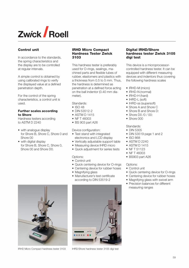
59
Control unit
In accordance to the standards,the spring characteristics andthe display are to be controlledat regular intervals.
A simple control is obtained byusing calibrated rings to verifythe displayed value at a definedpenetration depth.
For the control of the springcharacteristics, a control unit isused.
Further scales accordingto ShoreHardness testers accordingto ASTM D 2240
• with analogue displayfor Shore B, Shore C, Shore 0 andShore 00
• with digital displayfor Shore B, Shore C, Shore 0,Shore 00 and Shore D0.
Digital IRHD/Shorehardness tester Zwick 3105digi test
This device is a microprocessor-controlled hardness tester. It can beequipped with different measuringdevices and indentors thus coveringthe following hardness scales
• IRHD-M (micro)• IRHD-N (normal)• IRHD-H (hard)• IHRD-L (soft)• IHRD-ss (supersoft)• Shore A and Shore C• Shore B and Shore D:• Shore D0 /0 / 00:• Shore 000
Standards:• DIN 5305• DIN 53519 page 1 and 2• ISO 868• ASTM D 2240• ASTM D 1415• NF T 51123• NF T 46003• BS903 part A26
Options:• Control unit• Quick centering device for O-rings• Centering device for rubber hoses• Magnifying glass with swivel arm• Precision balances for different
measuring ranges
IRHD Micro CompactHardness Tester Zwick3103
This hardness tester is preferablyused for O-rings, sealings, ma-chined parts and flexible tubes ofrubber, elastomers and plastics witha thickness from 0.5 to 5 mm. Thus,the hardness is determined aspenetration at a defined force actingon the ball indentor (0.40 mm dia-meter).
Standards:• ISO 48• DIN 53512-2• ASTM D 1415• NF T 46003• BS 903 part A26
Device configuration:• Test stand with integrated
electronics and LCD display• Vertically adjustable support table• Measuring device IHRD micro• Quick adjustment for series tests
Options:• Control unit• Quick centering device for O-rings• Centering device for rubber hoses• Magnifying glass• Manufacturer’s test certificate
according to DIN 53519-2
IRHD Micro Compact hardness tester 3103 IHRD/Shore hardness tester 3105 digi test

60
Hardness tester 3108 acc.to Pusey & Jones
With this device standardizedaccording to ASTM D 531, thepenetration depth of rubber andsimilar materials (e.g. rubber rollers,standardized blocks) withthicknesses from 13 mm aremeasured.
Indentor: Ball, diameter 3.175 mmLoading weight: 1,000 ± 1 gReading unit penetration depth:0.001 mm
Hardness tester 3108 acc. to Pusey & Jones
Ball indentationHardness tester Zwick3106
This method according to ISO 2039-1is used for the testing of rigidplastics and ebonite. The range ofapplication starts at approximately60 Shore D. The ball indentationhardness may provide values forresearch, development, qualitycontrol and acceptance or rejectionaccording to specification.
With this method, a ball with adiameter of 5 ± 0.02 mm is forcedunder a specific test load into thesurface of a specimen. Thepenetration depth is measuredunder load and is related by anequation to the measured hardnessin N/mm2 .
Technical data:Order no.: Zwick 3106Load application: WeightsLoads: 49 / 132 / 358 /
961 / 1471 NPre-loads: 9.8 to 98 NStandard ball: 5 mmFurther balls: 1.58 ...12.7 mmPenetration depthmeasurement: digitalResolution: 0.001 mmAnvil diameter: 25 mm
Further standards using the ballindentation hardness tester:• ASTM D 785: Rockwell hardness
(plastics)• ISO 6508: Rockwell hardness
(metals)• DIN 1168-2: Hardness of plaster• DIN 1996: Indentation test
method for asphalt• DIN 51917: Rockwell hardness
of carbon materials• EN 433: Residual indentation
(floor coverings)
Barcol hardness testerZwick 3350
The Barcol method is described inthe standards EN 59 and ASTM D2583. It is used for the testing ofharder plastics (e.g. glass fibrereinforced plastics, thermosettingmaterials, hard thermoplastics).
Indentor: Truncated cone with acone angle of 26º and a truncatedcone surface diameter of 0.157 mm.Test travel max. 0.76 mm.The device is supplied with anelectronic unit for the display andstorage of the test data. A teststand is optionally available.
Ball indentation hardness tester 3106
BARCOL hardness tester
Rockwell hardness tester for scales R, L, M,E, K and α

61
Zwick Services
Worldwide Service
Customer satisfaction is a top priorityof the Zwick Roell Corporation.With local service organizations inover 50 countries, we help optimizethe return on your investment andto ensure the functionality of yourtesting machine.
Engineering Consulting Services
Changing specifications, new testrequirements, or the installation ormodification of a test lab can beoptimized by consulting experts.Experienced Zwick engineers canadvise you in the planning and imple-mentation of such complex projectsto meet your exacting requirements.
Demonstration
The decision to purchase a materialstesting system and accessories de-pends on a number of factors. Inorder to help facilitate this decision,Zwick maintains a fully-equippedApplications Lab to perform trialtests to ensure the selection of theappropriate equipment and acces-sories.
Pre-Testing
In the course of new, modified, or verycomplex applications, it is necessaryto perform specific tests prior topurchasing or expanding a testsystem. Zwick’s Application Lab isavailable in conjunction with its nu-merous ex-perts and extensive selec-tion of machines and fixtures in orderto initially verify the testing set-up.
Contract Testing
Whether for new test requirementsor tests performed to particulartechnical specifications, the ZwickContract Lab provides timely andaccurate test results on a contractbasis. Please contact us forspecific contract testing capabilitiesand pricing.
Application TechnologySeminars
Active collaboration with partnersfrom research and technologyqualifies us to impart knowledge inprinciples of materials testing andexpertise within Application Techno-logy Seminars.
Preliminary acceptance
Prior to delivery of your machine, youhave the opportunity to conduct apreliminary acceptance checkout atour facility. This will allow you be-come acquainted with the operationof the machine and confirm theagreed-upon functionality.
Transport
Everything is available from a singlesource with ZwickService. Uponrequest, and where applicable,within the scope of initial operation,ZwickService will monitor the com-plete transport. Beyond that, it isalso possible to have the machinetransported all the way to the instal-lation site. Convenient and profes-sional. You no longer need to beconcerned about the transport atyour facility.
Retrofit
Converting the old into new –ZwickService specialists professio-nally perform the upgrade of yourexisting materials testing machine,regardless of the original manufac-turer. This allows the latest digitalcontrol technology and softwareautomation to enhance the perfor-mance of your testing system at thefraction of the cost of a new system.

62
Installation Machine Relocation
ZwickService provides for the com-plete relocation of your testing ma-chine as needed. Our experiencedmanagement team takes responsibi-lity for the detailed planning, from thedisassembly and transport, throughto re-installation of the machine. Themachine will be ready for testing atits new location on schedule. Inde-pendent of the manufacturer of yourtesting machine – ZwickService hasspecially trained and experiencedstaff for every make or model.
Software Adaptation
Our software engineers have the solidtechnical expertise from years of ex-perience to quickly deliver program-ming tailored to your individual needs.The testing requirements are definedin close cooperation and agreementwith you and subse-quently carriedout according to these specific needs.
Product Training
Customer Support
ZwickService ensures the optimalinstallation of your testing machineand accessories based on the ex-perience from several thousand in-stallations. Functional tests performedprior to final acceptance guaranteea successful installation process.
Hardware Overview
Nothing is left to chance duringZwickService test machine commis-sioning. The on-site commissioningis performed systematically andprofessionally on a checklist basis,and ensures an optimal utilization ofthe test hardware.
Software Overview
The introduction is performedfollowing a checklist procedure,using a specific example from theoperator’s daily practice. The resultswill be saved for later use.Alternatively, ZwickService offers atwo-stage introduction whichincludes an initial basic overviewand a final review at a later date.
Zwick maintains a staff of qualified,expert trainers, who have extensivepractical experience and who con-duct product training courses eitherat Zwick, or specially customized tobe performed at the customer’sfacility.
The trouble-free performance of yourtesting machine is of importance tous. Should any unforeseen malfunc-tion occur with the machine’s hard-ware or software, our competentexperts at our Hotline will be happyto assist you. If you are not able tospeak to someone immediately, wepromise to return your call as soonas possible.
Support Desk
Our Support Desk is a cost-savingalternative to on-site visits or trainingby a service technician. We assistyou in questions regarding theoperation of hardware and software,adaptation of your test programs oroffer further technical support. Theextensive application experienceenables our service technicians toprovide quick and effective solutionsto any questions you might have.

63
Rentals
Whether for temporary testing re-quirements or to satisfy a short-term need, ZwickService providesthe rental of testing grips. Pleasecontact us for further informationabout the rental service.
Maintenance
Upon request, ZwickService per-forms the regularly-required mainte-nance of machine and accessoriesas des-cribed in the instructionmanual and monitors the main-tenance intervals.
Inspection
ZwickService helps reduce down-time significantly by regularly in-specting your test system. Theinspection plan documents the con-dition of the machine, allows imme-diate exchange of worn parts asneeded, and the recommendationof preventive measures.
Repair Work
Should a failure in your materialstesting machine occur in spite ofthorough inspection and mainte-nance, one of the many techniciansof the ZwickService network is avai-lable on short notice. Spare parts,from Zwick’s large inventory, will bedispatched within short term.
Calibration
ZwickService calibrates your testingmachine and testing systems com-pliant to the current national and in-ternational standards, including ISOand ASTM. Zwick has associatedcalibration laboratories in differentcountries, all of them accredited inaccordance with ISO/IEC 17025.Consequently we are authorized foron-site calibration of testing machinesand testing systems according tothe relevant standards (DKD, UKAS,COFRAC, A2LA) and to issue thecorresponding calibration certifi-cates which are internationallyaccepted.
Software Upgrade
Upgrade your testXpert® software tothe latest version. This allows you totake advantage of the most recentdevelopments and the enhancedfunctionality of testXpert®. The latestchanges of relevant materials testingstandards are also incorporated inthe newest testXpert® version.
When upgrading your outdatedDOS software to the latest Windowstech-nology you can take advantageof improved performance andbenefits. With an upgrade fromtestXpert® to testXpert® II you benefitfrom the latest significant develop-ments in application software.
With an update or an upgrade of testXpert®
Zwick customers are able to take advantageof the latest technology and developments.
1) DKD: Deutscher Kalibrier-Dienst2) UKAS: United Kingdom Accreditation
Service3) COFRAC: Comité Français d´Accréditation4) A2LA: American Association for
Laboratory Accredition

64
Subject Standard Testing device Page
Testing equipment: design, verification, accuracy, environmental conditions
• Tensile, compression and bending machines ISO 5893, ISO 7500-1, ASTM E 4, ISO 9513, DIN 51220
• Impact testing machines ISO 13802, JIS B7756, EN 10045-2, DIN 51230
• Standard atmospheres for testing ISO 291, JIS K 7100, ASTM D 618
• Conditioning and test conditions for rubber ISO 471, DIN 53500, ASTM D 1349, ASTM D 832
• Performing of round robin tests ASTM E 691
• Temperature devices for rubber testing ISO 3383
Sample preparation
• Injection moulding ISO 294-1/-2/-3/-4 Injection moulding machine -
• Compression moulding ISO 293, ISO 295 Moulding press -
• Machining ISO 2818 Cutting press, strip cutter 11
• Rubbers ISO 4661-1, ASTM D 1485, ASTM D 3183 Cutting press 11
• Multipurpose test specimen for plastics ISO 3167, JIS K 7139 11
• Test specimen for plastics ISO 20753 -
• Test specimen for PS ISO 1622-2 -
Dimension measurement
• Multipurpose specimen ISO 527-1, ISO 16012, ASTM D 5947 Micrometer 16
• Thickness of plastic film ISO 4593, DIN 53370, ASTM D 374, ISO 4591, Dead weight thickness gauge, 16/18
ASTM E 252 balance
• Rubbers ISO 37, ISO 4648, DIN 53504, DIN 53534, Dead weight thickness gauge, 16/18
ISO 3302, ASTM D 3767, balance
• Cellular plastics and rubbers ISO 1923, DIN 53570 Dead weight thickness gauge, 16vernier calipper
Thermoplastic and thermosetting plastics
• Tensile properties ISO 527-1/-2, ASTM D 638, ASTM D 1708, Material testing machine 18
EN 2747
• Poissons ratio ISO 527, ASTM E 132 Material testing machine
• Flexural properties (1 point method) ASTM D 747 Material testing machine 18
• Flexural properties (3 point method) ISO 178, ASTM D 790, ASTM D 5934 Material testing machine 18
• Flexural properties (4 point method) ASTM D 6272 Material testing machine 18
• Compression properties ISO 604, ASTM D 695 Material testing machine 18
• Shear properties ASTM D 732 Material testing machine 18
• Creep behaviour, tensile ISO 899-1, ASTM D 2990 Material testing machine 18
• Creep behaviour, flexural (3 point method) ISO 899-2, ISO 6602 Material testing machine 18
• Creep behaviour, compression ASTM C 1181 Material testing machine 18
• Dynamic mechanical properties EN ISO 6721-4/-5/-6, ASTM D 5023, Servohydraulic testing machine 45
ASTM D 5024, ASTM D 5026, DIN 53442
• Fracture toughness ISO 13586, ASTM E 813 Material testing machine 18
• Barcol hardness EN 59, ASTM D 2583 Barcol hardness tester 60
• Ball indentation hardness ISO 2039-1 Ball indentation hardness tester 60
• Rockwell hardness (R, L, M, E, K) ISO 2039-2, ASTM D 785 hardness tester 60
• Rockwell α hardness ISO 2039-2, ASTM D 785 hardness tester 60
• Instrumented hardness ISO 14577-1, DIN 50359-1 Instrumented hardness tester -
• Shore A- and Shore D-hardness ISO 868, DIN 53505, ASTM D 2240, Shore hardness tester 58
ISO 7619-1, ISO 21509
• Shore B, C, 0, 00, D0 ASTM D 2240 Shore hardness tester 58
Annex: Overview of standards and test equipment
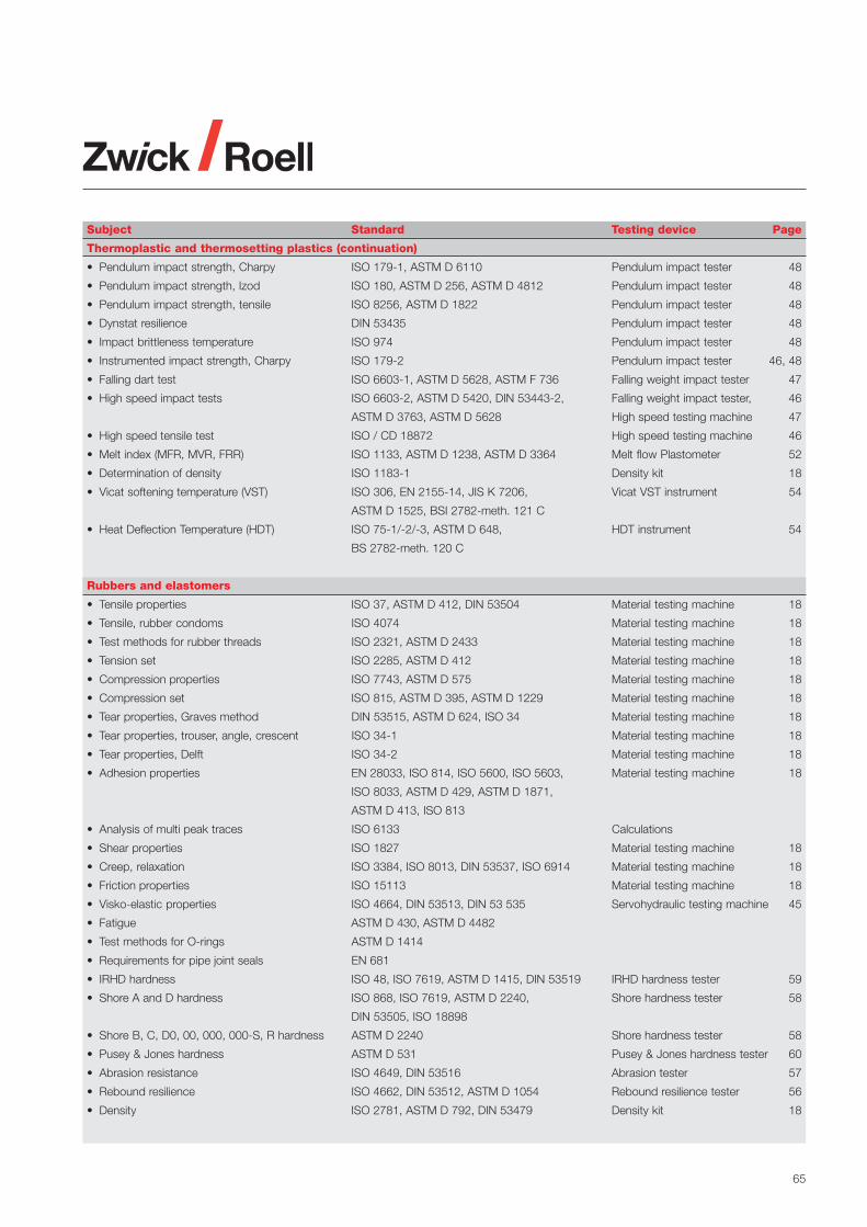
65
Subject Standard Testing device Page
Thermoplastic and thermosetting plastics (continuation)
• Pendulum impact strength, Charpy ISO 179-1, ASTM D 6110 Pendulum impact tester 48
• Pendulum impact strength, Izod ISO 180, ASTM D 256, ASTM D 4812 Pendulum impact tester 48
• Pendulum impact strength, tensile ISO 8256, ASTM D 1822 Pendulum impact tester 48
• Dynstat resilience DIN 53435 Pendulum impact tester 48
• Impact brittleness temperature ISO 974 Pendulum impact tester 48
• Instrumented impact strength, Charpy ISO 179-2 Pendulum impact tester 46, 48
• Falling dart test ISO 6603-1, ASTM D 5628, ASTM F 736 Falling weight impact tester 47
• High speed impact tests ISO 6603-2, ASTM D 5420, DIN 53443-2, Falling weight impact tester, 46
ASTM D 3763, ASTM D 5628 High speed testing machine 47
• High speed tensile test ISO / CD 18872 High speed testing machine 46
• Melt index (MFR, MVR, FRR) ISO 1133, ASTM D 1238, ASTM D 3364 Melt flow Plastometer 52
• Determination of density ISO 1183-1 Density kit 18
• Vicat softening temperature (VST) ISO 306, EN 2155-14, JIS K 7206, Vicat VST instrument 54
ASTM D 1525, BSI 2782-meth. 121 C
• Heat Deflection Temperature (HDT) ISO 75-1/-2/-3, ASTM D 648, HDT instrument 54
BS 2782-meth. 120 C
Rubbers and elastomers
• Tensile properties ISO 37, ASTM D 412, DIN 53504 Material testing machine 18
• Tensile, rubber condoms ISO 4074 Material testing machine 18
• Test methods for rubber threads ISO 2321, ASTM D 2433 Material testing machine 18
• Tension set ISO 2285, ASTM D 412 Material testing machine 18
• Compression properties ISO 7743, ASTM D 575 Material testing machine 18
• Compression set ISO 815, ASTM D 395, ASTM D 1229 Material testing machine 18
• Tear properties, Graves method DIN 53515, ASTM D 624, ISO 34 Material testing machine 18
• Tear properties, trouser, angle, crescent ISO 34-1 Material testing machine 18
• Tear properties, Delft ISO 34-2 Material testing machine 18
• Adhesion properties EN 28033, ISO 814, ISO 5600, ISO 5603, Material testing machine 18
ISO 8033, ASTM D 429, ASTM D 1871,
ASTM D 413, ISO 813
• Analysis of multi peak traces ISO 6133 Calculations
• Shear properties ISO 1827 Material testing machine 18
• Creep, relaxation ISO 3384, ISO 8013, DIN 53537, ISO 6914 Material testing machine 18
• Friction properties ISO 15113 Material testing machine 18
• Visko-elastic properties ISO 4664, DIN 53513, DIN 53 535 Servohydraulic testing machine 45
• Fatigue ASTM D 430, ASTM D 4482
• Test methods for O-rings ASTM D 1414
• Requirements for pipe joint seals EN 681
• IRHD hardness ISO 48, ISO 7619, ASTM D 1415, DIN 53519 IRHD hardness tester 59
• Shore A and D hardness ISO 868, ISO 7619, ASTM D 2240, Shore hardness tester 58
DIN 53505, ISO 18898
• Shore B, C, D0, 00, 000, 000-S, R hardness ASTM D 2240 Shore hardness tester 58
• Pusey & Jones hardness ASTM D 531 Pusey & Jones hardness tester 60
• Abrasion resistance ISO 4649, DIN 53516 Abrasion tester 57
• Rebound resilience ISO 4662, DIN 53512, ASTM D 1054 Rebound resilience tester 56
• Density ISO 2781, ASTM D 792, DIN 53479 Density kit 18

66
Subject Standard Testing device Page
Rubber or plastic coated fabrics
• Tensile properties ISO 1421, ASTM D 751 Material testing machine 18
• Adhesion properties ISO 36, ISO 4637, ISO 4647, ASTM D 413 Material testing machine 18
• Blocking resistance ISO 5978, EN 25978 Material testing machine 18
• Tear resistance ISO 4674, ASTM D 751, DIN 53356 Material testing machine 18
Rigid cellular plastics
• Test methods ISO 9054, ISO 7214 -
• Tensile properties ISO 1926, ASTM D 1623,DIN 53430 Material testing machine 18
• Flexural properties ISO 1209-1/-2, JIS K 7221 Material testing machine 18
• Shear strength ISO 1922, DIN 53427 Material testing machine 18
• Compression properties ISO 844, ASTM D 1621, EN 826 Material testing machine 18
• Compression creep test ISO 7616, ISO 7850 Material testing machine 18
• Thickness measurement EN 12431 Material testing machine 18
• Pendulum impact strength ISO 179 Pendulum impact tester 48
• Density ISO 845, ASTM D 1622 Balance 18
• Tensile strength perpendicular to faces EN 1607, DIN 53292 Materials testing machine 18
Flexible cellular polymeric materials
• Tensile properties ISO 1798, ASTM D 3574-E Material testing machine 18
• Compression properties ISO 3386-1, ISO 3386-2, Material testing machine 18
ASTM D 3574-C, ASTM D 1055
• Indentation properties (hardness) ISO 2439, DIN 53577, DIN 53579-1 Material testing machine 18
ASTM D 3574-B, ASTM D 3579
• Compression load deflection ISO 11752 Material testing machine 18
• Tear strength, trouser specimen ISO 8067, ASTM D 3574-F Material testing machine 18
• Creep in compression ISO 10066, ISO 1856 Material testing machine 18
• Rebound resilience DIN 13014, ISO 8307, ASTM D 3574 Rebound resilience tester 57
• Constant load pounding ISO 3385
• Accelerated ageing tests ISO 2440
• Dynamic cushioning performance ISO 4651 Falling weight impact tester -
• Appearant density ISO 845, ASTM D 3574-A Balance 18
Reinforced plastic composites
• Tensile properties ISO 527-4/-5, ISO 4899, ISO 14129, Material testing machine 18
ASTM D 3039, ASTM D 3916, ASTM D 5083,
DIN 65378, DIN 65466, EN 2561
• Hole opening properties DIN 65562, ASTM D 5961 Material testing machine 18
• Compression properties ISO 14126, DIN 65375, DIN 65380, Material testing machine 18
ASTM D 3410, pr EN 2850, ASTM D 695
• Notched compression strength AITM 1-0008, EN 6036 Materials testing machine 18
• Flexural properties ISO 14125, ASTM D 4476, DIN 53390 Material testing machine 18
• Interlaminar shear strength ISO 14130, EN 2377, EN 2563, Material testing machine 18
JIS K 7078, DIN 65148, ASTM D 4475
• Shear strength ASTM D 5379, ASTM D 3846, Material testing machine 18
ASTM D 3914, DIN 53399-2
• Shear modulus ISO 14129, ASTM D 3518, JIS K 7079 Material testing machine 18
• Fracture toughness, Kc, Gc (LEFM),J-R ISO 13586, NASA R.P.1092, Material testing machine 18
ISO 17281, ASTM D 5045, ASTM D 6068,
ASTM D 6671, ASTM D 5528
• Fatigue properties ISO/DIS 13003, ASTM D 3479 Servohydraulic testing machine 18
• Compression After Impact (CAI) ASTM D 7136, AITM 1-0010, BSS 7260 Falling weight tester 47
CRAG method 403

67
Subject Standard Testing device Page
Thin sheetings and films
• Tensile properties ISO 527-3, ASTM D 882, ASTM D 5323 Material testing machine 18
• Tear resistance, Graves, angle specimen ISO 34, DIN 53515 Material testing machine 18
• Tear resistance, trouser specimen ISO 6383-1, ASTM D 1004, ASTM D 1938 Material testing machine 18
• Tear resistance, trapezoidal specimen EN 495-2, DIN 53363 Material testing machine 18
• Blocking strength ISO 11502, DIN 53366, ASTM D 3354 Material testing machine 18
• Puncture tests EN 14477, ASTM D 5748, ASTM F1306 Material testing machine 18
• Pendulum impact strength, tensile ISO 8256, ASTM D 1822 Pendulum impact tester 48
• Impact resistance, free falling dart ISO 7765-1/-2, ASTM D 4272 Falling weight impact tester 47
ASTM D 1709, ASTM D 3763, JIS K 7124
DIN 53373
• Coefficient of friction ISO 8295, ASTM D 1894, JIS K 7125, Material testing machine 18
DIN 53375
Plastic piping
• Specifications for pipes EN 1555, EN 1852
• Tensile properties ISO 6259-1/-2/-3, ISO 8521, ISO 8513, Material testing machine 18
ISO 8533, ASTM D 2105, ASTM D 2290,
EN 1393, EN 1394
• Compression properties EN 802, EN 1446, ISO/DIS 4435, Material testing machine 18
DIN 53769-3, ASTM D 2412
• Flexural strength EN 12100 Material testing machine 18
• Creep test ISO 7684, EN 761, EN 1862 Material testing machine 18
• Ring stiffness ISO 9969, ISO 9968, ISO 13967, ISO 10466, Material testing machine 18
ISO 10471, EN 1226, EN 1227, EN 1228,
ASTM D 5365
• Cyclic compression test ASTM D 2143
• Vicat softening temperature EN 727 Vicat VST instrument 54
• Impact characteristics EN 744, EN 1411, EN 12061, ISO 3127, Falling weight impact tester 47/48
ASTM D 2444, ISO 7628 Pendulum impact tester
• Melt flow index ISO 4440-1/-2 Melt flow Plastometer 52
Adhesives
• Tensile properties (butt joints) ISO 6922, EN 26922, EN 1940, EN 1941, Material testing machine 18
EN 14410
• Peel resistance ISO 4578, ISO 8510-1/-2, ISO 11339 Material testing machine 18
EN 1464, EN 1939, EN 28510-1/-2, EN 60454-2
• Contact adhesion EN 1945
• Shear strength ISO 4587, ISO 10123, EN 1465, ISO 11003, Material testing machine 18
ISO 13445, ASTM D 3163, ASTM D 3164
• Bending-shear strength ISO 15108 Material testing machine 18
• Creep properties ISO 15109 Material testing machine 18
• Shear impact strength ISO 9653, EN 29653
• Fatigue properties ISO 9664 Servohydraulic testing machine 45
• Resistance to flow ISO 14678

Zwick Asia Pte Ltd.25 International Business Park#04-17 German CentreSingapore 609916 · SingaporePhone ++65 6 899 5010Fax ++65 6 899 [email protected]
Zwick USA1620 Cobb International BoulevardSuite #1Kennesaw, GA 30152 · USAPhone ++1 770 420 6555Fax ++1 770 420 [email protected]
Zwick Testing Machines Ltd.Southern AvenueLeominster, Herefordshire HR6 OQH Great BritainPhone ++44 1568-61 52 01Fax ++44 1568-61 26 [email protected]
Zwick France S.a.r.l.B.P. 45045F-95912 Roissy CDG Cedex FrancePhone ++33 1-48 63 21 40Fax ++33 1-48 63 84 [email protected]
Zwick Ibérica Equipos de Ensayos S.L.Marcus Porcius, 1Pol. Les Guixeres, s/n Edificio BCIN08915 Badalona (Barcelona) - SpainPhone ++34 934 648 002 Fax ++34 934 648 [email protected]