term project presentation_final
TRANSCRIPT
EN.565.745: SLOPE STABILITY AND EARTH RETAINING STRUCTURESDR. XIN CHEN
Term ProjectSpring 2015
“EXTERNAL STABILITY EVALUATION OF DESIGN ALTERNATIVES FOR CULVERT REPLACEMENT”
Shayan AminJohn O’Donald
Purpose
The purpose of this presentation is to demonstrate our knowledge of slope stability and stabilization methods as a product of this course
Term project considers a hypothetical project to replace a failed culvert
The focus will be on the components of the proposed design that will require stability evaluation
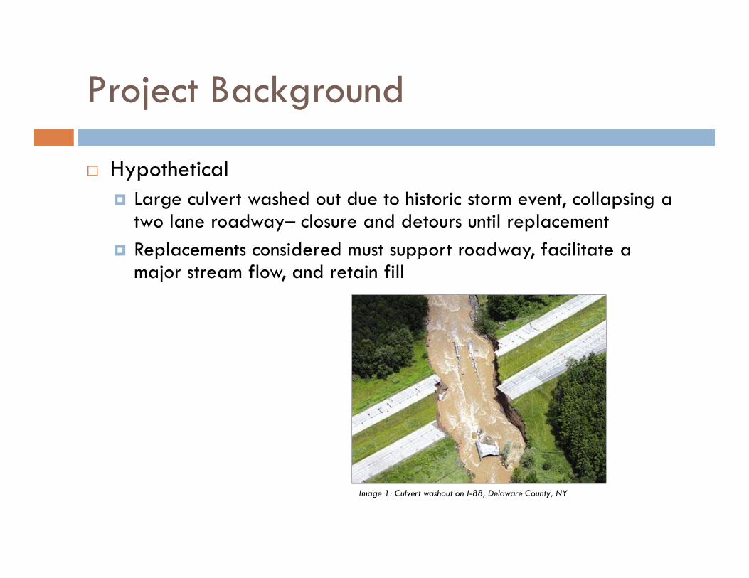
Project Background
Hypothetical Large culvert washed out due to historic storm event, collapsing a
two lane roadway– closure and detours until replacement Replacements considered must support roadway, facilitate a
major stream flow, and retain fill
Image 1: Culvert washout on I-88, Delaware County, NY
Site Parameters
Collapsed culvert was 20’-7” x 13’-2” SPPA 40’-0” roadway typical section – (2) 12’-0” lanes and
(2) 8’-0” shoulders Limited ROW outside of roadway boundaries Stream invert 20’-0” below proposed top of roadway
elevation H&H analysis performed to determine required
hydraulics Geotechnical investigation performed to determine soil
parameters
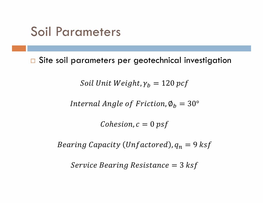
Soil Parameters
Site soil parameters per geotechnical investigation
, 120
, ∅ 30°
, 0
, 9
3
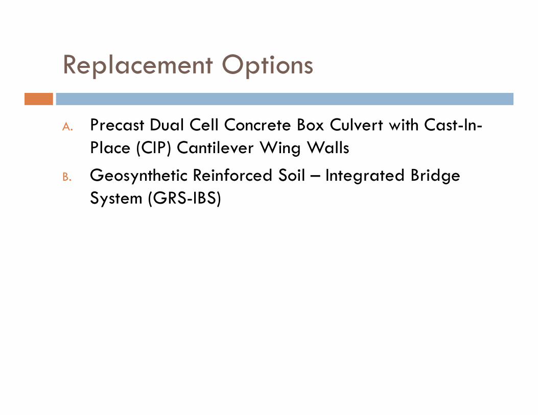
Replacement Options
A. Precast Dual Cell Concrete Box Culvert with Cast-In-Place (CIP) Cantilever Wing Walls
B. Geosynthetic Reinforced Soil – Integrated Bridge System (GRS-IBS)
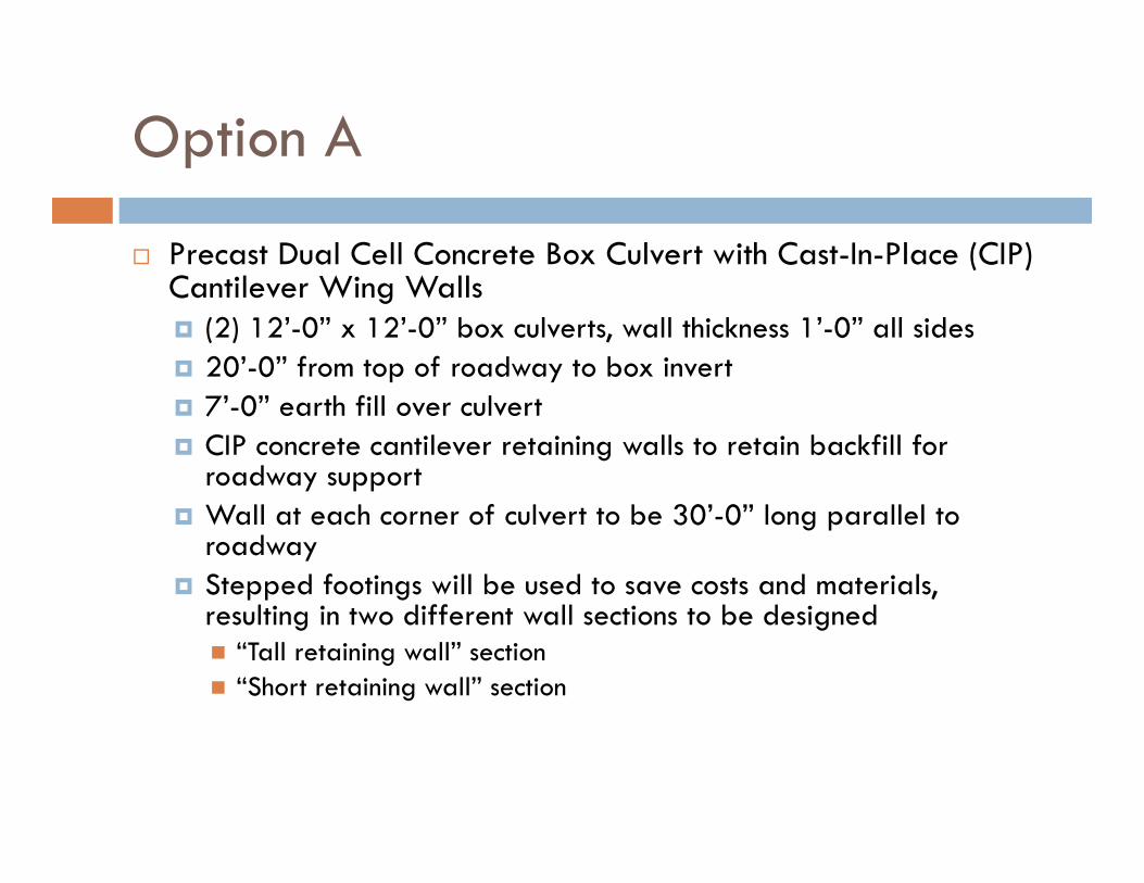
Option A
Precast Dual Cell Concrete Box Culvert with Cast-In-Place (CIP) Cantilever Wing Walls (2) 12’-0” x 12’-0” box culverts, wall thickness 1’-0” all sides 20’-0” from top of roadway to box invert 7’-0” earth fill over culvert CIP concrete cantilever retaining walls to retain backfill for
roadway support Wall at each corner of culvert to be 30’-0” long parallel to
roadway Stepped footings will be used to save costs and materials,
resulting in two different wall sections to be designed “Tall retaining wall” section “Short retaining wall” section
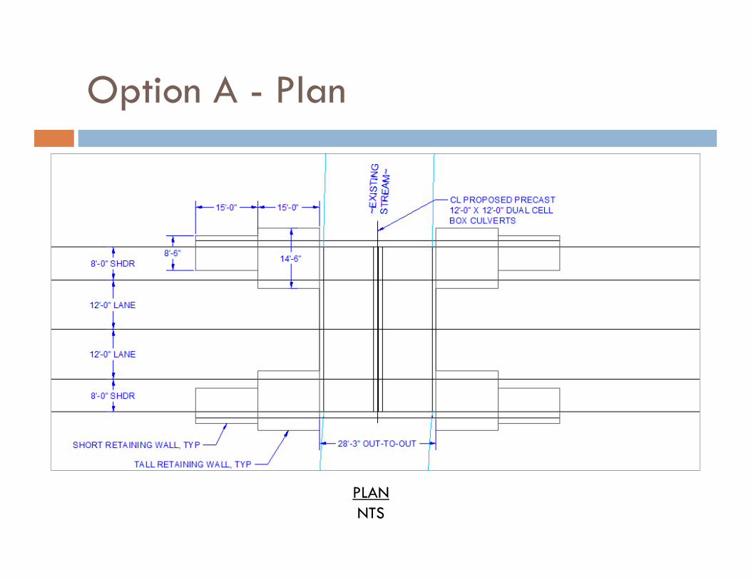
Option A - Plan
PLANNTS
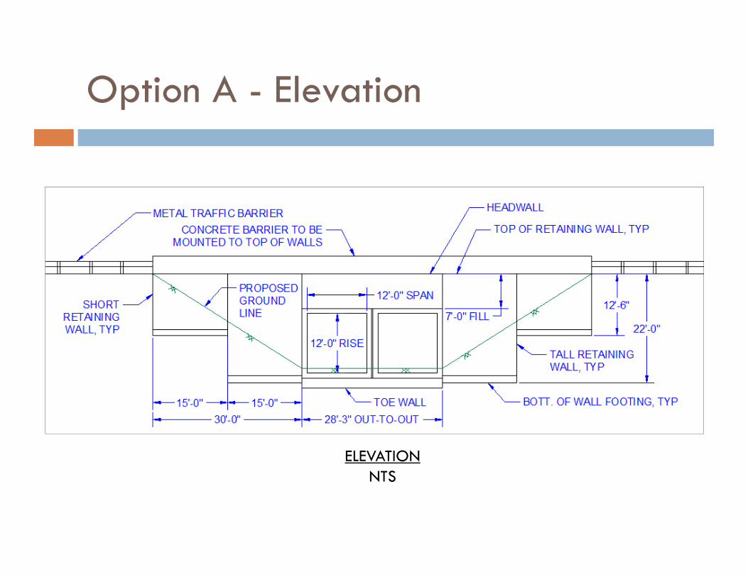
Option A - Elevation
ELEVATIONNTS
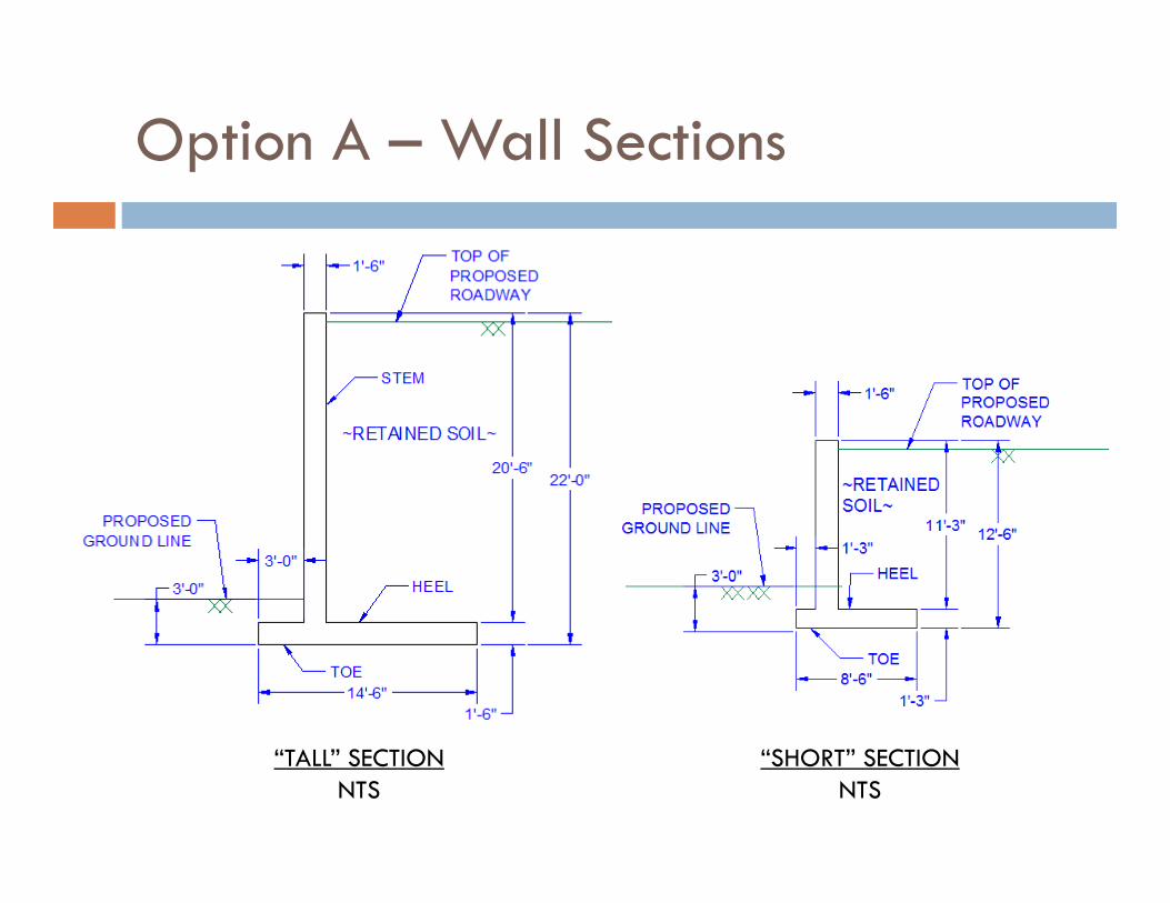
Option A – Wall Sections
“TALL” SECTIONNTS
“SHORT” SECTIONNTS
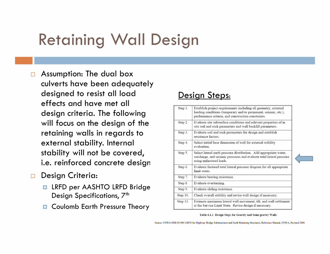
Retaining Wall Design
Assumption: The dual box culverts have been adequately designed to resist all load effects and have met all design criteria. The following will focus on the design of the retaining walls in regards to external stability. Internal stability will not be covered, i.e. reinforced concrete design
Design Criteria: LRFD per AASHTO LRFD Bridge
Design Specifications, 7th
Coulomb Earth Pressure Theory
Design Steps:
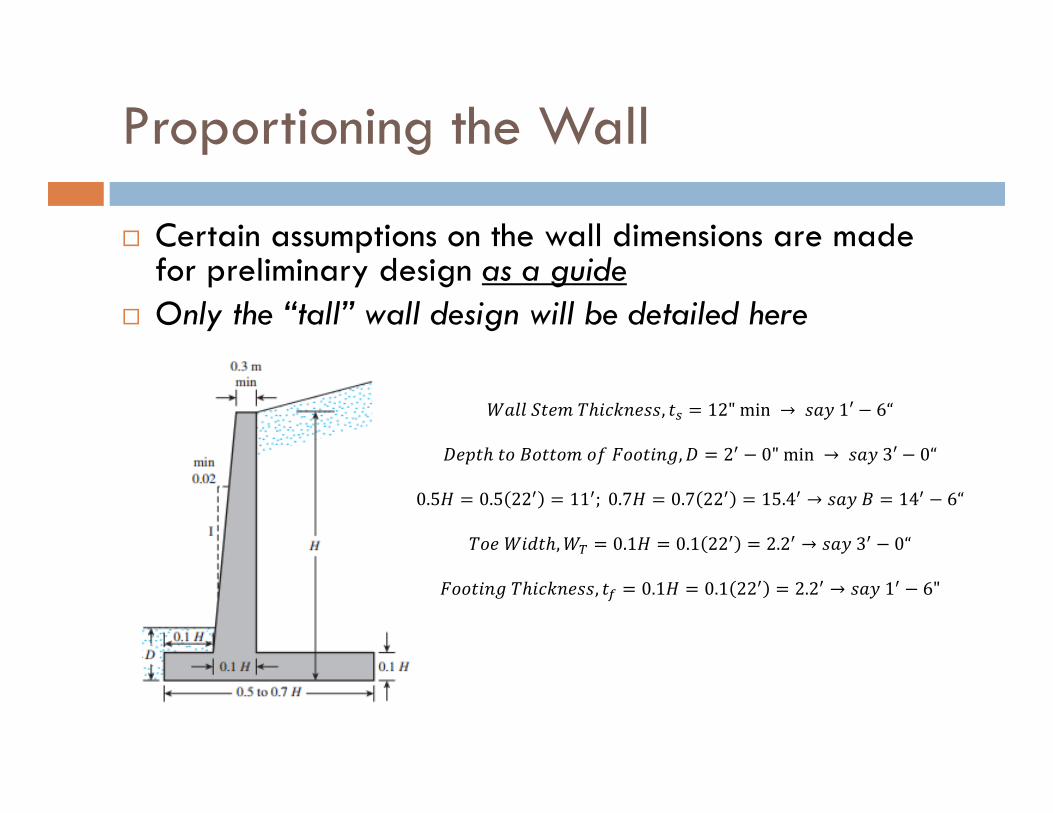
Proportioning the Wall
Certain assumptions on the wall dimensions are made for preliminary design as a guide
Only the “tall” wall design will be detailed here
, 12"min → 1′ 6“
, 2 0"min → 3′ 0“
0.5 0.5 22 11 ; 0.7 0.7 22 15.4 → 14 6“
, 0.1 0.1 22 2.2 → 3 0“
, 0.1 0.1 22 2.2 → 1 6"
Check External Stability
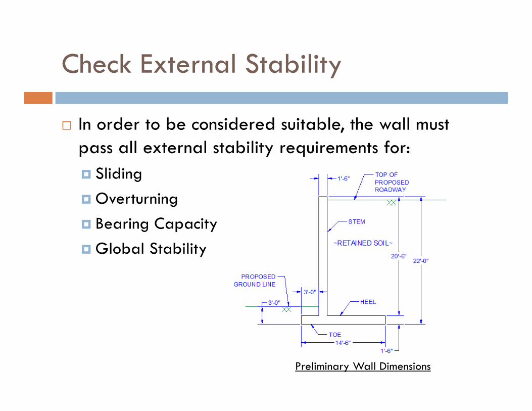
In order to be considered suitable, the wall must pass all external stability requirements for: Sliding Overturning Bearing Capacity Global Stability
Preliminary Wall Dimensions
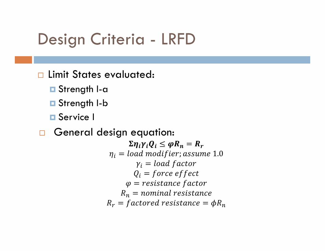
Design Criteria - LRFD
Limit States evaluated: Strength I-a Strength I-b Service I
General design equation:
; 1.0
Design Criteria - LRFD
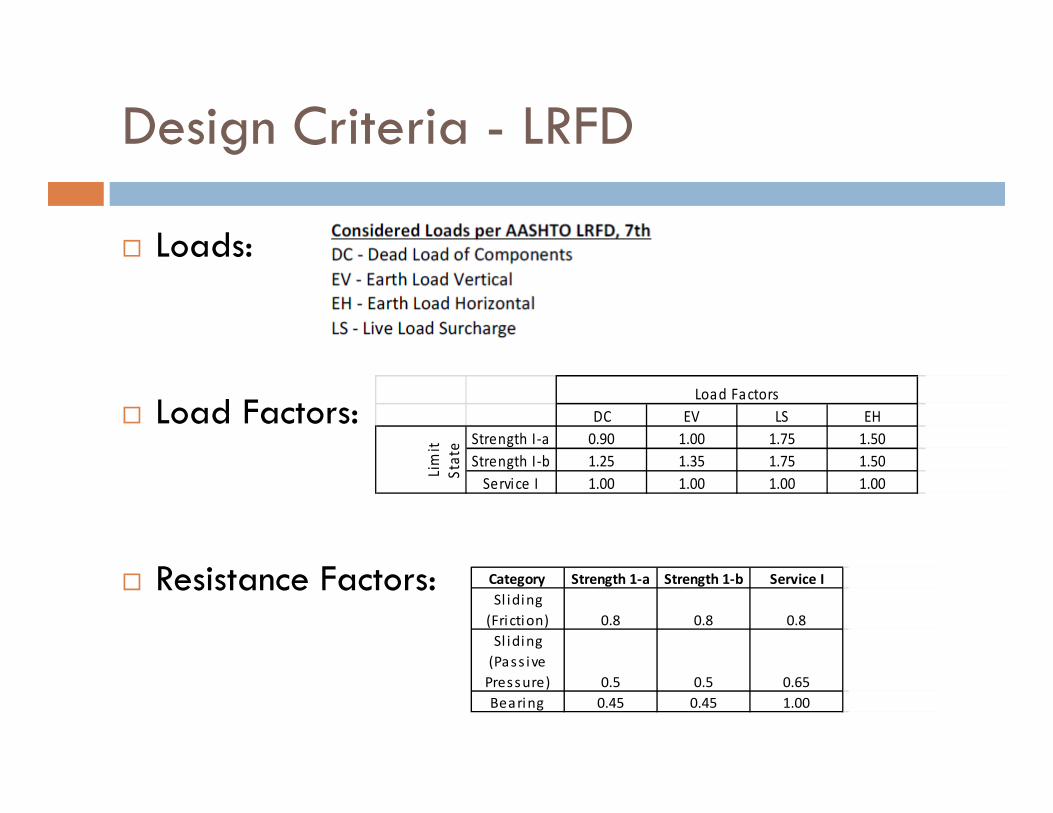
Loads:
Load Factors:
Resistance Factors:
DC EV LS EHStrength I‐a 0.90 1.00 1.75 1.50Strength I‐b 1.25 1.35 1.75 1.50Service I 1.00 1.00 1.00 1.00
Load Factors
Limit
State
Category Strength 1‐a Strength 1‐b Service ISl iding (Friction) 0.8 0.8 0.8Sl iding (Pass ive Pressure) 0.5 0.5 0.65Bearing 0.45 0.45 1.00
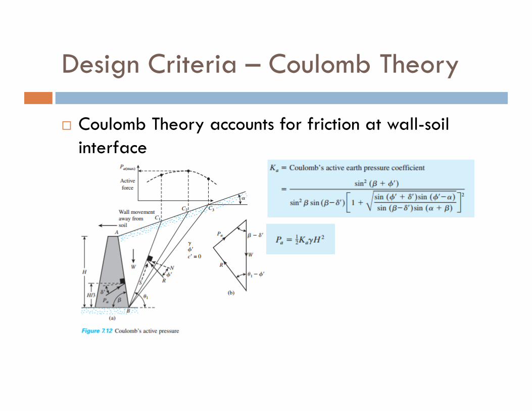
Design Criteria – Coulomb Theory
Coulomb Theory accounts for friction at wall-soil interface
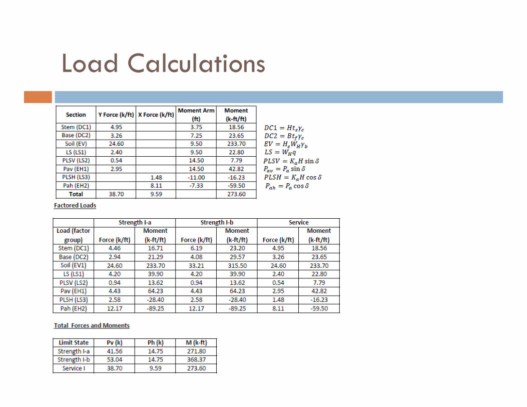
Load Calculations
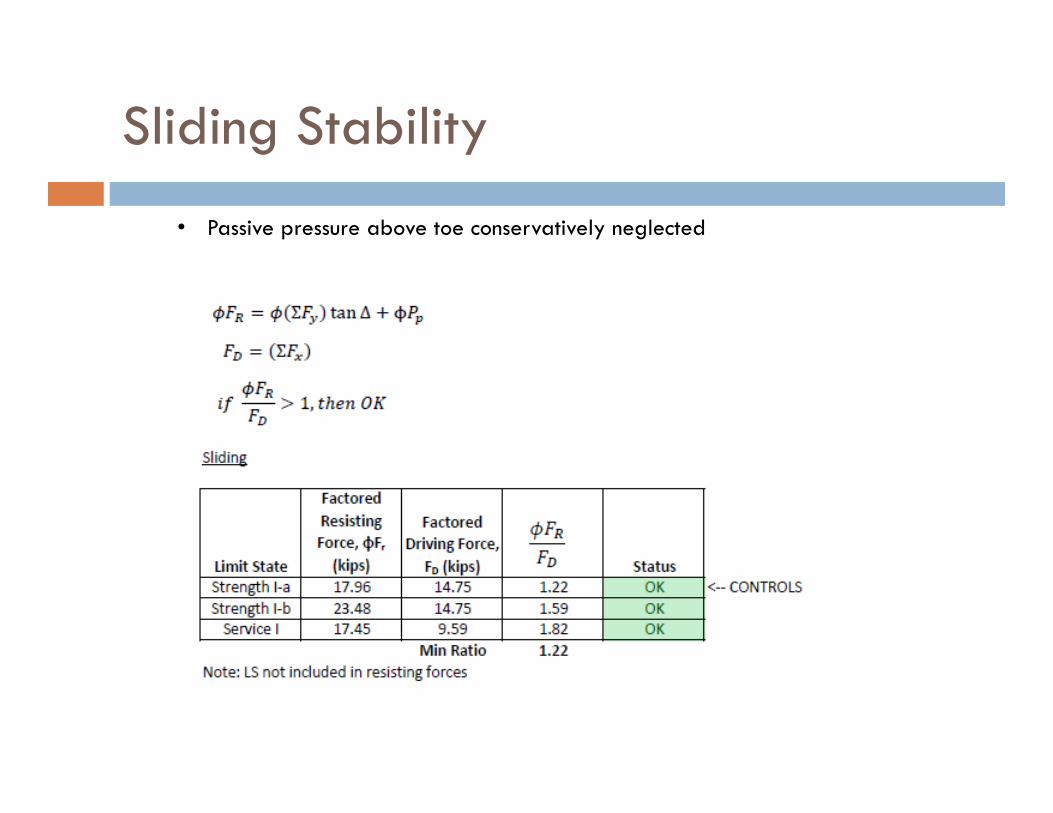
Sliding Stability
• Passive pressure above toe conservatively neglected
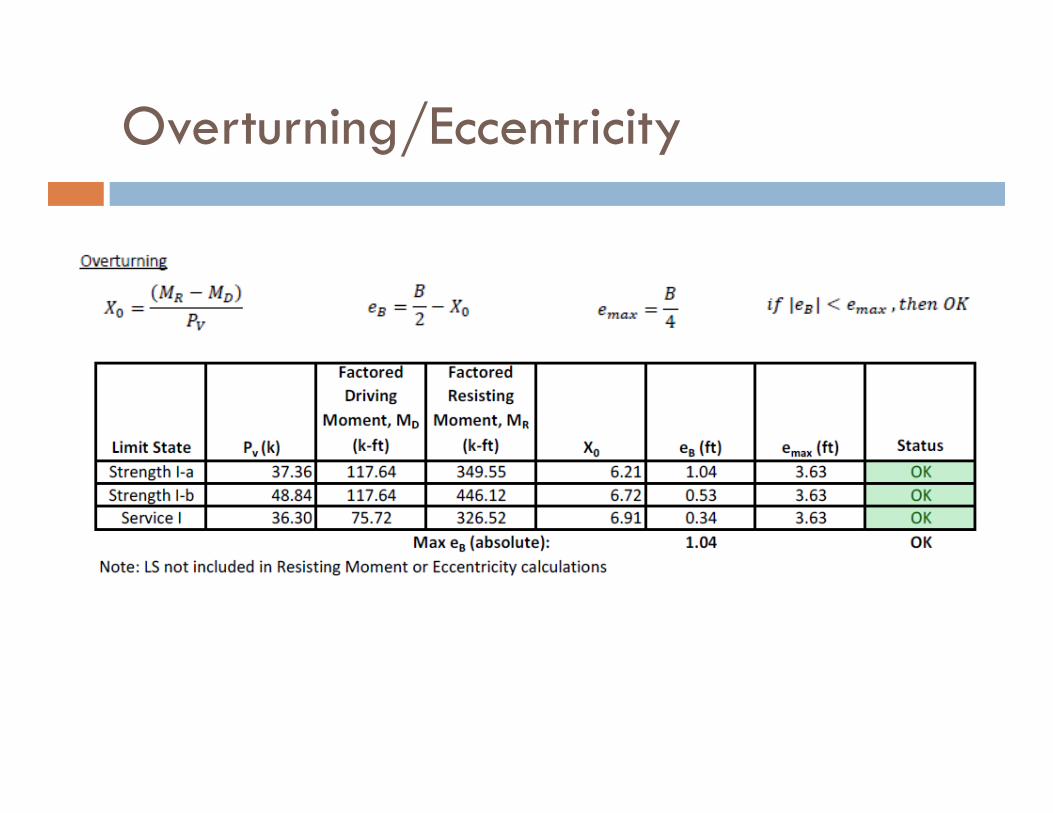
Overturning/Eccentricity
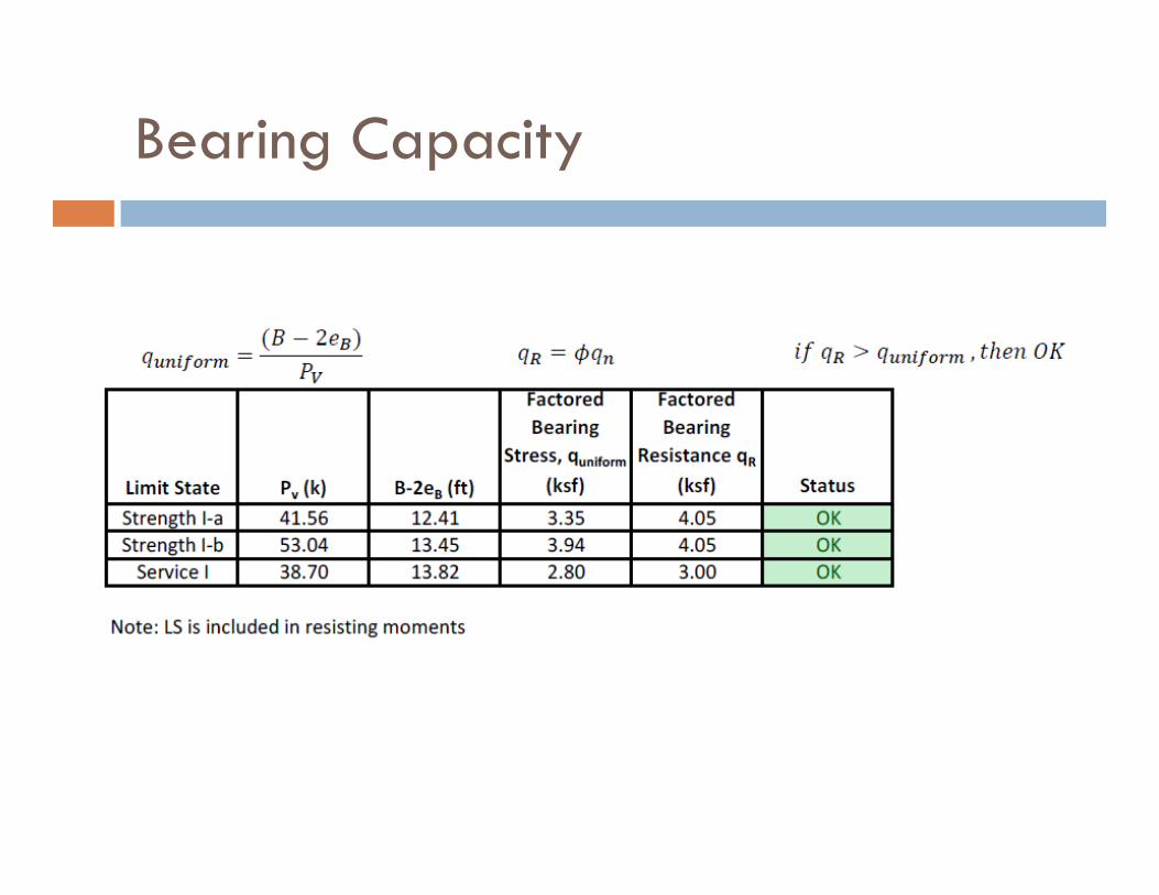
Bearing Capacity
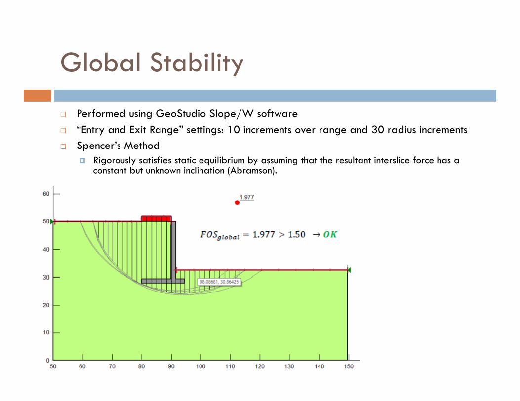
Global Stability
Performed using GeoStudio Slope/W software “Entry and Exit Range” settings: 10 increments over range and 30 radius increments Spencer’s Method
Rigorously satisfies static equilibrium by assuming that the resultant interslice force has a constant but unknown inclination (Abramson).
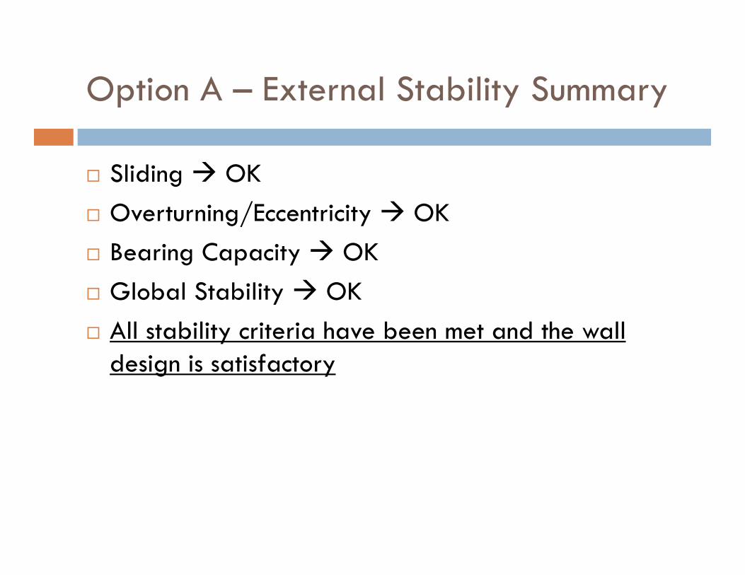
Option A – External Stability Summary
Sliding OK Overturning/Eccentricity OK Bearing Capacity OK Global Stability OK All stability criteria have been met and the wall
design is satisfactory
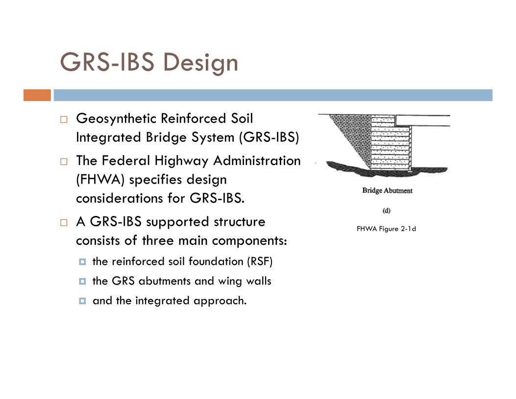
GRS-IBS Design
Geosynthetic Reinforced Soil Integrated Bridge System (GRS-IBS)
The Federal Highway Administration (FHWA) specifies design considerations for GRS-IBS.
A GRS-IBS supported structure consists of three main components: the reinforced soil foundation (RSF)
the GRS abutments and wing walls
and the integrated approach.
FHWA Figure 2-1d
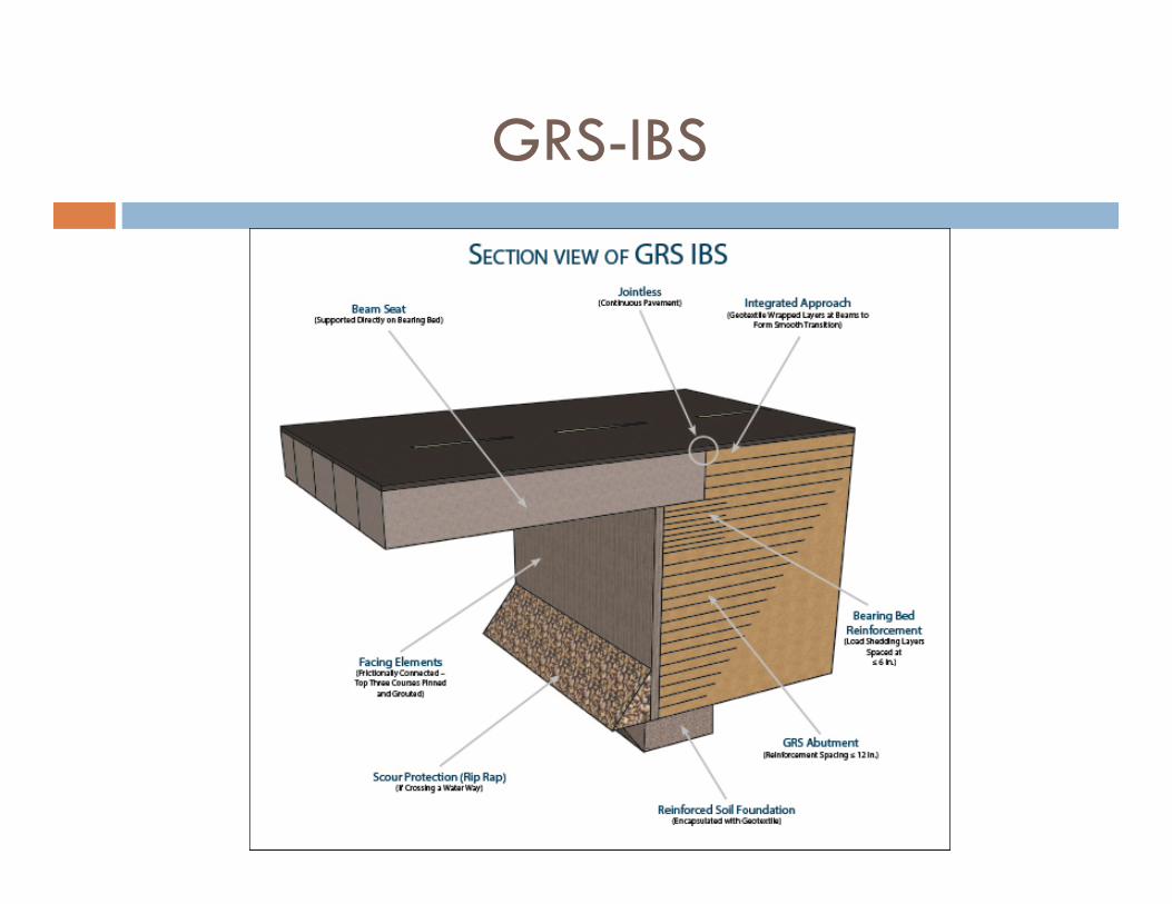
GRS-IBS
Important Design Considerations
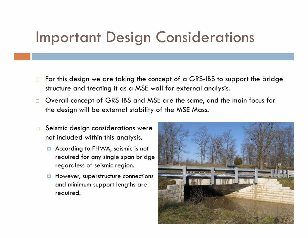
Seismic design considerations were not included within this analysis. According to FHWA, seismic is not
required for any single span bridge regardless of seismic region.
However, superstructure connections and minimum support lengths are required.
For this design we are taking the concept of a GRS-IBS to support the bridge structure and treating it as a MSE wall for external analysis.
Overall concept of GRS-IBS and MSE are the same, and the main focus for the design will be external stability of the MSE Mass.
Assumptions Made
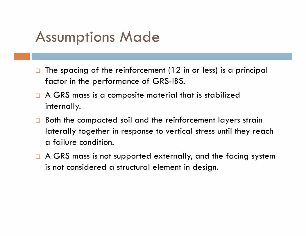
The spacing of the reinforcement (12 in or less) is a principal factor in the performance of GRS-IBS.
A GRS mass is a composite material that is stabilized internally.
Both the compacted soil and the reinforcement layers strain laterally together in response to vertical stress until they reach a failure condition.
A GRS mass is not supported externally, and the facing system is not considered a structural element in design.
Assumptions Made (Cont.)
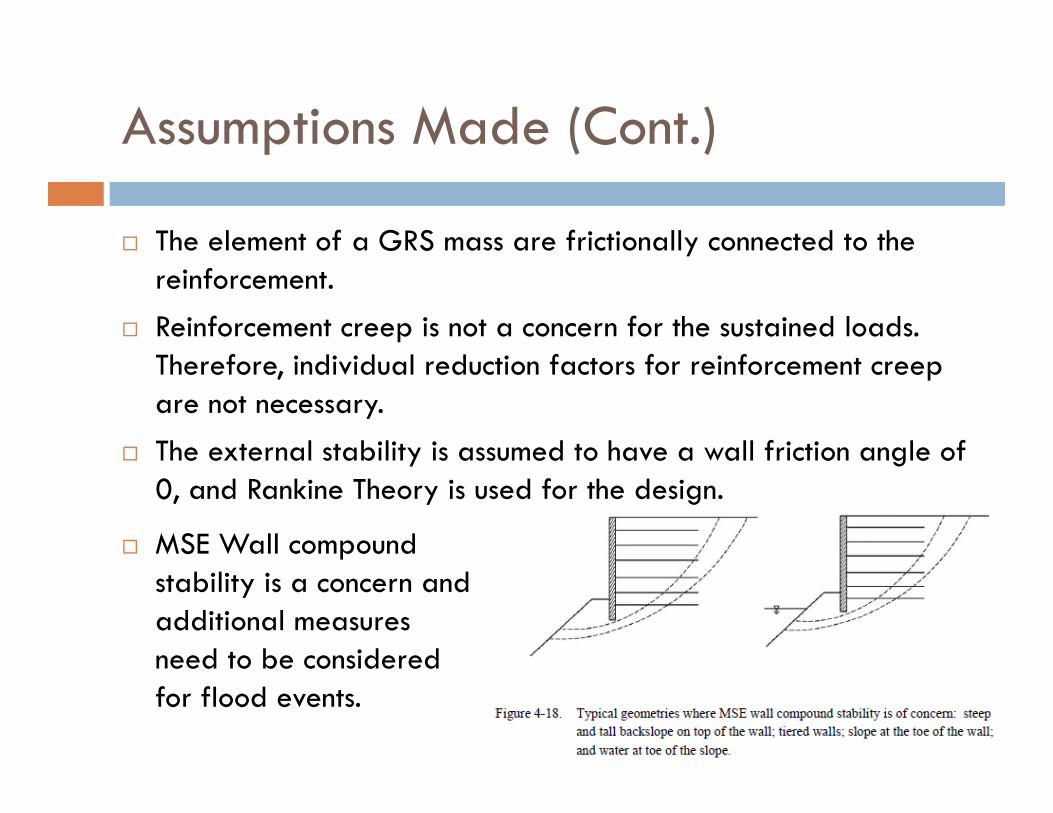
The element of a GRS mass are frictionally connected to the reinforcement.
Reinforcement creep is not a concern for the sustained loads. Therefore, individual reduction factors for reinforcement creep are not necessary.
The external stability is assumed to have a wall friction angle of 0, and Rankine Theory is used for the design.
MSE Wall compound stability is a concern and additional measures need to be considered for flood events.
MSE Wall External Stability
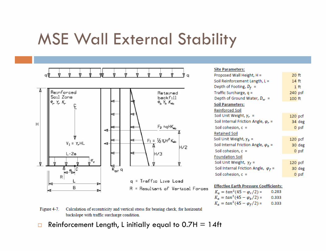
Reinforcement Length, L initially equal to 0.7H = 14ft
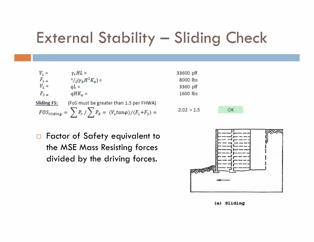
External Stability – Sliding Check
Factor of Safety equivalent to the MSE Mass Resisting forces divided by the driving forces.
External Stability – Overturning Check
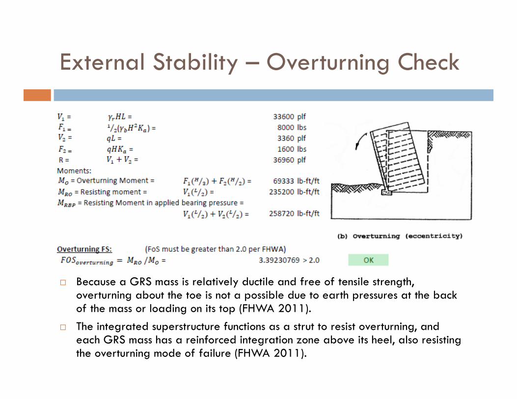
Because a GRS mass is relatively ductile and free of tensile strength, overturning about the toe is not a possible due to earth pressures at the back of the mass or loading on its top (FHWA 2011).
The integrated superstructure functions as a strut to resist overturning, and each GRS mass has a reinforced integration zone above its heel, also resisting the overturning mode of failure (FHWA 2011).
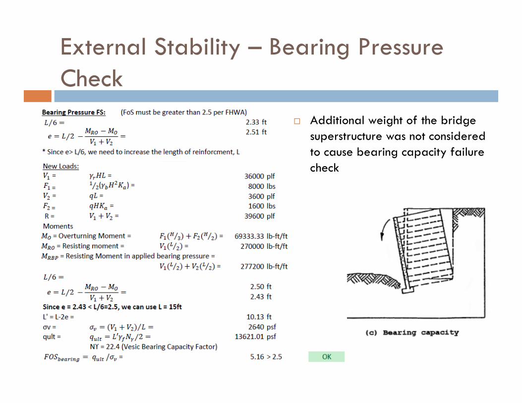
External Stability – Bearing Pressure Check
Additional weight of the bridge superstructure was not considered to cause bearing capacity failure check
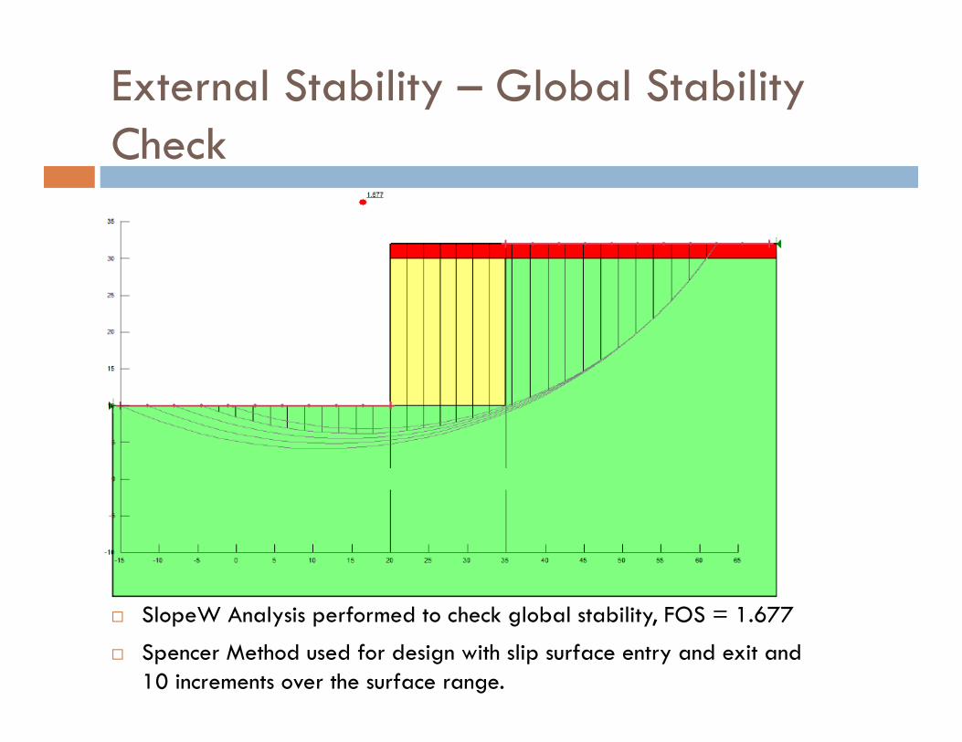
External Stability – Global Stability Check
SlopeW Analysis performed to check global stability, FOS = 1.677
Spencer Method used for design with slip surface entry and exit and 10 increments over the surface range.
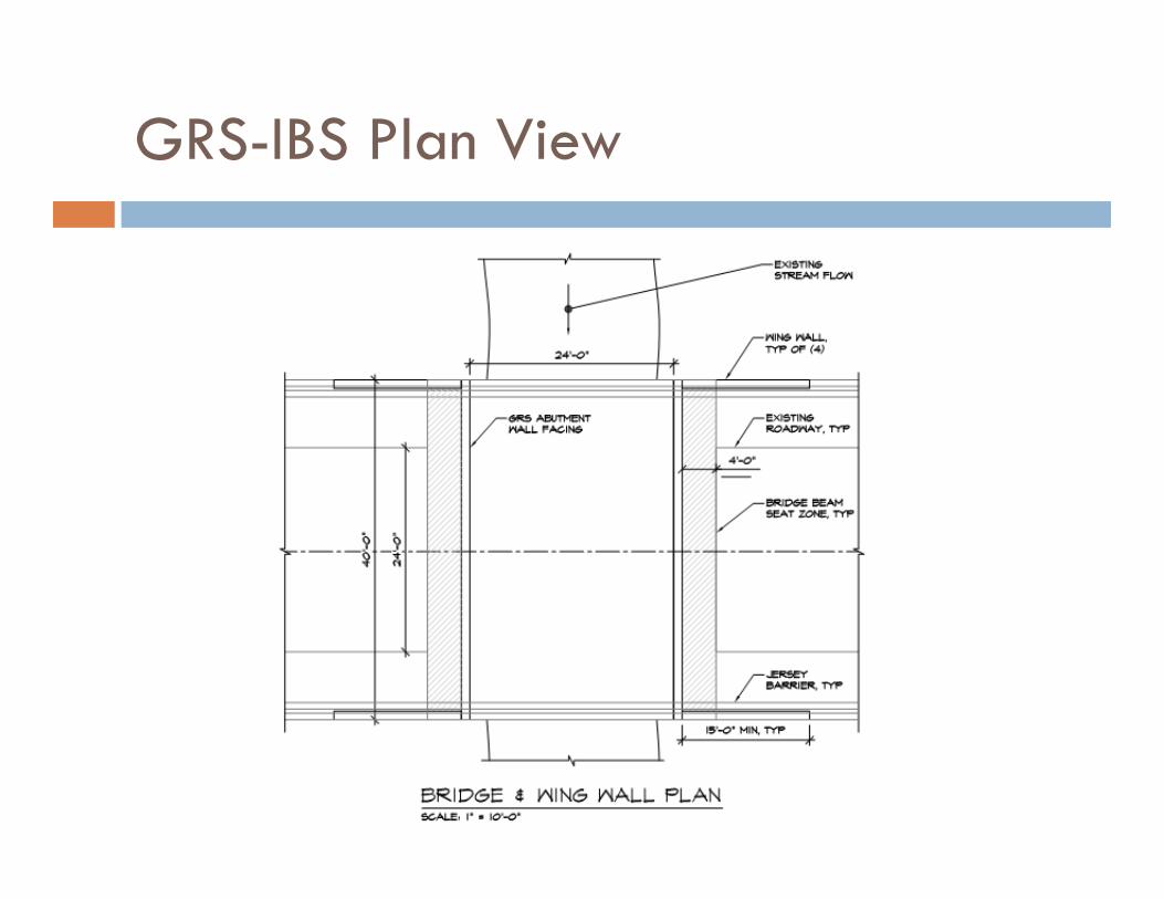
GRS-IBS Plan View
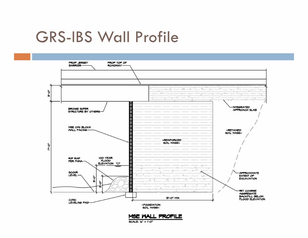
GRS-IBS Wall Profile
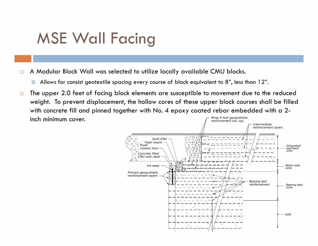
MSE Wall Facing
A Modular Block Wall was selected to utilize locally available CMU blocks. Allows for consist geotextile spacing every course of block equivalent to 8”, less than 12”.
The upper 2.0 feet of facing block elements are susceptible to movement due to the reduced weight. To prevent displacement, the hollow cores of these upper block courses shall be filled with concrete fill and pinned together with No. 4 epoxy coated rebar embedded with a 2-inch minimum cover.
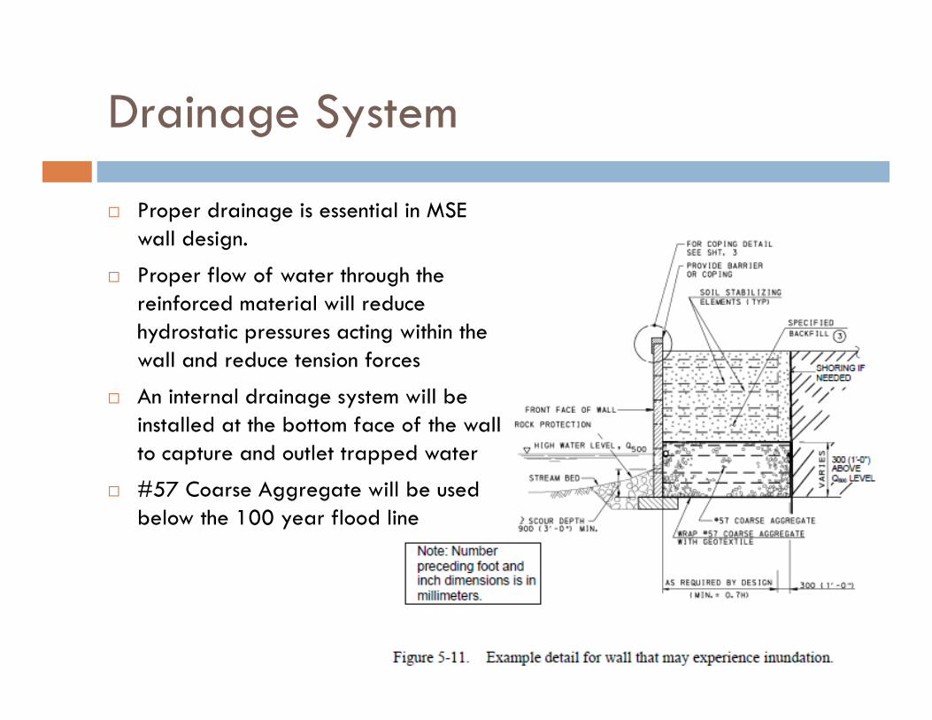
Drainage System
Proper drainage is essential in MSE wall design.
Proper flow of water through the reinforced material will reduce hydrostatic pressures acting within the wall and reduce tension forces
An internal drainage system will be installed at the bottom face of the wall to capture and outlet trapped water
#57 Coarse Aggregate will be used below the 100 year flood line
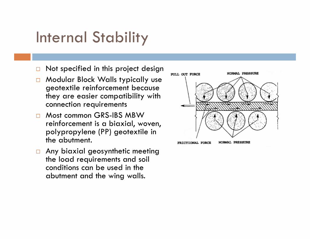
Internal Stability
Not specified in this project design Modular Block Walls typically use
geotextile reinforcement because they are easier compatibility with connection requirements
Most common GRS-IBS MBW reinforcement is a biaxial, woven, polypropylene (PP) geotextile in the abutment.
Any biaxial geosynthetic meeting the load requirements and soil conditions can be used in the abutment and the wing walls.
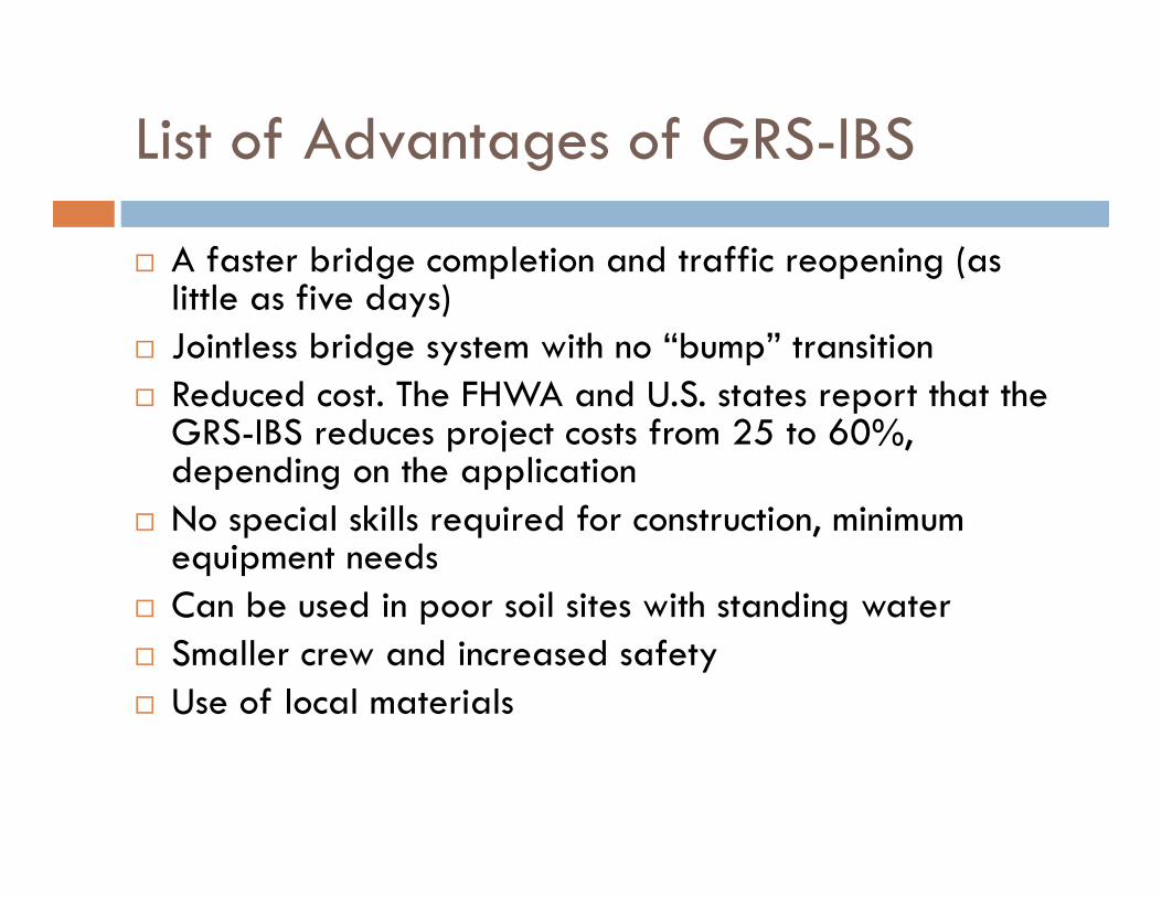
List of Advantages of GRS-IBS
A faster bridge completion and traffic reopening (as little as five days)
Jointless bridge system with no “bump” transition Reduced cost. The FHWA and U.S. states report that the
GRS-IBS reduces project costs from 25 to 60%, depending on the application
No special skills required for construction, minimum equipment needs
Can be used in poor soil sites with standing water Smaller crew and increased safety Use of local materials
Cost Comparison
An in-depth cost analysis was not performed but the following considerations were used in the final determination: MSE walls range from $30-65 per ft^2 of wall face
According to FHWA, MSE walls result in savings of 25-60% compared to conventional reinforced concrete retaining walls. Assuming the installation time and cost of the box culvert
and bridge structure are relatively the same.
References
AASHTO LRFD Bridge Design Specifications, Customary U.S. Units, 7th Edition, with 2015 Interim Revisions Abramson, Lee W., Thoms S. Lee, Sunil Sharma, Glenn M. Boyce. Slope Stability and Stabilization Methods.
2nd ed. New Jersey: Wiley, 2002. Print. Berg, R.R., Christopher, B.R., and Samtani, N.C. (2009) Design of Mechanically Stabilized Earth Walls and
Reinforced Soil Slopes, U.S. Department of Transportation, Federal Highway Administration, Washington DC, FHWA NHI-09-083 and FHWA GEC 011, 668 p.
Breskin, P.E., Kalia. "State Route 32 Strut Bremen, Maine." Geotechnical Design Report (2012): 50. Contech Engineered Solutions Structural Plate Design Guide, 5th Edition Das, Braja. Principles of Foundation Engineering. Seventh Edition ed. Global Engineering, 2011. 794. Print. FHWA-NHI-05-094-LRFD for Highway Bridge Substructures and Earth Retaining Structures,
Reference Manual, FHWA, Revised 2006 "GRS-IBS." Accelerating Innovation. Federal Highway Administration, 12 May 2012. Web.
<http://www.fhwa.dot.gov/everydaycounts/technology/grs_ibs/>. Von Handorf, P.E., Chris. "GRS-IBS: The 5-Day Wonder." National Precast Concrete Association, 9 Apr.
2013. Web. <http://precast.org/2013/04/grs-ibs-the-5-day-wonder/>. Yamin-Garone, Mary S. "Record Rainfall Destroys Section of New York's I-88." Construction
Equipment Guide, 12 July 2006. Web. 2 May 2015. <http://www.constructionequipmentguide.com/Record-Rainfall-Destroys-Section-of-New-Yorks-I-88/7191/>.