templating of self-alignment patterns of anisotropic gold nanoparticles on ordered swnt...
TRANSCRIPT
Published: August 19, 2011
r 2011 American Chemical Society 3718 dx.doi.org/10.1021/am2009019 |ACS Appl. Mater. Interfaces 2011, 3, 3718–3724
RESEARCH ARTICLE
www.acsami.org
Templating of Self-Alignment Patterns of Anisotropic GoldNanoparticles on Ordered SWNT MacrostructuresBudhadipta Dan,†,§ Tyler B. Wingfield,§ Julian S. Evans,§ Francesca Mirri,‡ Cary L. Pint,†Matteo Pasquali,‡,*and Ivan I. Smalyukh§,^,*†Department of Physics and Astronomy, ‡Department of Chemical and Biomolecular Engineering, and Department of Chemistry,R.E. Smalley Institute for Nanoscale Science & Technology, Rice University, 6100 Main Street, Houston, Texas 77005, United States§Department of Physics and Liquid Crystal Materials Research Center, University of Colorado, 2000 Colorado Ave, Boulder,Colorado 80309, United States
^Renewable and Sustainable Energy Institute, University of Colorado and National Renewable Energy Laboratory, Boulder,Colorado 80309, United States
bS Supporting Information
Metallic nanoparticles have been the subject of intenseresearch because of their unusual electro-optical properties
and a broad range of potential applications.1,2 Current researchtoward nanoparticles for metamaterial applications is primarilyfocused in two directions: synthesis and ordered assembly.Synthesis involves designing new methods for fabrication ofnanoparticles from a variety of materials, with varied anisotropicshapes, sizes, and aspect ratios. Particles are being tailored topossess highly tunable plasmonic and optoelectronic propertiesaimed for specific advanced applications. Ordered assemblyentails deposition of nanoparticles on surfaces, incorporationinto bulk liquid crystalline media, or chemically mediated crystal-lization in an organized manner so as to leverage the uniqueproperties of individual nanoparticles collectively and attainfunctional behavior on macroscopic scales. Gold nanorods(GNRs) and polygonal nanoplatelets are a particularly interest-ing class of nanoparticles because their surface plasmon reso-nance (SPR) depends on polarization and can be tuned across thevisible and near IR spectrum by changing the GNR aspect ratio.3
Promising GNR applications include plasmonic enhancement ofphotoconversion in photovoltaics,4�6 surface enhanced Ramanscattering (SERS)-based detection and imaging,7,8 biological
imaging and therapy,9�11 and optical metamaterials;12,13 large-scale ordered assembly of GNRs is a critical step for thedevelopment of many of these applications.
Recent advances in ordered assembly and nanoscale align-ment of GNRs include incorporation into lyotropic liquidcrystals,12 stretched polymer films,14,15 electric field drivenalignment in a liquid medium,16 colloidal self-assembly,17,18
and deposition onto patterned surfaces.19 In most cases,however, the substrates or surrounding material (for bulkincorporation) possess minimal or no functionality; the lackof essential properties like electrical conductivity, mechanicalstrength, or chemical durability often limits the range of possibleapplications for these hybrid materials.
Single-walled carbon nanotubes (SWNTs) offer a promisingalternative in this context. SWNTs offer the functional andstructural features of high performance polymers,20 coupled withsuperior electro-optical properties and chemical inertness.21
Their nanoscale diameter combined with high aspect ratio
Received: July 8, 2011Accepted: August 19, 2011
ABSTRACT: We report a simple and versatile technique fororiented assembly of gold nanorods on aligned single-walledcarbon nanotube (SWNT) macrostructures, such as thin nano-tube films and nanotube fibers. The deposition and assembly isaccomplished via drop drying of dilute gold nanorod suspensionson SWNTmacrostructures under ambient conditions. Guided byanisotropic interactions, gold nanorods, and polygonal plateletsspontaneously align with SWNTs, resulting inmacroscopic arraysof locally ordered nanorods supported on aligned SWNT sub-strates. SEM reveals that the scalar order parameter of rods relative to the local average SWNT alignment is 0.7 for rods on SWNTfilms and 0.9 for rods on SWNT fibers. This self-alignment is enabled by anisotropic gold nanoparticle�SWNT interactions and isobserved for a wide range of nanoparticles, including nanorods with aspect ratios ranging from 2�35, thin gold triangular and otherpolygonal platelets. The plasmonic properties of aligned gold nanorods together with superior electronic, chemical and mechanicalproperties of SWNTs make these hybrid nanocomposites valuable for the design of self-assembled multifunctional optoelectronicmaterials and optical metamaterials.
KEYWORDS: gold nanorods, SWNT, films, fibers, template, aligned arrays
3719 dx.doi.org/10.1021/am2009019 |ACS Appl. Mater. Interfaces 2011, 3, 3718–3724
ACS Applied Materials & Interfaces RESEARCH ARTICLE
(>1000) makes them ideal candidates for forming high perfor-mance thin films22,23 and fibers,24�27 which in turn serve as basicfunctional materials for a host of engineering applications,devices and materials. For example, SWNT thin films are beingdeveloped as transparent conductive coatings for touch screens,flat electronic displays, OLEDs, electrodes for solar cells, etc.28,29
High specific surface area,∼1300 m2/g,30 makes SWNT macro-structures highly desirable substrates for hosting other functionalnanoparticles, for example, SWNT-based supports for catalystnanoparticles, SWNT electrodes for fuel cells,31,32 and orientedattachment of GNRs on sidewalls of individual polymer coatedmulti-walled nanotubes (MWNTs).33
In this article, we report the spontaneous ordered depositionof plasmonic GNRs and polygonal platelets on various highlyaligned SWNT macrostructures. We employ a simple “dropdrying” method, which utilizes anisotropic physical interac-tions between GNRs and SWNT structures including capillary,entropic, van der Waals forces, and the co-operative interplayamong them. The method successfully achieves “templated”deposition of GNR arrays over large length scales (∼milli-meters) on planar as well as curved SWNT substrates. The
superior electro-optical properties of SWNTs coupled withoptical properties of plasmonic nanoparticles make SWNT�GNR composites potential candidates for a number of opto-electronic applications like electrodes for light harvestingdevices, electrochemical cells, conductive platforms for plas-mon-enhanced imaging.
’RESULTS AND DISCUSSION
The GNR deposition process consisted of drop drying GNRcolloidal suspensions (few microliters) on top of the alignedSWNT macrostructures; the process was demonstrated on filmsand fibers made of highly aligned SWNTs. Upon completion ofdrying under ambient conditions, the samples were furtherheated to ∼90 �C for 5 min to ensure complete removal of thesolvent. The desired density of GNRs on SWNT films and fiberswas achieved by repeating the drop drying procedure multipletimes. GNRs with a wide range of aspect ratios (∼2�35) weredeposited on SWNT films using this procedure. The depositionon SWNT fibers was performed with short GNRs suspended intwo different types of media, aqueous and an organic solvent(ethanol). Both types of suspensions yielded similar results.
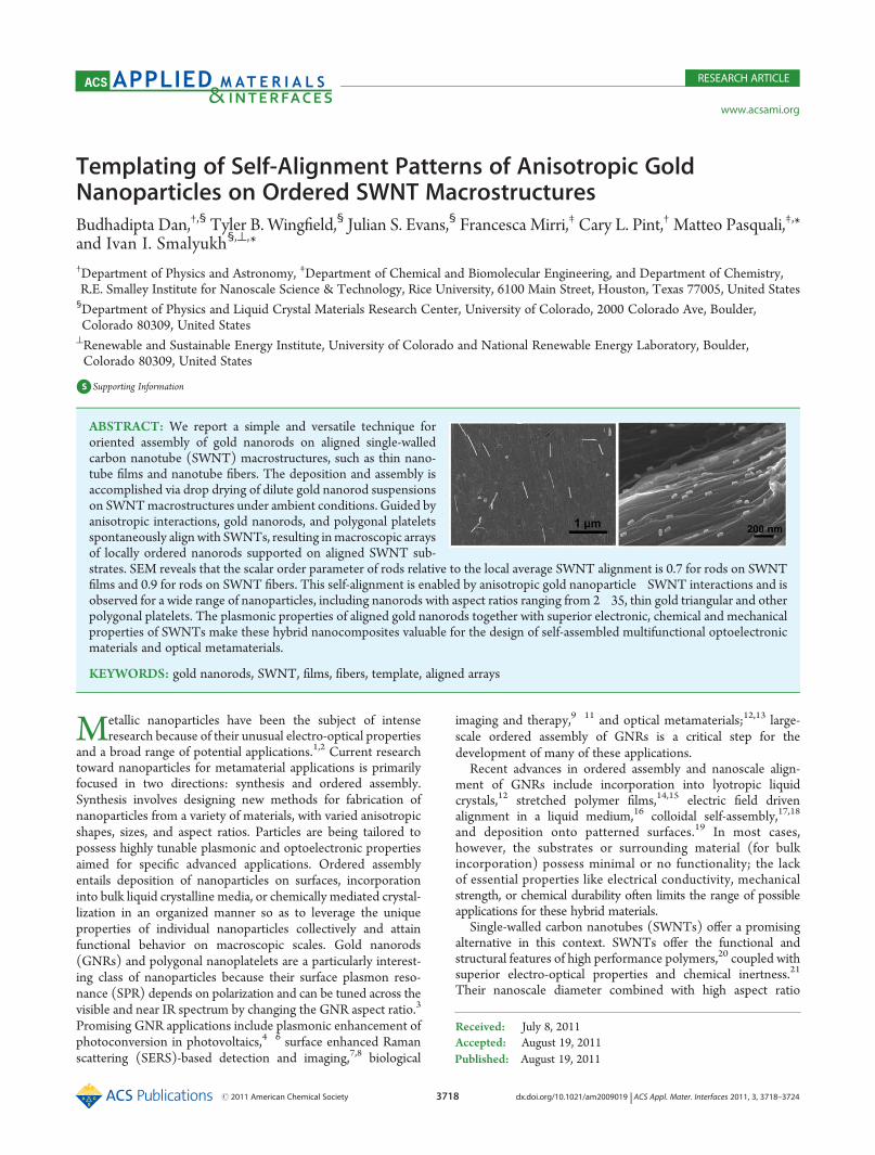
Figure 1. SEM of macroscopic ordered assemblies of gold nanorods (GNRs) of varying aspect ratios, produced by drop drying on aligned SWNT films.(a) Vertically aligned SWNT carpet. (b) Aligned SWNT film fabricated from SWNT carpet. (c) Spontaneous alignment of short GNRs (aspect ratio2�4) on SWNT film. (d) GNRs replicating the alignment defect in underlying film (shown with red arrows). (e, f) Alignment of medium (5�12) andlong (12�35) aspect ratio GNRs with SWNTs. Scale bars: (a) 15 μm, (b) 1 μm, (c) 400 nm, (d) 1 μm, (e) 500 nm, (f) 1 μm.
3720 dx.doi.org/10.1021/am2009019 |ACS Appl. Mater. Interfaces 2011, 3, 3718–3724
ACS Applied Materials & Interfaces RESEARCH ARTICLE
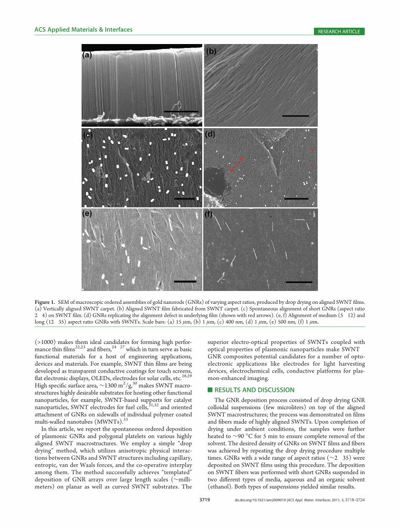
The GNR�SWNT composites were analyzed using SEMimaging. Remarkably, we found that a large fraction of GNRsspontaneously align along the SWNTs in the films and fibersduring the deposition process, as shown in Figure 1c�f andFigure 2b�c. In addition, the strong spontaneous alignment tothe SWNT substrate was observed for all GNR aspect ratios.Most of the nonaligned GNRs were within rare aggregates.Nonuniformities (cracks, sharp protrusions, misaligned domainsand domain boundaries, etc.) in the underlying SWNT macro-structure promoted aggregation and accumulation of GNRs,often leading to their nonuniform distribution. Employing diluteGNR suspensions limited the extent of GNR aggregationduring drop drying and yielded an ordered and oriented GNRdeposition.
Closer inspection of certain regions in GNR-SWNT thin filmswith imperfect alignment, like in Figure 1d, reveals that theGNRs closely follow the local SWNT alignment and thereforereproduce the defects and distortion patterns in their underlyingSWNTs. This shows the effectiveness of this technique as atemplating mechanism, which can be employed to replicatevaried and intricate patterns from underlying SWNT substratesto the deposited GNR layer. Because of the same effect, the GNRarrays deposited on the films and fibers shown in Figure 1 are lessordered on large length scales. In the films and fibers used here,SWNTs are aligned over large length scales (micrometers and
larger), but show considerable waviness and undulations atshorter length scales (tens of nanometers), that can be describedby a local direction of SWNT alignment, NSWNT(r). Betterunidirectional global alignment could be obtained by improvingthe alignment of the SWNTs and SWNT bundles in thesubstrates. An example of large area aligned GNR depositionon a well-aligned macroscopic SWNT fiber is shown in theSupporting Information (Figure S2).
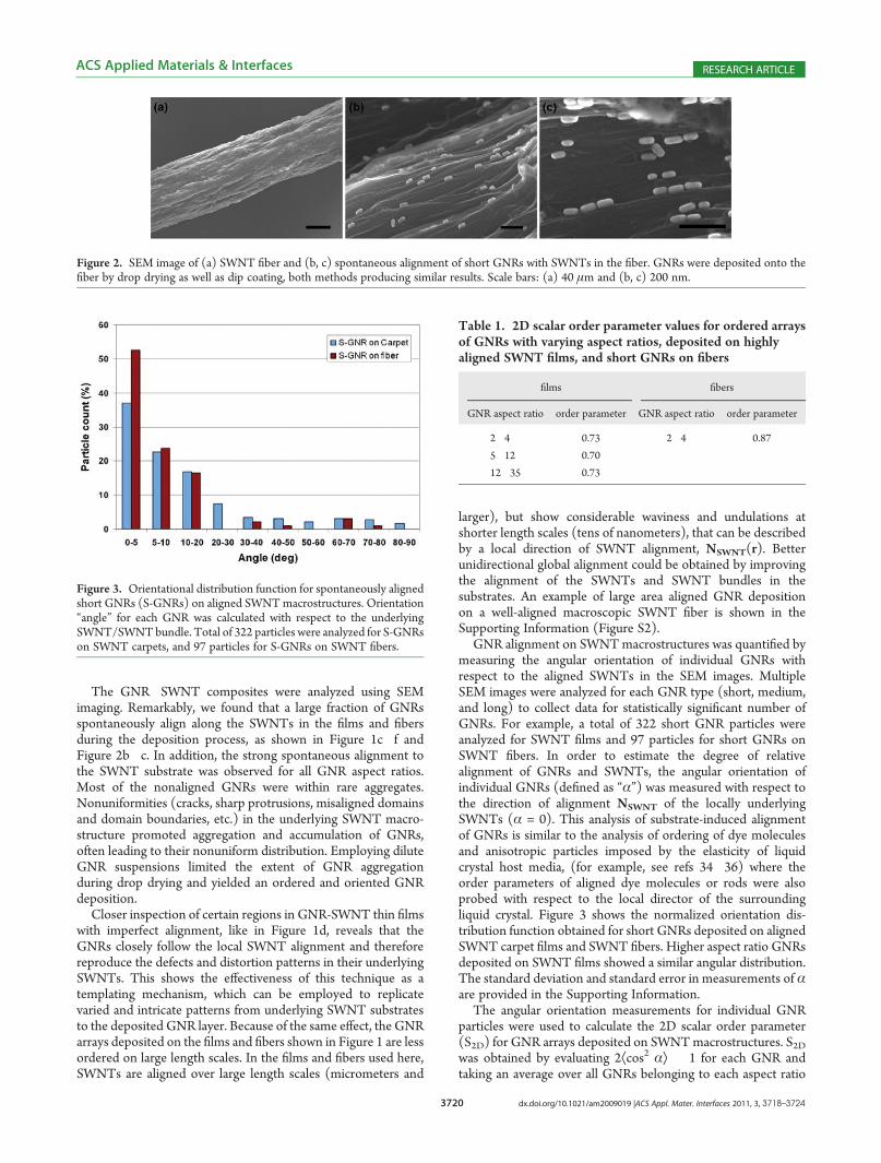
GNR alignment on SWNTmacrostructures was quantified bymeasuring the angular orientation of individual GNRs withrespect to the aligned SWNTs in the SEM images. MultipleSEM images were analyzed for each GNR type (short, medium,and long) to collect data for statistically significant number ofGNRs. For example, a total of 322 short GNR particles wereanalyzed for SWNT films and 97 particles for short GNRs onSWNT fibers. In order to estimate the degree of relativealignment of GNRs and SWNTs, the angular orientation ofindividual GNRs (defined as “α”) was measured with respect tothe direction of alignment NSWNT of the locally underlyingSWNTs (α = 0). This analysis of substrate-induced alignmentof GNRs is similar to the analysis of ordering of dye moleculesand anisotropic particles imposed by the elasticity of liquidcrystal host media, (for example, see refs 34�36) where theorder parameters of aligned dye molecules or rods were alsoprobed with respect to the local director of the surroundingliquid crystal. Figure 3 shows the normalized orientation dis-tribution function obtained for short GNRs deposited on alignedSWNT carpet films and SWNT fibers. Higher aspect ratio GNRsdeposited on SWNT films showed a similar angular distribution.The standard deviation and standard error in measurements of αare provided in the Supporting Information.
The angular orientation measurements for individual GNRparticles were used to calculate the 2D scalar order parameter(S2D) for GNR arrays deposited on SWNTmacrostructures. S2Dwas obtained by evaluating 2Æcos2 αæ � 1 for each GNR andtaking an average over all GNRs belonging to each aspect ratio
Figure 3. Orientational distribution function for spontaneously alignedshort GNRs (S-GNRs) on aligned SWNTmacrostructures. Orientation“angle” for each GNR was calculated with respect to the underlyingSWNT/SWNTbundle. Total of 322 particles were analyzed for S-GNRson SWNT carpets, and 97 particles for S-GNRs on SWNT fibers.
Table 1. 2D scalar order parameter values for ordered arraysof GNRs with varying aspect ratios, deposited on highlyaligned SWNT films, and short GNRs on fibers
films fibers
GNR aspect ratio order parameter GNR aspect ratio order parameter
2�4 0.73 2�4 0.87
5�12 0.70
12�35 0.73
Figure 2. SEM image of (a) SWNT fiber and (b, c) spontaneous alignment of short GNRs with SWNTs in the fiber. GNRs were deposited onto thefiber by drop drying as well as dip coating, both methods producing similar results. Scale bars: (a) 40 μm and (b, c) 200 nm.
3721 dx.doi.org/10.1021/am2009019 |ACS Appl. Mater. Interfaces 2011, 3, 3718–3724
ACS Applied Materials & Interfaces RESEARCH ARTICLE
group. S2D values obtained using this method of analysis “filterout” the effect of undulations imparted onto the GNR assemblybecaue of alignment imperfections in the SWNT substrate, andindicate the degree of ordering achievable in a GNR arraydeposited on a perfectly aligned SWNT substrate withNSWNT(r) =constant. The values of S2D listed in Table 1 further illustrate thehigh degree of spontaneous alignment amongGNRs, imposed bythe underlying ordered structures of SWNTs.
Interestingly, SWNT fibers produced better alignment and ahigher order parameter amongGNRs than the films. This is likelydue to the “grooved” surface morphology of the fibers (groovewidth ∼ tens of nanometers), which are composed of substruc-tures of smaller diameter SWNT ropes and fibrils. The unidirec-tional grooves which are comparable to the diameter of theGNRs but smaller than their length can exert entropic alignmentforces, leading to better alignment and higher order parameter.The alignment of GNRs on SWNT fibers demonstrates theportability of this technique to other SWNT macrostructures,including curved surfaces. Since the alignment behavior of GNRson SWNT films was independent of GNR aspect ratio, thedeposition on fibers was tested with only short GNRs.
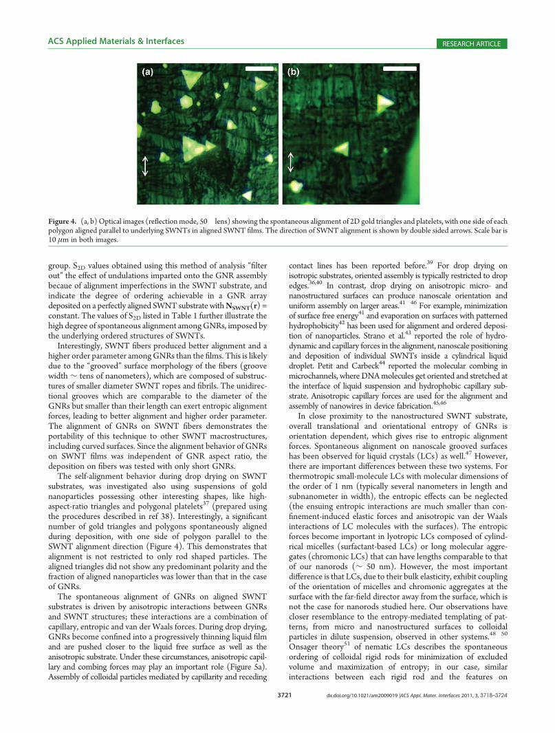
The self-alignment behavior during drop drying on SWNTsubstrates, was investigated also using suspensions of goldnanoparticles possessing other interesting shapes, like high-aspect-ratio triangles and polygonal platelets37 (prepared usingthe procedures described in ref 38). Interestingly, a significantnumber of gold triangles and polygons spontaneously alignedduring deposition, with one side of polygon parallel to theSWNT alignment direction (Figure 4). This demonstrates thatalignment is not restricted to only rod shaped particles. Thealigned triangles did not show any predominant polarity and thefraction of aligned nanoparticles was lower than that in the caseof GNRs.
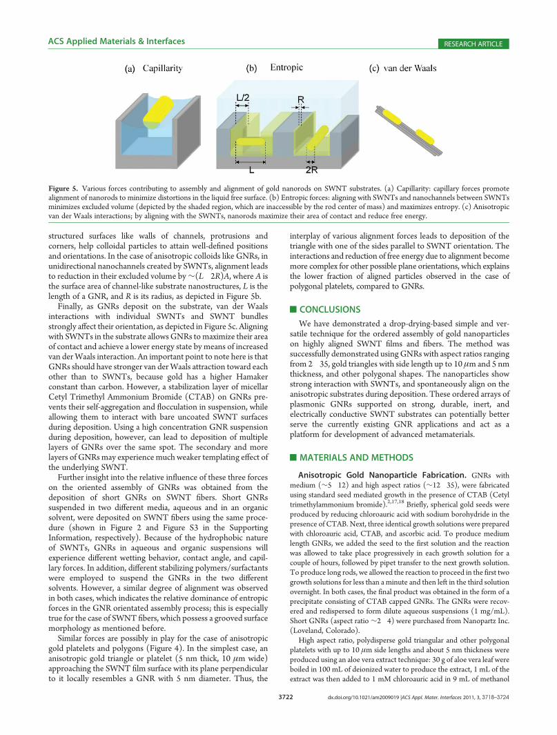
The spontaneous alignment of GNRs on aligned SWNTsubstrates is driven by anisotropic interactions between GNRsand SWNT structures; these interactions are a combination ofcapillary, entropic and van der Waals forces. During drop drying,GNRs become confined into a progressively thinning liquid filmand are pushed closer to the liquid free surface as well as theanisotropic substrate. Under these circumstances, anisotropic capil-lary and combing forces may play an important role (Figure 5a).Assembly of colloidal particles mediated by capillarity and receding
contact lines has been reported before.39 For drop drying onisotropic substrates, oriented assembly is typically restricted to dropedges.36,40 In contrast, drop drying on anisotropic micro- andnanostructured surfaces can produce nanoscale orientation anduniform assembly on larger areas.41�46 For example, minimizationof surface free energy41 and evaporation on surfaces with patternedhydrophobicity42 has been used for alignment and ordered deposi-tion of nanoparticles. Strano et al.43 reported the role of hydro-dynamic and capillary forces in the alignment, nanoscale positioningand deposition of individual SWNTs inside a cylindrical liquiddroplet. Petit and Carbeck44 reported the molecular combing inmicrochannels, where DNAmolecules get oriented and stretched atthe interface of liquid suspension and hydrophobic capillary sub-strate. Anisotropic capillary forces are used for the alignment andassembly of nanowires in device fabrication.45,46
In close proximity to the nanostructured SWNT substrate,overall translational and orientational entropy of GNRs isorientation dependent, which gives rise to entropic alignmentforces. Spontaneous alignment on nanoscale grooved surfaceshas been observed for liquid crystals (LCs) as well.47 However,there are important differences between these two systems. Forthermotropic small-molecule LCs with molecular dimensions ofthe order of 1 nm (typically several nanometers in length andsubnanometer in width), the entropic effects can be neglected(the ensuing entropic interactions are much smaller than con-finement-induced elastic forces and anisotropic van der Waalsinteractions of LC molecules with the surfaces). The entropicforces become important in lyotropic LCs composed of cylind-rical micelles (surfactant-based LCs) or long molecular aggre-gates (chromonic LCs) that can have lengths comparable to thatof our nanorods (∼ 50 nm). However, the most importantdifference is that LCs, due to their bulk elasticity, exhibit couplingof the orientation of micelles and chromonic aggregates at thesurface with the far-field director away from the surface, which isnot the case for nanorods studied here. Our observations havecloser resemblance to the entropy-mediated templating of pat-terns, from micro and nanostructured surfaces to colloidalparticles in dilute suspension, observed in other systems.48�50
Onsager theory51 of nematic LCs describes the spontaneousordering of colloidal rigid rods for minimization of excludedvolume and maximization of entropy; in our case, similarinteractions between each rigid rod and the features on
Figure 4. (a, b) Optical images (reflectionmode, 50� lens) showing the spontaneous alignment of 2D gold triangles and platelets, with one side of eachpolygon aligned parallel to underlying SWNTs in aligned SWNT films. The direction of SWNT alignment is shown by double sided arrows. Scale bar is10 μm in both images.
3722 dx.doi.org/10.1021/am2009019 |ACS Appl. Mater. Interfaces 2011, 3, 3718–3724
ACS Applied Materials & Interfaces RESEARCH ARTICLE
structured surfaces like walls of channels, protrusions andcorners, help colloidal particles to attain well-defined positionsand orientations. In the case of anisotropic colloids like GNRs, inunidirectional nanochannels created by SWNTs, alignment leadsto reduction in their excluded volume by∼(L�2R)A, where A isthe surface area of channel-like substrate nanostructures, L is thelength of a GNR, and R is its radius, as depicted in Figure 5b.
Finally, as GNRs deposit on the substrate, van der Waalsinteractions with individual SWNTs and SWNT bundlesstrongly affect their orientation, as depicted in Figure 5c. Aligningwith SWNTs in the substrate allowsGNRs tomaximize their areaof contact and achieve a lower energy state by means of increasedvan derWaals interaction. An important point to note here is thatGNRs should have stronger van derWaals attraction toward eachother than to SWNTs, because gold has a higher Hamakerconstant than carbon. However, a stabilization layer of micellarCetyl Trimethyl Ammonium Bromide (CTAB) on GNRs pre-vents their self-aggregation and flocculation in suspension, whileallowing them to interact with bare uncoated SWNT surfacesduring deposition. Using a high concentration GNR suspensionduring deposition, however, can lead to deposition of multiplelayers of GNRs over the same spot. The secondary and morelayers of GNRsmay experience much weaker templating effect ofthe underlying SWNT.
Further insight into the relative influence of these three forceson the oriented assembly of GNRs was obtained from thedeposition of short GNRs on SWNT fibers. Short GNRssuspended in two different media, aqueous and in an organicsolvent, were deposited on SWNT fibers using the same proce-dure (shown in Figure 2 and Figure S3 in the SupportingInformation, respectively). Because of the hydrophobic natureof SWNTs, GNRs in aqueous and organic suspensions willexperience different wetting behavior, contact angle, and capil-lary forces. In addition, different stabilizing polymers/surfactantswere employed to suspend the GNRs in the two differentsolvents. However, a similar degree of alignment was observedin both cases, which indicates the relative dominance of entropicforces in the GNR orientated assembly process; this is especiallytrue for the case of SWNT fibers, which possess a grooved surfacemorphology as mentioned before.
Similar forces are possibly in play for the case of anisotropicgold platelets and polygons (Figure 4). In the simplest case, ananisotropic gold triangle or platelet (5 nm thick, 10 μm wide)approaching the SWNT film surface with its plane perpendicularto it locally resembles a GNR with 5 nm diameter. Thus, the
interplay of various alignment forces leads to deposition of thetriangle with one of the sides parallel to SWNT orientation. Theinteractions and reduction of free energy due to alignment becomemore complex for other possible plane orientations, which explainsthe lower fraction of aligned particles observed in the case ofpolygonal platelets, compared to GNRs.
’CONCLUSIONS
We have demonstrated a drop-drying-based simple and ver-satile technique for the ordered assembly of gold nanoparticleson highly aligned SWNT films and fibers. The method wassuccessfully demonstrated usingGNRs with aspect ratios rangingfrom 2�35, gold triangles with side length up to 10 μm and 5 nmthickness, and other polygonal shapes. The nanoparticles showstrong interaction with SWNTs, and spontaneously align on theanisotropic substrates during deposition. These ordered arrays ofplasmonic GNRs supported on strong, durable, inert, andelectrically conductive SWNT substrates can potentially betterserve the currently existing GNR applications and act as aplatform for development of advanced metamaterials.
’MATERIALS AND METHODS
Anisotropic Gold Nanoparticle Fabrication. GNRs withmedium (∼5�12) and high aspect ratios (∼12�35), were fabricatedusing standard seed mediated growth in the presence of CTAB (Cetyltrimethylammonium bromide).2,17,18 Briefly, spherical gold seeds wereproduced by reducing chloroauric acid with sodium borohydride in thepresence of CTAB. Next, three identical growth solutions were preparedwith chloroauric acid, CTAB, and ascorbic acid. To produce mediumlength GNRs, we added the seed to the first solution and the reactionwas allowed to take place progressively in each growth solution for acouple of hours, followed by pipet transfer to the next growth solution.To produce long rods, we allowed the reaction to proceed in the first twogrowth solutions for less than a minute and then left in the third solutionovernight. In both cases, the final product was obtained in the form of aprecipitate consisting of CTAB capped GNRs. The GNRs were recov-ered and redispersed to form dilute aqueous suspensions (1 mg/mL).Short GNRs (aspect ratio ∼2�4) were purchased from Nanopartz Inc.(Loveland, Colorado).
High aspect ratio, polydisperse gold triangular and other polygonalplatelets with up to 10 μm side lengths and about 5 nm thickness wereproduced using an aloe vera extract technique: 30 g of aloe vera leaf wereboiled in 100 mL of deionized water to produce the extract, 1 mL of theextract was then added to 1 mM chloroauric acid in 9 mL of methanol
Figure 5. Various forces contributing to assembly and alignment of gold nanorods on SWNT substrates. (a) Capillarity: capillary forces promotealignment of nanorods to minimize distortions in the liquid free surface. (b) Entropic forces: aligning with SWNTs and nanochannels between SWNTsminimizes excluded volume (depicted by the shaded region, which are inaccessible by the rod center of mass) and maximizes entropy. (c) Anisotropicvan der Waals interactions; by aligning with the SWNTs, nanorods maximize their area of contact and reduce free energy.
3723 dx.doi.org/10.1021/am2009019 |ACS Appl. Mater. Interfaces 2011, 3, 3718–3724
ACS Applied Materials & Interfaces RESEARCH ARTICLE
and allowed to sit at room temperature for several days (for more detailssee refs 38 and 52).Aligned SWNT Macrostructure Fabrication. Thin films of
horizontally aligned SWNTs were prepared from vertically alignedSWNT “carpets” produced using the method described by Xu et al.53
The carpets typically consisted of 20�200 μm long vertical array ofSWNTs bound to Fe catalyst particles and supported on Siliconsubstrates, as shown in Figure 1a. Thin films were obtained from theSWNT carpets using a modified version of the “roll-over” method.54 Inshort, vertically aligned SWNTs were “tilted” toward the desireddirection of alignment by gentle unidirectional rubbing with a cleanstrip of velvet cloth, followed by the “rolling” process which compressesthe carpet into a dense, highly aligned SWNT film (Figure 1b). A thinsheet of aluminum foil was used during rolling to prevent transfer of anySWNTs from the carpet on to the roller. Dipping these SWNT films in1 M HCl solution etches away the catalyst particles, resulting in theirimmediate detachment from Silicon substrates; the free floating filmscan then be transferred onto any desired substrate.
SWNT fibers were produced by wet spinning from high concentra-tion (>8 wt %) SWNT-Oleum (100% sulfuric acid + 20% SO3)solutions.25,55�58 Polarized Raman spectroscopy of the fiber showedthat for the so-called G peak (∼1591 cm�1) the ratio of intensitiesmeasured for polarizations in longitudinal vs transverse directions isabout 2.4, indicating a high degree of SWNT alignment, furtherconfirmed by SEM (Figure 2a). SEM was performed using a (JEOLJSM-7401F FESEM).
’ASSOCIATED CONTENT
bS Supporting Information. Order parameter calculation,typical error in measurements, and SEM images of single andmultiple rounds of GNR deposition on SWNT film and fibers.This material is available free of charge via the Internet at http://pubs.acs.org/.
’AUTHOR INFORMATION
Corresponding Author*E-mail: [email protected] (M.P.); [email protected] (I.I.S.).
’ACKNOWLEDGMENT
The authors thank Natnael Behabtu, Colin Young, and DmitriTsentalovich for providing SWNT fiber samples; and DennisGardner, Angel Martinez, and Sabrina Thompson for helpfuldiscussions and technical assistance at different stages of thisproject. We acknowledge support of the Institute for ComplexAdaptive Matter, Colorado Renewable and Sustainable EnergyInitiative, NSF Grants DMR-0820579, DMR-0844115, andDMR-0847782, Air Force Research Lab Grant FA 8650-07-2-5061 (managed by CONTACT), Air Force Office of ScientificResearch grant FA9550-09-1-0590, Welch Grant C-1668, andU.S. Army Corps of Engineers Environmental Quality andInstallation Program under Grant W912HZ-08-C-0054.
’REFERENCES
(1) Daniel, M. C.; Astruc, D. Chem. Rev. 2004, 104 (1), 293–346.(2) Murphy, C. J.; San, T. K.; Gole, A.M.; Orendorff, C. J.; Gao, J. X.;
Gou, L.; Hunyadi, S. E.; Li, T. J. Phys. Chem. B 2005, 109 (29),13857–13870.(3) Link, S.; Mohamed, M. B.; El-Sayed, M. A. J. Phys. Chem. B 1999,
103 (16), 3073–3077.
(4) Westphalen, M.; Kreibig, U.; Rostalski, J.; Luth, H.; Meissner, D.Sol. Energy Mater. Sol. Cells 2000, 61 (1), 97–105.
(5) Atwater, H. A.; Polman, A. Nat. Mater. 2010, 9 (3), 205–213.(6) Morfa, A. J.; Rowlen, K. L.; Reilly, T. H.; Romero, M. J.; van de
Lagemaat, J. Appl. Phys. Lett. 2008, 92 (1), 013504.(7) Orendorff, C. J.; Gearheart, L.; Jana, N. R.; Murphy, C. J. Phys.
Chem. Chem. Phys. 2006, 8 (1), 165–170.(8) Nikoobakht, B.; El-Sayed, M. A. J. Phys. Chem. A 2003, 107 (18),
3372–3378.(9) Huang, X. H.; El-Sayed, I. H.; Qian, W.; El-Sayed, M. A. J. Am.
Chem. Soc. 2006, 128 (6), 2115–2120.(10) Huang, X. H.; El-Sayed, I. H.; Qian, W.; El-Sayed, M. A. Nano
Lett. 2007, 7 (6), 1591–1597.(11) Durr, N. J.; Larson, T.; Smith, D. K.; Korgel, B. A.; Sokolov, K.;
Ben-Yakar, A. Nano Lett. 2007, 7 (4), 941–945.(12) Liu, Q. K.; Cui, Y. X.; Gardner, D.; Li, X.; He, S. L.; Smalyukh, I.
Nano Lett. 2010, 10 (4), 1347–1353.(13) Shalaev, V. M.; Cai, W. S.; Chettiar, U. K.; Yuan, H. K.;
Sarychev, A. K.; Drachev, V. P.; Kildishev, A. V. Opt. Lett. 2005, 30(24), 3356–3358.
(14) Shenhar, R.; Norsten, T. B.; Rotello, V. M. Adv. Mater. 2005, 17(6), 657–669.
(15) Murphy, C. L.; Orendorff, C. J. Adv. Mater. 2005, 17 (18),2173–2177.
(16) van der Zande, B. M. I.; Koper, G. J. M.; Lekkerkerker, H. N.W.J. Phys. Chem. B 1999, 103 (28), 5754–5760.
(17) Jana, N. R.; Gearheart, L. A.; Obare, S. O.; Johnson, C. J.; Edler,K. J.; Mann, S.; Murphy, C. J. J. Mater. Chem. 2002, 12 (10), 2909–2912.
(18) Nikoobakht, B.; Wang, Z. L.; El-Sayed, M. A. J. Phys. Chem. B2000, 104 (36), 8635–8640.
(19) Liu, S. H.; Tok, J. B. H.; Locklin, J.; Bao, Z. N. Small 2006, 2(12), 1448–1453.
(20) Green, M. J.; Behabtu, N.; Pasquali, M.; Adams, W. W. Polymer2009, 50 (21), 4979–4997.
(21) Tans, S. J.; Devoret, M. H.; Dai, H. J.; Thess, A.; Smalley, R. E.;Geerligs, L. J.; Dekker, C. Nature 1997, 386 (6624), 474–477.
(22) Dan, B.; Irvin, G. C.; Pasquali, M. ACS Nano 2009, 3 (4),835–843.
(23) Wu, Z. C.; Chen, Z. H.; Du, X.; Logan, J. M.; Sippel, J.; Nikolou,M.; Kamaras, K.; Reynolds, J. R.; Tanner, D. B.; Hebard, A. F.; Rinzler,A. G. Science 2004, 305 (5688), 1273–1276.
(24) Behabtu, N.; Green, M. J.; Pasquali, M. Nano Today 2008, 3(5�6), 24–34.
(25) Davis, V. A.; Parra-Vasquez, A. N. G.; Green, M. J.; Rai, P. K.;Behabtu, N.; Prieto, V.; Booker, R. D.; Schmidt, J.; Kesselman, E.; Zhou,W.; Fan, H.; Adams, W. W.; Hauge, R. H.; Fischer, J. E.; Cohen, Y.;Talmon, Y.; Smalley, R. E.; Pasquali, M. Nat. Nanotechnol. 2009, 4 (12),830–834.
(26) Li, Y. L.; Kinloch, I. A.; Windle, A. H. Science 2004, 304 (5668),276–278.
(27) Miaudet, P.; Badaire, S.; Maugey, M.; Derre, A.; Pichot, V.;Launois, P.; Poulin, P.; Zakri, C. Nano Lett. 2005, 5 (11), 2212–2215.
(28) Hu, L.; Hecht, D. S.; Gruner, G. Chem. Rev. 2010, 110 (10),5790–844.
(29) Kong, B. S.; Jung, D. H.; Oh, S. K.; Han, C. S.; Jung, H. T.J. Phys. Chem. C 2007, 111 (23), 8377–8382.(30) Peigney, A.; Laurent, C.; Flahaut, E.; Bacsa, R. R.; Rousset, A.
Carbon 2001, 39 (4), 507–514.(31) Girishkumar, G.; Vinodgopal, K.; Kamat, P. V. J.Phys. Chem. B
2004, 108 (52), 19960–19966.(32) Planeix, J.M.; Coustel, N.; Coq, B.; Brotons, V.; Kumbhar, P. S.;
Dutartre, R.; Geneste, P.; Bernier, P.; Ajayan, P. M. J. Am. Chem. Soc.1994, 116 (17), 7935–7936.
(33) Correa-Duarte, M. A.; Perez-Juste, J.; Sanchez-Iglesias, A.;Giersig, M.; Liz-Marzan, L. M. Angew. Chem.,Int. Ed. 2005, 44 (28),4375–4378.
(34) Yang, D.-K.; Wu, S.-T., Fundamentals of Liquid Crystal Devices;John Wiley: Hoboken, NJ, 2006.
3724 dx.doi.org/10.1021/am2009019 |ACS Appl. Mater. Interfaces 2011, 3, 3718–3724
ACS Applied Materials & Interfaces RESEARCH ARTICLE
(35) Collings, P. J.; Ratna, B. R.; Shashidhar, R. Phys. Rev. E 2003, 67(2), 21705.(36) Smalyukh, I. I.; Butler, J.; Shrout, J. D.; Parsek, M. R.; Wong,
G. C. L. Phys. Rev. E 2008, 78 (3), 30701.(37) Lapointe, C. P.; Mason, T. G.; Smalyukh, I. I. Science 2009, 326
(5956), 1083–1086.(38) Evans, J. S.; Beier, C.; Smalyukh, I. I. J. Appl. Phys. 2011, 110,
033535.(39) Deegan, R. D.; Bakajin, O.; Dupont, T. F.; Huber, G.; Nagel,
S. R.; Witten, T. A. Nature 1997, 389 (6653), 827–829.(40) Li, Q.W.; Zhu, Y. T.; Kinloch, I. A.; Windle, A. H. J. Phys. Chem.
B 2006, 110 (28), 13926–13930.(41) Lewandowski, E. P.; Bernate, J. A.; Searson, P. C.; Stebe, K. J.
Langmuir 2008, 24 (17), 9302–9307.(42) Fan, F. Q.; Stebe, K. J. Langmuir 2004, 20 (8), 3062–3067.(43) Sharma, R.; Lee, C. Y.; Choi, J. H.; Chen, K.; Strano, M. S.Nano
Lett. 2007, 7 (9), 2693–2700.(44) Petit, C. A. P.; Carbeck, J. D. Nano Lett. 2003, 3 (8),
1141–1146.(45) Messer, B.; Song, J. H.; Yang, P. D. J. Am. Chem. Soc. 2000, 122
(41), 10232–10233.(46) Salalha, W.; Zussman, E. Phys. Fluids 2005, 17 (6), 063301.(47) Berreman, D. W. Phys. Rev. Lett. 1972, 28 (26), 1683–1686.(48) Dinsmore, A. D.; Yodh, A. G.; Pine, D. J. Nature 1996, 383
(6597), 239–242.(49) Gupta, S.; Zhang, Q. L.; Emrick, T.; Balazs, A. C.; Russell, T. P.
Nat. Mater. 2006, 5 (3), 229–233.(50) Yodh, A. G.; Lin, K. H.; Crocker, J. C.; Dinsmore, A. D.; Verma,
R.; Kaplan, P. D. Philos. T.rans. R. Soc. Chem., Ser. A 2001, 359 (1782),921–937.(51) Onsager, L. Ann. N.Y. Acad. Sci. 1949, 51 (4), 627–659.(52) Chandran, S. P.; Chaudhary, M.; Pasricha, R.; Ahmad, A.;
Sastry, M. Biotechnol. Prog. 2006, 22 (2), 577–583.(53) Xu, Y. Q.; Flor, E.; Kim, M. J.; Hamadani, B.; Schmidt, H.;
Smalley, R. E.; Hauge, R. H. J. Am. Chem. Soc. 2006, 128 (20),6560–6561.(54) Pint, C. L.; Xu, Y. Q.; Pasquali, M.; Hauge, R. H. ACS Nano
2008, 2 (9), 1871–1878.(55) Ericson, L. M.; Fan, H.; Peng, H. Q.; Davis, V. A.; Zhou, W.;
Sulpizio, J.;Wang, Y. H.; Booker, R.; Vavro, J.; Guthy, C.; Parra-Vasquez,A. N. G.; Kim, M. J.; Ramesh, S.; Saini, R. K.; Kittrell, C.; Lavin, G.;Schmidt, H.; Adams, W. W.; Billups, W. E.; Pasquali, M.; Hwang, W. F.;Hauge, R. H.; Fischer, J. E.; Smalley, R. E. Science 2004, 305 (5689),1447–1450.(56) Wang, Y.; Ericson, L. M.; Kittrell, C.; Kim, M. J.; Shan, H.; Fan,
H.; Ripley, S.; Ramesh, S.; Hauge, R. H.; Adams, W. W.; Pasquali, M.;Smalley, R. E. Chem. Mater. 2005, 17 (25), 6361–6368.(57) Booker, R.; Green, M.; Fan, H.; Parra-Vasquez, A.; Behabtu, N.;
Young, C.; Hauge, R.; Schmidt, H.; Smalley, R.; Hwang,W.; Pasquali, M.Proc. Inst.Mech. Eng., Part N: J. Nanoeng. Nanosyst. 2008, 222 (3),101–109.(58) Davis, V. A.; Ericson, L. M.; Parra-Vasquez, A. N. G.; Fan, H.;
Wang, Y. H.; Prieto, V.; Longoria, J. A.; Ramesh, S.; Saini, R. K.; Kittrell,C.; Billups, W. E.; Adams, W. W.; Hauge, R. H.; Smalley, R. E.; Pasquali,M. Macromolecules 2004, 37 (1), 154–160.