telos mote datasheet
TRANSCRIPT
Telos
Rev B (Low Power Wireless Sensor Module)
Moteiv Corporation Telos (Rev B) : PRELIMINARY Datasheet (12/5/2004) Page 1 of 28
Telos Ultra low power IEEE 802.15.4 compliant wireless sensor module Revision B : Humidity, Light, and Temperature sensors with USB
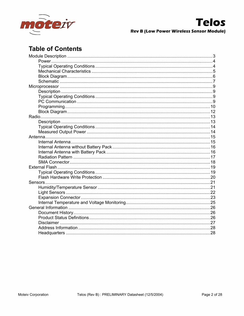
Product Description Telos is an ultra low power wireless module for use in sensor networks, monitoring applications, and rapid application prototyping. Telos leverages industry standards like USB and IEEE 802.15.4 to interoperate seamlessly with other devices. By using industry standards, integrating humidity, temperature, and light sensors, and providing flexible interconnection with peripherals, Telos enables a wide range of mesh network applications. Telos Revision B is a drop-in replacement for Moteiv’s successful Revision A design. Revision B includes increased performance, functionality, and expansion. With TinyOS support out-of-the-box, Telos leverages emerging wireless protocols and the open source software movement. Telos is part of a line of modules featuring on-board sensors to increase robustness while decreasing cost and package size.
Key Features • 250kbps 2.4GHz IEEE 802.15.4 Chipcon Wireless Transceiver • Interoperability with other IEEE 802.15.4 devices • 8MHz Texas Instruments MSP430 microcontroller (10k RAM, 48k Flash) • Integrated ADC, DAC, Supply Voltage Supervisor, and DMA Controller • Integrated onboard antenna with 50m range indoors / 125m range outdoors • Integrated Humidity, Temperature, and Light sensors • Ultra low current consumption • Fast wakeup from sleep (<6µs) • Hardware link-layer encryption and authentication • Programming and data collection via USB • 16-pin expansion support and optional SMA antenna connector • TinyOS support : mesh networking and communication implementation
Telos
Rev B (Low Power Wireless Sensor Module)
Moteiv Corporation Telos (Rev B) : PRELIMINARY Datasheet (12/5/2004) Page 2 of 28
Table of Contents Module Description .......................................................................................................................3
Power ....................................................................................................................................4 Typical Operating Conditions ................................................................................................4 Mechanical Characteristics ...................................................................................................5 Block Diagram.......................................................................................................................6 Schematic .............................................................................................................................7
Microprocessor .............................................................................................................................9 Description ............................................................................................................................9 Typical Operating Conditions ................................................................................................9 PC Communication ...............................................................................................................9 Programming.......................................................................................................................10 Block Diagram.....................................................................................................................12
Radio...........................................................................................................................................13 Description ..........................................................................................................................13 Typical Operating Conditions ..............................................................................................14 Measured Output Power .....................................................................................................14
Antenna.......................................................................................................................................15 Internal Antenna..................................................................................................................15 Internal Antenna without Battery Pack ................................................................................16 Internal Antenna with Battery Pack .....................................................................................16 Radiation Pattern ................................................................................................................17 SMA Connector...................................................................................................................18
External Flash .............................................................................................................................19 Typical Operating Conditions ..............................................................................................19 Flash Hardware Write Protection ........................................................................................20
Sensors.......................................................................................................................................21 Humidity/Temperature Sensor ............................................................................................21 Light Sensors ......................................................................................................................22 Expansion Connector..........................................................................................................23 Internal Temperature and Voltage Monitoring.....................................................................25
General Information ....................................................................................................................26 Document History................................................................................................................26 Product Status Definitions...................................................................................................26 Disclaimer ...........................................................................................................................27 Address Information ............................................................................................................28 Headquarters ......................................................................................................................28
Telos
Rev B (Low Power Wireless Sensor Module)
Moteiv Corporation Telos (Rev B) : PRELIMINARY Datasheet (12/5/2004) Page 3 of 28
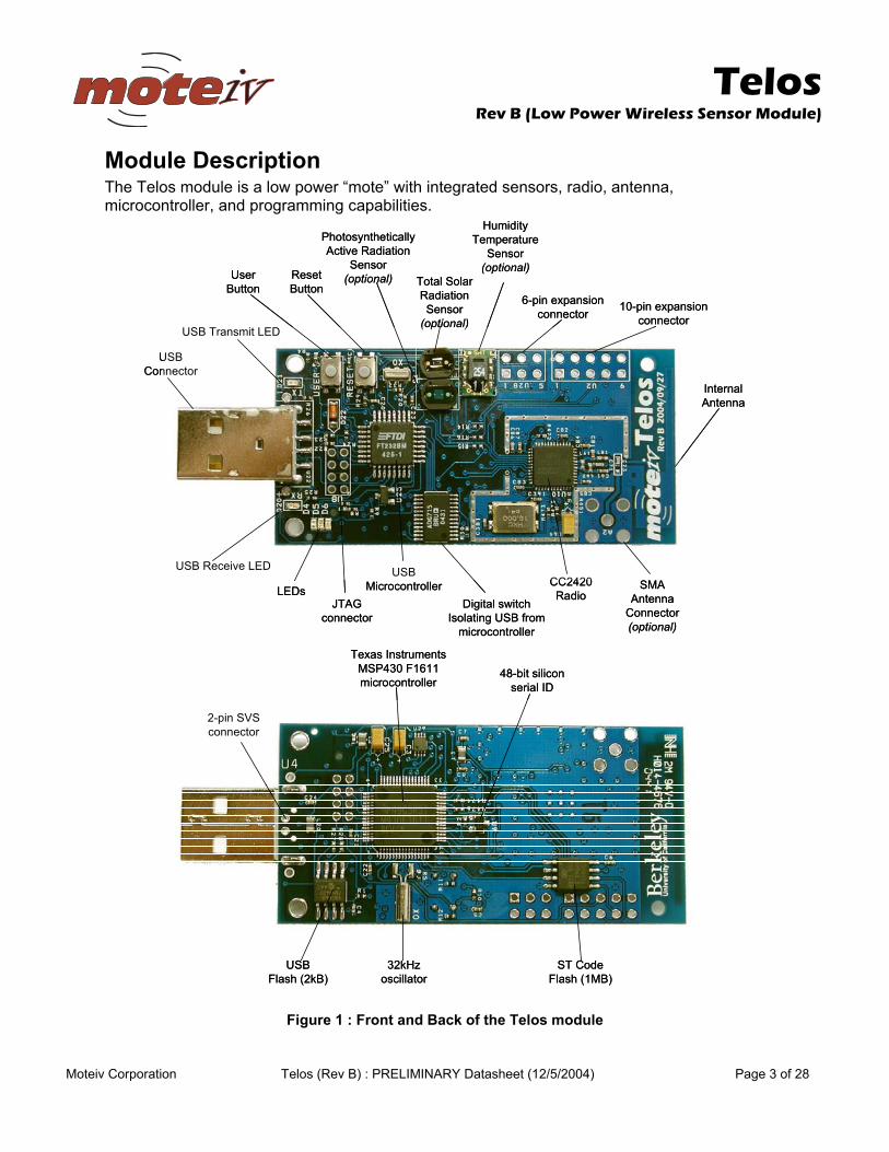
Module Description The Telos module is a low power “mote” with integrated sensors, radio, antenna, microcontroller, and programming capabilities.
USBConnector
UserButton
ResetButton
PhotosyntheticallyActive Radiation
Sensor(optional) Total Solar
RadiationSensor(optional)
10-pin expansionconnector
6-pin expansionconnector
InternalAntenna
CC2420Radio
SMAAntenna
Connector(optional)
HumidityTemperature
Sensor(optional)
USB Transmit LED
USB Receive LED
LEDsUSB
MicrocontrollerDigital switch
Isolating USB frommicrocontroller
JTAGconnector
USBFlash (2kB)
ST CodeFlash (1MB)
Texas InstrumentsMSP430 F1611microcontroller
32kHzoscillator
48-bit siliconserial ID
2-pin SVSconnector
USBFlash (2kB)
ST CodeFlash (1MB)
Texas InstrumentsMSP430 F1611microcontroller
32kHzoscillator
48-bit siliconserial ID
2-pin SVSconnector
Figure 1 : Front and Back of the Telos module
Telos
Rev B (Low Power Wireless Sensor Module)
Moteiv Corporation Telos (Rev B) : PRELIMINARY Datasheet (12/5/2004) Page 4 of 28
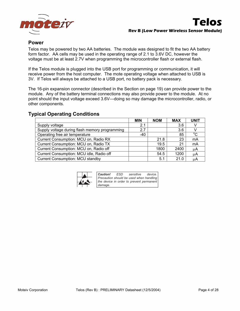
Power Telos may be powered by two AA batteries. The module was designed to fit the two AA battery form factor. AA cells may be used in the operating range of 2.1 to 3.6V DC, however the voltage must be at least 2.7V when programming the microcontroller flash or external flash. If the Telos module is plugged into the USB port for programming or communication, it will receive power from the host computer. The mote operating voltage when attached to USB is 3V. If Telos will always be attached to a USB port, no battery pack is necessary. The 16-pin expansion connector (described in the Section on page 19) can provide power to the module. Any of the battery terminal connections may also provide power to the module. At no point should the input voltage exceed 3.6V—doing so may damage the microcontroller, radio, or other components.
Typical Operating Conditions MIN NOM MAX UNIT Supply voltage 2.1 3.6 V Supply voltage during flash memory programming 2.7 3.6 V Operating free air temperature -40 85 oC Current Consumption: MCU on, Radio RX 21.8 23 mA Current Consumption: MCU on, Radio TX 19.5 21 mA Current Consumption: MCU on, Radio off 1800 2400 µA Current Consumption: MCU idle, Radio off 54.5 1200 µA Current Consumption: MCU standby 5.1 21.0 µA
Caution! ESD sensitive device. Precaution should be used when handling the device in order to prevent permanent damage.
Telos
Rev B (Low Power Wireless Sensor Module)
Moteiv Corporation Telos (Rev B) : PRELIMINARY Datasheet (12/5/2004) Page 5 of 28
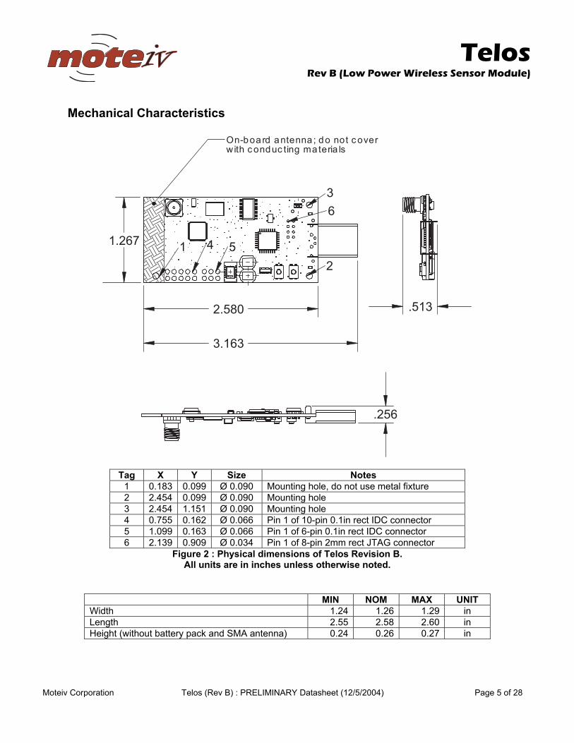
Mechanical Characteristics
revoc ton od ;annetna draob-nO
1 4 5
6
2
3
slairetam gnitcudnoc htiw
361.3
085.2
762.1
652.
315.
Tag X Y Size Notes 1 0.183 0.099 Ø 0.090 Mounting hole, do not use metal fixture 2 2.454 0.099 Ø 0.090 Mounting hole 3 2.454 1.151 Ø 0.090 Mounting hole 4 0.755 0.162 Ø 0.066 Pin 1 of 10-pin 0.1in rect IDC connector 5 1.099 0.163 Ø 0.066 Pin 1 of 6-pin 0.1in rect IDC connector 6 2.139 0.909 Ø 0.034 Pin 1 of 8-pin 2mm rect JTAG connector
Figure 2 : Physical dimensions of Telos Revision B. All units are in inches unless otherwise noted.
MIN NOM MAX UNIT Width 1.24 1.26 1.29 in Length 2.55 2.58 2.60 in Height (without battery pack and SMA antenna) 0.24 0.26 0.27 in
Telos
Rev B (Low Power Wireless Sensor Module)
Moteiv Corporation Telos (Rev B) : PRELIMINARY Datasheet (12/5/2004) Page 6 of 28
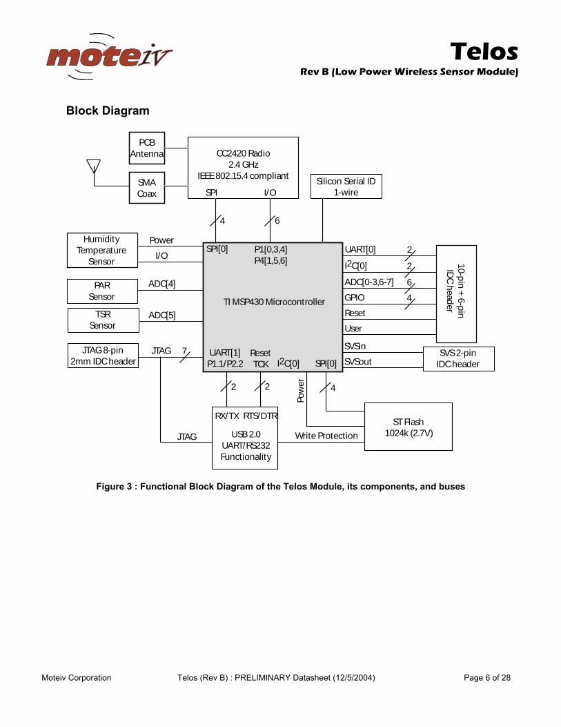
Block Diagram
CC2420 Radio2.4 GHz
IEEE 802.15.4 compliant
PCBAntenna
SMACoax
4
2
6
2
2UART[0]
2I2C[0]
6ADC[0-3,6-7]
4GPIO
HumidityTemperature
Sensor
PARSensor
TSRSensor
ADC[4]
ADC[5]
I/O
Power
SPI I/O
4
Pow
erReset
User
10-pin
+ 6-p
inID
C h
eader
SVSin
SVSout
TI MSP430 Microcontroller
UART[1]P1.1/P2.2
ResetTCK
SPI[0] P1[0,3,4]P4[1,5,6]
SPI[0]I2C[0]
Silicon Serial ID1-wire
7JTAGJTAG 8-pin2mm IDC header
SVS 2-pinIDC header
USB 2.0UART/RS232Functionality
RX/TX RTS/DTR
JTAG Write Protection
ST Flash1024k (2.7V)
Figure 3 : Functional Block Diagram of the Telos Module, its components, and buses
Telos
Rev B (Low Power Wireless Sensor Module)
Moteiv Corporation Telos (Rev B) : PRELIMINARY Datasheet (12/5/2004) Page 7 of 28
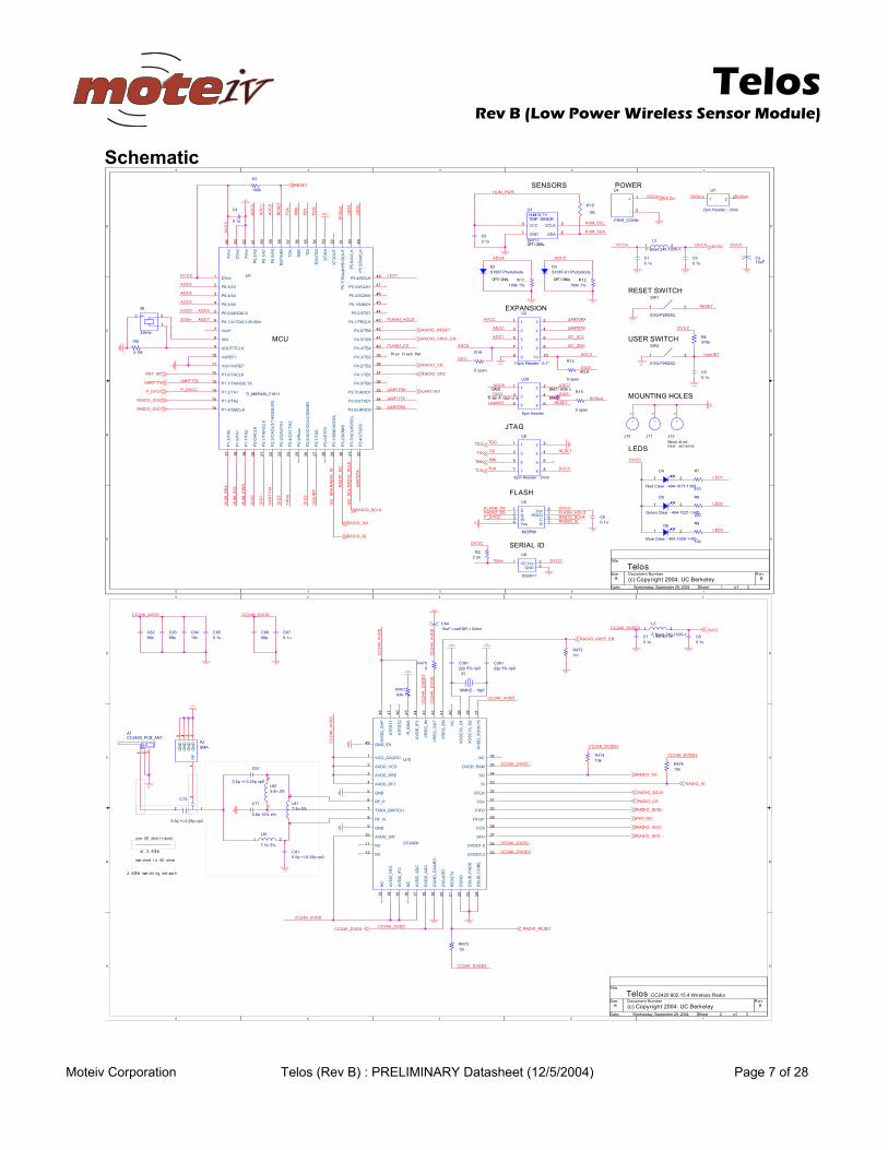
Schematic 5
5
4
4
3
3
2
2
1
1
D D
C C
B B
A A
niCCV
1DEL
TESER
2DEL
3DEL
CCVD
LCS_MUH
CCVA
OS_OIDAR
IS_OIDAR
SC_HSALF
4CDA
0CDA
1CDA
XR0TRAU
XT0TRAU
LCS_C2I
ADS_C2I
1OIG
6CDA 7CDA
niCCV
2OIG 3OIG
niSVS tuoSVS
CCVD_P
CCVD
KLCS_OIDARDLOH_HSALF
XT1TRAU
CCVD_P
AD
C2
DLOH_HSALF
SC_HSALF
GIO
2
2CDAR
AD
IO_S
O
5CDA
6CDA0CAD
ADS_MUH
AD
C0
7CDAniSVS
AD
C1
GIO
1
HU
M_S
CL
4CDA
LED
2
XR1TRAU
Use
rINT
RE
SET
GIO
3
3CDA
CCVD
TMS
TDO
HU
M_P
WR
HU
M_S
DA U
ART0
TX
TCK
LED
3
XR0TRAU
GIO
0
AV
CC
I2C
_SD
AR
AD
IO_S
I
TDI
SV
Sou
t
UA
RT1
RX
RWP_MUH
5CDA
1DEL
I2C
_SC
LR
AD
IO_S
CLK
XT1TRAU
tuoSVS
1Wire
CCVD
eriW1 CCVD
TESER
SMT
CCVD
CCVD
IDT
ODT
KCT CCVD
CCVD
TNIresU
TNIresU TESER
3CDA
0OIGSC_OIDAR
0OIG_OIDAR
1OIG_OIDAR
DFS_OIDAR
TESER_OIDAR
NE_FERV_OIDAR
CCVD
CCVD_P
niCCV
TESER
TNI_TKP
XT1TRAU
KLCS_OIDAR
OS_OIDAR
IS_OIDAR
XR1TRAU
SMT
IDT
ODT
KCT
eltiT
veRrebmuN tnemucoDeziS
teehS:etaD fo
yelekreB CU :4002 thgirypoC )c( B
soleTB
314002 ,92 rebmetpeS ,yadsendeW
LANOITPO
HSALF
UCM
REWOPSROSNES
SDEL
LANOITPOLANOITPO
0CAD
erutpaC AremiT
NOISNAPXE
SELOH GNITNUOM
HCTIWS TESER
HCTIWS RESU
rwP hsalF verP
0EAMD
niSVS/1CAD
KLCA
detalpnoNannetna raen
GATJ
DI LAIRES
61R
nepo 0
2DedoidotohP 7801S
1Cu1.0
5D
- raelC neerG DN-1-1201-404
1 2
0U
1161F_034PSM_IT
ccVD1
3A/3.6P2
4A/4.6P3
5A/5.6P4
0CAD/6A/6.6P5
NISVS/1CAD/7A/7.6P6
+ferV7
NIX8
KLCT/TUOX9
+FEReV01
-FEReV/-ferV11
KLCAT/0.1P21
XTLSB/0AT/1.1P31
1AT/2.1P41
2AT/3.1P51
KLCMS/4.1P61
P1.
5/TA
017
P1.
6/TA
118
P1.
7/TA
219
P2.
0/A
CLK
20
P2.
1/TA
INC
LK21
P2.
2/C
AO
UT/
TA0/
BS
LRX
22
P2.
3/C
A0/
TA1
23
P2.
4/C
A1/
TA2
24
P2.
5/R
osc
25
P2.
6/A
DC
12C
LK/D
MA
E0
26
P2.
7/TA
027
P3.
0/S
TE0
28
P3.
1/S
IMO
0/S
DA
29
P3.
2/S
OM
I030
P3.
3/U
CLK
0/S
CL
31
P3.
4/U
TXD
032
0DXRU/5.3P 33
1DXTU/6.3P 43
1DXRU/7.3P 53
0BT/0.4P 63
1BT/1.4P 73
2BT/2.4P 83
3BT/3.4P 93
4BT/4.4P 04
5BT/5.4P 14
6BT/6.4P 24
KLCBT/7.4P 34
1ETS/0.5P 44
1OMIS/1.5P 54
1IMOS/2.5P 64
1KLCU/3.5P 74
KLCM/4.5P 84
P5.
5/S
MC
LK49
P5.
6/A
CLK
50
P5.
7/TB
outH
/SV
SO
UT
51
XT2
OU
T52
XT2
IN53
TDO
/TD
I54
TDI
55
TMS
56
TCK
57
RS
T/N
MI
58
P6.
0/A
059
P6.
1/A
160
P6.
2/A
261
AV
ss62
DV
ss63
AV
cc64
4C
u1.0
9Cu1.0
01R
k01
2L
1-5301-042 daeB F1 2
01J
11
3CFu01
8R
022
5R
M1.5
41R
nepo 0
5Cu1.0
4D
DN-1-7101-404 - raelC deR
1 2
11R%1 k001
2WS
Q20K2P-QVE
1 2
51R
nepo 0
11J
11
3DotohP 10-7801S edoid
82U
redaeH nip6
11 2 2
33 4 4
55 6 6
8U
mm2 - redaeH nip8
11 2 2
33 4 4
55 6 6
77 8 8
1R
k001
6D
DN-1-8201-404 - raelC eulB
1 2
/YTIDIMUHROSNES PMET
3U
11THS
KLCS 3CCV4
DNG1 ADS 2
DNG
0X
zHk23
1
23
6Cu1.0
2Cu1.0
21J
11
7R
074
4U
NNOC_RWP
+ 1
- 2
9U
1142SD
O/I1 ccV 2DNG 3
9R
001
2U
H nip01 "1.0 - redae
11 2 2
33 4 4
55 6 6
77 8 8
99 01 01
7U
mm2 - redaeH nip2
11 2 2
5U
08P52M
S1Q2W3
ssV4 D 5C 6DLOH 7ccV 8
21R%1 k001
2Rk2.2
1WS
Q20K2P-QVE
1 2
4Rk074
5
5
4
4
3
3
2
2
1
1
D D
C C
B B
A A
DDVA_K42CC
3DDVD_K42CC
DDVA_K42CC
DDVD_K42CC
CC
24K
_AV
DD
CC
24K
_DV
DD
3
CC
24K
_AV
DD
DDVD_K42CC
DDVD_K42CC
3DDVD_K42CC
CC
24K
_DV
DD
3DDVD_K42CC
DDVD_K42CCDDVA_K42CC
3DDVD_K42CC
3DDVD_K42CC
CC
24K
_AV
DD
TESER_OIDAR
DFS_OIDAR
CCVD
0OIG_OIDAR
TNI_TKP
OS_OIDAR
KLCS_OIDAR
IS_OIDAR
SC_OIDAR
1OIG_OIDAR
NE_FERV_OIDAR
DDVD_K42CC
eltiT
veRrebmuN tnemucoDeziS
teehS:etaD fo
yelekreB CU :4002 thgirypoC )c( B
soleTB
324002 ,92 rebmetpeS ,yadsendeW
4.51.208 0242CC oidaR sseleriW
zHG4.2 ta
noitalosi
05 esu secart mho
zHG4.2 krowten gnihctam
smho 05 ot dehctam
18L
%5 n5.71 2
3L
1-5301-042 daeB F1 2
183C0pn %5 p22
1X
fp61 - ZHM61
48Cn01
1ATNA_BCP_0242CC
1 2 3
7Cu1.0
16L%5 n5.7
1
2
68Cp86
37C
0pn p52.0-/+ p6.5
12
3
674Rk01
28Cp86
274Rm1
26L%5 n6.5
1
2
78Cu1.0 8C
u1.0
38Cp86
374Rm1
18C0pn p52.0-/+ p5.0
01U
0242CC
DRUAG_OCV1
OCV_DDVA2
ERP_DDVA3
1FR_DDVA4
DNG5
P_FR6
HCTIWS_XRXT7
N_FR8
DNG9
WS_DDVA01
CN11
CN21
NC
13
AV
DD
_RF2
14
AV
DD
_IF2
15
NC
16
AV
DD
_AD
C17
DV
DD
_AD
C18
DG
ND
_GU
AR
D19
DG
UA
RD
20
RE
SE
Tn21
DG
ND
22
DS
UB
_PA
DS
23
DS
UB
_CO
RE
24
3.3DDVD 52
8.1DDVD 62
DFS 72
ACC 82
POFIF 92
OFIF 03
nSC 13
KLCS 23
IS 33
OS 43
MAR_DDVD 53
CN 63
AV
DD
_XO
SC
1637
XO
SC
16_Q
238
XO
SC
16_Q
139
NC
40
VR
EG
_EN
41
VR
EG
_OU
T42
VR
EG
_IN
43
AV
DD
_IF1
44
R_B
IAS
45
ATE
ST2
46
ATE
ST1
47
AV
DD
_CH
P48
XE_DNG94
58Cu1.0
474Rk01
2AAMS
RF
1G
ND
2G
ND
3G
ND
4G
ND
5
46C < RSEwoL Fu01 mho5
16C
0pn p52.0-/+ p5.0
574R0
193C0pn %5 p22
154R%1 k34
17C
r5x %01 p6.5
Telos
Rev B (Low Power Wireless Sensor Module)
Moteiv Corporation Telos (Rev B) : PRELIMINARY Datasheet (12/5/2004) Page 8 of 28
5
5
4
4
3
3
2
2
1
1
D D
C C
B B
A A
CCV_U
CCV_U
CCV_U
CCVA_U
3.3CCV_U
+BSU
-BSU
SCEEKSEE
ATADEE
CCV_U
CCV_USCEE
KSEE
ATADEE
niCCV
STR
CCV_U3.3CCV_U
CCVD_P
DXRDXT
CCVD_P
RTD
DV
CC
STRRTD
TESERKCT
KCT
CCVD
RTDRSDIR
SMTIDTODT
KCT
CCVD_P
DXR
CCVD_P
CCVD_PXT1TRAU
DXT XR1TRAU
DV
CC
DCD
DCDIR
RSD
niCCVCCVD_P
CCVD
TESERKCT
SMTIDTODT
KCT
XT1TRAU
XR1TRAU
CCVD
eltiT
veRrebmuN tnemucoDeziS
teehS:etaD fo
yelekreB CU :4002 thgirypoC )c( B
soleTB
334002 ,92 rebmetpeS ,yadsendeW
gnimmargorP / laireS gnidaeR rof desU dna stcennoC BSU aiv derewoP
ECAFRETNI BSU
RREFFUB O/I NOITINGOCER ECNEUQES TESE
MORPEE NOITACIFITNEDI BSU
REWOP ETOMRETLIF REWOP BSU
ecafretnI BSU
02L
1-5301-042 daeB F1 2
23Rm1
22U
A BSU
4 4
3 3
2 2
1 1
02R074
03Rk01
22Cu1.0
DNG
3X
rotanoser M6
1
23
42Cu1.0
52U33PR55CT
GN
D1
niV 2tuoV3
12Cn33
92Rk01
02D
- raelC neerG DN-1-1201-404
12
URB517GDA72U
1S5 2S7 3S9 4S11 5S41 6S61 7S81 8S02 8D 917D 716D 515D 314D 213D 012D 81D 6
ADS3KLCS1
0A421A22
VC
C2
GN
D4
VS
S21
TSR32
22R
72
52Cu01
32U
64C39
SC1
KS2
NID3
TUOD4 DNG 5
CN 6
CN 7
CCV 8
72R
k2.2
12D
DN-1-7101-404 - raelC deR
12
22D
A301DSLL
1 2
02C
u1.0
52R
001
02U
MB232TF
TUO3V36
MDBSU8
PDBSU7
#TUOTSR5#TESER4
NITX72
TUOTX82SCEE23KSEE1
ATADEE2TSET13
AG
ND
29
GN
D9
GN
D17
#PEELS 01#NERWP 51LTCRWP 41
#DELXR 11#DELXT 21NEDXT 61
#IR 81#DCD 91#RSD 02#RTD 12#STC 22#STR 32DXR 42DXT 52VC
CIO
13
VC
C26
VC
C3
AV
CC
30
32R
72
82R
k01
32Cu1.0
621ZW7CN92U
EO11A12 Y1 6
EO27A25 Y2 3
Vcc
8G
nd4
42R
k5.1
62R
001
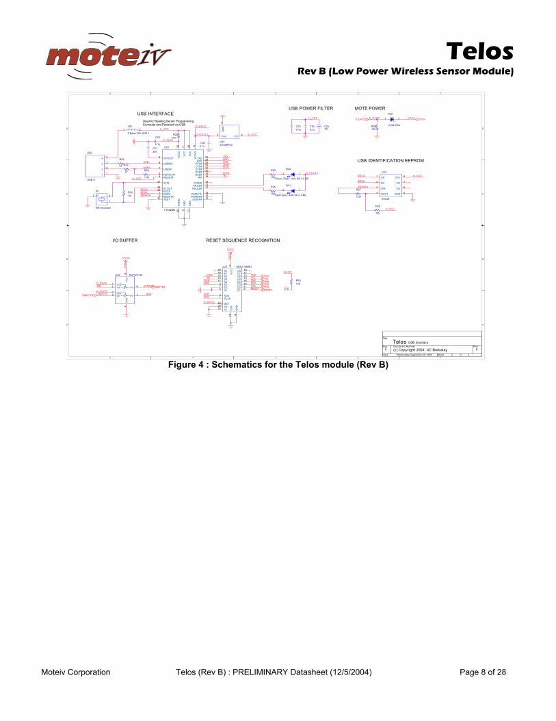
Figure 4 : Schematics for the Telos module (Rev B)
Telos
Rev B (Low Power Wireless Sensor Module)
Moteiv Corporation Telos (Rev B) : PRELIMINARY Datasheet (12/5/2004) Page 9 of 28
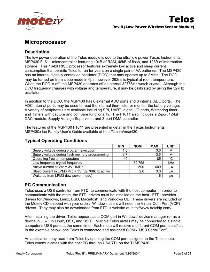
Microprocessor Description The low power operation of the Telos module is due to the ultra low power Texas Instruments MSP430 F1611 microcontroller featuring 10kB of RAM, 48kB of flash, and 128B of information storage. This 16-bit RISC processor features extremely low active and sleep current consumption that permits Telos to run for years on a single pair of AA batteries. The MSP430 has an internal digitally controlled oscillator (DCO) that may operate up to 8MHz. The DCO may be turned on from sleep mode in 6µs, however 292ns is typical at room temperature. When the DCO is off, the MSP430 operates off an eternal 32768Hz watch crystal. Although the DCO frequency changes with voltage and temperature, it may be calibrated by using the 32kHz oscillator. In addition to the DCO, the MSP430 has 8 external ADC ports and 8 internal ADC ports. The ADC internal ports may be used to read the internal thermistor or monitor the battery voltage. A variety of peripherals are available including SPI, UART, digital I/O ports, Watchdog timer, and Timers with capture and compare functionality. The F1611 also includes a 2-port 12-bit DAC module, Supply Voltage Supervisor, and 3-port DMA controller. The features of the MSP430 F1611 are presented in detail in the Texas Instruments MSP430x1xx Family User’s Guide available at http://ti.com/msp430.
Typical Operating Conditions MIN NOM MAX UNIT Supply voltage during program execution 1.8 3.6 V Supply voltage during flash memory programming 2.7 3.6 V Operating free air temperature -40 85 oC Low frequency crystal frequency 32.768 kHz Active current at Vcc = 3V, 1MHz 500 600 µA Sleep current in LPM3 Vcc = 3V, 32.768kHz active 2.6 3.0 µA Wake up from LPM3 (low power mode) 6 µs
PC Communication Telos uses a USB controller from FTDI to communicate with the host computer. In order to communicate with the mote, the FTDI drivers must be installed on the host. FTDI provides drivers for Windows, Linux, BSD, Macintosh, and Windows CE. These drivers are included on the Moteiv CD shipped with your order. Windows users will need the Virtual Com Port (VCP) drivers. They may also be downloaded from FTDI’s website at: http://www.ftdichip.com/ After installing the driver, Telos appears as a COM port in Windows’ device manager (or as a device in /dev in Linux, OSX, and BSD). Multiple Telos motes may be connected to a single computer’s USB ports at the same time. Each mote will receive a different COM port identifier. In the example below, one Telos is connected and assigned COM6 “USB Serial Port”. An application may read from Telos by opening the COM port assigned to the Telos mote. Telos communicates with the host PC through USART1 on the TI MSP430.
Telos
Rev B (Low Power Wireless Sensor Module)
Moteiv Corporation Telos (Rev B) : PRELIMINARY Datasheet (12/5/2004) Page 10 of 28
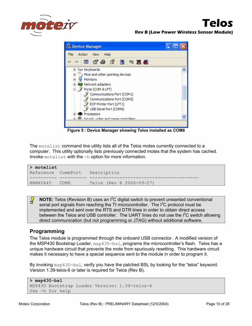
Figure 5 : Device Manager showing Telos installed as COM6
The motelist command line utility lists all of the Telos motes currently connected to a computer. This utility optionally lists previously connected motes that the system has cached. Invoke motelist with the -h option for more information. > motelist Reference CommPort Description ---------- ---------- ---------------------------------------- M4MXVA4Y COM6 Telos (Rev B 2004-09-27)
NOTE: Telos (Revision B) uses an I2C digital switch to prevent unwanted conventional serial port signals from reaching the TI microcontroller. The I2C protocol must be implemented and sent over the RTS and DTR lines in order to obtain direct access between the Telos and USB controller. The UART lines do not use the I2C switch allowing direct communication (but not programming or JTAG) without additional software.
Programming The Telos module is programmed through the onboard USB connector. A modified version of the MSP430 Bootstrap Loader, msp430-bsl, programs the microcontroller’s flash. Telos has a unique hardware circuit that prevents the mote from spuriously resetting. This hardware circuit makes it necessary to have a special sequence sent to the module in order to program it. By invoking msp430-bsl, verify you have the patched BSL by looking for the “telos” keyword. Version 1.39-telos-6 or later is required for Telos (Rev B). > msp430-bsl MSP430 Bootstrap Loader Version: 1.39-telos-6 Use -h for help
Telos
Rev B (Low Power Wireless Sensor Module)
Moteiv Corporation Telos (Rev B) : PRELIMINARY Datasheet (12/5/2004) Page 11 of 28
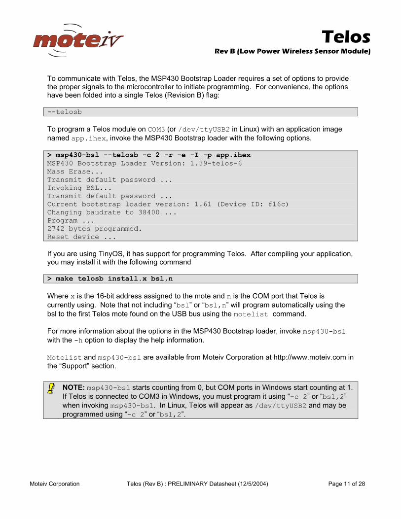
To communicate with Telos, the MSP430 Bootstrap Loader requires a set of options to provide the proper signals to the microcontroller to initiate programming. For convenience, the options have been folded into a single Telos (Revision B) flag: --telosb To program a Telos module on COM3 (or /dev/ttyUSB2 in Linux) with an application image named app.ihex, invoke the MSP430 Bootstrap loader with the following options. > msp430-bsl --telosb -c 2 -r -e -I -p app.ihex MSP430 Bootstrap Loader Version: 1.39-telos-6 Mass Erase... Transmit default password ... Invoking BSL... Transmit default password ... Current bootstrap loader version: 1.61 (Device ID: f16c) Changing baudrate to 38400 ... Program ... 2742 bytes programmed. Reset device ... If you are using TinyOS, it has support for programming Telos. After compiling your application, you may install it with the following command > make telosb install.x bsl,n Where x is the 16-bit address assigned to the mote and n is the COM port that Telos is currently using. Note that not including “bsl” or “bsl,n” will program automatically using the bsl to the first Telos mote found on the USB bus using the motelist command. For more information about the options in the MSP430 Bootstrap loader, invoke msp430-bsl with the -h option to display the help information. Motelist and msp430-bsl are available from Moteiv Corporation at http://www.moteiv.com in the “Support” section.
NOTE: msp430-bsl starts counting from 0, but COM ports in Windows start counting at 1. If Telos is connected to COM3 in Windows, you must program it using “-c 2” or “bsl,2” when invoking msp430-bsl. In Linux, Telos will appear as /dev/ttyUSB2 and may be programmed using “-c 2” or “bsl,2”.
Telos
Rev B (Low Power Wireless Sensor Module)
Moteiv Corporation Telos (Rev B) : PRELIMINARY Datasheet (12/5/2004) Page 12 of 28
Block Diagram
Oscillator
SystemClock
32kHz
ACLK
SMCLK
CPU16 bit16 reg
multiply
Flash
RAM
12-bit ADC8 Channels<10µs Conv
12-bit DAC2 Channels
16-bit bus
I/O Port 3/416 I/Os
I/O Port 1/216 I/Os
Interrupts
I/O Port 5/68 I/Os
MCLK
WatchdogTimer
15/16 bit
Timer A3 CC reg
ComparatorA
Timer B7 CC reg
USART0UART
SPII2C
DMAController3 Channels
USART1UART
SPI
CC2420 RadioInterrupts & SPI
PCUART via USB
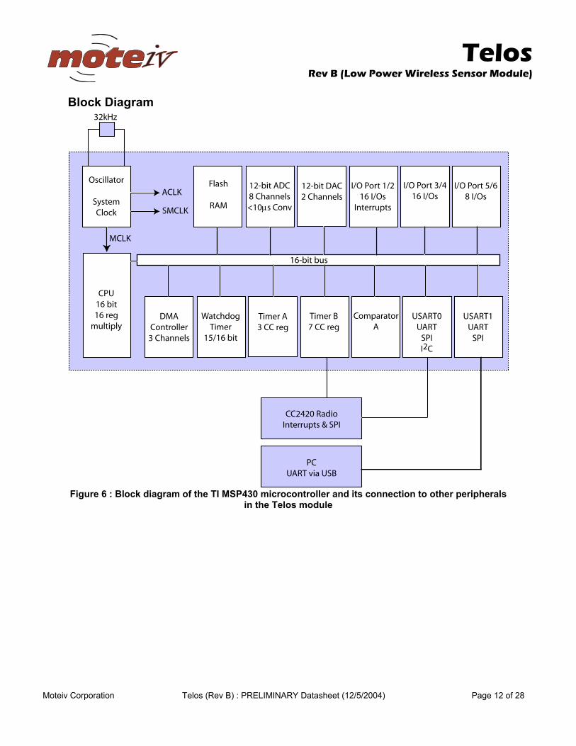
Figure 6 : Block diagram of the TI MSP430 microcontroller and its connection to other peripherals
in the Telos module
Telos
Rev B (Low Power Wireless Sensor Module)
Moteiv Corporation Telos (Rev B) : PRELIMINARY Datasheet (12/5/2004) Page 13 of 28
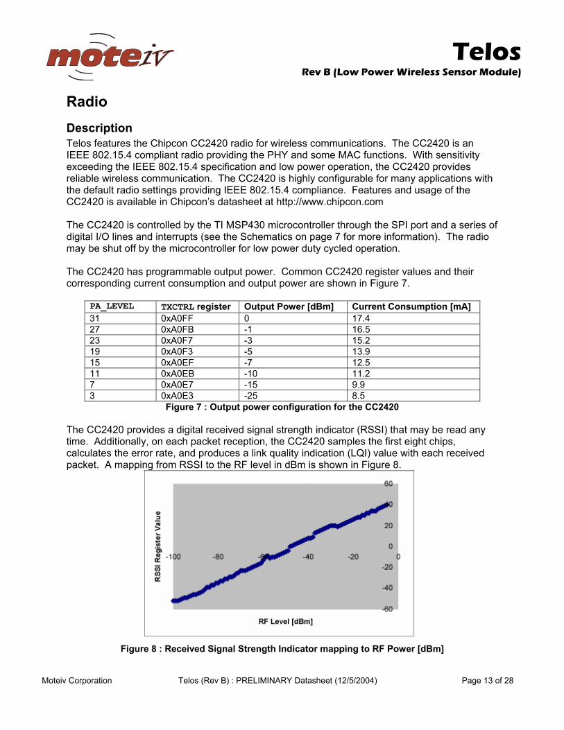
Radio Description Telos features the Chipcon CC2420 radio for wireless communications. The CC2420 is an IEEE 802.15.4 compliant radio providing the PHY and some MAC functions. With sensitivity exceeding the IEEE 802.15.4 specification and low power operation, the CC2420 provides reliable wireless communication. The CC2420 is highly configurable for many applications with the default radio settings providing IEEE 802.15.4 compliance. Features and usage of the CC2420 is available in Chipcon’s datasheet at http://www.chipcon.com The CC2420 is controlled by the TI MSP430 microcontroller through the SPI port and a series of digital I/O lines and interrupts (see the Schematics on page 7 for more information). The radio may be shut off by the microcontroller for low power duty cycled operation. The CC2420 has programmable output power. Common CC2420 register values and their corresponding current consumption and output power are shown in Figure 7.
PA_LEVEL TXCTRL register Output Power [dBm] Current Consumption [mA] 31 0xA0FF 0 17.4 27 0xA0FB -1 16.5 23 0xA0F7 -3 15.2 19 0xA0F3 -5 13.9 15 0xA0EF -7 12.5 11 0xA0EB -10 11.2 7 0xA0E7 -15 9.9 3 0xA0E3 -25 8.5
Figure 7 : Output power configuration for the CC2420 The CC2420 provides a digital received signal strength indicator (RSSI) that may be read any time. Additionally, on each packet reception, the CC2420 samples the first eight chips, calculates the error rate, and produces a link quality indication (LQI) value with each received packet. A mapping from RSSI to the RF level in dBm is shown in Figure 8.
Figure 8 : Received Signal Strength Indicator mapping to RF Power [dBm]
Telos
Rev B (Low Power Wireless Sensor Module)
Moteiv Corporation Telos (Rev B) : PRELIMINARY Datasheet (12/5/2004) Page 14 of 28
Typical Operating Conditions MIN NOM MAX UNIT Supply voltage during radio operation (Vreg on) 2.1 3.6 V Operating free air temperature -40 85 oC RF frequency range 2400 2483.5 MHz Transmit bit rate 250 250 kbps Nominal output power -3 0 dBm Programmable output power range 40 dBm Receiver sensitivity -90 -94 dBm Current consumption: Radio transmitting at 0 dBm 17.4 mA Current consumption: Radio receiving 19.7 mA Current consumption: Radio on, Oscillator on 365 µΑ Current consumption: Idle mode, Oscillator off 20 µΑ Current consumption: Power Down mode, Vreg off 1 µΑ Voltage regulator current draw 13 20 29 µΑ Radio oscillator startup time 580 860 µs
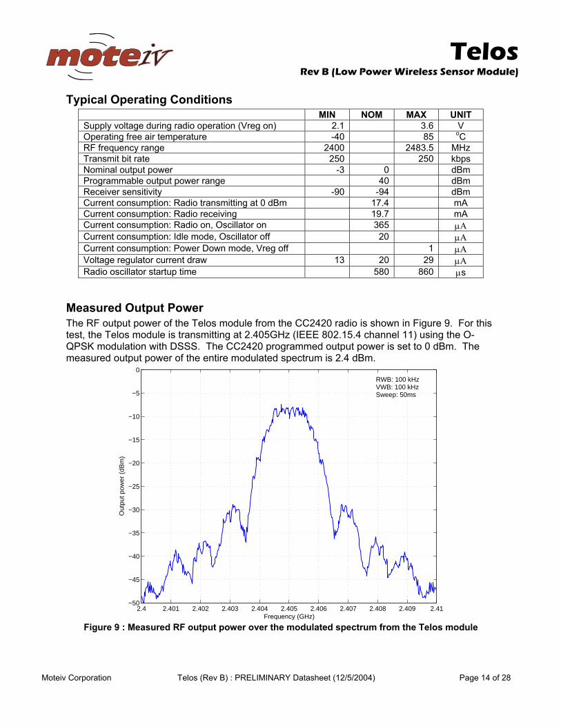
Measured Output Power The RF output power of the Telos module from the CC2420 radio is shown in Figure 9. For this test, the Telos module is transmitting at 2.405GHz (IEEE 802.15.4 channel 11) using the O-QPSK modulation with DSSS. The CC2420 programmed output power is set to 0 dBm. The measured output power of the entire modulated spectrum is 2.4 dBm.
2.4 2.401 2.402 2.403 2.404 2.405 2.406 2.407 2.408 2.409 2.41−50
−45
−40
−35
−30
−25
−20
−15
−10
−5
0
Frequency (GHz)
Out
put p
ower
(dB
m)
RWB: 100 kHzVWB: 100 kHzSweep: 50ms
Figure 9 : Measured RF output power over the modulated spectrum from the Telos module
Telos
Rev B (Low Power Wireless Sensor Module)
Moteiv Corporation Telos (Rev B) : PRELIMINARY Datasheet (12/5/2004) Page 15 of 28
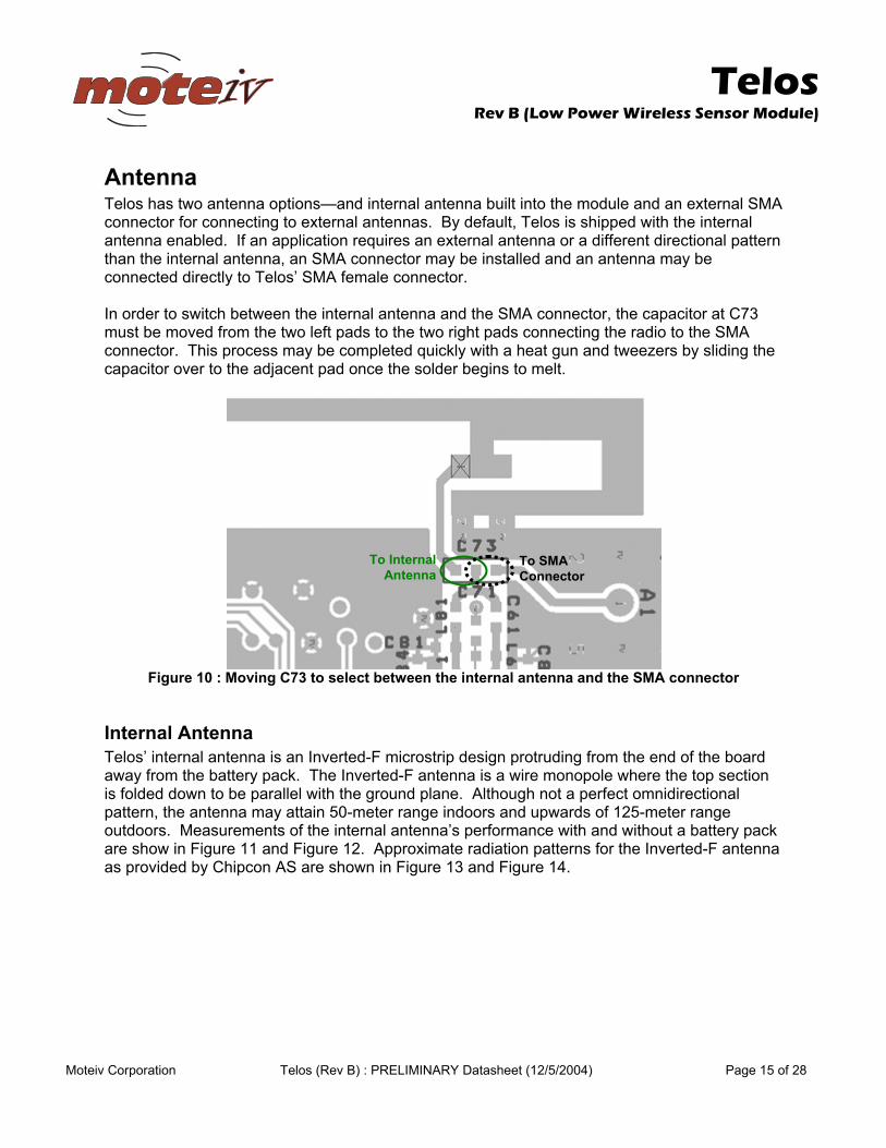
Antenna Telos has two antenna options—and internal antenna built into the module and an external SMA connector for connecting to external antennas. By default, Telos is shipped with the internal antenna enabled. If an application requires an external antenna or a different directional pattern than the internal antenna, an SMA connector may be installed and an antenna may be connected directly to Telos’ SMA female connector. In order to switch between the internal antenna and the SMA connector, the capacitor at C73 must be moved from the two left pads to the two right pads connecting the radio to the SMA connector. This process may be completed quickly with a heat gun and tweezers by sliding the capacitor over to the adjacent pad once the solder begins to melt.
Figure 10 : Moving C73 to select between the internal antenna and the SMA connector
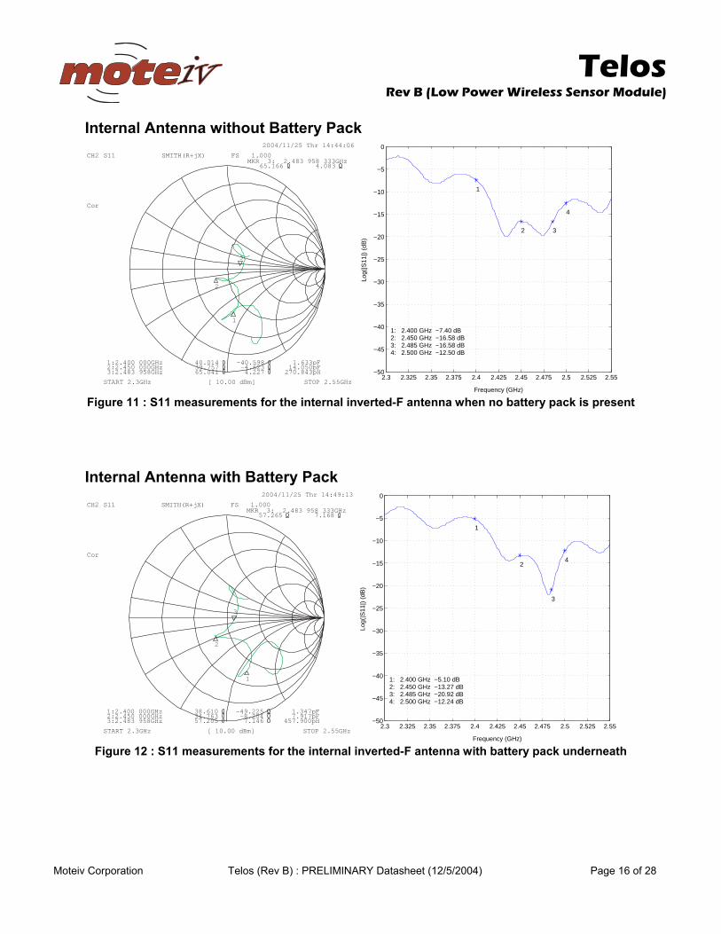
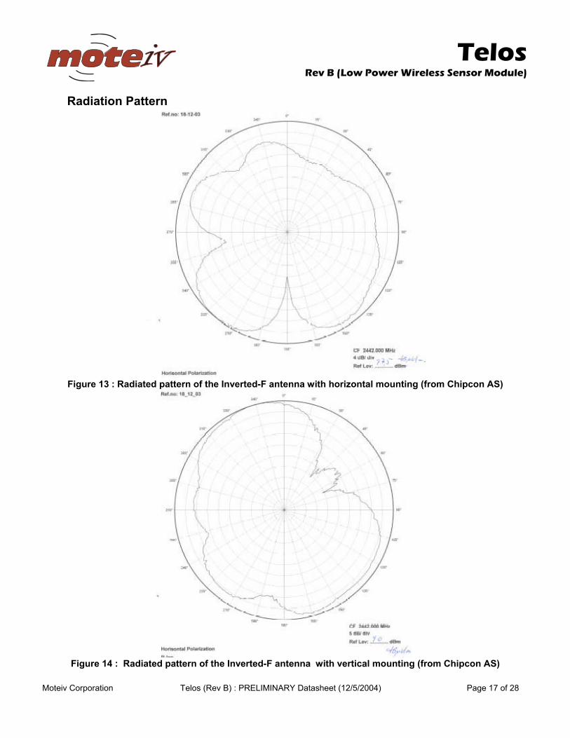
Internal Antenna Telos’ internal antenna is an Inverted-F microstrip design protruding from the end of the board away from the battery pack. The Inverted-F antenna is a wire monopole where the top section is folded down to be parallel with the ground plane. Although not a perfect omnidirectional pattern, the antenna may attain 50-meter range indoors and upwards of 125-meter range outdoors. Measurements of the internal antenna’s performance with and without a battery pack are show in Figure 11 and Figure 12. Approximate radiation patterns for the Inverted-F antenna as provided by Chipcon AS are shown in Figure 13 and Figure 14.
To InternalAntenna
To SMAConnector
Telos
Rev B (Low Power Wireless Sensor Module)
Moteiv Corporation Telos (Rev B) : PRELIMINARY Datasheet (12/5/2004) Page 16 of 28
Internal Antenna without Battery Pack 2004/11/25 Thr 14:44:06
CH2 S11 SMITH(R+jX) FS 1.000MKR 3: 2.483 958 333GHz
65.166 4.083
Cor
3:2.483 958GHz 65.041 4.227 270.843pH2:2.450 000GHz 39.757 -4.623 14.050pF1:2.400 000GHz 40.014 -40.598 1.633pF
3
1
2
START 2.3GHz [ 10.00 dBm] STOP 2.55GHz2.3 2.325 2.35 2.375 2.4 2.425 2.45 2.475 2.5 2.525 2.55
−50
−45
−40
−35
−30
−25
−20
−15
−10
−5
0
Frequency (GHz)
Log(
|S11
|) (
dB)
1
2 3
4
1: 2.400 GHz −7.40 dB2: 2.450 GHz −16.58 dB3: 2.485 GHz −16.58 dB4: 2.500 GHz −12.50 dB
Figure 11 : S11 measurements for the internal inverted-F antenna when no battery pack is present
Internal Antenna with Battery Pack 2004/11/25 Thr 14:49:13
CH2 S11 SMITH(R+jX) FS 1.000MKR 3: 2.483 958 333GHz
57.265 7.168
Cor
3:2.483 958GHz 57.205 7.146 457.900pH2:2.450 000GHz 34.763 -8.204 7.917pF1:2.400 000GHz 38.610 -49.225 1.347pF
1
2
3
START 2.3GHz [ 10.00 dBm] STOP 2.55GHz2.3 2.325 2.35 2.375 2.4 2.425 2.45 2.475 2.5 2.525 2.55
−50
−45
−40
−35
−30
−25
−20
−15
−10
−5
0
Frequency (GHz)
Log(
|S11
|) (
dB)
1
2
3
4
1: 2.400 GHz −5.10 dB2: 2.450 GHz −13.27 dB3: 2.485 GHz −20.92 dB4: 2.500 GHz −12.24 dB
Figure 12 : S11 measurements for the internal inverted-F antenna with battery pack underneath
Telos
Rev B (Low Power Wireless Sensor Module)
Moteiv Corporation Telos (Rev B) : PRELIMINARY Datasheet (12/5/2004) Page 17 of 28
Radiation Pattern
Figure 13 : Radiated pattern of the Inverted-F antenna with horizontal mounting (from Chipcon AS)
Figure 14 : Radiated pattern of the Inverted-F antenna with vertical mounting (from Chipcon AS)
Telos
Rev B (Low Power Wireless Sensor Module)
Moteiv Corporation Telos (Rev B) : PRELIMINARY Datasheet (12/5/2004) Page 18 of 28
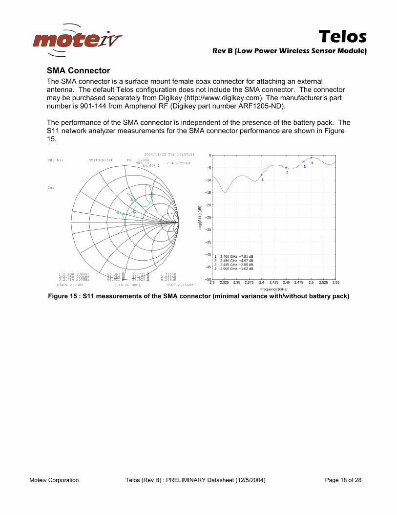
SMA Connector The SMA connector is a surface mount female coax connector for attaching an external antenna. The default Telos configuration does not include the SMA connector. The connector may be purchased separately from Digikey (http://www.digikey.com). The manufacturer’s part number is 901-144 from Amphenol RF (Digikey part number ARF1205-ND). The performance of the SMA connector is independent of the presence of the battery pack. The S11 network analyzer measurements for the SMA connector performance are shown in Figure 15.
2004/11/25 Thr 13:37:58
CH1 S11MKR 3: 2.486 25GHz
3:2.486 250GHz 64.625 97.928 6.268nH2:2.450 000GHz 43.059 44.470 2.888nH1:2.400 000GHz 63.063 29.795 1.975nH
1
2
3
START 2.3GHz [ 10.00 dBm] STOP 2.55GHz
SMITH(R+jX) FS 1.000
64.698
Cor
2.3 2.325 2.35 2.375 2.4 2.425 2.45 2.475 2.5 2.525 2.55−50
−45
−40
−35
−30
−25
−20
−15
−10
−5
0
Frequency (GHz)
Log(
|S11
|) (
dB)
1
2
34
1: 2.400 GHz −7.91 dB2: 2.450 GHz −4.97 dB3: 2.485 GHz −2.55 dB4: 2.500 GHz −1.02 dB
Figure 15 : S11 measurements of the SMA connector (minimal variance with/without battery pack)
Telos
Rev B (Low Power Wireless Sensor Module)
Moteiv Corporation Telos (Rev B) : PRELIMINARY Datasheet (12/5/2004) Page 19 of 28
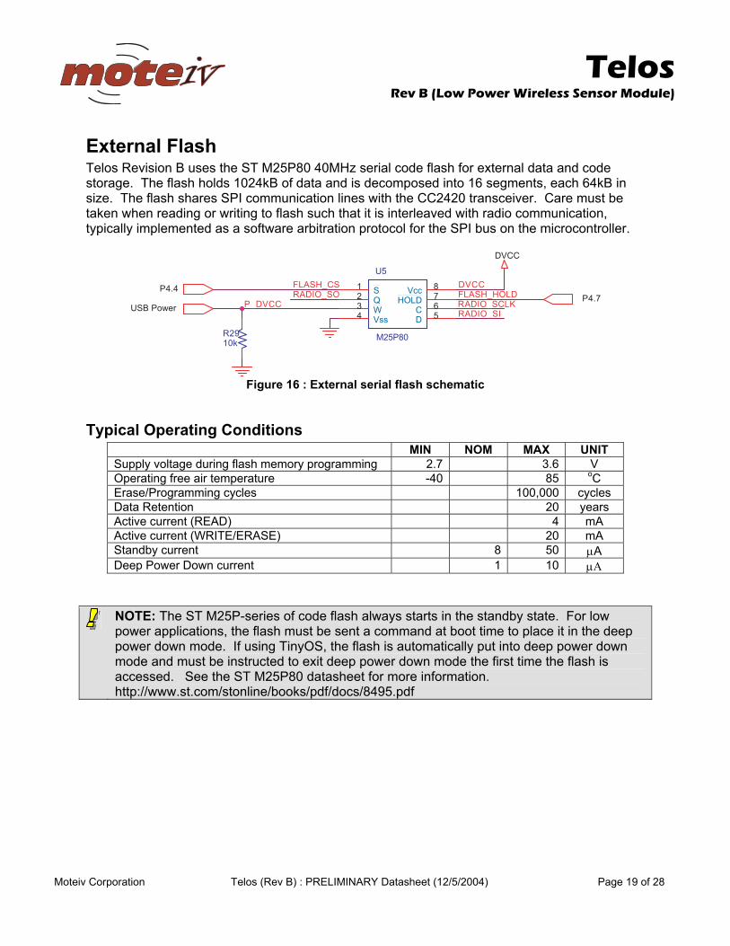
External Flash Telos Revision B uses the ST M25P80 40MHz serial code flash for external data and code storage. The flash holds 1024kB of data and is decomposed into 16 segments, each 64kB in size. The flash shares SPI communication lines with the CC2420 transceiver. Care must be taken when reading or writing to flash such that it is interleaved with radio communication, typically implemented as a software arbitration protocol for the SPI bus on the microcontroller.
SC_HSALF
CCVD_P
CCVD
KLCS_OIDAROS_OIDAR
IS_OIDAR
DLOH_HSALFrewoP BSU
4.4P7.4P
CCVD
92Rk01
5U
08P52M
S1Q2W3
ssV4 D 5C 6DLOH 7ccV 8
Figure 16 : External serial flash schematic
Typical Operating Conditions MIN NOM MAX UNIT Supply voltage during flash memory programming 2.7 3.6 V Operating free air temperature -40 85 oC Erase/Programming cycles 100,000 cycles Data Retention 20 years Active current (READ) 4 mA Active current (WRITE/ERASE) 20 mA Standby current 8 50 µA Deep Power Down current 1 10 µΑ
NOTE: The ST M25P-series of code flash always starts in the standby state. For low power applications, the flash must be sent a command at boot time to place it in the deep power down mode. If using TinyOS, the flash is automatically put into deep power down mode and must be instructed to exit deep power down mode the first time the flash is accessed. See the ST M25P80 datasheet for more information. http://www.st.com/stonline/books/pdf/docs/8495.pdf
Telos
Rev B (Low Power Wireless Sensor Module)
Moteiv Corporation Telos (Rev B) : PRELIMINARY Datasheet (12/5/2004) Page 20 of 28
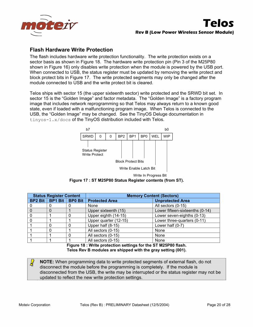
Flash Hardware Write Protection The flash includes hardware write protection functionality. The write protection exists on a sector basis as shown in Figure 18. The hardware write protection pin (Pin 3 of the M25P80 shown in Figure 16) only disables write protection when the module is powered by the USB port. When connected to USB, the status register must be updated by removing the write protect and block protect bits in Figure 17. The write protected segments may only be changed after the module connected to USB and the write protect bit is cleared. Telos ships with sector 15 (the upper sixteenth sector) write protected and the SRWD bit set. In sector 15 is the “Golden Image” and factor metadata. The “Golden Image” is a factory program image that includes network reprogramming so that Telos may always return to a known good state, even if loaded with a malfunctioning program image. When Telos is connected to the USB, the “Golden Image” may be changed. See the TinyOS Deluge documentation in tinyos-1.x/docs of the TinyOS distribution included with Telos.
b7 b0
SRWD 0 0 BP2 BP1 BP0 WEL WIP
Status Register Write Protect
Block Protect Bits
Write Enable Latch Bit
Write In Progress Bit Figure 17 : ST M25P80 Status Register contents (from ST).
Status Register Content Memory Content (Sectors) BP2 Bit BP1 Bit BP0 Bit Protected Area Unprotected Area 0 0 0 None All sectors (0-15) 0 0 1 Upper sixteenth (15) Lower fifteen-sixteenths (0-14) 0 1 0 Upper eighth (14-15) Lower seven-eighths (0-13) 0 1 1 Upper quarter (12-15) Lower three-quarters (0-11) 1 0 0 Upper half (8-15) Lower half (0-7) 1 0 1 All sectors (0-15) None 1 1 0 All sectors (0-15) None 1 1 1 All sectors (0-15) None
Figure 18 : Write protection settings for the ST M25P80 flash. Telos Rev B modules are shipped with the gray setting (001).
NOTE: When programming data to write protected segments of external flash, do not disconnect the module before the programming is completely. If the module is disconnected from the USB, the write may be interrupted or the status register may not be updated to reflect the new write protection settings.
Telos
Rev B (Low Power Wireless Sensor Module)
Moteiv Corporation Telos (Rev B) : PRELIMINARY Datasheet (12/5/2004) Page 21 of 28
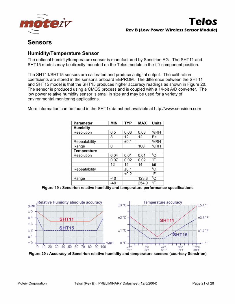
Sensors Humidity/Temperature Sensor The optional humidity/temperature sensor is manufactured by Sensirion AG. The SHT11 and SHT15 models may be directly mounted on the Telos module in the U3 component position. The SHT11/SHT15 sensors are calibrated and produce a digital output. The calibration coefficients are stored in the sensor’s onboard EEPROM. The difference between the SHT11 and SHT15 model is that the SHT15 produces higher accuracy readings as shown in Figure 20. The sensor is produced using a CMOS process and is coupled with a 14-bit A/D converter. The low power relative humidity sensor is small in size and may be used for a variety of environmental monitoring applications. More information can be found in the SHT1x datasheet available at http://www.sensirion.com
Parameter MIN TYP MAX UnitsHumidity Resolution 0.5 0.03 0.03 %RH 8 12 12 Bit Repeatability ±0.1 %RH Range 0 100 %RH Temperature Resolution 0.04 0.01 0.01 oC 0.07 0.02 0.02 oF 12 14 14 bit Repeatability ±0.1 oC ±0.2 oF Range -40 123.8 oC -40 254.9 oF
Figure 19 : Sensirion relative humidity and temperature performance specifications
%RH
Relative Humidity absolute accuracy
± 0
± 1
± 2
± 3
± 4
± 5
0 30 402010 8050 10070 9060
%RH
SHT15
SHT11
Temperature accuracy
0 °C
±1 °C
±2 °C
-40°C 0°C 40°C 80°C 120°C
±3 °C
0 °F
±1.8 °F
±3.6 °F
±5.4 °F
-40°F 32°F 104°F 176°F 248°F
SHT11
SHT15
Figure 20 : Accuracy of Sensirion relative humidity and temperature sensors (courtesy Sensirion)
Telos
Rev B (Low Power Wireless Sensor Module)
Moteiv Corporation Telos (Rev B) : PRELIMINARY Datasheet (12/5/2004) Page 22 of 28
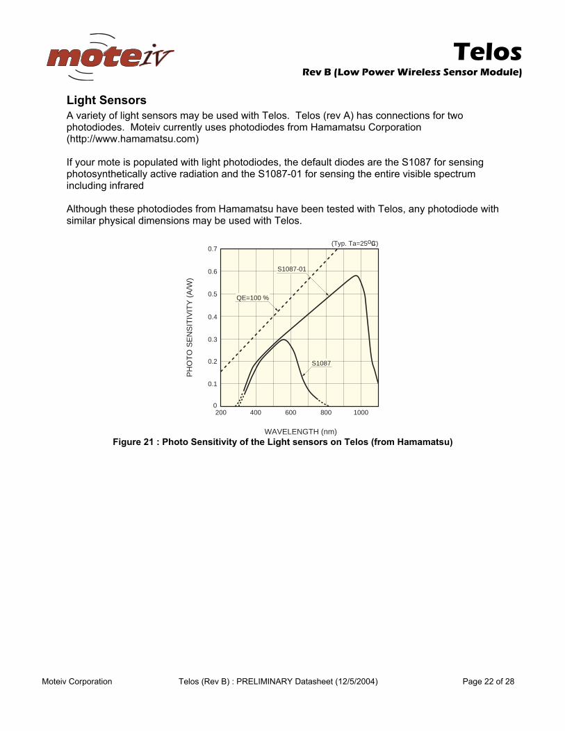
Light Sensors A variety of light sensors may be used with Telos. Telos (rev A) has connections for two photodiodes. Moteiv currently uses photodiodes from Hamamatsu Corporation (http://www.hamamatsu.com) If your mote is populated with light photodiodes, the default diodes are the S1087 for sensing photosynthetically active radiation and the S1087-01 for sensing the entire visible spectrum including infrared Although these photodiodes from Hamamatsu have been tested with Telos, any photodiode with similar physical dimensions may be used with Telos.
0
0.1
0.2
0.3
0.4
0.7
200 400 600 800 1000
WAVELENGTH (nm)
PH
OT
O S
EN
SIT
IVIT
Y (
A/W
)
(Typ. Ta=25oûC)
0.5
0.6
S1087
S1087-01
QE=100 %
Figure 21 : Photo Sensitivity of the Light sensors on Telos (from Hamamatsu)
Telos
Rev B (Low Power Wireless Sensor Module)
Moteiv Corporation Telos (Rev B) : PRELIMINARY Datasheet (12/5/2004) Page 23 of 28
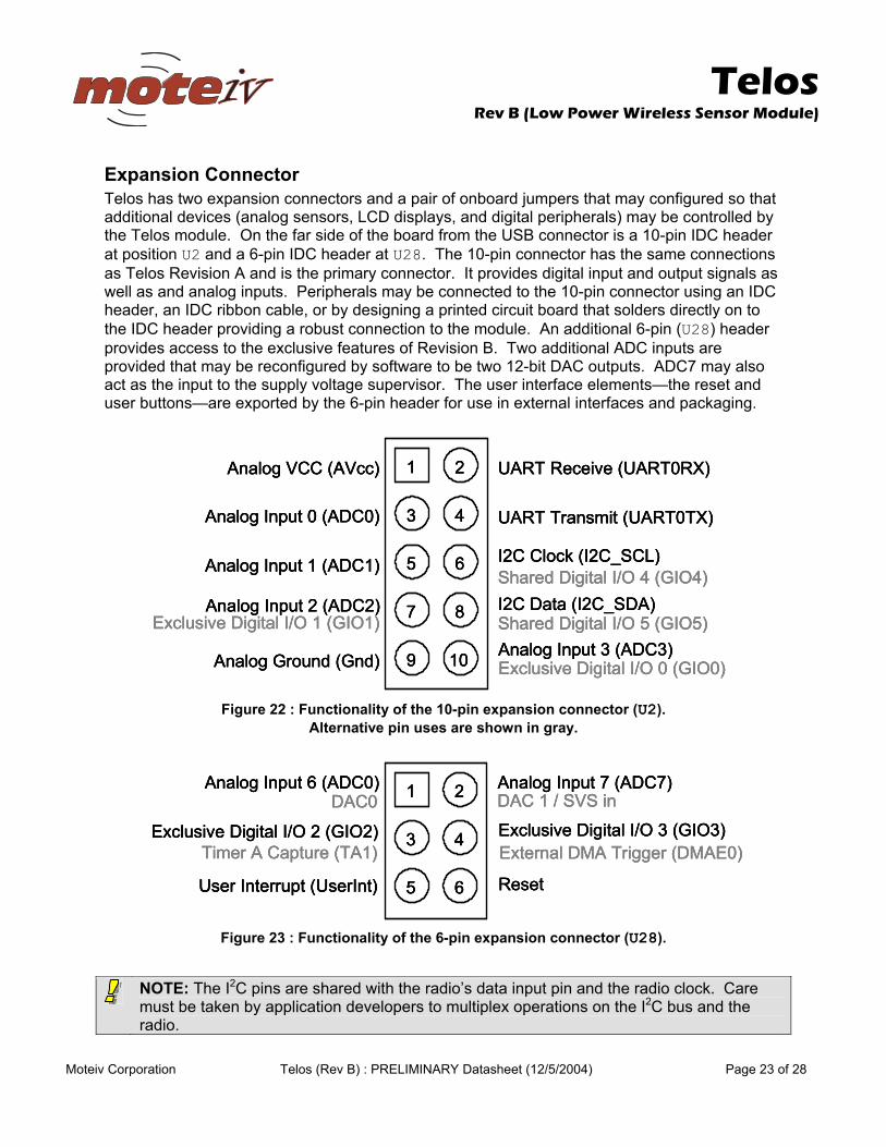
Expansion Connector Telos has two expansion connectors and a pair of onboard jumpers that may configured so that additional devices (analog sensors, LCD displays, and digital peripherals) may be controlled by the Telos module. On the far side of the board from the USB connector is a 10-pin IDC header at position U2 and a 6-pin IDC header at U28. The 10-pin connector has the same connections as Telos Revision A and is the primary connector. It provides digital input and output signals as well as and analog inputs. Peripherals may be connected to the 10-pin connector using an IDC header, an IDC ribbon cable, or by designing a printed circuit board that solders directly on to the IDC header providing a robust connection to the module. An additional 6-pin (U28) header provides access to the exclusive features of Revision B. Two additional ADC inputs are provided that may be reconfigured by software to be two 12-bit DAC outputs. ADC7 may also act as the input to the supply voltage supervisor. The user interface elements—the reset and user buttons—are exported by the 6-pin header for use in external interfaces and packaging.
2
43
65
87
109
1Analog VCC (AVcc)
Analog Input 0 (ADC0)
Analog Input 1 (ADC1)
Analog Input 2 (ADC2)Exclusive Digital I/O 1 (GIO1)
Analog Ground (Gnd)
UART Receive (UART0RX)
UART Transmit (UART0TX)
I2C Clock (I2C_SCL)Shared Digital I/O 4 (GIO4)I2C Data (I2C_SDA)Shared Digital I/O 5 (GIO5)
Exclusive Digital I/O 0 (GIO0)Analog Input 3 (ADC3)
Figure 22 : Functionality of the 10-pin expansion connector (U2).
Alternative pin uses are shown in gray.
2
43
65
1Analog Input 6 (ADC0)
Exclusive Digital I/O 2 (GIO2)
Analog Input 7 (ADC7)DAC 1 / SVS inDAC0Exclusive Digital I/O 3 (GIO3)
User Interrupt (UserInt) Reset
Timer A Capture (TA1) External DMA Trigger (DMAE0)
2
43
65
1Analog Input 6 (ADC0)
Exclusive Digital I/O 2 (GIO2)
Analog Input 7 (ADC7)DAC 1 / SVS inDAC0Exclusive Digital I/O 3 (GIO3)
User Interrupt (UserInt) Reset
Timer A Capture (TA1) External DMA Trigger (DMAE0)
2
43
65
1Analog Input 6 (ADC0)
Exclusive Digital I/O 2 (GIO2)
Analog Input 7 (ADC7)DAC 1 / SVS inDAC0Exclusive Digital I/O 3 (GIO3)
User Interrupt (UserInt) Reset
Timer A Capture (TA1) External DMA Trigger (DMAE0)
Figure 23 : Functionality of the 6-pin expansion connector (U28).
NOTE: The I2C pins are shared with the radio’s data input pin and the radio clock. Care must be taken by application developers to multiplex operations on the I2C bus and the radio.
Telos
Rev B (Low Power Wireless Sensor Module)
Moteiv Corporation Telos (Rev B) : PRELIMINARY Datasheet (12/5/2004) Page 24 of 28
If expansion pin 10 (ADC3) is used for digital I/O instead of analog inputs, R14 must be populated with a 0 ohm resistor to enable the pin for digital I/O (GIO0) on the microcontroller. R16 must be populated with a 0 ohm resistor to enable GIO1. R14 and R16 are located on the top side of Telos between the USB controller and the radio.
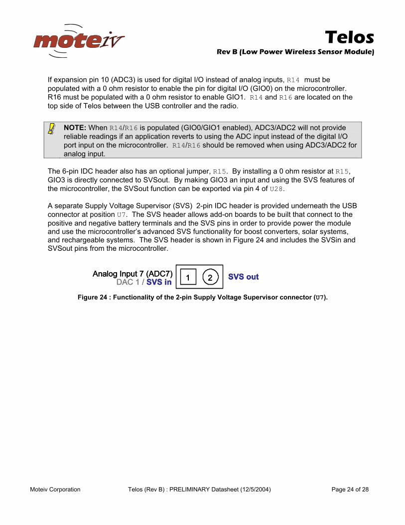
The 6-pin IDC header also has an optional jumper, R15. By installing a 0 ohm resistor at R15, GIO3 is directly connected to SVSout. By making GIO3 an input and using the SVS features of the microcontroller, the SVSout function can be exported via pin 4 of U28. A separate Supply Voltage Supervisor (SVS) 2-pin IDC header is provided underneath the USB connector at position U7. The SVS header allows add-on boards to be built that connect to the positive and negative battery terminals and the SVS pins in order to provide power the module and use the microcontroller’s advanced SVS functionality for boost converters, solar systems, and rechargeable systems. The SVS header is shown in Figure 24 and includes the SVSin and SVSout pins from the microcontroller.
21Analog Input 7 (ADC7)DAC 1 / SVS in SVS out21Analog Input 7 (ADC7)DAC 1 / SVS in SVS out21Analog Input 7 (ADC7)DAC 1 / SVS in SVS out
Figure 24 : Functionality of the 2-pin Supply Voltage Supervisor connector (U7).
NOTE: When R14/R16 is populated (GIO0/GIO1 enabled), ADC3/ADC2 will not provide reliable readings if an application reverts to using the ADC input instead of the digital I/O port input on the microcontroller. R14/R16 should be removed when using ADC3/ADC2 for analog input.
Telos
Rev B (Low Power Wireless Sensor Module)
Moteiv Corporation Telos (Rev B) : PRELIMINARY Datasheet (12/5/2004) Page 25 of 28
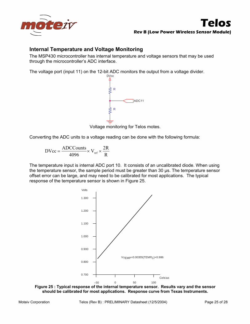
Internal Temperature and Voltage Monitoring The MSP430 microcontroller has internal temperature and voltage sensors that may be used through the microcontroller’s ADC interface. The voltage port (input 11) on the 12-bit ADC monitors the output from a voltage divider.
11CDA
ccVD
R
R
Voltage monitoring for Telos motes.
Converting the ADC units to a voltage reading can be done with the following formula:
RR2V
4096ADCCountsDVcc ref ××=
The temperature input is internal ADC port 10. It consists of an uncalibrated diode. When using the temperature sensor, the sample period must be greater than 30 µs. The temperature sensor offset error can be large, and may need to be calibrated for most applications. The typical response of the temperature sensor is shown in Figure 25.
Cels ius
Volts
0 50 100
1.000
0.800
0.900
1.100
1.200
1.300
–50
0.700
VTEMP=0.00355(TEMPC)+0.986
Figure 25 : Typical response of the internal temperature sensor. Results vary and the sensor
should be calibrated for most applications. Response curve from Texas Instruments.
Telos
Rev B (Low Power Wireless Sensor Module)
Moteiv Corporation Telos (Rev B) : PRELIMINARY Datasheet (12/5/2004) Page 26 of 28
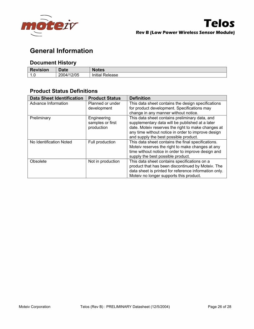
General Information Document History Revision Date Notes 1.0 2004/12/05 Initial Release
Product Status Definitions Data Sheet Identification Product Status Definition Advance Information Planned or under
development This data sheet contains the design specifications for product development. Specifications may change in any manner without notice.
Preliminary Engineering samples or first production
This data sheet contains preliminary data, and supplementary data will be published at a later date. Moteiv reserves the right to make changes at any time without notice in order to improve design and supply the best possible product.
No Identification Noted Full production This data sheet contains the final specifications. Moteiv reserves the right to make changes at any time without notice in order to improve design and supply the best possible product.
Obsolete Not in production This data sheet contains specifications on a product that has been discontinued by Moteiv. The data sheet is printed for reference information only. Moteiv no longer supports this product.

Telos
Rev B (Low Power Wireless Sensor Module)
Moteiv Corporation Telos (Rev B) : PRELIMINARY Datasheet (12/5/2004) Page 27 of 28
Disclaimer Moteiv Corporation believes the information contained herein is correct and accurate at the time of this printing. However, Moteiv Corporation reserves the right to make changes to this product without notice. Moteiv Corporation does not assume any responsibility for the use of the described product; neither does it convey any license under its patent rights, or the rights of others. This product is not designed for use in life support devices or any other system where malfunction can reasonably be expected to result in significant personal injury to the user. This product is not designed for critical systems where failure of the product to perform affects safety or effectiveness. Moteiv Corporation customers using or selling products for use in such applications do so at their own risk and agree to fully indemnify Moteiv Corporation for any damages resulting from improper use or sale. As far as possible, major changes of product specifications and functionality, will be stated in product specific errata notes published at the Moteiv website. The latest updates are available from the Moteiv website at www.moteiv.com or by contacting Moteiv directly.

Telos
Rev B (Low Power Wireless Sensor Module)
Moteiv Corporation Telos (Rev B) : PRELIMINARY Datasheet (12/5/2004) Page 28 of 28
Address Information Web site: http://www.moteiv.com E-mail: [email protected] Technical Support E-mail: [email protected] Phone Number: +1.510.965.1312 Fax Number: +1.510.295.2411
Headquarters Moteiv Corporation 7224 View Ave El Cerrito, CA 94530
© 2004 Moteiv Corporation