technology trends in lightweight design for the...
TRANSCRIPT
© Fraunhofer ICT
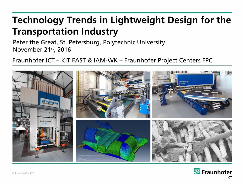
Technology Trends in Lightweight Design for the Transportation Industry
Fraunhofer ICT – KIT FAST & IAM-WK – Fraunhofer Project Centers FPC
Peter the Great, St. Petersburg, Polytechnic UniversityNovember 21st, 2016
© Fraunhofer ICT
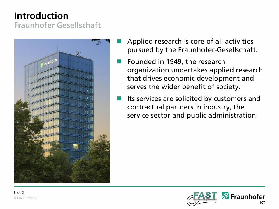
Applied research is core of all activities pursued by the Fraunhofer-Gesellschaft.
Founded in 1949, the research organization undertakes applied research that drives economic development and serves the wider benefit of society.
Its services are solicited by customers and contractual partners in industry, the service sector and public administration.
IntroductionFraunhofer Gesellschaft
Page 2

© Fraunhofer ICT
Slide 3
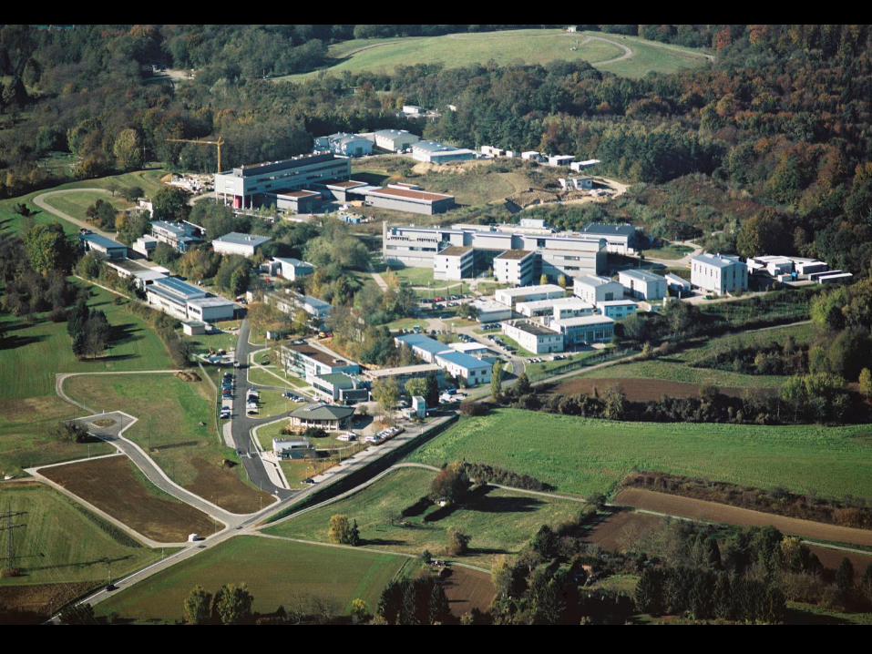
Founded in 1949 in Munich
66 institutes and research units in
Germany
More than 24,000 employees
Annual budget is about € 2,2 billion,
partly public founded
Representative offices, research units,
and subsidiaries worldwide
The Fraunhofer-GesellschaftMain locations of the Fraunhofer institutes and research institutions in Germany
Main sites
Other sites
Fraunhofer ICTPfinztal
© Fraunhofer ICT
Slide 4
© Fraunhofer ICT

© Fraunhofer ICT
Slide 5
Organization chart of the Fraunhofer ICT
Energetic Materials
Dr. H. KrauseDr. T. KeicherDr. S. Löbbecke
EnergeticSystems
W. EcklG. LangerDr. J. Neutz
Applied Electrochemistry
Dr. J. TübkeDr. K. Pinkwart
Environmental Engineering
R. SchweppeS. Rühle
Polymer Engineering
Prof. Dr. F. HenningDr. J. DiemertDr. T. Huber
Administration
Dr. B. Hefer, C. Steuerwald
General Management
Dr. S. Tröster
Institute Director
Prof. Dr. P. Elsner
Deputy Directors
Dr. H. Krause, Prof. Dr. F. Henning
Controlling
C. Steuerwald
Project Group for Sustainable MobilityFH Braunschweig-Wolfenbüttel, WolfsburgDr. J. Tübke
Project Group for New Drive Systems NAS, KarlsruheDr. H.-P. Kollmeier, Prof. Dr. P. Elsner, Prof. Dr. P. Gumbsch (IWM)
Fraunhofer Project Center FPC UNIST (Ulsan, Korea)Prof. Dr. F. Henning, Prof. Young-Bin Park
Fraunhofer Project Center FPC London (Ontario, Canada)Prof. Dr. F. Henning, V. Ugresic
Fraunhofer ICT-IMM, MainzProf. Dr. Michael Maskos

© Fraunhofer ICT
Slide 6
National and International NetworkExtended Research Activities
Access to key markets
R&D network
Student exchanges
Graduate schools
FPC@UNISTFPC@Western
USA &Canada
Europe
Asia

© Fraunhofer ICT 7
Railed vehicles: aluminum is the dominating material, however HSS shows a
growth of 14 %
25.11.2016
Market for railed vehicles sectorMarket volumein bn €
MMC
FRP
Aluminium
Steel (high strength)
Plastics
© Fraunhofer ICT 8
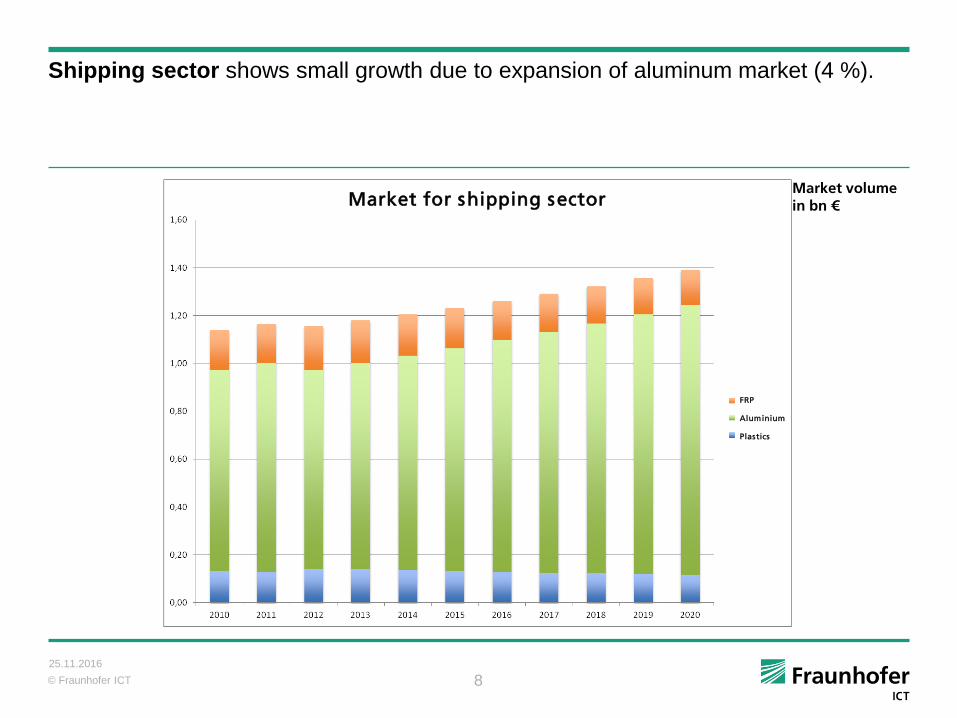
Shipping sector shows small growth due to expansion of aluminum market (4 %).
25.11.2016
Market volumein bn €
FRP
Aluminium
Plastics
Market for shipping sectorMarket for shipping sector

© Fraunhofer ICT 9
Main lightweight-materials for the aerospace sector are aluminum (1,7 % growth),
titanium (13% growth) and composites (15 %). Magnesium might also become
important in the future (30 %).
25.11.2016
Market volumein bn €
MMC
FRP
Titan
Magnesium
Aluminium
Plastics
Market for aerospace sector

© Fraunhofer ICT
Weight Reduction of Airplanes
Source: Prof. Dr.-Ing. Klaus Drechsler
Page 10

© Fraunhofer ICT
University Paderborn/ Tröster
50
100
150
0,15 0,3 0,45W
eig
htre
du
ction
[kg
]
Reduction of fuel consumption [l/100 km]
Reduction of CO2-Emissions [g CO2/km]
8,54,3 12,8
BMW 7er
VW Golf
VW 1- Literauto
VW Lupo
Opel Corsa
Opel Omega
Increase of vehicle mass within 50 years
Year
Weig
ht
© Fraunhofer ICT 12
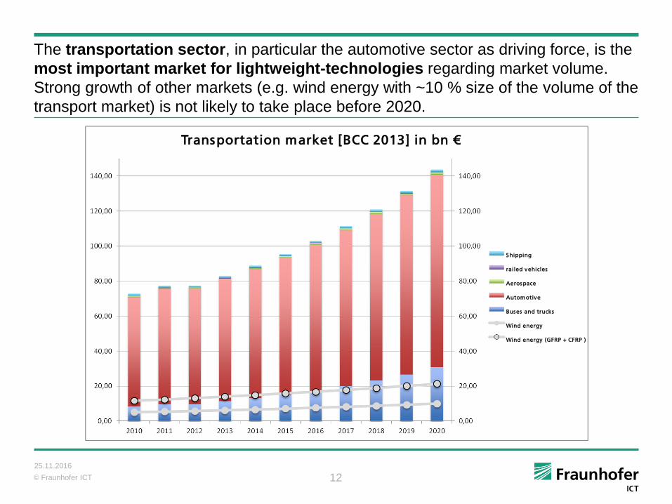
The transportation sector, in particular the automotive sector as driving force, is the
most important market for lightweight-technologies regarding market volume.
Strong growth of other markets (e.g. wind energy with ~10 % size of the volume of the
transport market) is not likely to take place before 2020.
25.11.2016
Transportation market [BCC 2013] in bn €
Shipping
railed vehicles
Aerospace
Automotive
Buses and trucks
Wind energy
Wind energy (GFRP + CFRP )
© Fraunhofer ICT 13
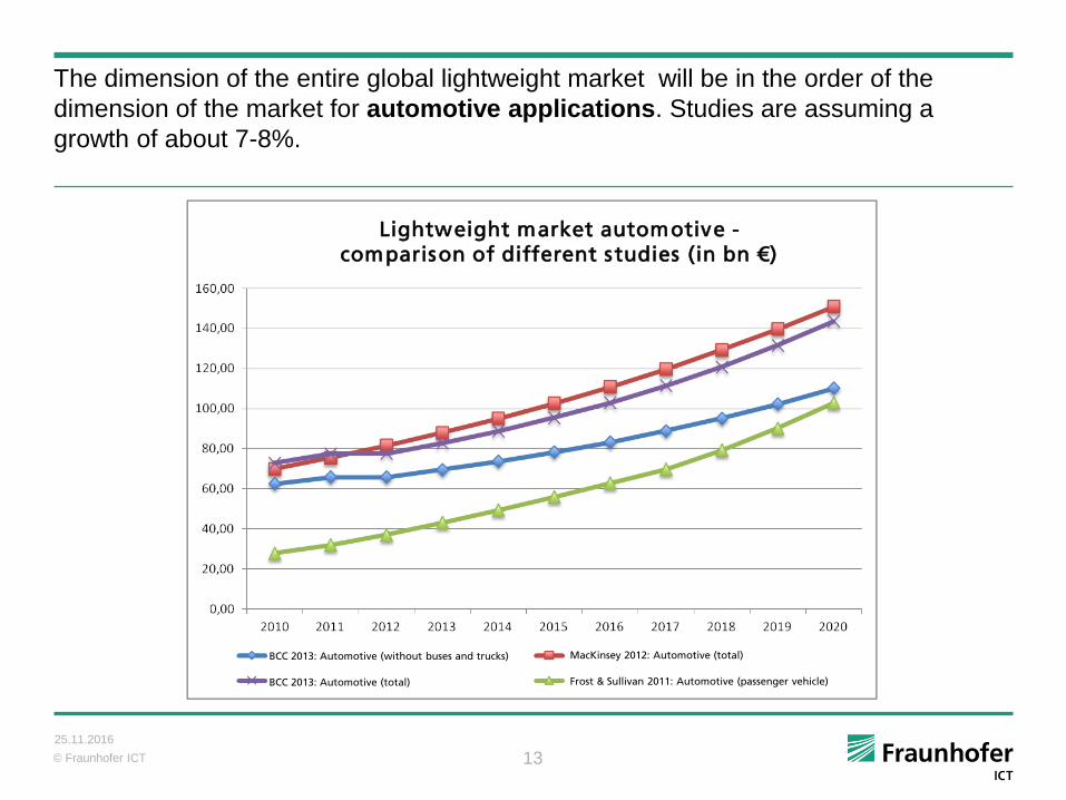
The dimension of the entire global lightweight market will be in the order of the
dimension of the market for automotive applications. Studies are assuming a
growth of about 7-8%.
25.11.2016
Lightweight market automotive -comparison of different studies (in bn €)
BCC 2013: Automotive (without buses and trucks)
BCC 2013: Automotive (total)
MacKinsey 2012: Automotive (total)
Frost & Sullivan 2011: Automotive (passenger vehicle)

© Fraunhofer ICT
Forel Study - Accepted Costs for Lightweight Design
1425.11.2016
Source: Forel Studie -2015
automotive sector
with conventional engine
automotive sector
with electric drive
aerospace
aerospace – outer space
up to 7
up to 18
up to 500
up to 3000

© Fraunhofer ICT
Lightweight design is mainly established in the transportation sector.
Automotive industry is most important; Utility vehicles (buses and trucks) show strong growth
Other markets, e.g. wind energy, nowadays of lower importance but with a strongly
increasing tendency emerging markets
Lightweight design based on metals is and will be the main market in automotive until
approx. 2020
High-strength-steel shows highest growth rate in automotive; Magnesium shows growth rate as
well but based on a much lower market size emerging market
Plastics show constant but intermediate growth rate
Composites show very high growth rate and will most likely be of increased importance
in the long term (2020 and later) cost as main challenge
In the long term increasing trend towards hybrid lightweight design
Conclusion Market Trends Analysis
1525.11.2016
© Fraunhofer ICT
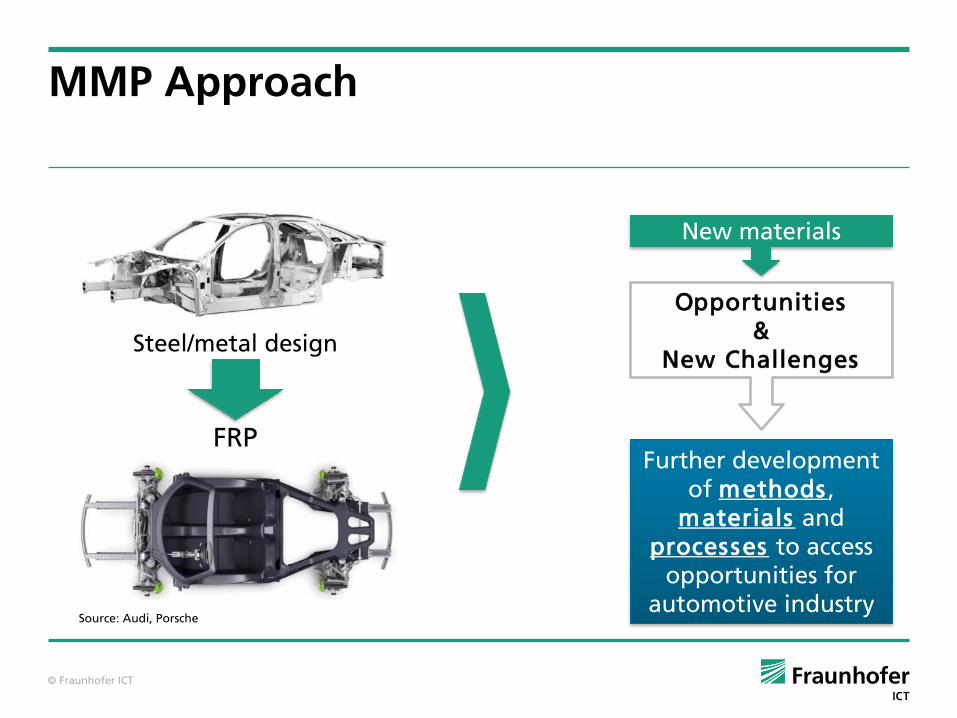
Steel/metal design
FRP
MMP Approach
Source: Audi, Porsche
Opportunities&
New Challenges
New materials
Further development of methods ,
materials and processes to access
opportunities for automotive industry

© Fraunhofer ICT
Slide 17
MMP Approach
Component performance Economics
A R E A S O F I N T E R A C T I O N
QUALITY
TIME
COSTS
PROCESSES
METHODS
MATERIALSS Y S T E M E F F I C I E N T
L I G H T W E I G H T D E S I G N
MMP-Approach
© Fraunhofer ICT
Slide 18
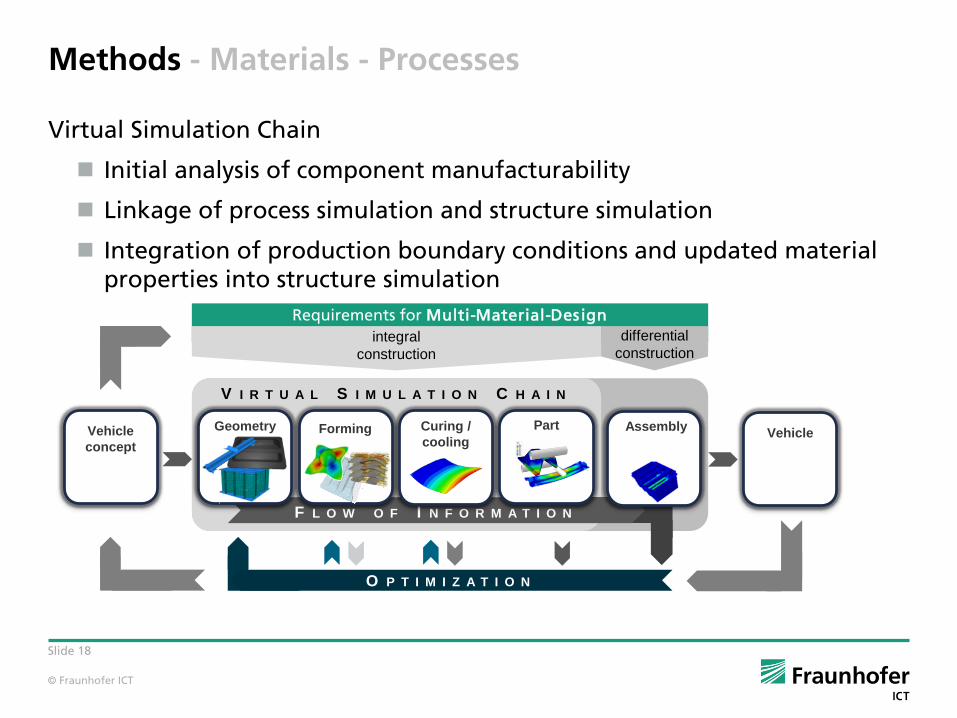
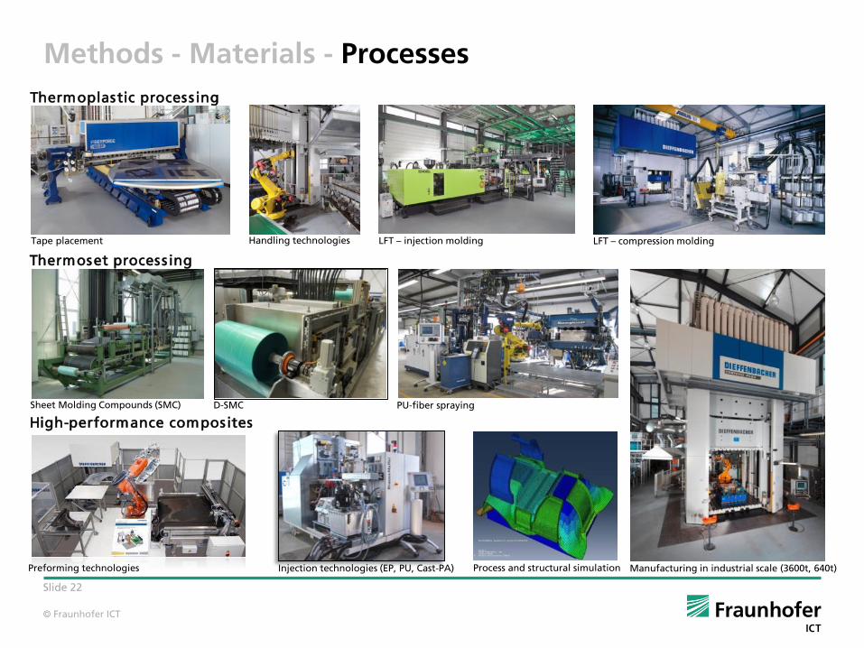
Methods - Materials - Processes
Virtual Simulation Chain
Initial analysis of component manufacturability
Linkage of process simulation and structure simulation
Integration of production boundary conditions and updated material properties into structure simulation
Requirements for Multi-Material-Design
V I R T U A L S I M U L A T I O N C H A I N
F L O W O F I N F O R M A T I O N
O P T I M I Z A T I O N
Geometry Forming Curing /
cooling
Part Assembly
integral
construction
differential
construction
Vehicle
conceptVehicle

© Fraunhofer ICT
Slide 19
KIT Institute of Vehicle System Technology –Lightweight technology FAST
Process simulation
Optimization of cycle times for manufacturing of composite components
Evaluation and improvement of process control and machinery
Dissemination of relevant material and process information on structural simulation (within the context of CAE-chain, e.g. fiber orientation, fiber volume content, porosity)
Structural simulation
Simulation of deformation and failure behavior of composite structures
Investigation of the influence of manufacturing effects on the component behavior
Consideration of production factors to increase the prediction accuracy (integration in the CAE-chain)
Further development of models and methods for hybridization
© Fraunhofer ICT
Slide 20
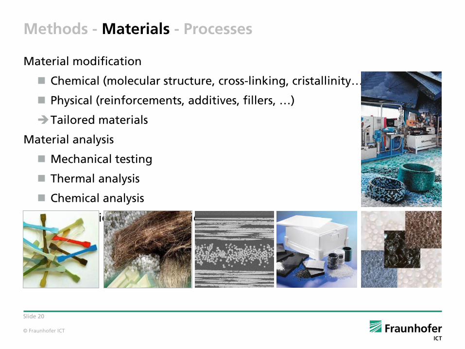
Methods - Materials - Processes
Material modification
Chemical (molecular structure, cross-linking, cristallinity…)
Physical (reinforcements, additives, fillers, …)
Tailored materials
Material analysis
Mechanical testing
Thermal analysis
Chemical analysis
Morphological characterization
© Fraunhofer ICT
Slide 21
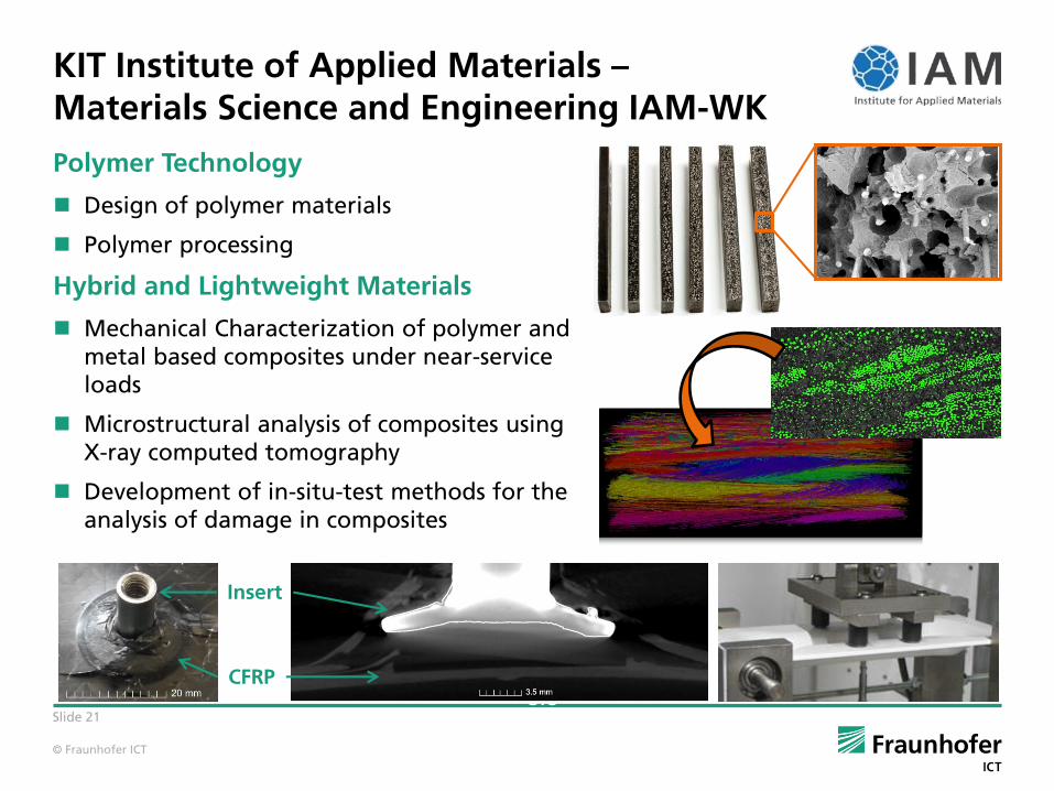
KIT Institute of Applied Materials –Materials Science and Engineering IAM-WK
Polymer Technology
Design of polymer materials
Polymer processing
Hybrid and Lightweight Materials
Mechanical Characterization of polymer and metal based composites under near-service loads
Microstructural analysis of composites usingX-ray computed tomography
Development of in-situ-test methods for the analysis of damage in composites
1 m
m in
thro
ug
h-
thic
kn
ess d
irectio
n C
Visualization of in-plane orientation 1200 x 750 x 400 Voxel
B
A
B
3.5
m
m
CFRP
Insert
© Fraunhofer ICT
Slide 22
Thermoplastic process ing
Thermoset process ing
High-performance composites
Preforming technologies Injection technologies (EP, PU, Cast-PA) Process and structural simulation Manufacturing in industrial scale (3600t, 640t)
D-SMCSheet Molding Compounds (SMC) PU-fiber spraying
Tape placement LFT – injection molding LFT – compression moldingHandling technologies
Methods - Materials - Processes
© Fraunhofer ICT
Slide 23
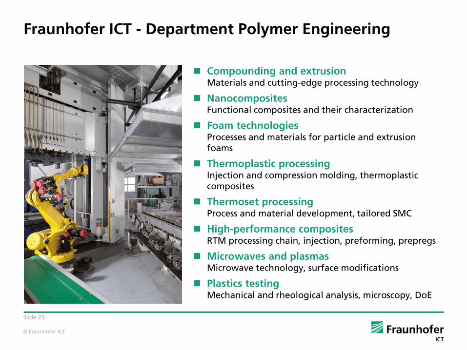
Fraunhofer ICT - Department Polymer Engineering
Compounding and extrusionMaterials and cutting-edge processing technology
NanocompositesFunctional composites and their characterization
Foam technologiesProcesses and materials for particle and extrusion foams
Thermoplastic processingInjection and compression molding, thermoplastic composites
Thermoset processingProcess and material development, tailored SMC
High-performance compositesRTM processing chain, injection, preforming, prepregs
Microwaves and plasmasMicrowave technology, surface modifications
Plastics testingMechanical and rheological analysis, microscopy, DoE

© Fraunhofer ICT
Slide 24
Braiding*1
Overview of process technologies
*1Continuous-fiber preform
Braiding*1

© Fraunhofer ICT
Slide 25
Thermoplastic composites-
Discontinuous fiber reinforcement
© Fraunhofer ICT
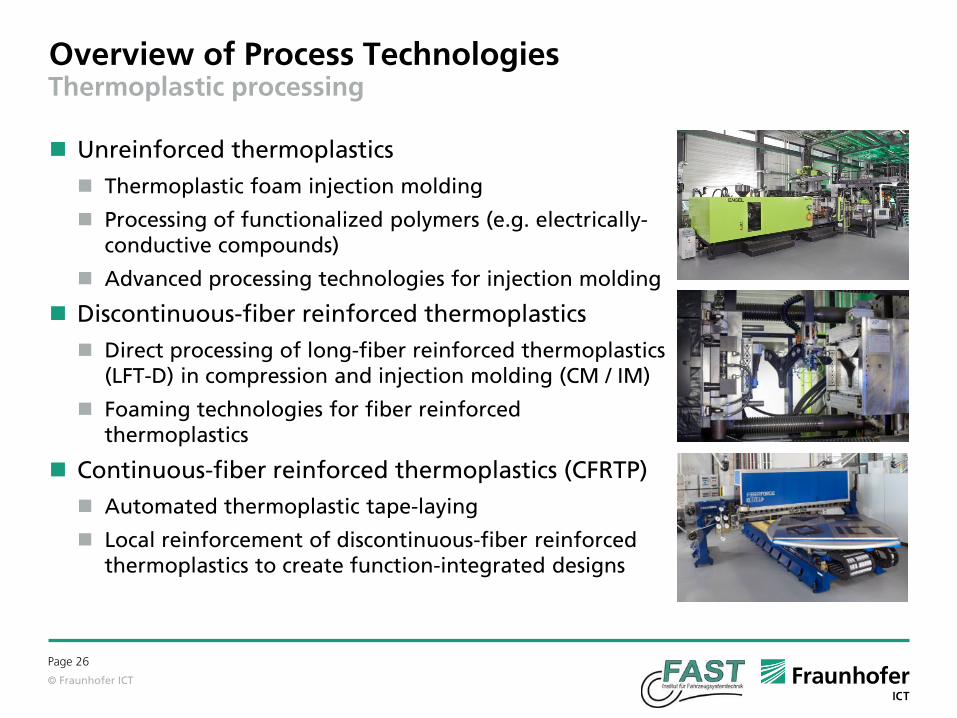
Overview of Process Technologies
Page 26
Thermoplastic processing
Unreinforced thermoplastics
Thermoplastic foam injection molding
Processing of functionalized polymers (e.g. electrically-conductive compounds)
Advanced processing technologies for injection molding
Discontinuous-fiber reinforced thermoplastics
Direct processing of long-fiber reinforced thermoplastics (LFT-D) in compression and injection molding (CM / IM)
Foaming technologies for fiber reinforcedthermoplastics
Continuous-fiber reinforced thermoplastics (CFRTP)
Automated thermoplastic tape-laying
Local reinforcement of discontinuous-fiber reinforced thermoplastics to create function-integrated designs

© Fraunhofer ICT
Slide 27
Discontinuous-fiber reinforced thermoplastics Typical applications of LFT
Thermoplastic composites with discontinuous-fiber reinforcement are already a well-established engineering material for semi-structural applications with constant growing market share
Frontend-module Golf VII; PA6/LGF
Source: BASF/VW
Seat structure BMW I3;PA6/LGF
Source: BASF/BMW
Instrument panel Ford Escape/Kuga; PP/LGF
Source: Faurecia/Sabic
Oil tray Actros;PA6.6/GF35
Source: Lanxess/Daimler
Gear carrier BMW 5er GT; PA6/GF
Source: ContiTech/BASF
Under body shield;PP/GF
Source: Polytec/VW
© Fraunhofer ICT
Slide 28
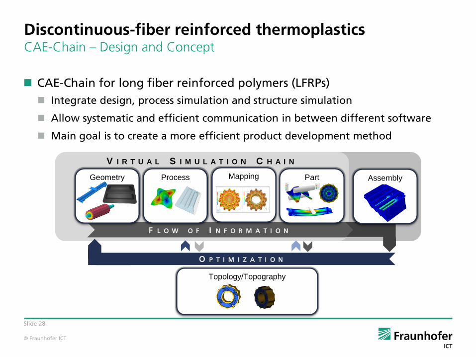
Discontinuous-fiber reinforced thermoplastics CAE-Chain – Design and Concept
CAE-Chain for long fiber reinforced polymers (LFRPs)
Integrate design, process simulation and structure simulation
Allow systematic and efficient communication in between different software
Main goal is to create a more efficient product development method
V I R T U A L S I M U L A T I O N C H A I N
F L O W O F I N F O R M A T I O N
O P T I M I Z A T I O N
Process AssemblyPartGeometry
Topology/Topography
Mapping
© Fraunhofer ICT
Slide 29
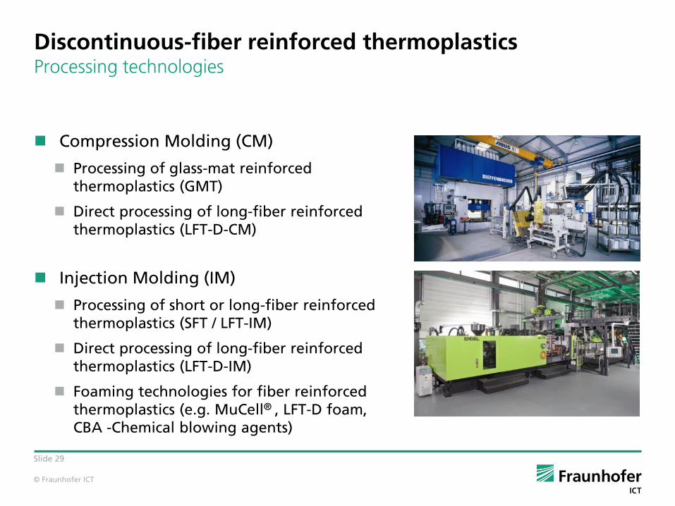
Discontinuous-fiber reinforced thermoplastics Processing technologies
Compression Molding (CM)
Processing of glass-mat reinforcedthermoplastics (GMT)
Direct processing of long-fiber reinforced thermoplastics (LFT-D-CM)
Injection Molding (IM)
Processing of short or long-fiber reinforced thermoplastics (SFT / LFT-IM)
Direct processing of long-fiber reinforced thermoplastics (LFT-D-IM)
Foaming technologies for fiber reinforcedthermoplastics (e.g. MuCell® , LFT-D foam,CBA -Chemical blowing agents)

© Fraunhofer ICT
Slide 30
Discontinuous-fiber reinforced thermoplastics Principle of direct compounding of LFT in compression molding (LFT-D-CM)
LFT plastificate(open transfer)
Inline Compounder Natural
…
Reinforcing fibers :
Carbon
Glass
Matrix res ins :
Commodity Thermoplastics
Engineering Thermoplastics
Blends
…
Further developments in LFT-D-CM
Use of technical thermoplastics as matrix material (e.g. PPS, PEEK…)
Combination with continuous-fiber reinforcements
Compression molding
Mixing Extruder with die
Polymer + Additives
© Fraunhofer ICT
Slide 31
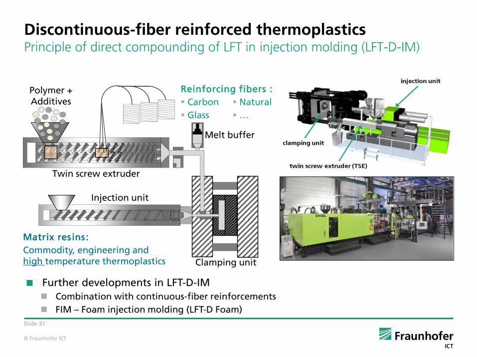
Discontinuous-fiber reinforced thermoplastics Principle of direct compounding of LFT in injection molding (LFT-D-IM)
Matrix res ins :
Commodity, engineering and high temperature thermoplastics
Further developments in LFT-D-IM
Combination with continuous-fiber reinforcements
FIM – Foam injection molding (LFT-D Foam)
Twin screw extruder
Polymer + Additives
Injection unit
Melt buffer
Clamping unit
Natural
…
Reinforcing fibers :
Carbon
Glass
© Fraunhofer ICT
Slide 32
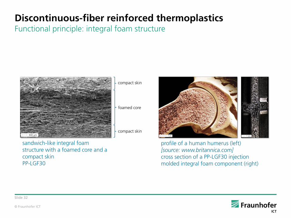
Discontinuous-fiber reinforced thermoplasticsFunctional principle: integral foam structure
1 cm 1 mm
profile of a human humerus (left) [source: www.britannica.com]cross section of a PP-LGF30 injection molded integral foam component (right)
Kompakte Außenhaut
Schaumkern
Kompakte Außenhaut
300 µm
sandwich-like integral foam structure with a foamed core and a compact skinPP-LGF30
compact skin
compact skin
foamed core
© Fraunhofer ICT
Slide 33
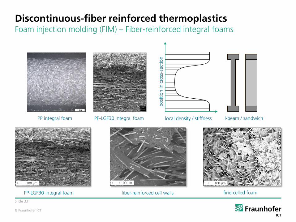
Discontinuous-fiber reinforced thermoplasticsFoam injection molding (FIM) – Fiber-reinforced integral foams
PP integral foam PP-LGF30 integral foam local density / stiffness I-beam / sandwich
po
sition in
cro
ss-s
ectio
n
300 µm300 µm 100 µm100 µm
PP-LGF30 integral foam fiber-reinforced cell walls fine-celled foam

© Fraunhofer ICT
Slide 34
Discontinuous-fiber reinforced thermoplasticsLFT-Foams – Lightweight potential of the Breathing mold
CBAMuCell
LFT-D-Foam
increasing• wall thickness• density reduction• bending stiffness
delay timemold breathing
0,0
1,0
2,0
3,0
3,5 4,0 4,5 5,0 5,5 6,0
rela
tive
bendin
g s
tiff
ness
[ ]
wall thickness [mm]
PP-LGF30 CBA
PP-LGF30 MuCell
PP-LGF30 LFT-D
SB = EB ∙ Iy = EB ∙b∙h3
12
stronglyincreasing
slightlydecreasing

© Fraunhofer ICT
Slide 35
Thermoplastic composites-
Continuous fiber reinforcement
© Fraunhofer ICT
Slide 36
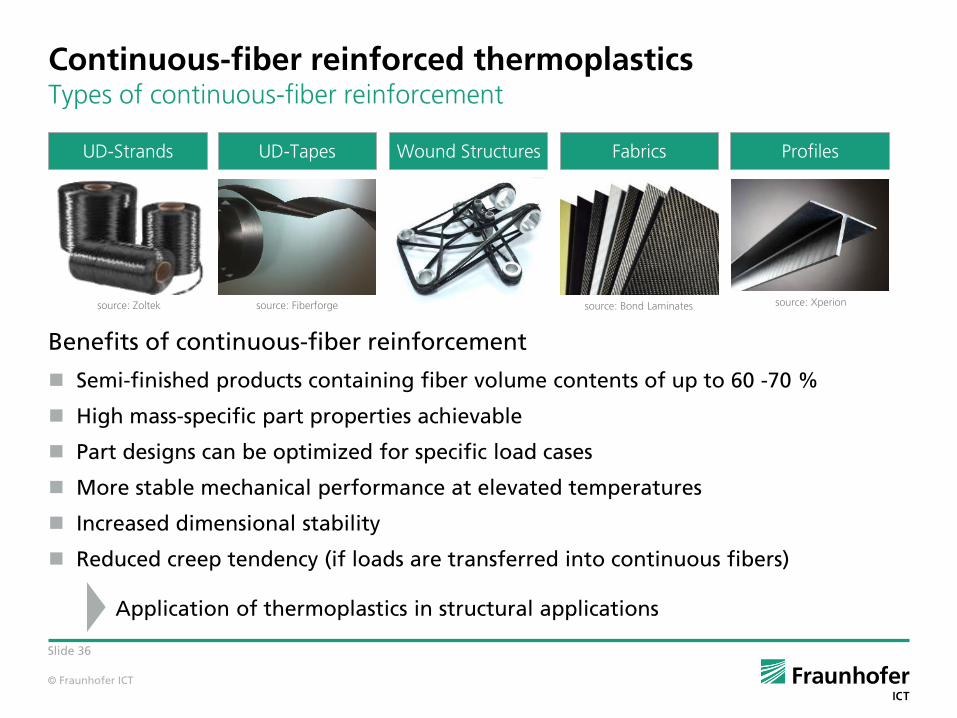
Continuous-fiber reinforced thermoplasticsTypes of continuous-fiber reinforcement
Benefits of continuous-fiber reinforcement
Semi-finished products containing fiber volume contents of up to 60 -70 %
High mass-specific part properties achievable
Part designs can be optimized for specific load cases
More stable mechanical performance at elevated temperatures
Increased dimensional stability
Reduced creep tendency (if loads are transferred into continuous fibers)
Application of thermoplastics in structural applications
UD-Tapes Wound Structures FabricsUD-Strands Profiles
source: Bond Laminatessource: Fiberforgesource: Zoltek source: Xperion
© Fraunhofer ICT
Slide 37
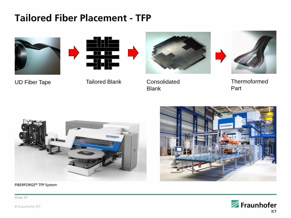
Tailored Fiber Placement - TFP
FIBERFORGE® TFP System
UD Fiber Tape Tailored Blank Consolidated
Blank
Thermoformed
Part
© Fraunhofer ICT
Slide 38
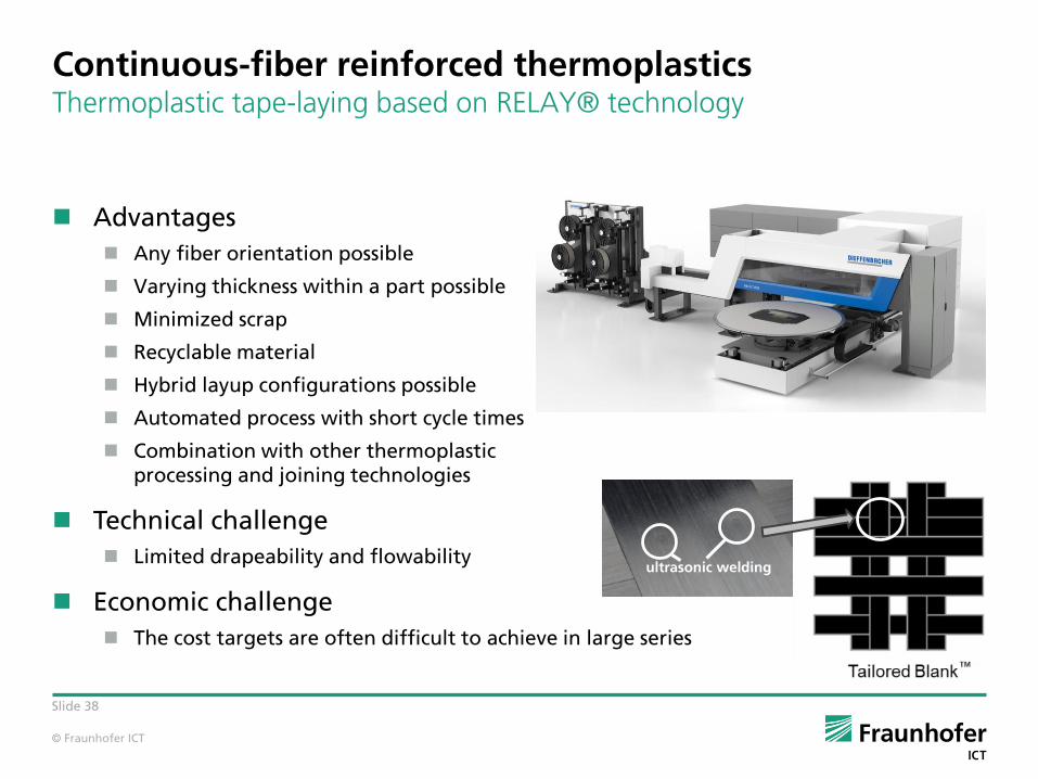
Continuous-fiber reinforced thermoplasticsThermoplastic tape-laying based on RELAY® technology
Advantages
Any fiber orientation possible
Varying thickness within a part possible
Minimized scrap
Recyclable material
Hybrid layup configurations possible
Automated process with short cycle times
Combination with other thermoplastic processing and joining technologies
Technical challenge
Limited drapeability and flowability
Economic challenge
The cost targets are often difficult to achieve in large series
ultrasonic welding
© Fraunhofer ICT
Slide 39
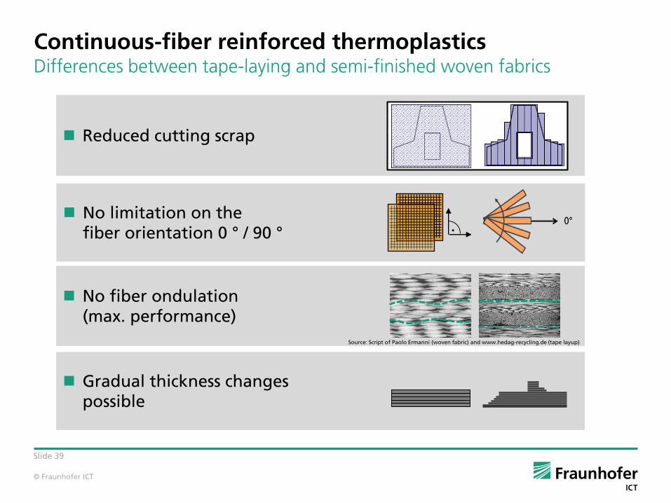
Continuous-fiber reinforced thermoplasticsDifferences between tape-laying and semi-finished woven fabrics
No fiber ondulation(max. performance)
Reduced cutting scrap
No limitation on the fiber orientation 0 ° / 90 °
Gradual thickness changespossible
Source: Script of Paolo Ermanni (woven fabric) and www.hedag-recycling.de (tape layup)
.

© Fraunhofer ICT
Slide 40
Continuous-fiber reinforced thermoplastics CAE-Chain – Design and Concept
Main focus: Virtual Representation of the Continuous Virtual Process Chain
virtually combine design, manufacturing and structural validation
Requirements for Multi-Material-Design
V I R T U A L P R O C E S S C H A I N
F L O W O F I N F O R M A T I O N
O P T I M I Z A T I O N
Molding Cooling Part Assembly
integral constructiondifferential construction
Geometry Forming
© Fraunhofer ICT
Slide 41
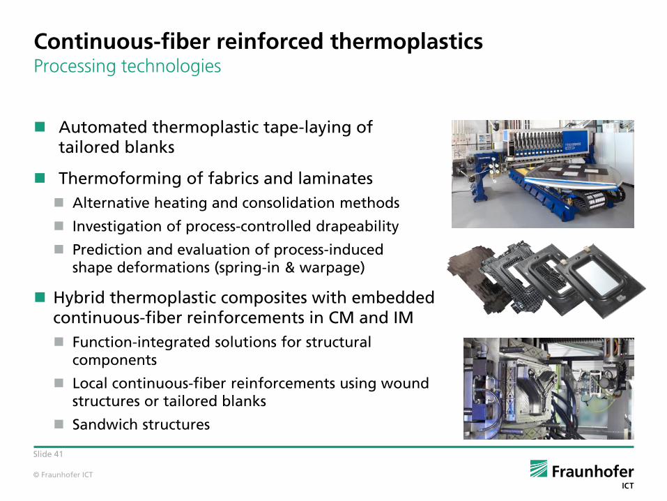
Continuous-fiber reinforced thermoplastics Processing technologies
Automated thermoplastic tape-laying of tailored blanks
Thermoforming of fabrics and laminates
Alternative heating and consolidation methods
Investigation of process-controlled drapeability
Prediction and evaluation of process-inducedshape deformations (spring-in & warpage)
Hybrid thermoplastic composites with embedded continuous-fiber reinforcements in CM and IM
Function-integrated solutions for structural components
Local continuous-fiber reinforcements using wound structures or tailored blanks
Sandwich structures

© Fraunhofer ICT
Fiberforge 4.0 – Machine Architecture
42
Spool Unwinding
Cutter
24 US-Welders Lay-up beam
Motion Table
Tape Tensioning
Tape Toogle
Rotation Axis
X- Axis

© Fraunhofer ICT
Fiberforge 4.0 - Improvements
43
Productivity
Fiberforge 4.0 is 3.5 times faster than Fiberforge Relay 2000
Continuous tape supply to lay-up system – no downtime due to reloading of spools
Cycle time of less than 1s per tape at maximum tape length of 2000mm;
including spot welding
Two shorter tapes (e.g. 300mm + 500mm) can be placed in a row
with same cycle time of less than 1s
Performance example
Glass fiber tapes (PP/GF60), with 0,25mm thickness + 165mm width +
average tape length of 1500mm results in a production capacity of 368 kg/h
Carbon fiber tapes (PA/CF55), with 0,16mm thickness + 165mm width +
average tape length of 1500mm results in a production capacity of 208 kg/h
© Fraunhofer ICT
Fiberforge 4.0 - Improvements
44
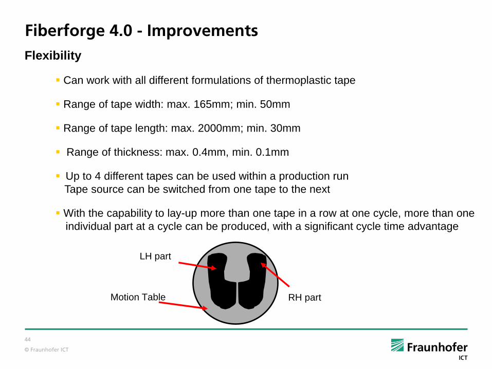
Flexibility
Can work with all different formulations of thermoplastic tape
Range of tape width: max. 165mm; min. 50mm
Range of tape length: max. 2000mm; min. 30mm
Range of thickness: max. 0.4mm, min. 0.1mm
Up to 4 different tapes can be used within a production run
Tape source can be switched from one tape to the next
With the capability to lay-up more than one tape in a row at one cycle, more than one
individual part at a cycle can be produced, with a significant cycle time advantage
RH partMotion Table
LH part
© Fraunhofer ICT
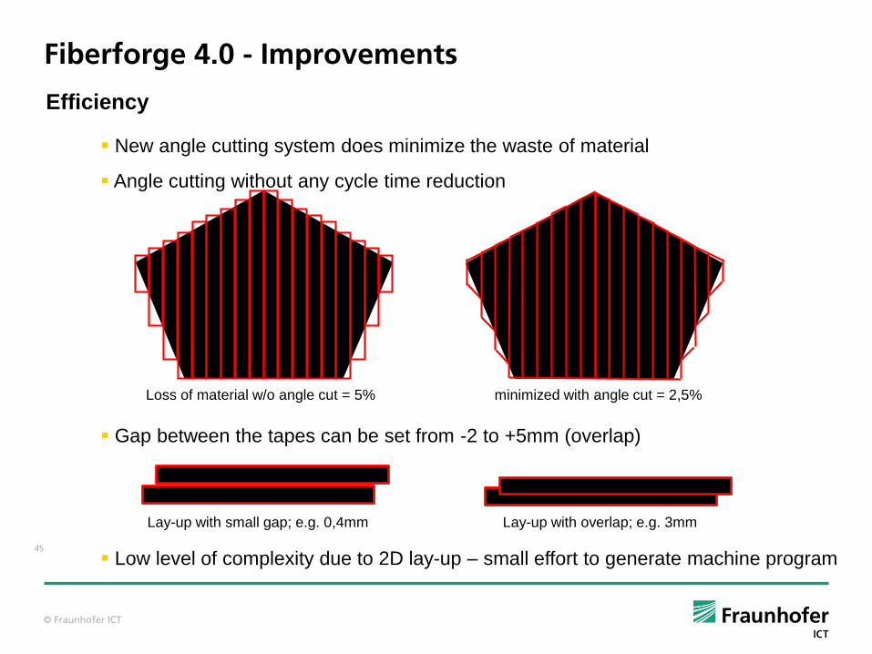
Fiberforge 4.0 - Improvements
45
Efficiency
New angle cutting system does minimize the waste of material
Angle cutting without any cycle time reduction
Loss of material w/o angle cut = 5% minimized with angle cut = 2,5%
Gap between the tapes can be set from -2 to +5mm (overlap)
Lay-up with small gap; e.g. 0,4mm Lay-up with overlap; e.g. 3mm
Low level of complexity due to 2D lay-up – small effort to generate machine program

© Fraunhofer ICT
46
Precision
High accuracy and repeatability
Constant gap between the tapes within a layup
Machine repeatability: C = 0.01°; Y = 0.25 mm; U = 2.0 mm (U is the tape feed axis)
Machine resolution: C = 0.005°; X, Y = 0.03 mm; U = 0.1 mm
Fiberforge 4.0 – Improvements / Applications
Applications
- Seat structures - Load Compartment
- Battery compartment - Floor pan
- Door inner - Hood, roof and tail-gate structural reinforcement
- Bumper beam - Fire wall
- Local reinforced front end carrier and underbody shielding

© Fraunhofer ICT
Slide 47
Continuous-fiber reinforced thermoplasticsDevelopment of consolidation process technologies
Consolidation Process- based on hydraulic presses (HTP)- based on vacuum technology
(fast out-of-autoclave process)
Tailored-blank(Consolidated)
Composite PartTailored-blankUD Tape
© Fraunhofer ICT
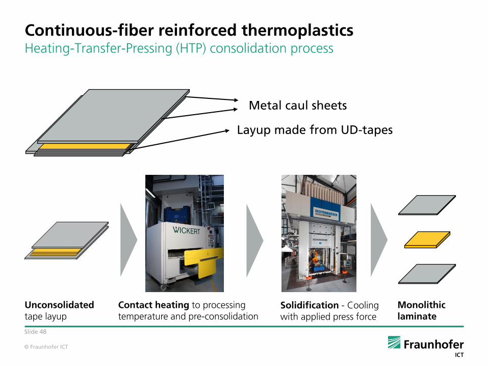
Slide 48
Continuous-fiber reinforced thermoplasticsHeating-Transfer-Pressing (HTP) consolidation process
Metal caul sheets
Layup made from UD-tapes
Unconsolidatedtape layup
Contact heating to processingtemperature and pre-consolidation
Solidification - Coolingwith applied press force
Monolithiclaminate
© Fraunhofer ICT
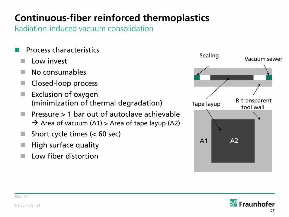
Slide 49
Process characteristics
Low invest
No consumables
Closed-loop process
Exclusion of oxygen(minimization of thermal degradation)
Pressure > 1 bar out of autoclave achievable Area of vacuum (A1) > Area of tape layup (A2)
Short cycle times (< 60 sec)
High surface quality
Low fiber distortion
SealingVacuum sewer
Tape layupIR-transparent
tool wall
A1 A2
Continuous-fiber reinforced thermoplasticsRadiation-induced vacuum consolidation

© Fraunhofer ICT
Slide 50
C-Scan CT
Po
or
Qu
ali
tyG
oo
dQ
ua
lity
SEM
Mechanical analysis
Optical analysis
Continuous-fiber reinforced thermoplasticsAnalysis of consolidation quality
Execution AnalysisDefinition

© Fraunhofer ICT
Slide 51
Continuous-fiber reinforced thermoplasticsLaminate forming in context of the MMP approach
M E T H O D S
Process realization
Process characterization
Process monitoring
P R O C E S S E S M A T E R I A L S
Process Simulation
Model development
Part validation
Customized testing set ups
CAE chain approach
Mechanical & morphological characterization- data interpretation- link to M & P
© Fraunhofer ICT
Slide 52
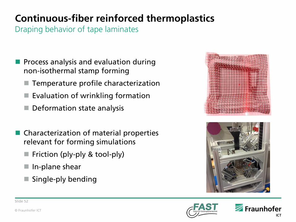
Continuous-fiber reinforced thermoplastics Draping behavior of tape laminates
Process analysis and evaluation duringnon-isothermal stamp forming
Temperature profile characterization
Evaluation of wrinkling formation
Deformation state analysis
Characterization of material propertiesrelevant for forming simulations
Friction (ply-ply & tool-ply)
In-plane shear
Single-ply bending

© Fraunhofer ICT
Slide 53
PPS/CF laminate with 12 layers (~ 1.8 mm)
Forming ends well before recrystallization of the material
Continuous-fiber reinforced thermoplasticsTemperature profile during non-isothermal stamp forming

© Fraunhofer ICT
Slide 54
Continuous-fiber reinforced thermoplastics Quantification of wrinkles during stamp forming
Evolution of wrinkles during forming (experimental results for PPS/CF)
Source:T. Joppich, D. Dörr, et. al. “Layup and Process Dependent Behavior of PPS/CF UD Tape-Laminates during Non-Isothermal Press Forming Into a Complex Component ,” proceedings from ESAFORM Conference, Nantes, 2016
© Fraunhofer ICT
Slide 55
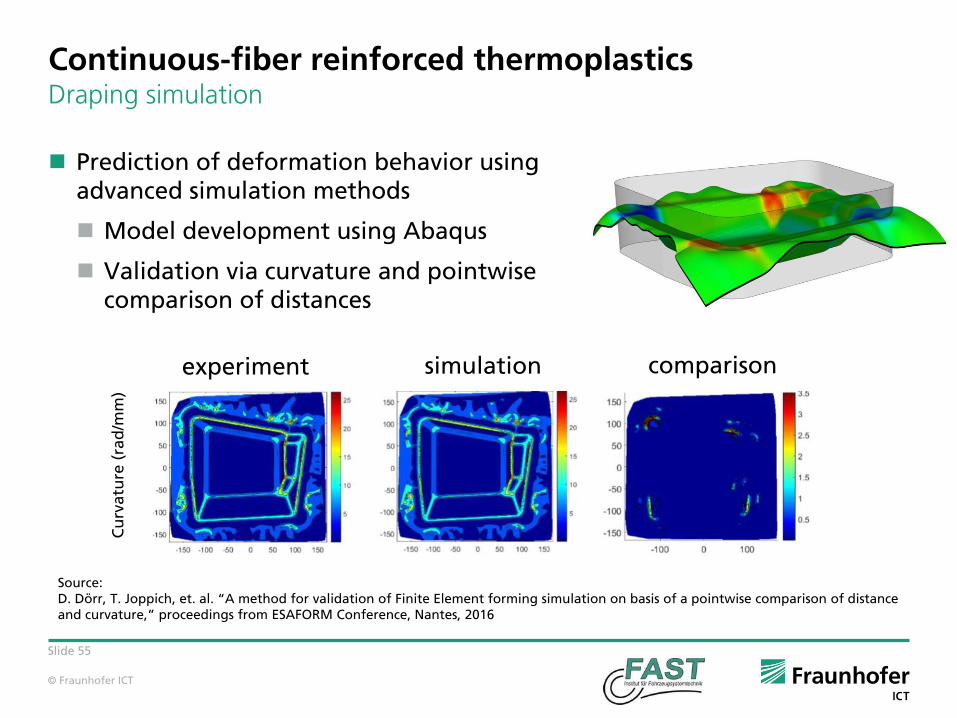
Continuous-fiber reinforced thermoplastics Draping simulation
Prediction of deformation behavior usingadvanced simulation methods
Model development using Abaqus
Validation via curvature and pointwisecomparison of distances
experiment simulation comparison
Cu
rva
ture
(ra
d/m
m)
Source:D. Dörr, T. Joppich, et. al. “A method for validation of Finite Element forming simulation on basis of a pointwise comparison of distanceand curvature,” proceedings from ESAFORM Conference, Nantes, 2016
© Fraunhofer ICT
Slide 56
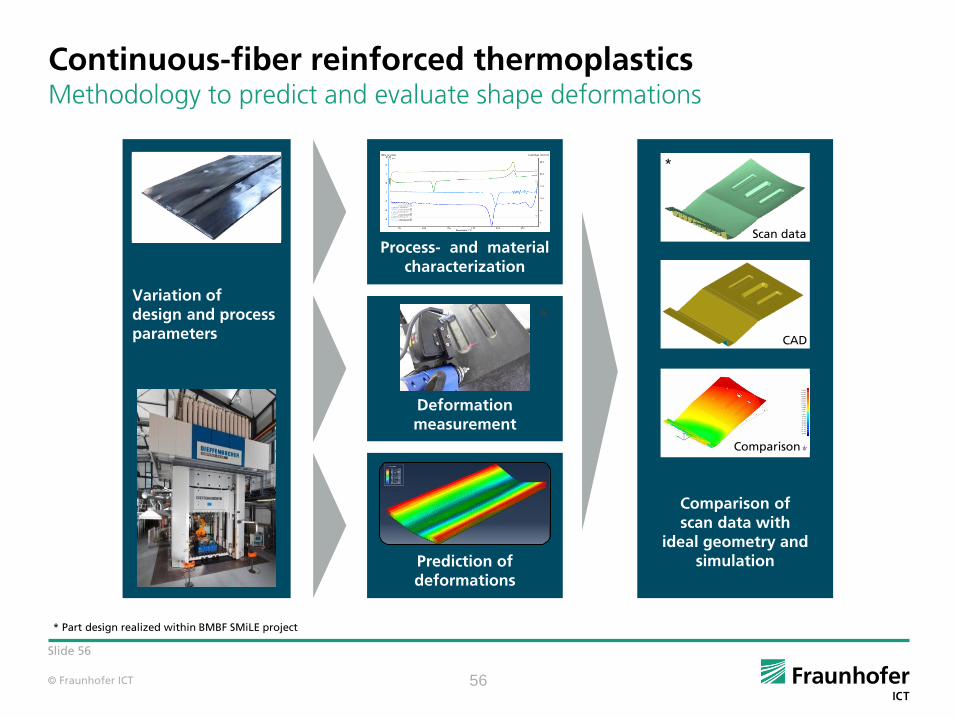
Continuous-fiber reinforced thermoplasticsMethodology to predict and evaluate shape deformations
56
Process- and material characterization
Variation ofdesign and processparameters
Deformation measurement
Prediction ofdeformations
Comparison ofscan data with
ideal geometry andsimulation
*
Scan data
CAD
Comparison
*
* Part design realized within BMBF SMiLE project

© Fraunhofer ICT
Slide 57
Variation of design and process parameters
Processing parts with different layups
Manufacturing of various part geometries
Application of different press forces and tool temperatures
Hybridization by combining long-fiber reinforced thermoplastics withunidirectional tape
Continuous-fiber reinforced thermoplasticsMethodology to predict and evaluate shape deformations
* Part design realized within BMBF SMiLE project
*

© Fraunhofer ICT
Slide 58
Process and material characterization
Conducting studies with varying process parameter sets
Investigating the influence of processing routes
Mechanical and thermo-analytical material characterization
Holistic evaluation of process chains
Continuous-fiber reinforced thermoplasticsMethodology to predict and evaluate shape deformations
58
Recorded temperature profilesof a laminate‘s process cycle
DSC measurements of CF/PPS UD-tape
© Fraunhofer ICT
Slide 59
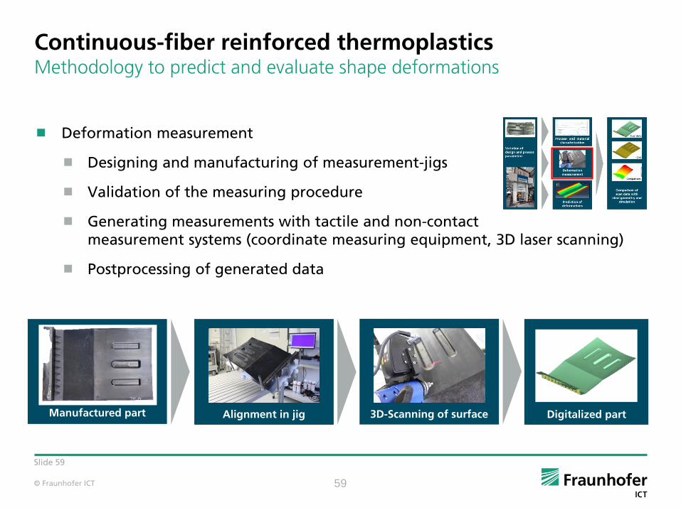
Deformation measurement
Designing and manufacturing of measurement-jigs
Validation of the measuring procedure
Generating measurements with tactile and non-contactmeasurement systems (coordinate measuring equipment, 3D laser scanning)
Postprocessing of generated data
Continuous-fiber reinforced thermoplasticsMethodology to predict and evaluate shape deformations
59
Manufactured part 3D-Scanning of surface Digitalized partAlignment in jig

© Fraunhofer ICT
Slide 60
Prediction of shape deformations
Simulation of a component‘s cooling behavior
Modelling the crystallization kinetics ofsemi-crystalline thermoplastics
Modelling of thermo-mechanical effects
Structural analysis to determine thermal stresses
Continuous-fiber reinforced thermoplasticsMethodology to predict and evaluate shape deformations
60
Crystallization kinetics of a CF/PPS compositePrediction of shape deformations
due to a local patch reinforcement
© Fraunhofer ICT
Slide 61
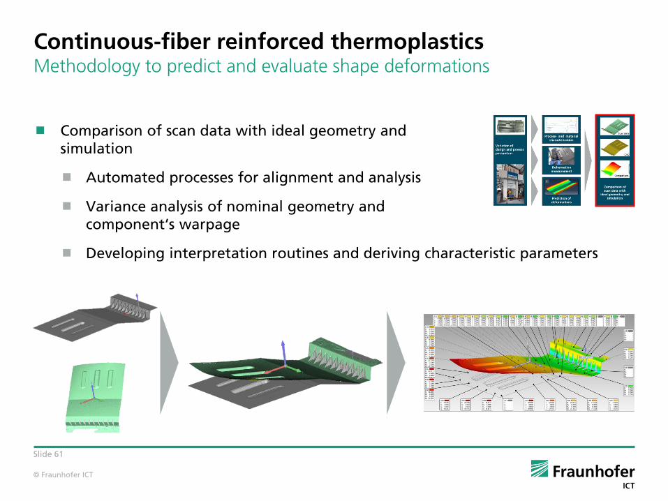
Comparison of scan data with ideal geometry andsimulation
Automated processes for alignment and analysis
Variance analysis of nominal geometry andcomponent‘s warpage
Developing interpretation routines and deriving characteristic parameters
Continuous-fiber reinforced thermoplasticsMethodology to predict and evaluate shape deformations

© Fraunhofer ICT
Slide 62
Continuous-fiber reinforced thermoplasticsHybrid thermoplastic composites
Combination of local continuous-fiber reinforcements and established high-volume process technologies
Compression (LFT-D-CM) and injection molding
(LFT-D-IM, LFT-G)
Local reinforcement with continuous fibers
Final composite parts
Component was realized within theMAI Carbon cluster
© Fraunhofer ICT
Slide 63
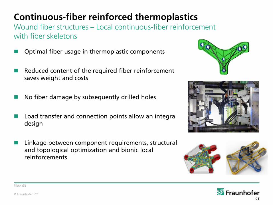
Continuous-fiber reinforced thermoplastics Wound fiber structures – Local continuous-fiber reinforcement with fiber skeletons
Optimal fiber usage in thermoplastic components
Reduced content of the required fiber reinforcement saves weight and costs
No fiber damage by subsequently drilled holes
Load transfer and connection points allow an integral design
Linkage between component requirements, structural and topological optimization and bionic local reinforcements
© Fraunhofer ICT
Slide 64
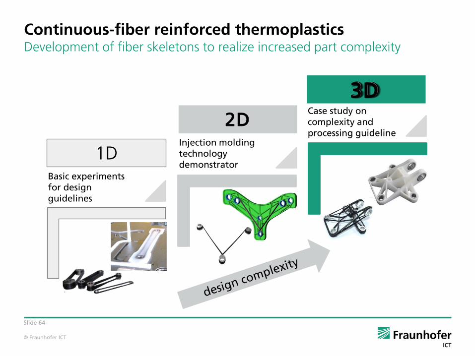
Continuous-fiber reinforced thermoplastics Development of fiber skeletons to realize increased part complexity
1D
2D
Basic experiments for design guidelines
Injection molding technology demonstrator
Case study on complexity and processing guideline
3D3D3D

© Fraunhofer ICT
Slide 65
Continuous-fiber reinforced thermoplastics Development route for locally reinforced components
Use of FEM simulation
Collision detection
Division into sub-loops
Use of force cone and primary point method
Winding of fiber skeleton
Overmolding of reinforcement structure
3. Verification of structure
4. Manufacturing feas ibility study
1. Definition of constraints
2. Identification of load paths
5. Production
Design space
Loads
Boundary conditions
F1
F2
From design space to optimized lightweight structure

© Fraunhofer ICT
Slide 66
From UD-tapes / fabrics to a passenger vehicle seat structure
Laminate optimization*
Tape-laying*
Pre-consolidation*
Trimming
In-mold-forming and
injection molding
*Process steps are necessary, if UD-tapes are used.
Continuous-fiber reinforced thermoplastics Case study: In-mold-forming an co-molding of a passenger vehicle seat structure
© Fraunhofer ICT
Slide 67
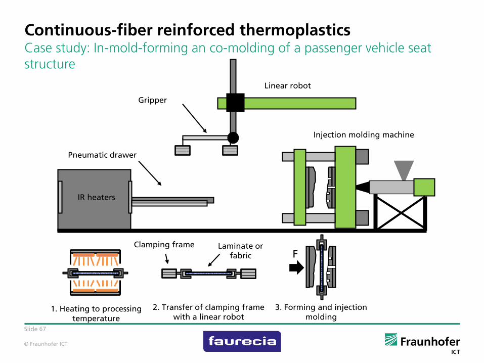
Continuous-fiber reinforced thermoplastics Case study: In-mold-forming an co-molding of a passenger vehicle seat structure
IR heaters
Pneumatic drawer
Laminate orfabric
Linear robot
Gripper
1. Heating to processing temperature
2. Transfer of clamping frame with a linear robot
3. Forming and injection molding
FClamping frame
Injection molding machine
© Fraunhofer ICT
Slide 68
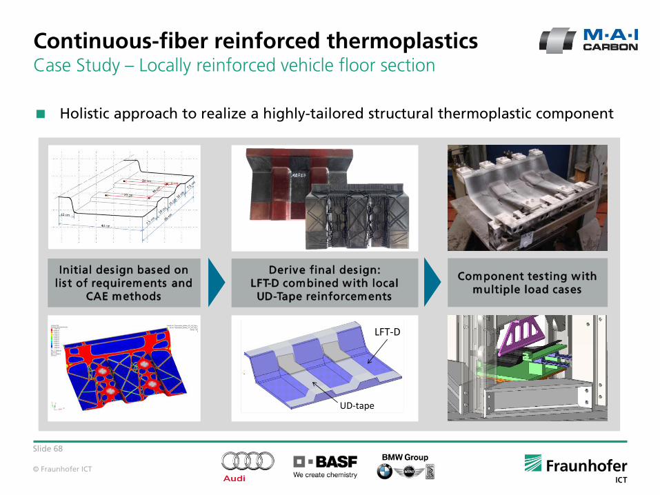
Continuous-fiber reinforced thermoplasticsCase Study – Locally reinforced vehicle floor section
Holistic approach to realize a highly-tailored structural thermoplastic component
Derive final des ign:LFT-D combined with local
UD-Tape reinforcements
Initial design based on lis t of requirements and
CAE methods
Component testing with multiple load cases
UD-tape
LFT-D
© Fraunhofer ICT
Slide 69
Economical Benefits of Tailored Thermoplastic Composites
Strength and Stiffness can reach close to the level of Epoxy based CFRP components
Complete flexibility in tailoring the part. Fiber orientation in any angle.
Local reinforcements possible Local use of UD tapes for structural optimization
High degree of functional integration does minimize the costs
Integration of inserts, rips, bossing etc. possible
Short cycle times of < 30s possible very high productivity
approx. 1 million parts a year in single part mode
Near net shape tape placement does minimize the waste – Large saving compared to textile based processes
Easy process with low level of down grade
Any waste can be directly recycled by feeding it back to LFT-D

© Fraunhofer ICT
Slide 70
Overview of process technologies
*1Continuous-fiber preform
RTM
© Fraunhofer ICT
Slide 71
Contact details
Prof. Dr.-Ing. Frank Henning
Deputy Director Fraunhofer Institute for Chemical Technology ICT
Director Department Polymer Engineering
Joseph-von-Fraunhofer Strasse 776327 Pfinztal, Germany
Phone: +49 721 4640 420Mail: [email protected]: http://www.ict.fraunhofer.de
Director Institute of Vehicle System Technology -Lightweight technology
Rintheimer Querallee 2, Building 70.0476131 Karlsruhe, Germany
Phone: +49 721 608 45905Mail: [email protected]: http://www.fast.kit.edu\lbt
Dr.-Ing. Timo Huber
Deputy Director Department Polymer Engineering
Joseph-von-Fraunhofer Strasse 776327 Pfinztal, Germany
Phone: +49 721 4640 473Mail: [email protected]: http://www.ict.fraunhofer.de