technological issues and industrial application of matrix ... · by choosing to view this document,...
TRANSCRIPT

© 2013 IEEE
IEEE Transactions on Industrial Electronics, Vol. 60, No. 10, pp. 4260-4271, October 2013
Technological Issues and Industrial Application of Matrix Converters: A Review
L. Empringham,J. W. Kolar,J. Rodriguez,P. W. Wheeler,J. C. Clare
This material is published in order to provide access to research results of the Power Electronic Systems Laboratory / D-ITET / ETH Zurich. Internal or personal use of this material is permitted. However, permission to reprint/republish this material for advertising or promotional purposes or for creating new collective works for resale or redistribution must be obtained from the copyright holder. By choosing to view this document, you agree to all provisions of the copyright laws protecting it.
4260 IEEE TRANSACTIONS ON INDUSTRIAL ELECTRONICS, VOL. 60, NO. 10, OCTOBER 2013
Technological Issues and Industrial Applicationof Matrix Converters: A Review
Lee Empringham, Member, IEEE, Johann W. Kolar, Fellow, IEEE, Jose Rodriguez, Fellow, IEEE,Pat W. Wheeler, Member, IEEE, and Jon C. Clare, Senior Member, IEEE
Abstract—This paper presents a review of the current state ofthe art in terms of practical matrix converter technologies. Presentsolutions to the numerous technological issues and challengesfaced when implementing viable matrix converters are discussed.The reported use of the matrix converters in different applicationsis also presented together with a review of current industrialapplications.
Index Terms—Matrix converters.
I. INTRODUCTION
THE MATRIX converter is an ac–ac power convertertopology based mainly on semiconductor switches with
minimal requirements for passive components. It consists of amatrix of bidirectional switches arranged such that any inputphase can be connected to any output phase. As in the majorityof cases, a three-input three-output converter will consist of a“matrix” of nine bidirectional switches, hence the term “matrixconverter.” The gating of the devices is modulated to achievethe desired output voltage.
The matrix converter first appeared in the literature in a bookby Gyugi and Pelly [1] in 1976 and in a journal publication byDaniels and Slattery [2] in 1978 (submitted for publication in1976), and these both presented the direct ac–ac power circuitconcept. In these publications, it was also described as a “forcecommutated cycloconverter.” Since then, as with many powerconverter topologies, work has concentrated on the derivationof modulation and control strategies. In comparison to a dc-linkvoltage source inverter (VSI), the modulation of the switchesin the matrix converter is more difficult since three changingvoltages can be used for the modulation. Methods analogous toVSI modulation strategies which use only the most positive andnegative available voltages are presented in [3].
Manuscript received January 25, 2011; revised April 23, 2011 and July 15,2011; accepted August 17, 2011. Date of publication September 4, 2012; dateof current version May 16, 2013.
L. Empringham, P. W. Wheeler, and J. C. Clare are with the Power Elec-tronics, Machines and Control Group, Faculty of Engineering, The Universityof Nottingham, Nottingham NG7 2RD, U.K. (e-mail: [email protected]; [email protected]; [email protected]).
J. W. Kolar is with the Power Electronic Systems Laboratory, 8092 Zurich,Switzerland (e-mail: [email protected]).
J. Rodriguez, is with the Department of Electronics Engineering, Uni-versidad Tecnica Federico Santa Maria, Valparaíso 2390123, Chile (e-mail:[email protected]).
Color versions of one or more of the figures in this paper are available onlineat http://ieeexplore.ieee.org.
Digital Object Identifier 10.1109/TIE.2012.2216231
The control and modulation of a matrix converter is a verysignificant research subject area, and detailed analysis is beyondthe scope of this paper. It is, however, in many ways verysimilar to that of a traditional VSI. The difference being thatthe switching states of the converter do not need to be chosenbased only on the desired output voltage but can also include theinput current. Many modulation algorithms have been presentedin the literature.
In [4], both the input current and the output voltage aretaken into account, and all three available input voltages areused in the modulation of the converter. The space vectormodulation (SVM) technique described in [5] and [6] hasalso been successfully applied to matrix converters. In [7],the SVM technique under abnormal input conditions is exam-ined. Advanced methods such as the predictive control tech-nique described in [8] and the sliding mode control describedin [9] have also been analyzed and implemented. A generalizedtechnique for the modulation of matrix converters is describedin [10], and a modulation technique for matrix converters withany number of output phases is presented in [11].
Once the modulation algorithm functions correctly and theconverter output voltage follows the demanded voltage, theimplementation of current and speed control loops is exactlythe same process as would be followed for a VSI inverter.
As well as the lack of bulky dc-link components, these con-trol methods help to define some of the well-known attributesof this converter topology such as the voltage transfer ratio of86%, sinusoidal input and output current, and controllable inputpower factor. Since there are no energy storage components,any power pulsations present at the output of the converterwill also be present at the input of the converter. This impliesthat the matrix converter will not be the ideal solution forpulsed loads when the input power quality is important for theapplication. It is highly suited, however, to constant power loadssuch as sinusoidal motor drives such as induction machines orpermanent-magnet synchronous machines (PMSMs).
Fig. 1 shows a schematic diagram of a three-input three-output matrix converter. A detailed review of the characteristicsof the matrix converter is described in [12]. Since this typeof converter is completely reversible and bidirectional, theinput and output can be arbitrarily defined according to theapplication. In this example, the voltage-stiff supply is definedas the input, and the current-stiff motor is defined as theoutput, but this can be reversed depending on the application.While, at first glance, the matrix converter seems to be a morecomplicated concept when compared to a VSI, it has beenshown in [13] that the VSI can be thought of as a subset of the
0278-0046/$31.00 © 2012 IEEE

EMPRINGHAM et al.: TECHNOLOGICAL ISSUES AND INDUSTRIAL APPLICATION OF MATRIX CONVERTERS 4261
Fig. 1. Schematic representation of a three-input-phase three-output-phasedirect matrix converter.
matrix converter, and techniques to modulate and control onecan be used on the other.
This paper will present a review of present industrial appli-cations of the matrix converter and will address the solutionsto the technological issues and barriers surrounding the design,construction, and implementation of such converters.
II. BIDIRECTIONAL SWITCH TECHNOLOGY
The main building block of the matrix converter is thebidirectional semiconductor switch. A single device that canboth conduct current in each direction and block voltage in bothdirections is currently not commercially available, althoughsome work has been reported into the monolithic bidirectionalswitch in [14]–[16], and various bidirectional insulated gatebipolar transistor (IGBT) structures were presented in [17]. Thefollowing section will describe common arrangements used togenerate the necessary bidirectional switches.
A. Switch Technologies
In the infancy of the research into matrix converters, the bipo-lar junction transistor was the most commonly used controlledswitch [18]. Other options include the MOSFET, the gateturnoff thyristor (GTO), and the integrated gate commutatedthyristor (IGCT). The use of the MOSFET is typically restrictedto low-power applications due to the limited blocking voltagesavailable, and the limited switching frequency of both the GTOand the IGCT limits their use in matrix converter applications.
Other power semiconductor devices include the MOS turnoffthyristor (MTO) described in [19] and the MOS controlledthyristor (MCT) described in [20]. The MTO, like the GTO, wasdesigned for high-power applications, and similar limitationson switching frequency exist; nevertheless, matrix convertersusing MTOs have been reported [21] together with the lowerpower MCTs [22].
Most matrix converter applications currently use IGBT de-vices and diodes to create the power circuit. The reverse block-
Fig. 2. Possible bidirectional switch arrangements. (a) DB arrangement.(b) CE arrangement. (c) CC arrangement. (d) RB-IGBT arrangement.
ing IGBT (RB-IGBT) [23]–[25] is also gaining popularity sinceantiparallel diodes can be eliminated from the converter.
B. Active Device Arrangements
Bidirectional switches must be constructed from availableunidirectional devices. Fig. 2 shows some typical arrangements.The diode bridge (DB) arrangement uses only one active de-vice, but the conduction losses are higher than other arrange-ments since the current flows through one switch and twodiodes. The common emitter (CE) and common collector (CC)arrangements allow the current direction to be controlled, andthis allows greater flexibility when performing the commutationof current between input phases. Arrangement (d) is for devicesthat can block voltage in both directions such as the RB-IGBTor MTO.
The simple DB arrangement requires only one gate drive perbidirectional switch but suffers the highest conduction losses ofall the arrangements. The fact that there is only one control-lable device per switch also means that advanced commutationtechniques which remove the need for snubbers cannot be usedsuch as those described in [3] and [26]. It does, however, offersimpler control and less gate drive requirements than the otheroptions. Matrix converter prototypes have been built using thisarrangement [18].
The RB-IGBT arrangement together with the CC configu-ration only requires six isolated gate drive power supplies incontrast to the nine required by the CE arrangement. Sincethe CE arrangement is modular in structure and requires onlyone power supply per bidirectional switch, it may be better forhigh-power converters where the physical size of the converterbecomes significant and the stray inductance of bus bars mayprevent the use of the six isolated power supply methods.
C. Matrix Converter Reliability
The reliability of matrix converters is often intuitivelythought of as being less than that of more traditional industrialdrive topologies such as the rectifier–VSI or the back-to-backpulse width modulated (PWM) rectifier–inverter topologiesbecause of the increase in the number of semiconductors used.Textbook reliability studies have shown, however, in [27] and[28] that this is not necessarily the case. If a matrix converterusing a typical bidirectional switch arrangement such as theone shown in Fig. 2(b) and (c) is assumed, 18 IGBTs and 18diodes are needed together with associated gate driver circuitry,compared to the six IGBTs and 12 diodes of the rectifier–VSI

4262 IEEE TRANSACTIONS ON INDUSTRIAL ELECTRONICS, VOL. 60, NO. 10, OCTOBER 2013
drive and the 12 diodes and IGBTs of the back-to-back VSIconverter. The failure rate for the matrix converter is increaseddue to the increased number of devices, but the voltage stressto which the matrix converter devices are submitted is muchreduced compared to the VSI topologies. The IGBT blockingvoltage would typically be around 590 V for the rectifier–VSIand 750 V for the back-to-back VSI for a 400-V line–linesystem, whereas devices in a matrix converter would only besubjected to a half-wave sinusoidal voltage with peak-inputline-to-line magnitude. In [29] and [30], the intrinsic reliabilityof matrix converters due to thermal cycling of the power deviceswhen comparing conventional matrix converters, indirect ma-trix converters, and VSIs has been studied. The conclusion as towhich is the most reliable topology is mainly dependent on theapplication for which the converter will be used. As with manyother converter topologies, the matrix converter reliability canbe improved using robust failure detection algorithms, modifiedcircuit arrangements, and postfailure modulation strategies.In [31], a fast technique to detect and localize a faulty powerdevice using a correlation of the protective clamp circuit currentand the output phase currents is presented. The converter thenuses a fourth leg of the converter to continue the operation ofthe motor. In [32], a multistage fault diagnosis strategy basedon the output current magnitudes and the input voltage sectoris presented together with a modulation strategy to avoid theuse of the failed device. Fault-tolerant four-leg detection andmodulation schemes are presented in [33]. These strategies canbe employed to continue satisfactory operation after a failurehas occurred.
III. POWER MODULE IMPLEMENTATION
Implementing the power circuit for a matrix converter is notas straightforward as it would typically be for a VSI. This isdue to a lack of available power modules arranged in a suitableconfiguration. Modules to create VSI converters have beenavailable for many years. Prototype matrix converters, however,have often been constructed using discrete IGBTs and diodeswhich makes the demonstration of any potential space savingsdifficult. Some bespoke power modules, built for particularprojects or research demonstrators, are reported in the literature.Some of these modules are now commercially available.
A. Early Experimental Matrix Converter Power Modules
If more semiconductors could be integrated into a singlemodule, an improvement in the case to semiconductor ratiowould result, and hence, a higher power density would bepossible. Several projects have been carried out in recent yearsthat take advantage of the higher levels of integration thatVSI structures have enjoyed for many years, in order to fullydemonstrate the size advantage of the matrix converter.
One of the first reported matrix converter power modules isdescribed in [34]. Here, a 100-A 1200-V module contains threeCC-arranged bidirectional switches, connected to form oneoutput leg of a three-input three-output direct matrix converter.This module was designed and manufactured by EUPEC.
Fig. 3. Schematic diagram of the power module containing three CC-arrangedbidirectional switches.
Fig. 4. Schematic diagram of the power module containing two CC-arrangedbidirectional switches and one CE bidirectional switch.
Fig. 3 shows a schematic representation of the developed powermodule.
In [35], techniques to create a low-cost matrix converterpower module are discussed. An interesting arrangement of CEand CC bidirectional switches described in [36] is suggestedtogether with a method of reducing the number of isolated gatedrive circuits to three. Fig. 4 shows the internal arrangement ofthe proposed power modules. It consists of one CE-arrangedbidirectional switch and two CC bidirectional switches. Themidpoints of the bidirectional switches can be used togetherwith six external diodes to form a clamp circuit. A traditionalclamp circuit requires 12 diodes, but the arrangement of CCand CE switches in the power module allows some of the powerdiodes within the module to form part of the clamp circuit.
The same authors, in a later paper and in collaboration withDanfoss Drives, report an experimental traditional CC-arranged25-A 1200-V three-phase-to-single-phase module used to inte-grate the converter into an industrial induction motor [37].
One of the most widely used matrix converter modules wasdeveloped by EUPEC/Infineon and was reported in [38]. Astandard Econo3 sized module was used to implement a CC-arranged full three-phase-to-three-phase matrix converter ratedat 30 A and 1200 V. Many experimental and demonstrationprojects used this module as the basis for the matrix converter[39]–[41]. It offers a very high level of integration and powerdensity, although with a power module of this rating, theauxiliary circuitry, such as gate drives, power supplies, andcontrollers, becomes a large part of any converter volume. Afull schematic diagram of the EUPEC matrix converter moduleis shown in Fig. 5.
In [42], enough devices to create a third of a matrix con-verter were integrated into a single module by InternationalRectifier Corporation Italy. The EMP-M50P12 was rated at

EMPRINGHAM et al.: TECHNOLOGICAL ISSUES AND INDUSTRIAL APPLICATION OF MATRIX CONVERTERS 4263
Fig. 5. Schematic diagram of the EUPEC power module containing nineCC-arranged bidirectional switches, arranged to form a complete three-inputthree-output matrix converter.
Fig. 6. Schematic diagram of the EMP-M50P12 power module containingone third of the devices needed for a complete 3 by 3 matrix converter.
50 A and 1200 V. The internal arrangement is different fromthe typical single output phase arrangement in that it containsthree IGBTs connected to one input phase and three IGBTsconnected to an output phase. This was done so that the externalPCB arrangement could be simplified, and in this way, eachpower module requires only two isolated power supplies. It isreported that both the collector and emitter connections wereavailable, and this enabled overcurrent protection based on Vceto be implemented. These connections are not available on allmodules. A schematic diagram of the internal layout of thepower module is shown in Fig. 6.
A project to integrate a matrix converter onto an electrome-chanical actuator (EMA) for aerospace applications was re-ported in [43]. The power module contained all of the IGBTsand reverse diodes to create a single output leg of a direct matrixconverter rated at 600 V and 300 A. The module, manufacturedby Semelab for the Electrically Driven Advanced ActuatorSystem (EDAAS) project, also contained antiparallel low-lossSchottky diodes in the output connection to enable the robustdetection of the output current direction in order to perform thecurrent commutation. A schematic of the internal configurationof the module is shown in Fig. 7. It was also constructed usingan AlSiC baseplate for improved reliability. A photograph ofthe module can be seen in Fig. 8. This module later became theSemelab SML300MAT06; see Table I.
A 100-A 1200-V power module using RB-IGBTs wasdemonstrated in [24]. The module was jointly developed byPowerex Corporation, USA, and Mitsubishi Electric PowerSemiconductor Device Works, Japan, and contains all of thedevices necessary to create a three-phase-to-three-phase con-
Fig. 7. Schematic diagram of the internal layout of the three CE-arrangedbidirectional switches to form one output leg of a matrix converter includingthe antiparallel output diodes.
Fig. 8. Semelab 300-A 600-V 3× bidirectional switch module developed forthe EDAAS project.
TABLE IPRESENTLY AVAILABLE COMMERCIAL POWER MODULES
ARRANGED TO CONSTRUCT MATRIX CONVERTERS
Fig. 9. Schematic diagram of the internal layout of the RB-IGBT-arrangedbidirectional switches to form a three-input three-output matrix converterincluding the antiparallel output diodes.
verter. Similar modules have also been described in [44]. Aschematic diagram showing the internal connection of the RB-IGBTs to form the power module is shown in Fig. 9.
4264 IEEE TRANSACTIONS ON INDUSTRIAL ELECTRONICS, VOL. 60, NO. 10, OCTOBER 2013
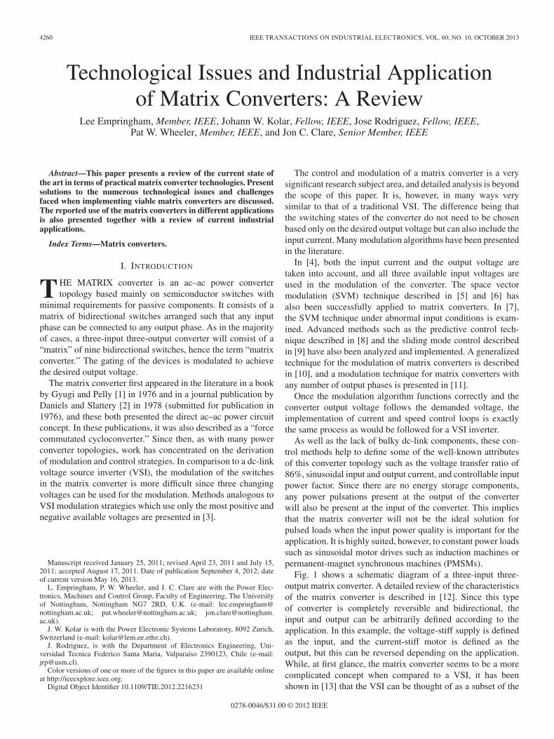
Fig. 10. Schematic diagram of the internal circuit of the DIM600EZM17-E000. It contains three CE-arranged 1700-V 600-A bidirectional switches toform one output leg of a matrix converter.
Fig. 11. Dynex E-type 600-A 1700-V 3× bidirectional switch module.
In [45], a 100-kW matrix converter prototype is described.The three-phase-to-three-phase converter is constructed usingthree power modules, each containing three bidirectionalswitches rated at 1700 V and 600 A. The power module wasbuilt by Dynex Semiconductor using a standard E-type packagewith a modification in the internal bus structure to implementthe CE-arranged bidirectional switches. This module has alsobeen implemented using 500-A silicon carbide antiparalleldiodes. A schematic diagram of the internal circuit arrangementof the Dynex DIM600EZM17-E000 described earlier is shownin Fig. 10. Fig. 11 shows a photograph of the module.
The developments described earlier have concentrated solelyon the power module arrangement and implementation. Re-search into incorporating intelligent-power-module function-ality such as gate drive and control into the power moduleswas carried out in [34] and [46]. Related to the concept ofintegration of control electronics, the work carried out in [47]was aimed at the analysis of the electromagnetic fields presentin a resonant bidirectional switch module and the creation ofa low field area within the switch. This magnetic null area wasintended to be used for sensitive low voltage control electronics.
B. Commercially Available Matrix Converter Power Modules
Recent interest in matrix converter technology and some ofthe previously mentioned prototype/demonstrator projects hasresulted in a few manufacturers offering commercial powermodules for matrix converter applications. These range fromindividual bidirectional switches to three-phase-to-single-phase
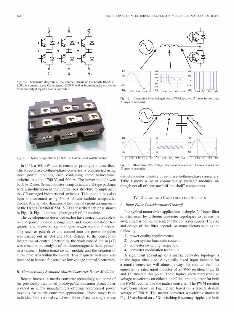
Fig. 12. Illustrative filter voltages for a PWM rectifier (Y -axes in volts andX-axes in seconds).
Fig. 13. Illustrative filter voltages for a matrix converter (Y -axes in volts andX-axes in seconds).
output modules to entire three-phase-to-three-phase converters.Table I shows a list of commercially available modules, al-though not all of them are “off-the-shelf” components.
IV. DESIGN AND CONSTRUCTIVE ASPECTS
A. Input Filter Considerations/Tradeoff
In a typical motor drive application, a simple LC input filteris often used by different converter topologies to reduce theswitching harmonics presented to the converter supply. The sizeand design of this filter depends on many factors such as thefollowing:
1) power quality requirements;2) power system harmonic content;3) converter switching frequency;4) converter modulation technique.A significant advantage of a matrix converter topology is
in the input filter size. A typically sized input inductor fora matrix converter will almost always be smaller than theequivalently rated input inductor of a PWM rectifier. Figs. 12and 13 illustrate this point. These figures show representativevoltage waveforms on either side of the input inductor for boththe PWM rectifier and the matrix converter. The PWM rectifierwaveforms shown in Fig. 12 are based on a typical dc-linkvoltage of 750 V. The matrix converter waveforms shown inFig. 13 are based on a 5% switching frequency ripple, and both

EMPRINGHAM et al.: TECHNOLOGICAL ISSUES AND INDUSTRIAL APPLICATION OF MATRIX CONVERTERS 4265
Fig. 14. Typical input filter configurations. Single stage and two stage.
systems use an input supply of 240 V Line to Neutral and a1-kHz PWM frequency. It can be clearly seen that the ripplevoltage across the inductors are very different, and if the sameinput current ripple is required in both cases, a much largervalue of inductance will be required for the PWM rectifier. Thisleads to a more costly and bulky input inductor for the PWMrectifier.
The choice of input filter arrangement and size dependsmostly on the application requirements, but some guidelineshave been presented in the literature. The basic strategy is toprovide a filter that provides a voltage-stiff port to the matrixcircuit and attenuates the switching frequency componentsenough to satisfy the power quality requirements while avoid-ing any resonance of the input filter. The input filter resonancecan be excited by either supply-side harmonics or harmonicsgenerated by the matrix converter modulation itself. Typicalsingle- and two-stage input filter arrangements are shownin Fig. 14.
Detailed analysis of the harmonic performance of differentmodulation techniques is presented in [49], and the harmoniceffects of different arrangements of the switching patterns forSVM are shown in [50]. In general, supply-side harmonicsare of a much lower frequency than the switching frequencyharmonics which can help to decouple the two when designingthe input filter; this, however, is not always true and is con-siderably more challenging in frequency wild power systemssuch as those found on modern aircraft or in variable-speedgenerator applications. Further analysis of the input filter designcompared to rectifier–VSI topologies can be found in [51].Further work on input filter design and limitations was alsodescribed in [52].
There are also decisions to be made in the actual physicalimplementation of the filter once the theoretical values ofinductance, capacitance, and resistance have been finalized.The input capacitors can be arranged in either a Delta or Stararrangement. The advantage in the Delta arrangement is thatcapacitances of 1/3 of that of the Star arrangement can be usedwhereas higher voltages must be sustained. The input inductorcan be realized as a three-phase reactor or three individual in-ductances. The three-phase reactor offers a smaller solution butlittle common mode attenuation. Although this is not necessary,it may be important if an electro-magnetic interference (EMI)filter is to be integrated.
B. Power Circuit Layout
As with all converter topologies which include switchingdevices, a voltage-stiff port needs to be connected via theswitches to a current-stiff port. In this discussion, the input willbe thought of as the voltage-stiff (capacitive) port and the output
will be thought of as the inductive current-stiff port, as shownin Fig. 1. This is analogous to the VSI in that a dc-link capacitorprovides the input to the inverter stage and the inductive load;typically, an induction motor is connected to the output.
Since the typical input filter of the matrix converter consistsof an LC arrangement, the capacitance generally forms thevoltage-stiff input of the power circuit. It is important thatthe parasitic inductance between the input capacitors and thepower stage is minimized to avoid overvoltages across thebidirectional switches during current commutation. It is for thisreason that the input filter needs to be properly integrated intothe power circuit using similar power planes as used in VSIs.The input filter cannot realistically be separated from the powercircuit unless local capacitance is provided to assist currentcommutation.
Analysis of the current paths at the input of the matrixconverter and associated inductances of different planar bus-bararrangements is discussed in [53].
C. Protection
Since there are no freewheeling paths within the matrixconverter circuit for the inductive load current, the protectionof the main power devices due to overvoltages needs to beaddressed. Overvoltages can occur due to an open circuit of theload. This may be caused by commutation failure, device/gatedrive failure, or, simply, a turnoff of the drive.
Schemes have been suggested, which use the matrix con-verter to create freewheel paths so that the inductive load energycan be transferred back to the supply, such as those describedin [54] and [55]. These techniques have the advantage that noextra protection devices are necessary, but the method cannotfunction correctly if a failure occurs in the gate drive or devicescurrently used to create the freewheel paths. This method alsowill not work if the input supply is cut off, i.e., there would benowhere to transfer the load energy to.
The classical method of protecting the matrix converter is touse a DB arrangement on the input and output of the converteras described in [56]. This arrangement provides a path for theinductive load current during turnoff. The size of the capacitoris typically small and can be calculated based on the loadinductance, initial clamp voltage, and final clamp voltage
WLoad =1
2L(i2a + i2b + i2c
)=
3
4LI2. (1)
The maximum load energy is calculated in (1), where WLoad
is the energy stored in the inductance of the motor, L is theequivalent line inductance of the motor, and ia, ib, and ic are theline currents of the motor. The change in energy of the clampcapacitor from its initial voltage to its final voltage can be usedto calculate the size of the capacitor and is shown in
WLoad =1
2CClamp
(V 2MAX − V 2
INI
)(2)
where CClamp is the capacitance of the clamp capacitor, VMAX
is the maximum allowable clamp voltage, and VINI is the initialclamp voltage.
The size of the clamp capacitor can be minimized with theuse of an active dissipation device [41], [57]. This arrangement

4266 IEEE TRANSACTIONS ON INDUSTRIAL ELECTRONICS, VOL. 60, NO. 10, OCTOBER 2013
Fig. 15. High-speed DB clamp circuit with chopper.
Fig. 16. Collector voltage feedback to prevent device overvoltage.
can be seen in Fig. 15. An active clamp of this type can alsoimprove the reliability and robustness of the matrix converterpower circuit. In the event of failures which repeatedly generatean open circuit of the load, the energy transferred to the clampcircuit can be dissipated, and the converter may continue tooperate, albeit with a potentially poorer power quality.
Similar clamp arrangements can be used for the indirector sparse matrix converter topologies [58]. These perform thesame function described previously but using fewer diodesbecause of the circuit topology.
A passive protection scheme was suggested in [59] to achievea low-cost protection solution. Here, varistors are connectedacross the load terminals at the output of the converter togetherwith a similar arrangement at the input to the converter. Cal-culations and measurements of the energy dissipation requiredfor different drive configurations are presented to enable thesizing of the dissipation devices. Another technique, offeredin addition to this, in the same publication used a Zener diodeconnected to the collector of the driven IGBT in order to drivethe IGBT into its active region in the event of an overvoltagein order to dissipate the excess load energy. This arrangementcan be seen in Fig. 16. The clamping voltage is set by the Zenerdiode and has the advantage that active control circuitry is notnecessary. It was shown that, under certain circumstances, onlythe IGBT dissipation method was necessary to protect the drive.IGBT lifetime predictions using this mode of operation couldnot be performed.
V. MATRIX CONVERTER APPLICATIONS/PROTOTYPES
The low voltage transfer ratio is often seen as the biggestdisadvantage of a matrix converter if a like-for-like replacementfor an industrial drive is required. Some attempts to addressthe problem on an overmodulation basis have been performed[60], but inevitably, input power quality is sacrificed in favorof output drive capability. Work based on minor topologychanges, particularly using the indirect matrix converter, hasbeen proposed in [61] at the cost of increased complexityand size.
In applications where the load motor in the drive systemcan be specified and appropriately selected, the voltage transferratio limitation is not an issue.
In motor drive where the converter is integrated with or soldwith the motor, clearly, the matrix converter should have asize and a weight advantage over competing VSI technologies.Work on a 4-kW integrated matrix converter-induction machinedrive was described in [37]. The design and construction of a30-kW version was further described in [49].
The potential size and weight advantages of the matrix con-verter and the elevated temperature capability due to the lackof dc-link components lend themselves to aircraft applications.Several prototype aircraft actuator projects have been reportedin the literature. In [62], collaboration with Smiths Aerospaceled to the creation of a 7-kW matrix converter used to drivea 10 000-r/min PMSM integrated into an electrohydrostaticactuator. The matrix converter was chosen in this applicationbecause of the ability to be driven from a frequency wild supply.This prototype was based on the Infineon Economac matrixconverter module.
A higher power direct drive EMA was described in [43].Collaboration with Smiths Aerospace, which later became GEAviation, resulted in the development of both a 20-kW inte-grated matrix converter and a 20-kW 10 000-r/min PMSM tocreate a fully integrated rudder actuator.
An indirect matrix converter drive was developed in col-laboration with MOOG for an EMA application describedin [63]. The same requirements for a variable frequency supplywith aircraft power quality specifications were desired as perthe previous two examples. The main difference in this projectwas the requirement to prevent the regeneration of energyback to the supply. This process can be more easily achievedusing an indirect matrix converter using a suitable dissipationcircuit connected to the standard protective clamp circuit. Acomprehensive comparison of the conventional matrix con-verter, the indirect matrix converter, and the back-to-back PWMrectifier–inverter is described in [64].
A deep sea remotely operated vehicle (ROV) matrix con-verter drive application was the subject in [65]. The extremepressure experienced by ROVs and the lack of large and fragiledc-link components were the reason that the matrix converterwas chosen as a potential topology for the application. Researchinto the effects of high atmospheric pressure on the constituentparts of typical drive systems was carried out at 300 bar. Thepaper also investigates the use of observer-based sensorlesscontrol of a PMSM using the matrix converter.
The matrix converter has also been applied to drive the rotorcircuit of a doubly fed induction generator for wind turbineapplications using direct [66] and indirect matrix converters[67]. This technique has the advantage that a relatively lowpower four-quadrant power converter can be used to controla high-power generator system. Research into the stability ofsuch systems is presented in [68], and the effects of rotor-sideharmonics in a similar system were presented in [69].
In [70], a reduced matrix converter (three phase to two phase)was used to control a wind turbine generator and drive a single-phase transformer which was then connected through an acrectifier to a dc transmission line. The efficiency under different

EMPRINGHAM et al.: TECHNOLOGICAL ISSUES AND INDUSTRIAL APPLICATION OF MATRIX CONVERTERS 4267
modulation and control techniques was addressed in [71] forthis type of matrix converter. Further work into a novel matrixconverter topology to allow the coupling of energy generationresources and the grid was recently presented in [72].
Further industrial interest is outlined in [60]. This paper high-lights the characteristics of the matrix converter from a man-ufacturer’s perspective in terms of cost, competitiveness, andsize. The overmodulation performance of the matrix converteris also evaluated for applications where a direct replacement ofan industrial VSI drive is required.
Matrix converters are finding application in the power supplygeneration area. Instead of the typical motor drive application,an output filter is used in order to provide a voltage source ofthe desired amplitude and frequency. This concept allows fixedvoltage and frequency power supplies to be implemented anddriven from variable frequency diesel generators. In [73], theissues regarding the control of the output voltage and frequencywhen using a resonant LC output filter under stringent powerquality requirements are described. The operation of the gen-erator at the optimum speed, particularly under lightly loadedconditions, can offer increased fuel efficiency. The applicationof the matrix converter in polyphase generator systems has beendiscussed in [74] and [75]. In this case, the matrix convertertransforms not only the input frequency and voltage but also thenumber of phases. Since the matrix converter circuit is modular,any number of input and output phases can be implemented.Protection strategies for the matrix converter when used as agrid supply converter are discussed in [76].
A similar microturbine generation system was describedin [77]. The main challenge here was the high input frequencyof 2221 Hz. A new switching technique is proposed in orderto minimize the number of switching events while maintainingharmonic performance.
An interesting use of a matrix converter using only unidi-rectional switches was described in [78]. Here, a matrix ofnine unidirectional switches was used to drive an inductionmachine. A dc offset was demanded for each of the outputphases to enable a sinusoidal component to be present at theoutput of the converter. Two methods to then remove the effectof the converter output dc component were suggested in orderto maintain the performance of the induction machine. Fig. 17shows the arrangement of the unidirectional matrix converter,input filter, and specially wound induction machine.
The main advantage of this technique was that the numberof IGBTs and diodes is reduced to 50% of those requiredby a conventional three-phase to three-phase matrix converterand that, since the current can only flow in one direction, thecurrent commutation process becomes inherently safe. Anotherapplication of a unidirectional matrix converter was to drivea five-phase fault-tolerant brushless dc (BLDC) motor for thepump in an electrohydrostatic actuator [79]. A unidirectionalmatrix converter was also used to drive a switched reluctancemotor (SRM) in [80]. The power circuit consists of six outputphases. Each winding on the SRM is galvanically isolatedfrom the others and is driven by two of the output phases ofthe converter. In one of these output phases, the devices arearranged such that current can only flow in one direction fromthe supply to the motor, and in the other phase, current can
Fig. 17. Diagram of the unidirectional matrix converter feeding an inductionmachine.
Fig. 18. Diagram of power circuit arrangement for the five-phase unidirec-tional matrix converter feeding a PMSM.
flow from the motor winding to the supply. The switching ofthe converter is then modulated to deliver the desired outputvoltage and therefore control the current in the motor. Themain disadvantage of the aforementioned unidirectional matrixconverter topologies is that the input current quality is verypoor. The “pulsed power” nature of the SRM and the BLDCfurther increase the disturbance seen on the input currents ofthe converters. This is due to the fact that there are no energystorage components within the matrix converter circuit andany power disturbances at the output will inevitably result ina disturbance at the input. Figs. 18 and 19 show diagrams ofthe circuit arrangement for the unidirectional matrix convertersdriving the five-phase BLDC motor and the three-phase SRM.
VI. PRODUCTS IN THE MARKET
To date, the only drive manufacturers to offer matrix con-verter products are Yaskawa and Fuji Electric Systems. Bothseries are aimed at the general drives market with emphasison the energy saving potential with the inherent regenerationcapability.

4268 IEEE TRANSACTIONS ON INDUSTRIAL ELECTRONICS, VOL. 60, NO. 10, OCTOBER 2013
Fig. 19. Diagram of power circuit arrangement for the six-phase unidirec-tional matrix converter feeding a three-phase SRM.
Fuji Electric Systems has developed the FRENIC-MC seriesof matrix converters which are available in 15- and 30-kWversions with a 230-V input and 15-, 30-, and 45-kW versionsusing a 480-V input [81].
Yaskawa currently advertises two ranges of converters for useon low voltage power systems of either 230- or 480-V input.The AC7 converter is available in four power levels rangingfrom 7.5 to 60 hp for a 230-V input and in five power levelsranging from 10 to 125 hp for the 480-V option. The AC7offers all of the typical features that one would expect froma programmable industrial vector drive with some additionalbenefits. It is a fully regenerative drive with a 150% overloadcapability in either direction for 1 min and with a maximuminput current total harmonic distortion of 7%. Since it is fullyregenerative, it is advertised as an energy-reducing technologyfor applications such as lifts, hoists, conveyors, and escalators.All external add-on units such as external breaking resistors areeliminated in the AC7.
Yaskawa also offers a range of medium-voltage matrix con-verter drives. The FSDrive-MX1S is aimed at two voltagesystems, 3 and 6 kV. A major selling point is again the potentialefficiency savings in using an inherently regenerative drive. Thepower level of the different models in the MX1S series rangefrom 200 kW to 3 MW for a 3-kV system and from 400 kWto 6 MW for the 6-kV version. The power factor is alwaysmaintained to be greater than 0.95 with an efficiency of 98%.
These products can be seen as the start of a growing range ofindustrial products from other companies. As more companiesinvest in matrix converter technology, it will encourage otherdrives manufacturers to follow.
VII. CONCLUSION/FUTURE TRENDS
The matrix converter offers many potential benefits to thepower converter industry. It will not be the best solution forall uses, but it offers significant advantages for many differentapplications. This paper has reviewed the present matrix con-verter work from the perspective of implementing a realisticconverter. While, for many years, it seemed that the matrixconverter would be restricted to a small range of niche areas, the
commitment to invest in matrix converters from several largeindustrial drives manufacturers may see the start of an industry-wide uptake of this technology.
Cutting-edge research in power converters is currently aimedat the use of wide-bandgap materials such as gallium nitride(GaN) and silicon carbide (SiC). These materials offer potentialadvantages over silicon devices, and research into the use ofthese devices in prototype power converters is being reported.Potential advantages include the following:
1) faster switching—lower switching loss;2) higher temperature operation—higher power density;3) higher voltage structures.
Where these advantages may seem ideal and exactly whatpower electronics researchers have been looking for, consid-erable research needs to be carried out in order to realize thesepotentials. The decrease in switching losses due to the promisedincrease in switching speed cannot be presently implementeddue to the associated problems caused to the EMI performanceof the drive. Similarly, present packaging technology is thelimiting factor for the increased temperature operation of thesenew devices. A more integrated approach to power converterdesign will be needed in the future which takes packaging,thermal management, circuit layout, and EMI performance intoaccount at the same time. In this way, optimized structureswhich minimize commutation paths and conducted EMI whileobtaining high-temperature operation will be attained. Someexamples of the use of SiC devices in direct converter topolo-gies can be found in [82] and [83].
REFERENCES
[1] L. Gyugi and B. Pelly, Static Power Frequency Changers: Theory, Perfor-mance and Applications. New York: Wiley, 1976.
[2] A. Daniels and D. Slattery, “New power convertor technique employingpower transistors,” Proc. IEE, vol. 125, no. 2, pp. 146–150, Feb. 1978.
[3] J. Oyama, T. Higuchi, E. Yamada, T. Koga, and T. Lipo, “New controlstrategy for matrix converter,” in Proc. IEEE PESC/IEEE Power Electron.Spec. Conf., Jun. 1989, vol. 1, pp. 360–367.
[4] A. Alesina and M. Venturini, “Analysis and design of optimum-amplitudenine-switch direct ac–ac converters,” IEEE Trans. Power Electron., vol. 4,no. 1, pp. 101–112, Jan. 1989.
[5] L. Huber and D. Borojevic, “Space vector modulation with unity inputpower factor for forced commutated cycloconverters,” in Conf. Rec. IEEEIAS Annu. Meeting, Oct. 1991, vol. 1, pp. 1032–1041.
[6] D. Casadei, G. Serra, A. Tani, and L. Zarri, “Matrix converter modulationstrategies: A new general approach based on space-vector representationof the switch state,” IEEE Trans. Ind. Electron., vol. 49, no. 2, pp. 370–381, Apr. 2002.
[7] X. Wang, H. Lin, H. She, and B. Feng, “A research on space vectormodulation strategy for matrix converter under abnormal input-voltageconditions,” IEEE Trans. Ind. Electron., vol. 59, no. 1, pp. 93–104,Jan. 2012.
[8] J. Rodriguez, J. Espinoza, M. Rivera, F. Villarroel, and C. Rojas, “Predic-tive control of source and load currents in a direct matrix converter,” inProc. IEEE ICIT , 2010, pp. 1826–1831.
[9] M. Hamouda, F. Fnaiech, K. Al-Haddad, and H. Kanaan, “Matrixconverter control: A sliding mode approach,” in Proc. IEEE IECON,Nov. 2004, vol. 3, pp. 2295–2300.
[10] H. Hojabri, H. Mokhtari, and L. Chang, “A generalized technique ofmodeling, analysis, and control of a matrix converter using SVD,” IEEETrans. Ind. Electron., vol. 58, no. 3, pp. 949–959, Mar. 2011.
[11] S. Ahmed, A. Iqbal, and H. Abu-Rub, “Generalized duty-ratio-basedpulsewidth modulation technique for a three-to-phase matrix converter,”IEEE Trans. Ind. Electron., vol. 58, no. 9, pp. 3925–3937, Sep. 2011.
[12] P. Wheeler, J. Rodriguez, J. Clare, L. Empringham, and A. Weinstein,“Matrix converters: A technology review,” IEEE Trans. Ind. Electron.,vol. 49, no. 2, pp. 276–288, Apr. 2002.

EMPRINGHAM et al.: TECHNOLOGICAL ISSUES AND INDUSTRIAL APPLICATION OF MATRIX CONVERTERS 4269
[13] D. G. Holmes and T. A Lipo, “Implementation of a controlled rectifierusing ac–ac matrix converter theory,” IEEE Trans. Power Electron., vol. 7,no. 1, pp. 240–250, Jan. 1992.
[14] R. Sittig and F. Heinke, “Monolithic bidirectional switch, part I: Deviceconcept,” Solid State Electron., vol. 44, no. 8, pp. 1387–I392, Aug. 2000.
[15] F. Heinke and R. Sittig, “Monolithic bidirectional switch, part II: Sim-ulation of device characteristics,” Solid State Electron., vol. 44, no. 8,pp. 1393–1398, Aug. 2000.
[16] F. Heinke and R. Sittig, “The monolithic bidirectional switch (MBS) in amatrix converter application,” in Proc. ISPSD, 2001, pp. 367–371.
[17] N. Luther-King, M. Sweet, O. Spulber, K. Vershinin, M. De Souza, andE. Narayanan, “MOS control device concepts for ac–ac matrix converterapplications: The HCD concept for high-efficiency anode-gated devices,”IEEE Trans. Electron Devices, vol. 52, no. 9, pp. 2075–2080, Sep. 2005.
[18] C. Neft and C. Schauder, “Theory and design of a 30-hp matrix converter,”in Conf Rec. IEEE IAS Annu. Meeting, Oct. 1988, vol. 1, pp. 934–939.
[19] A. Huang, Y. Li, K. Motto, and B. Zhang, “MTO thyristor: An efficient re-placement for the standard GTO,” in Conf Rec. IEEE IAS Annu. Meeting,1999, vol. 1, pp. 364–372.
[20] H. Mehra, “Applications of MOS controlled (MCT) and MOS turn-off(MTO) thyristors,” in Proc. IEEE Power Eng. Soc. Summer Meet., 2000,vol. 2, pp. 1219–1222.
[21] T. Podlesak, J. Tuttle, P. Wheeler, and L. Empringham, “Matrix converterusing MOS turn-off thyristors,” in Conf. Rec. 24th Int. Power ModulatorSymp., 2000, pp. 107–110.
[22] K. Kerris, P. Wheeler, J. Clare, and L. Empringham, “Implementation ofa matrix converter using p-channel MOS-controlled thyristors,” in Proc.8th Int. Conf. (IEE Conf. Publ. No. 475) Power Electron. Variable SpeedDrives, 2000, pp. 35–39.
[23] S. Bernet, T. Matsuo, and T. Lipo, “A matrix converter using reverseblocking NPT-IGBTs and optimized pulse patterns,” in Proc. IEEEPESC/IEEE Power Electron. Spec. Conf., Jun. 1996, vol. 1, pp. 107–113.
[24] E. Motto, J. Donlon, M. Tabata, H. Takahashi, Y. Yu, and G. Majumdar,“Application characteristics of an experimental RB-IGBT (reverse block-ing IGBT) module,” in Conf. Rec. IEEE IAS Annu. Meeting, 2004, vol. 3,pp. 1540–1544.
[25] C. Klumpner and F. Blaabjerg, “Using reverse-blocking IGBTs in powerconverters for adjustable-speed drives,” IEEE Trans. Ind. Appl., vol. 42,no. 3, pp. 807–816, May/Jun. 2006.
[26] N. Burany, “Safe control of four-quadrant switches,” in Conf. Rec. IEEEIAS Annu. Meeting, Oct. 1989, vol. 1, pp. 1190–1194.
[27] P. Wheeler, J. Clare, L. de Lillo, K. Bradley, M. Aten, C. Whitley, andG. Towers, “A comparison of the reliability of a matrix converter and acontrolled rectifier-inverter,” in Proc. Eur. Conf. Power Electron. Appl.,2005, p. 7.
[28] P. Wheeler, J. Clare, L. de Lillo, K. Bradley, M. Aten, C. Whitley, andG. Towers, “A reliability comparison of a matrix converter and an18-pulse rectifier for aerospace applications,” in Proc. EPE-PEMC,Sep. 1, 2006, pp. 496–500.
[29] L. Wei, R. Lukaszewski, and T. Lipo, “Analysis of power-cycling capa-bility of IGBT modules in a conventional matrix converter,” IEEE Trans.Ind. Appl., vol. 45, no. 4, pp. 1443–1451, Jul./Aug. 2009.
[30] L. Wei, T. Lipo, and R. Lukaszewski, “Comparison of IGBT cycling ca-pabilities for different ac/ac topologies,” IEEE Trans. Ind. Appl., vol. 46,no. 6, pp. 2475–2483, Nov./Dec. 2010.
[31] S. Khwan-on, L. de Lillo, L. Empringham, and P. Wheeler, “Fault-tolerantmatrix converter motor drives with fault detection of open switch faults,”IEEE Trans. Ind. Electron., vol. 59, no. 1, pp. 257–268, Jan. 2012.
[32] K. Nguyen-Duy, T.-H. Liu, D.-F. Chen, and J. Hung, “Improvement ofmatrix converter drive reliability by online fault detection and a fault-tolerant switching strategy,” IEEE Trans. Ind. Electron., vol. 59, no. 1,pp. 244–256, Jan. 2012.
[33] S. Kwak, “Four-leg-based fault-tolerant matrix converter schemes basedon switching function and space vector methods,” IEEE Trans. Ind.Electron., vol. 59, no. 1, pp. 235–243, Jan. 2012.
[34] J. Chang, T. Sun, A. Wang, and D. Braun, “Compact ac–ac converter using3-in-1 IBPMs and adaptive commutation,” in Proc. IEEE Int. Conf. PEDS,1999, vol. 1, pp. 438–443.
[35] C. Klumpner, P. Nielsen, I. Boldea, and F. Blaabjerg, “New steps towardsa low-cost power electronic building block for matrix converters,” in Conf.Rec. IEEE Ind. Appl. Conf., 2000, vol. 3, pp. 1964–1971.
[36] P. Nielsen, F. Blaabjerg, and J. Pedersen, “Novel solutions for protectionof matrix converter to three phase induction machine,” in Conf. Rec. IEEEIAS Annu. Meeting, Oct. 1997, vol. 2, pp. 1447–1454.
[37] C. Klumpner, P. Nielsen, I. Boldea, and F. Blaabjerg, “A new matrixconverter motor (MCM) for industry applications,” IEEE Trans. Ind.Electron., vol. 49, no. 2, pp. 325–335, Apr. 2002.
[38] M. Hornkamp, M. Loddenkoetter, M. Muenzer, O. Simon, andM. Bruckmann, “EconoMAC the first all-in-one IGBT module for matrixconverters,” in Proc. PCIM, 2001, pp. 1–6.
[39] O. Simon, J. Mahlein, M. Muenzer, and M. Bruckmarm, “Modern so-lutions for industrial matrix-converter applications,” IEEE Trans. Ind.Electron., vol. 49, no. 2, pp. 401–406, Apr. 2002.
[40] P. Wheeler, J. Clare, M. Apap, L. Empringham, C. Whitley, andG. Towers, “Power supply loss ride-through and device voltage dropcompensation in a matrix converter permanent magnet motor drive for anaircraft actuator,” in Proc. IEEE PESC/IEEE Power Electron. Spec. Conf.,2004, vol. 1, pp. 149–154.
[41] J. Andreu, J. De Diego, I. de Alegria, I. Kortabarria, J. Martin, andS. Ceballos, “New protection circuit for high-speed switching and start-upof a practical matrix converter,” IEEE Trans. Ind. Electron., vol. 55, no. 8,pp. 3100–3114, Aug. 2008.
[42] D. Casadei, G. Serra, A. Trentin, L. Zarri, and M. Calvini, “Experimentalanalysis of a matrix converter prototype based on new IGBT modules,” inProc. IEEE ISIE, 2005, vol. 2, pp. 559–564.
[43] L. de Lillo, L. Empringham, P. Wheeler, J. Clare, and K. Bradley,“A 20 kW matrix converter drive system for an electro-mechanicalaircraft (EMA) actuator,” in Proc. Eur. Conf. Power Electron. Appl.,2005, p. 6.
[44] D. Zhou, K. Sun, L. Huang, and K. Sasagawa, “A novel commutationmethod of matrix converter fed induction motor drive using RB-IGBT,”in Conf. Rec. IEEE IAS Annu. Meeting, 2005, vol. 4, pp. 2347–2354.
[45] L. Empringham, P. Wheeler, and J. Clare, “Power density improvementand robust commutation for a 100 kW Si-SiC matrix converter,” in Proc.EPE, 2009, pp. 1–8.
[46] J. Galvez, X. Jorda, M. Vellvehi, J. Millan, M. Jose-Prieto, and J. Martin,“Intelligent bidirectional power switch module for matrix converter ap-plications,” in Proc. Eur. Conf. Power Electron. Appl., 2007, pp. 1–9.
[47] H. Fortin Blanchette and K. Al Haddad, “An efficient approach to de-sign discrete packaging of bidirectional resonant power switch for matrixconverter applications,” IEEE Trans. Power Electron., vol. 23, no. 4,pp. 2195–2200, Jul. 2008.
[48] D. Chamund, B. Findlay, P. W. Wheeler, M. Apap, L. Empringham,M. Bland, and J. C. Clare, “Bi-directional IGBT switches for matrixconverter applications,” in Proc. PCIM, 2004, pp. 676–681.
[49] M. Apap, “Direct Converter Technology Applied to an Integrated Mo-tor Drive,” Ph.D. dissertation, School of Elect. and Electron. Eng.,Nottingham, U.K., 2005.
[50] D. Casadei, G. Serra, A. Tani, and L. Zarri, “Effects of the switchingstrategy on the input power quality of matrix converters,” in Proc. IEEEPower Tech Conf., 2003, vol. 1, p. 8.
[51] S. Bernet, S. Ponnaluri, and R. Teichmann, “Design and loss comparisonof matrix converters, and voltage-source converters for modern ac drives,”IEEE Trans. Ind. Electron., vol. 49, no. 2, pp. 304–314, Apr. 2002.
[52] P. Wheeler and D. Grant, “Optimized input filter design and low-lossswitching techniques for a practical matrix converter,” Proc. IEE Elect.Power Appl., vol. 144, no. 1, pp. 53–60, Jan. 1997.
[53] I. Galkin and A. Suzdalenko, “Analysis of the actual current paths of anintegrated matrix converter,” in Proc. ICEMS, 2009, pp. 1–5.
[54] B. Kwon, B. Min, and J. Kim, “Novel commutation technique of ac–acconverters,” Proc. IEE Elect. Power Appl., vol. 145, no. 4, pp. 295–300,Jul. 1998.
[55] A. Schuster, “A matrix converter without reactive clamp elements foran induction motor drive system,” in Proc. IEEE PESC/IEEE PowerElectron. Spec. Conf., May 1998, vol. 1, pp. 714–720.
[56] P. Nielsen, F. Blaabjerg, and J. Pedersen, “New protection issues of a ma-trix converter: Design considerations for adjustable-speed drives,” IEEETrans. Ind. Appl., vol. 35, no. 5, pp. 1150–1161, Sep./Oct. 1999.
[57] L. Empringham, L. de Lillo, P. Wheeler, and J. Clare, “Matrix converterprotection for more electric aircraft applications,” in Proc. IEEE IECON,2006, pp. 2564–2568.
[58] J. Schonberger, T. Friedli, S. Round, and J. Kolar, “An ultra sparse matrixconverter with a novel active clamp circuit,” in Proc. PCC-Nagoya, 2007,pp. 784–791.
[59] J. Mahlein, M. Bruckmann, and M. Braun, “Passive protection strategy fora drive system with a matrix converter and an induction machine,” IEEETrans. Ind. Electron., vol. 49, no. 2, pp. 297–303, Apr. 2002.
[60] D. Zhou, K. Phillips, G. Skibinski, J. McCarty, M. Loth, B. Buchholz,D. Braun, and R. Lukaszweski, “Evaluation of ac–ac matrix converter,a manufacturer’s perspective,” in Conf. Rec. IEEE IAS Annu. Meeting,2002, vol. 3, pp. 1558–1563.
[61] T. Wijekoon, C. Klumpner, P. Zanchetta, and P. Wheeler, “Implementationof a hybrid ac–ac direct power converter with unity voltage transfer,”IEEE Trans. Power Electron., vol. 23, no. 4, pp. 1918–1926, Jul. 2008.

4270 IEEE TRANSACTIONS ON INDUSTRIAL ELECTRONICS, VOL. 60, NO. 10, OCTOBER 2013
[62] P. Wheeler, J. Clare, M. Apap, L. Empringham, L. De Lilo,K. Bradley, C. Whitley, and G. Towers, “An electro-hydrostaticaircraft actuator using a matrix converter permanent magnet motordrive,” in Proc. 2nd Int. Conf. (Conf. Publ. No. 498) PEMD, 2004, vol. 2,pp. 464–468.
[63] A. Trentin, P. Zanchetta, P. Wheeler, and J. Clare, “Performance assess-ment of matrix converter and two stage matrix converter for EMA inaircraft application,” in Proc. IEEE PESC/IEEE Power Electron. Spec.Conf., 2008, pp. 2692–2697.
[64] T. Friedli and J. Kolar, “Comprehensive comparison of three-phaseac–ac matrix converter and voltage dc-link back-to-back convertersystems,” in Proc. IPEC, 2010, pp. 2789–2798.
[65] P. Snary, B. Bhangu, C. Bingham, D. Stone, and N. Schofield, “Matrixconverters for sensorless control of PMSMs and other auxiliaries on deep-sea ROVs,” Proc. IEE Elect. Power Appl., vol. 152, no. 2, pp. 382–392,Mar. 2005.
[66] L. Zhang, C. Watthanasarn, and W. Shepherd, “Application of a matrixconverter for the power control of a variable-speed wind-turbine drivinga doubly-fed induction generator,” in Proc. IECON, Nov. 1997, vol. 2,pp. 906–911.
[67] R. Pena, R. Cardenas, E. Reyes, J. Clare, and P. Wheeler, “Controlof a doubly fed induction generator via an indirect matrix converterwith changing dc voltage,” IEEE Trans. Ind. Electron., vol. 58, no. 10,pp. 4664–4674, Oct. 2011.
[68] R. Cardenas, R. Pena, G. Tobar, J. Clare, P. Wheeler, and G. Asher, “Sta-bility analysis of a wind energy conversion system based on a doubly fedinduction generator fed by a matrix converter,” IEEE Trans. Ind. Electron.,vol. 56, no. 10, pp. 4194–4206, Oct. 2009.
[69] K. Spiteri, C. Staines, and M. Apap, “Power control of doubly fed induc-tion machine using a rotor side matrix converter,” in Proc. ISIE, 2010,pp. 1445–1450.
[70] A. Garces and M. Molinas, “Reduced matrix converter operated as cur-rent source for off-shore wind farms,” in Proc. EPE/PEMC, 2010,pp. T12-149–T12-154.
[71] A. Garces and M. Molinas, “A study of efficiency in a reduced matrixconverter for offshore wind farms,” IEEE Trans. Ind. Electron., vol. 59,no. 1, pp. 184–193, Jan. 2012.
[72] X. Liu, P. Wang, P. Loh, and F. Blaabjerg, “A three-phase dual-inputmatrix converter for grid integration of two ac type energy resources,”IEEE Trans. Ind. Electron., vol. 60, no. 1, pp. 20–30, Jan. 2013.
[73] P. Zanchetta, P. Wheeler, J. Clare, M. Bland, L. Empringham, andD. Katsis, “Control design of a three-phase matrix-converter-based ac–acmobile utility power supply,” IEEE Trans. Ind. Electron., vol. 55, no. 1,pp. 209–217, Jan. 2008.
[74] S. Turri, A. Lacaze, and J. Kauffmann, “De-synchronized generator usinga synchronous turbo-generator and a matrix converter,” in Proc. IEEEIEMDC, 2003, vol. 1, pp. 60–66.
[75] A. Beguin, A. Rufer, and A. Lacaze, “Poly-phased matrix converter forlarge synchronous generators—Design of the voltage surge protection,”in Proc. EPE, 2009, pp. 1–10.
[76] B. Augdahl, H. Hess, and B. Johnson, “Output protection strategies formatrix converters in distributed generation applications,” in Conf. Rec.IEEE IAS Annu. Meeting, 2006, vol. 4, pp. 2082–2089.
[77] H. Nikkhajoei and M. Iravani, “A matrix converter based micro-turbinedistributed generation system,” IEEE Trans. Power Del., vol. 20, no. 3,pp. 2182–2192, Jul. 2005.
[78] M. Ziegler, D. Domes, W. Hofmann, and S. El-Barbari, “A newrectifier based topology for electrical drives: S-A-X-converter,” inProc. IEEE PESC/IEEE Power Electron. Spec. Conf., 2004, vol. 4,pp. 2924–2928.
[79] C. Gerada, K. Bradley, X. Huang, A. Goodman, C. Whitley, andG. Towers, “A 5-phase fault-tolerant brushless permanent magnet motordrive for an aircraft thin wing surface actuator,” in Proc. IEEE IEMDC,May 2007, vol. 2, pp. 1643–1648.
[80] A. Goodman, K. Bradley, and P. Wheeler, “Evaluation of the single sidedmatrix converter driven switched reluctance motor,” in Conf. Rec. IEEEIAS Annu. Meeting, 2004, vol. 3, pp. 1847–1851.
[81] I. Sato, A. Odaka, Y. Tamai, and H. Mine, “Technologies for practicalmotor drive system with matrix converter,” Fuji Electric Advanced Tech-nology, Ltd, Tokyo, Japan, 2007.
[82] F. Schafmeister, S. Herold, and J. Kolar, “Evaluation of 1200 V-Si-IGBTs and 1300 V-SiC-JFETs for application in three-phase very sparsematrix ac–ac converter systems,” in Proc. IEEE APEC, 2003, vol. 1,pp. 241–255.
[83] M. Heldwein and J. Kolar, “A novel SiC J-FET gate drive circuit forsparse matrix converter applications,” in Proc. IEEE APEC, 2004, vol. 1,pp. 116–121.
Lee Empringham (M’10) received the B.Eng.(Hons.) degree in electrical and electronic engineer-ing and the Ph.D. degree from The University ofNottingham, Nottingham, U.K., in 1996, and 2000,respectively.
He then joined the Power Electronics, Machinesand Control Group within the School of Electricaland Electronic Engineering, The University ofNottingham to work on matrix converter commuta-tion techniques. Since then, he has been employedby the group as a research fellow to support different
ongoing matrix converter projects and has recently been appointed to theposition of Principal Research Fellow. His research interests include directac–ac power conversion, variable-speed ac motor drives using different circuittopologies, and more electric/electric aircraft applications.
Dr. Lee Empringham is a member of the Institution of Electrical Engineers.
Johann W. Kolar (M’89–SM’04–F’10) received thePh.D. degree (summa cum laude/promotio sub aus-piciis praesidentis rei publicae) from the Universityof Technology Vienna, Vienna, Austria.
Since 1984, he has been working as an Indepen-dent International Consultant in close collaborationwith the University of Technology Vienna, in thefields of power electronics, industrial electronics, andhigh-performance drives. He has proposed numerousnovel PWM converter topologies and modulationand control concepts, e.g., the VIENNA rectifier and
the three-phase ac–ac sparse matrix converter. He has published more than300 scientific papers in international journals and conference proceedingsand has filed more than 75 patents. He joined the Power Electronic SystemsLaboratory, Swiss Federal Institute of Technology (ETH) Zurich, Zurich,Switzerland, on February 1, 2001. His current research interests include ac–acand ac–dc converter topologies with low effects on the mains, e.g., for powersupply of telecommunication systems, more electric aircraft, and distributedpower systems in connection with fuel cells. Further main areas are therealization of ultracompact intelligent converter modules employing the latestpower semiconductor technology (SiC), novel concepts for cooling and EMIfiltering, multidomain/multiscale modeling and simulation, pulsed power, andbearingless motors.
Dr. Kolar was the recipient of the Best Transactions Paper Award of theIEEE Industrial Electronics Society in 2005. He is a member of the Instituteof Electrical Engineers of Japan (IEEJ) and of technical program committeesof numerous international conferences in the field (e.g., Director of the PowerQuality Branch of the International Conference on Power Conversion andIntelligent Motion). From 1997 to 2000, he was an Associate Editor of theIEEE TRANSACTIONS ON INDUSTRIAL ELECTRONICS, and since 2001,he has been an Associate Editor of the IEEE TRANSACTIONS ON POWER
ELECTRONICS. Since 2002, he has also been an Associate Editor of the Journalof Power Electronics of the Korean Institute of Power Electronics and a memberof the Editorial Advisory Board of the IEEJ Transactions on Electrical andElectronic Engineering.
Jose Rodriguez (M’81–SM’94–F’10) received theEngineer degree in electrical engineering fromthe Universidad Tecnica Federico Santa Maria(UTFSM), Valparaiso, Chile, in 1977, and theDr. Ing. degree in electrical engineering from theUniversity of Erlangen, Erlangen, Germany, in 1985.
He has been with the Department of ElectronicsEngineering, UTFSM, since 1977, where he is cur-rently a Full Professor and Rector. He has coauthoredmore than 300 journal and conference papers. Hismain research interests include multilevel inverters,
new converter topologies, control of power converters, and adjustable-speeddrives.
Prof. Rodríguez is a member of the Chilean Academy of Engineering. Hehas been an Associate Editor of the IEEE TRANSACTIONS ON POWER ELEC-TRONICS and the IEEE TRANSACTIONS ON INDUSTRIAL ELECTRONICS
since 2002. He was the recipient of the Best Paper Award from the IEEETRANSACTIONS ON INDUSTRIAL ELECTRONICS in 2007 and the Best PaperAward from the IEEE INDUSTRIAL ELECTRONICS MAGAZINE in 2008.

EMPRINGHAM et al.: TECHNOLOGICAL ISSUES AND INDUSTRIAL APPLICATION OF MATRIX CONVERTERS 4271
Pat W. Wheeler (M’00) received the B.Eng. (Hons.)and the Ph.D. degrees in electrical engineering forhis work on matrix converters from the Univer-sity of Bristol, Bristol, U.K., in 1990 and 1994,respectively.
In 1993, he moved to The University ofNottingham, Nottingham, U.K., and worked as aResearch Assistant in the Department of Electricaland Electronic Engineering. In 1996, he became aLecturer in the Power Electronics, Machines andControl Group at The University of Nottingham.
Since January 2008, he has been a Full Professor in the same research group.He has published over 200 papers in leading international conferences andjournals. His research interests are in power conversion and more electricaircraft technology.
Jon C. Clare (M’90–SM’04) was born in Bristol,U.K. He received the B.Sc. and Ph.D. degrees inelectrical engineering from the University of Bristol,Bristol.
Since 1990, he has been with The University ofNottingham, Nottingham, U.K., where he is cur-rently a Professor of Power Electronics and theHead of the Power Electronics, Machines and Con-trol Research Group. His research interests are inpower electronic systems and applications, powerelectronic converter topologies, and their control. His
work is currently directed toward applications in aerospace, energy systems,and high-power RF.
Prof. Clare is a member of the Institution of Engineering and Technology(IET) England. He is a member of the Editorial Board of the IET Journal ofPower Electronics and is an Associate Editor for the IEEE TRANSACTIONS
ON POWER ELECTRONICS. He is a former member of the Executive Councilof the European Power Electronics Association and the IEEE Power ElectronicsSociety Administrative Committee.