technical manual hard disk controller preliminary ... · technical manual hard disk controller...
TRANSCRIPT

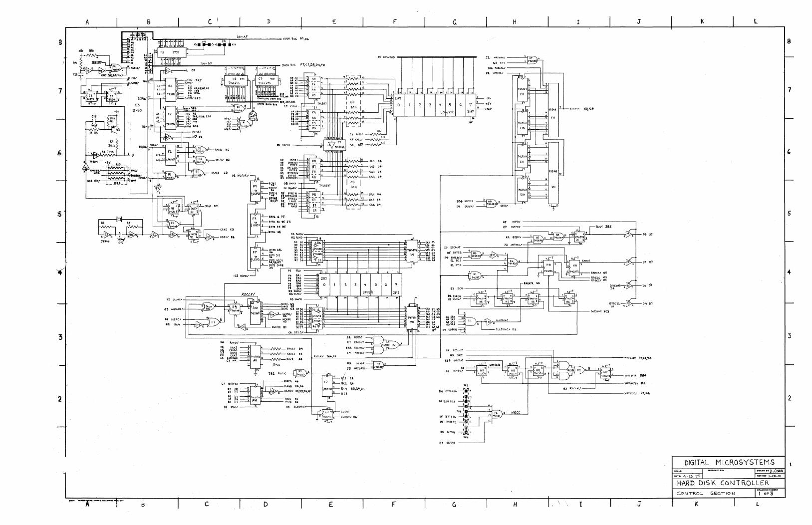
Technical Manual Hard Disk Controller
Preliminary documentation on hard disk controller and multi hard disks. November 23, 19820 Updated, 6/23/83 Finmware 2.7 ORB Updated, 1/06/84 Firmware 3.0 ORB
1.0 HARD DISK CONTROLLER
1.1 OVERVEIW The CPU-floppy disk drive sub-system of a OSC-3/4 hard disk unit may be operated under CP/M in the normal way. However, a second board is necessary for the harddisk. This board is called the Hard Disk Controller (HOC).
The HOC! has its own Z80 CPU with 32K of RAM buffer. It also has a 1K prom. The flow of data for a disk write is as follows:
A. Data exits the host CPU board through J3 (parallel port).
B. Data enters the HOC board through P1h (parallel port) • .
C. Data is converted to serial data by the HOC board.
D. Data exits the HOC board through Pld (drive interface).
E. Serial data is written on the harddisk.
1.2 THEORY OF OPERATION Most of the basic operations of the HOC are stored in ROM as programmed sequences. These include:
page 1
Technical Manual Hard Disk Controller
A. Power up or hard reset ini tialization. B. Host command and data communication. C. Disk read am wr i te operations. D. Error detection.
NOTE--Error correction is handled by fi rmware in RAM.
1.2.1 Power Up or Hard Reset Initialization The HOC begins execution upon power up at OOOOh. If you executed a system reset, the HOC jumps to this location. The initialization procedure begins by setting the stack pointer, clearing the host inter-face status flip-flop. . Next, 1K of the software for operation with your CP 1M or Oasis operating systan is read into memory from track 0, head 0, sector 1 and stored in memory starting at 4100h. The HOC now waits in a loop for a command from the host computer.
When the first commarrl for operating system firmware is received, the firmware does its initilization. This includes finding which volumes are present for a multidrive system, reading an additional 1 or 2 K or firmware from the disk and reading each disks bad sector table.
1.2.2 Host Command and Data Communication The HOC samples the status of the host interface during each loop. If the HOC detects data on the interface, it reads the data and compares it with a "request to send" (51 h). If it is a "request to send," the HOC serrls a "clear to receive" (52h) to the host. The 8 byte command block is read into
page 2
Technical Manual Hard Disk Controller
memory starting at 4080h. The host can sen::l commands to the HOC. '!he commands have been discussed previously.
1.2.3 Disk Read and Write Operations A read commaoo causes a disk read. If an error occurs, the location on the harddisk will be reread the number of times specified by byte 6 of the command block.
The BST is consulted to determine if the disk location is written on a replacement sector on the last two valid tracks. When the correct location is determinoo, the head is selected arrl the difference between the old track and the new track computed.
1.2.4 Error Detection An error message is genera too and the read operation stops if the track number generate3 is greater than the maximum number of tracks on the harddisk. If all is correct, step pulses are generated aoo the head is move3 to the new position on the harddisk. The HrC program wai ts for the SEEK COMPLETE signal from the drive. It waits an additional 20 msec for the head to settle before starting the read.
The next task is to find the correct sector. A sector of data is stored on the harddisk in the following format:
14 l¥tes syrx: 8 l¥tes 1024 l¥tes 4 l¥tes 8 + l¥tes
O's I <Eh I li:Bi:!r I D:rt:a B:I: 0' s
page 3
Technical Manual Hard Disk Controller
The correct sector is foum usirg a read am abort. The first 32 bytes of each sector are read. If the sector read is not the sector previous to the sector wanted, the read is repeated on the next sector. When the sector previous to the desirErl sector is found the HOC reads the entire next sector.
The hardware sequence for a read am abort or a full sector read is identical. The only difference is the HOC software aborts the read after 32 bytes.
1.3.5 HARD. DISK READ The hardware read sequence is started with an output command from the HOC CPU. This resets the byte counter and turns over memory buffer control to the HOC control logic. Data is read off the disk at the beginning of the next sector pulse. The control log ic searches for the sync byte. When the sync byte is read, a bit counter starts and data is shiftErl into a shift register. After 8 bits have been shifted, the data is loaded into the memory buffer. The memory location of the buffer is incremented and more data is stored as each byte is assembled from the disk. This process continues until the HOC CPU takes back control of the memory buffer.
The control logic has several signals which the HOC CPU monitors while data is read off the disk. These signals are:
BYTE32
BUSY
Monitored during a read and abort for the 32 bytes of header data for a sector.
This signal is checked to determine when I
page 4
Technical Manual Hard Disk Controller
ERROR
the disk read is finished.
Error "on", indicates that data read off the disk failErl the Ex::x: check.
BYTE2048 This signal is used to time the hardware portion of the error correction.
When BYTE32 returns to "0", control is returned to the HOC CPU. If the CPU is doi03 a complete sector read, it moniters the BUSY line. When the disk has completErl the read, BUSY returns to "0" am the HOC CPU checks the ERROR line. If ERROR is "0", there is no error in the read am control returns to the HOC CPU. Data is movErl from the HOC data buffer to the host computer RAM am the harddisk read is complete.
1.2.6 Read Error Correction I f ERROR is"''', the HDC CPU does not take over memory control from the HOC control logic. Instead, the CPU monitors BYTE2048 am takes control when it becomes active.
The time between BUSY inactive and BYTE2048 active is the amount of time the error correction hardware needs to generate the required correction information. This information is a bit stream approx-imately 'K bytes long. 'Ibis bit stream is loaded into memory arrl locatErl after the data buffer. The error correction software can correct errors in the data field with this error information. This error correction scheme has the ability to correct a six bit error burst. However, a maximum of 4 bits are corrected because this reduces the probability of a false correction to zero, assuming burst errors of
page 5
Technical Manual Hard Disk Controller
length 11 or less or two errors of length 2 or less.
When the data is corrected, it is transmitted to the host computer am the HOC waits in a loop for another command.
1.2.7 Hard Disk writes A "write command" writes a1K byte block of data to the harddisk. The HOC will retry a write error the number of times specified by bits 0 through 6 of byte 6 of the commam block. The HOC will also perform a read after write to verify data written to the harddisk if bit 7 of byte 6 of the command block is set to "1".
A write sequence begins with a transfer of data from the host CPU to the HOC. This data is stored in the HOC I/O buffer beginning at E017h. Next, the specified disk location is compare1 to entries in the BST. If a match occurs, a specific sector from the spare tracks is used for the write. The correct head is now moved to the track for the wri tee '!his is done in the same manner as a read from the hard disk.
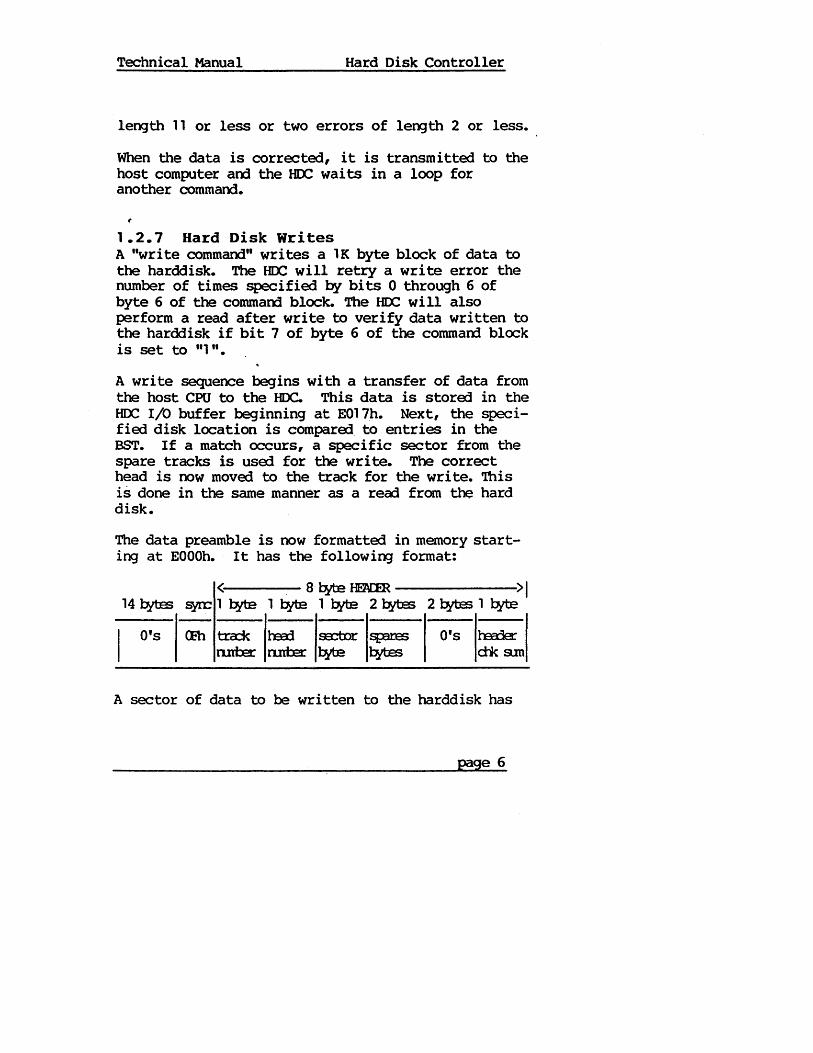
The data preamble is now formatted in memory starting at EOOOh. It has the following format:
< 8·~fEaR >1 1 1¥e 1 l:!tte 1 l:!tte 2 l:!ftes 2~11¥e
O's <Eh t:r:a:X h:xd s:ctor sp:m:s O's h:xrler n.ntB: n.ntB: ~ ~ ctk am
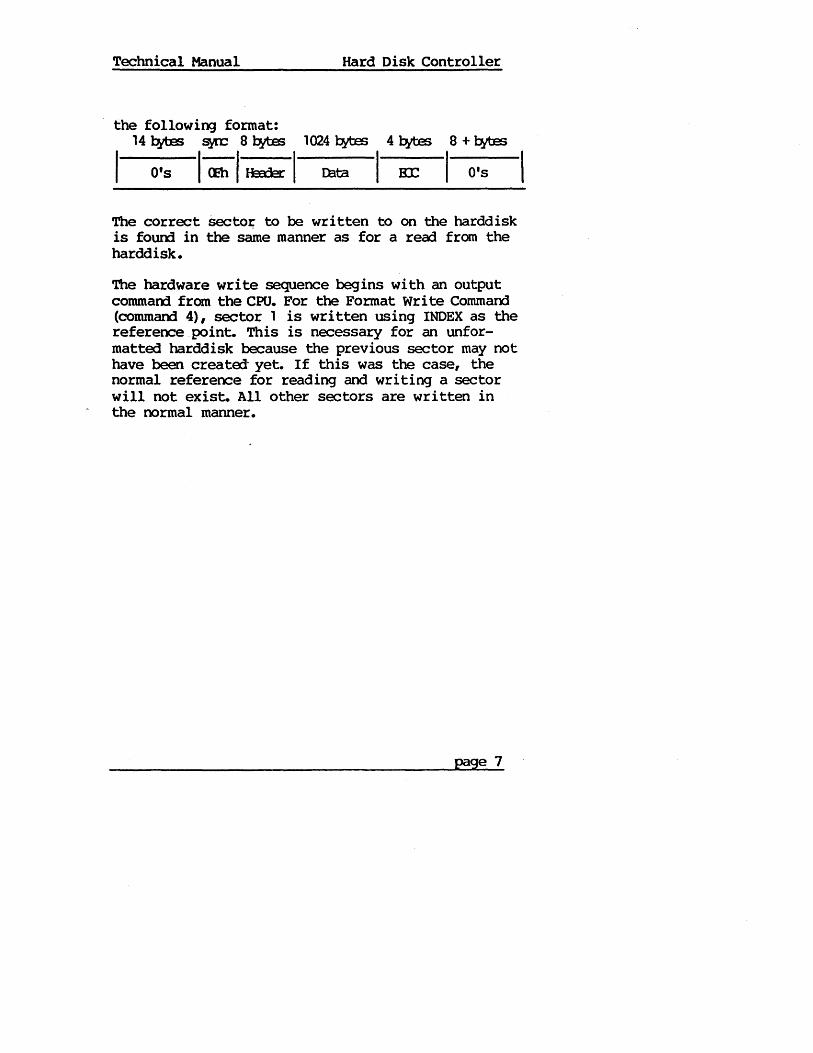
A sector of data to be written to the harddisk has
page 6
Technical Manual
the following format: 14 l!ttes ~ 8 l!ttes
O's l(;bllmk I
Hard Disk Controller
1024 l!ttes 4 l!ttes 8 + l!ttes
D:lta I~ I 0'5
The correct Secto~ to be written to on the harddisk is fourrl in the same manner as for a read from the harddisk.
The hardware write sequence begins with an output commaoo from the CPU. For the Format write Commaoo (command 4), sector 1 is written using INDEX as the reference point. This is necessary for an unformatted harddisk because the previous sector may not have been created- yet. If this was the case, the normal reference for reading and writing a sector will not exist. All other sectors are written in the normal manner.
page 7
Technical Manual Hard Disk Controller
The sector pulse follow ing the CPU output command clocks WRTGATE to "1" and resets the EIX: shift registers (to zero). WR'roATE write enables the harddisk. Control of the data buffer memory is given to the controller logic. The bit counter is already counting in sync with the disk generated clock. All disk write functions are synchronous with this clock. With the bit counter counting, data is read from memory startirg at EOOOh. It is shifted out of the shift register at 7.1 mbits per secom. The En: hardware is generating an ax code while data is being written. After the data preamble am data have been written to the disk, a four byte EIX: code is written. The rest of the sector is filled with O's from the buffer until the next sector pulse. The sector pulse clocks WRTGATE to "0" which disables wr i tes to the harddisk. This completes the hardware write sequence.
1.2.8 Write Error Correction During the time the HOC logic is shifting data to the disk, the HOC CPU is monitoring BUSY and WRTFLT. If a fault condition develops during a disk write, a WRTFLT signal is generated. This results in the HOC CPU regaining control of the RAM, issueing a Fault Reset-write retries are attempted if the command block indicates retries are to be attempted. The HOC will also do a read after write check in the command block requested it.
page 8
Technical Manual Hard Disk Controller
1.3 BOARD DESCRIPTION The HOC has the following subsections:
1. A Z80 CPU operatiOJ at 4Mhz under ROM or RAM control.
2. 16K of CPU executable memory, 16K of I/O buffer memory, am a 1 K prom.
3. Parallel port interface to DOC-3 or DOC-4. 4. HOC board to harddisk drive interface port. 5. HOC control program. 'Ibis program is run by the
Z80 CPU on the HOC board. The program performs 3 major functions:
A. Operate the 16K buffer area. B. Control head select and seek.
Moniter the drive status signals. C. Generate check bits on write and verifiy
on read. Perform error correction if necessary
D. Communicate with the host CP/M
Host CPU to HDC Interface The parallel port interface is the means of communication between the host CPU am the HOC CPU. The two boards are connected by a 26 conductor ribbon cable •.
The host CPU must provide the following I/O signals to operate the interface:
INSTATUS/ An active low signal samples the interface status bits. (gates the status bits onto the host CPU data bus)
INDATA/ When INDATA is active low, data is gated from the interface chip (74LS374 on the HOC board) onto the host CPU's data bus.
(
page 9
Technical Manual Hard Disk Controller
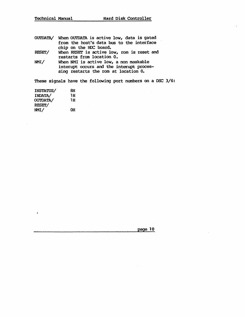
OUTDATA/ When OtrrDATA is active low, data is gated from the host's data bus to the interface chip on the HOC board.
RESET/ When RESET is active low, rom is reset and restarts from location o.
NMI/ When NMI is acti ve low, a non maskable interupt occurs and the int~upt processing restarts the rom at location o.
These signals have the following port numbers on a DSC 3/4:
I NSTATUS/ 8H INDATA/ 1H OtJrDATA/ 1 H RESET/ NMI/ OH
page 10
Technical Manual Hard Disk Controller
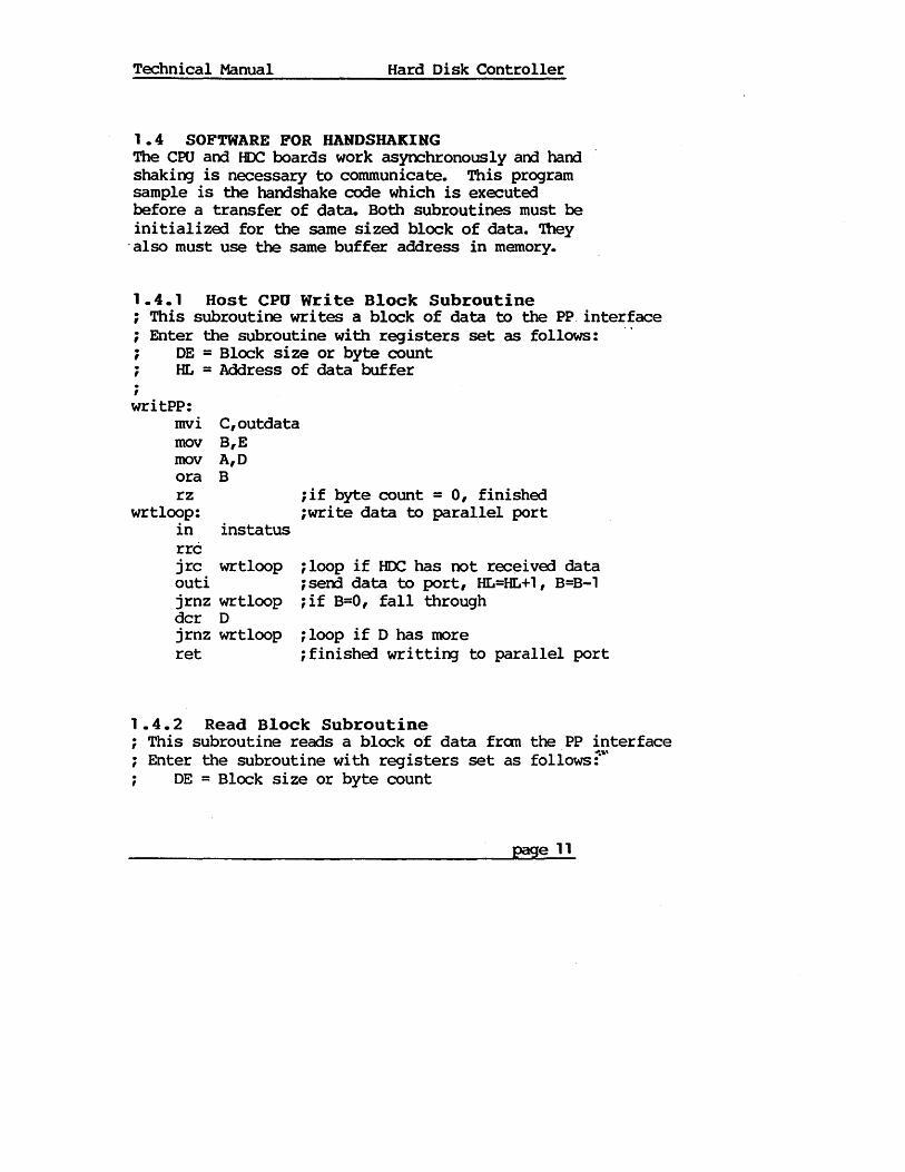
1.4 SOFTWARE FOR HANDSHAKING The CPU and fIDe boards work asynchronously and hand shaking is necessary to communicate. This program sample is the handshake code which is executed before a transfer of data. Both subroutines must be initialized for the same sized block of data. '!hey
. also must use the same buffer address in memory.
1.4.1 Host CPU Write Block Subroutine i This subroutine writes a block of data to the PP interface ; Enter the subroutine with registers set as follows: i DE = Block size or byte count ; HI. = Address of data buffer ; writPP:
mvi C,outdata mov B,E mov A,D ora B rz
wrtloop: in
iif byte count = 0, finished iwrite data to parallel port
instatus rrc j rc wrtloop ; loop if IIDC has not rec~i vErl data outi i serrl data to port, HL=HL+ 1, B=B-l jrnz wrtloop ; if B=O, fall through dcr D j rnz wrtloop ; loop if D has more ret ifinishErl writting to parallel port
1.4.2 Read Block Subroutine ; This subroutine reads a block o'f data fran the PP interface ; Enter the subroutine with registers set as follows t'
DE = Block size or byte count
page 11
Technical Manual Hard Disk Controller
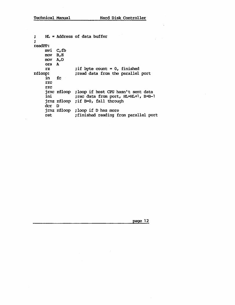
; HL = Address of data buffer ; readPP:
mvi C,fb mov B,E mov A,D ora A rz
rdloop: in fc rrc rrc
; if byte cOunt = 0, finished ;read data fran the parallel port
jrnc rdloop ; loop if host CPU hasn' t sent data ini ;rec data fran port, HL=HL+1, B=B-1 jrnz rdloop ; if B=O, fall through dcr D j rnz rdloop ; loop if D has more ret ;finished reading from parallel port
page 12
Technical Manual Hard Disk Controller
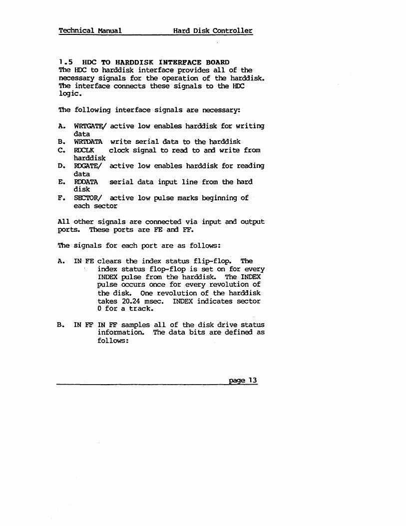
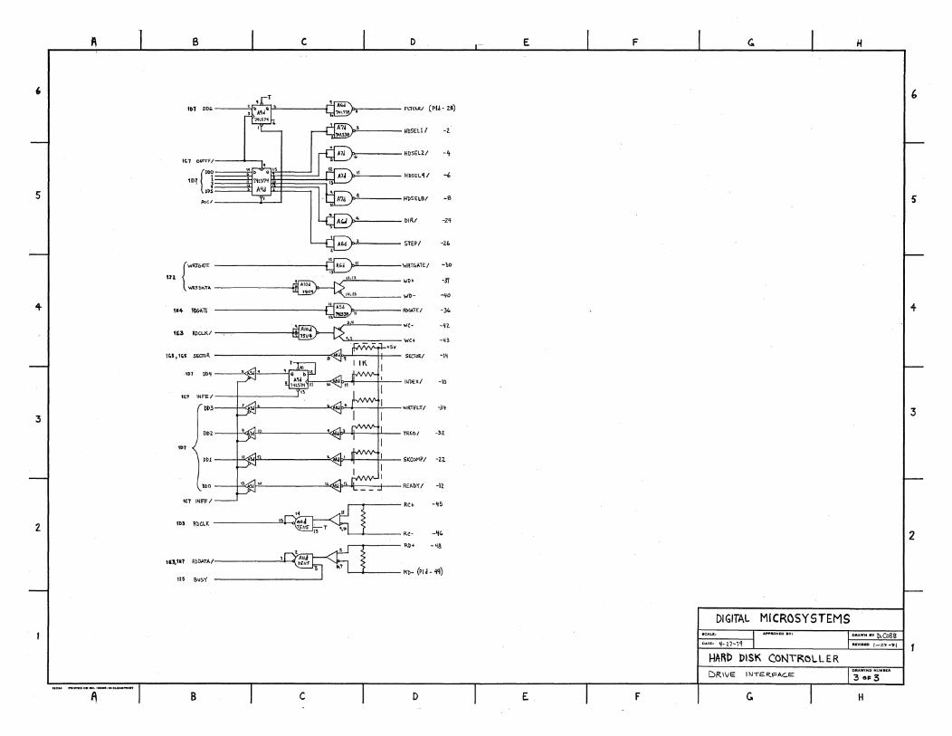
1.5 HDC TO HARDDISK INTERFACE BOARD The HOC to harddisk interface provides all of the necessary signals for the operation of the harddisk. The interface connects these signals to the HOC logic.
The following interface signals are necessary:
A. WRTGATE/ active low enables harddisk for writing data
B. WRTDATA write serial data to the harddisk C. ROCLK clock signal to recrl to aoo write from
harddisk D. RDGATE/ active low enables harddisk for reading
data E. RDDATA serial data input line from the hard
disk F. SEX:TOR/ active low pulse marks beginning of
each sector
All other signals are connected via input and output ports. These ports are FE am FF.
The signals for each port are as follows:
A. IN FE clears the index status flip-flop. The index status flop-flop is set on for every INDEX pulse from the harddisk. The INDEX pulse occurs once for every revolution of the disk. One revolution of the harddisk takes 20.24 msec. INDEX indicates sector o for a track.
B. IN FF IN FF samples all of the disk drive status information. The data bits are defined as follows:
page 13
Technical Manual Hard Disk Controller
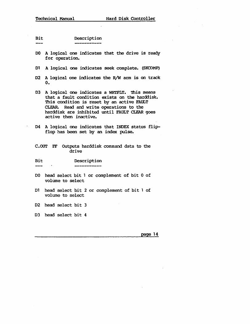
Bit Description
DO A logical one irrlicates that the drive is ready for operation.
01 A logical one indicates seek complete. (S~MP)
02 A logical one irrlicates the R/W arm is on track O.
03 A logical one indicates a WRTFLT. 'Ibis means that a fault corrlition exists on the harddisk. 'Ibis condition is reset by an. active FAULT CLFAR. Read am write operations to the harddisk are inhibited until FAULT CLEAR goes active then inactive.
04 A logical one indicates that INDEX status flipflop has been set by an index pulse.
C.OUT FF Outputs harddisk command data to the drive
Bit Description
DO head select bit 1 or complement of bit 0 of volUme to select
D1 head select bit 2 or complement of bi t 1 of volume to select
D2 head select bit 3
D3 head select bit 4
page 14
Technical Manual Hard Disk Controller
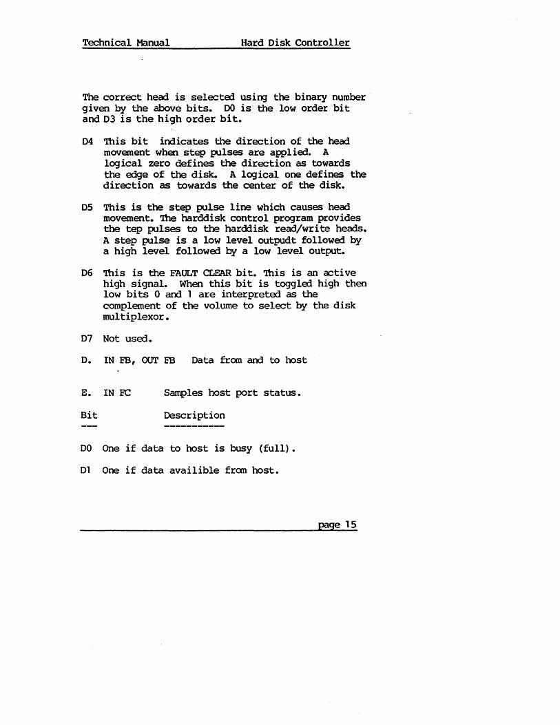
The correct head is selecte1 usiOJ the binary number . given by the above bits. DO is the low order bit and 03 is the high order bit.
04 This bit indicates the direction of the head movement when step pulses are appl ied. A logical zero defines the direction as towards the edge of the disk. A logical one defines the direction as towards the center of the disk.
05 This is the step pulse line which causes head movement. The harddisk control program provides the tep pulses to the harddisk read/write heads. A step pulse is a low level outpudt followe1 by a high level followed by a low level output.
06 This is the FAULT CLEAR bi t. 'Ibis is an active high signal. When this bit is toggle1 high then low bits 0 and 1 are interpreted as the complement of the volume to select by the disk multiplexor.
07 Not used.
o. IN FB, oor FB Data from and to host
E. IN EC Samples host port status.
Bit Description
DO One if data to host is busy (full).
01 One if data availible from host.
page 15

Technical Manual Hard Disk Controller
F. OUT R: Comnaoo to hard disk, bits as follows:
DO One for read request.
01 One for write request.
02 One to give ram to disk interface.
04 One for write enable
06 Sets bit 14 in ram address when disk has ram.
07 Sets bit 15 in ram address when disk has ram.
G. IN FD Samples status of controller hardware, bits as follows:
Bit Description
04 Set if byte 32 has been read.
05 Set if busy with write.
06 Set if bit 2048 processed thru crc circuitry.
07 Set if CRe error occurred.
page 16
Technical Manual Hard Disk Controller
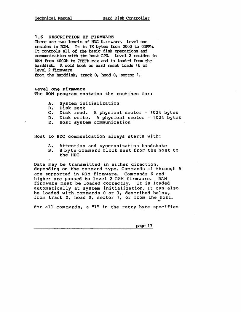
1.6 DESCRIPTION OF FIRMWARE There are two levels of HOC firmware. Level one resides in ROM. It is 1K bytes from 0000 to 03FFh. It controls all of the basic disk operations and communication with the host CPU. Level 2 resides in RAM from 4000h to 7FFFh max and is loaded from the harddisk. A cold boot or hard reset loads 1k of level 2 firmware from the harddisk, track 0, head 0, sector 1.
Level one Firmware The ROM program contains the routi"nes for:
A. B.
System initialization Disk seek
C. Disk read. A physical sector = 1024 bytes D. E.
Host to
A. B.
Disk write. A physical sector = 1024 bytes Host system communication
HOC communication always starts with:
Attention and syncronization handshake 8 byte command block sent from the host to the HOC
Data may be transmitted in either direction, depending on the command type. Commands -1 through 5 are supported in ROM firmware. Commands 6 and higher are passed to level 2 RAM firmware. RAM firmware must be loaded correctly. It is loaded automatically at system initialization. It can also be loaded with commands 0 or 3, described below, from track 0, head 0, sector 1, or from the host.
~~,
For all commands, a "1 II in the retry byte spec i f i es
page 17
Technical Manual Hard Disk Controller
no retries (ie. this byte specifies total number of retries).
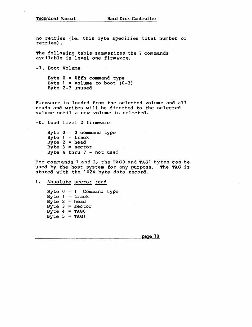
The following table summarizes the 7 commands available in level one firmware.
-1. Boot Volume
Byte 0 = Offh command type Byte 1 = volume to boot (0-3) Byte 2-7 unused
Firmware is loaded from the selected volume and all reads and writes will be directed to the selected volume until a new volume is selected.
-0. Load level 2 firmware
Byte 0 = 0 command type Byte 1 = track Byte 2 = head Byte 3 = sector Byte 4 thru 7 - not used
For commands 1 and 2, the TAGO and TAG1 bytes can be used by the host system for any purpose. The TAG is stored with the 1024 byte data record.
1 • Absolute sector read
Byte 0 = 1 Command type Byte 1 = track Byte 2 = head Byte 3 = sector Byte 4 = TAGO Byte 5 = TAG1
page 18

Technical Manual Hard Disk Controller
Byte 6 = number of retr ies + 1 the value of the high order bi t' of the retry byte needs to be a "1" if you want error correction. This should almost always be the case.
Byte 7 = 0
2. Absolute sector write
Byte 0 Byte 1 Byte 2 Byte 3 Byte 4 Byte 5 Byte 6
= = = = = = =
2 Command type track head sector TAGO TAGl number of retries + 1 the value of the high order bit of the retry byte needs to be "1" to request a "read after write check". The remaining 7 bi ts of the retry byte determine the number of retries.
Byte 7 = 0
* Command 2 must be followed by a lK block of bytes.
3. Load level two firmware from host (lK byte)
Byte 0 = 3 Command type Byte 1 thru 7 = 0 (not used)
* Command 3 must be followed by a block of bytes.
page 19
Technical Manual Hard Disk Controller
4. Format write (write sector 1 from INDEX)
Byte 0 = 4 Command type Byte 1 = track Byte 2 = head Byte 3 = sector Byte 4 = TAGO Byte 5 = TAG1 Byte 6 = number of retries + 1
If high order bit = 1, read after write check Byte 7 = 0
5. Get contents of HOC memory
Byte 0 = 5 Command type Byte 1 = 0 (not used) Byte 2 = low 8 bits from HOC Byte 3 = high 8 bits from HOC Byte 4 = low S bits of byte count Byte 5 = high 8 bits of byte count Byte 6 = not used Byte 7 = not used
Note---ROM command -1 is only implemented in . firmware version 2.2 or later.
Special Commands Commands 6-9 are used for spec ial tests and formatting.
page 20
Technical Manual Hard Disk Controller
Level two fi~are
Digital Microsystems, Inc. currently supports four operati~ systems, CP/M 1.4, CP/M 2.2, HiNet, arrl HIOOS.
The following table summarizes the 9 commands for CP/M 1.4 or 2.2 •
1 Oh. Warm start (No longer supported or used)
Byte 0 = 10h Comnarrl type Byte 1 = 0 for track 0 Byte 2 = 1 for head 1 Byte 3 = 1 for sector 1 Byte 4 = number of logical sectors required Byte 5 thru 7 not used
11h. CP/M read (128 byte) Byte 0 = 11 h Comnand type Byte 1 = sector (1 to 128) Byte 2 = track (low order byte) Byte 3 = track (high order byte) . Byte 4 thru 5 not used Byte 6 = number of retries + 1 Byte 7 .= 0
12h. CP/M write (128 byte) Byte 0 = 12h Comnarrl type Byte 1 = sector (1 to 128) Byte 2 = track (low order byte) Byte 3 = track (high order byte) Byte 4 thru 5 not used Byte 6 = number of retries + 1 Byte 7 = 0
page 21
Technical Manual Hard Disk Controller
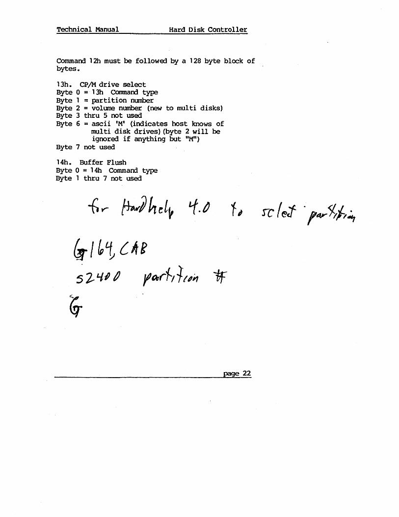
Command 1 2h must be followErl by a 1 28 byte block of bytes.
13h. CP 1M drive select Byte 0 =-13h Command type Byte 1 = partition number Byte 2 = volume number (new to multi disks) Byte 3 thru 5 not used Byte 6 = ascii 'M' (indicates host knows of
multi disk drives) (byte 2 will be ignored if anything but "M")
Byte 7 not used
14h. Buffer Flush Byte 0 = 14h Command type Byte 1 thru 7 not used
&1 ~t {Ae 5 ~ 'II I JltAJr~/ll'#1
page 22
Technical Manual Hard Disk Controller
15h. 1k read Byte 0 = 15h cannand type Byte 1 = sector (1 to 128) A 1 k disc sector will be returned which includes the CPM sector specifia:!. Most programs should insure that CPM sector mod 8 is 1. Byte 2 = track (low order byte) Byte 3 = track (high order byte) Byte 4 if true, (FFh) force a pre-read ~
if false, (Oh) no forced pre-reect"'1t Byte 5 not used ) Byte 6 = number of retries + 1 .. Byte 7 = 0 ~ ____
1 6h. 1 k wri te (NOT IMPLEMENTED)
17h. Assign a partition Byte 0 = 17h Comnand type Byte 1 thru 7 not usa:! Byte 8 thru 15 = Name Byte 16 thru 21 = Password (If PW is all O's it
will match regardless of actual password)
On return: Byte 0-= size byte or Offh if denied Byte 1 = partition ntnnber Byte 2 = control byte Byte3 = volume number (newtomulti-disks) Byte 4 thru 7 unused
page 23
Technical Manual Hard Disk Control ler
l8h. Get Volune Information Byte 0 = 18h Comnand type Byte 1 = ROM version Byte 2 = ROM reversion Byte 3 = finmware version Byte 4 = firmware reversion Byte 5 thru 7 unused
On return: Byte 0 = l8h Coomand echo Byte 1 = ran version number (all versions binary) Byte 2 = ram revision number Byte 3 = finmware version number Byte 4 = firmware revision number Byte 5 thru 6 unused
status
If status = 0 there follows 128 bytes, 32 bytes for each volume. Each volume's info is as follows:
Byte 0 = volume present (true or false) Byte 1 = current track for volume Byte 2 = tracks on volume Byte 3 = sector per track Byte 4 = head mask (disk type) Byte 5,6 = location of partition offset table Byte 7,8 = location of bad sector table Byte 9,10 = location of bad sector dirty flag Byte 11 = error in volume open during firmware
init (0 = no error) Byte 12 thru 21 = volume label, 10 chars of ascii Byte 22 thru 31 not used
page 24
Technical Manual Hard Disk Controller
19h. write cae error to last sector on disk Byte 0 = 19h Bytes 1 thru 7 unused
page 25
Technical Manual Hard Disk Controller
1.6. x Completion of a command Commands 1,2,11h,12h,13h,14h,15h, and 16h, result in the HOC returning a status block upon completion of the command or an interruption of the command due to an error. The status block will be a copy of the command block, with the following changes:
For commands 1 and 2, if bytes 1, 2, or 3 have been changed, the HOC has substituted a spare sector for a defective sector. The track byte will be 200 or 201 for a Shugart drive and 241 or 242 for a Fujitsu drive.
If the retry byte has been decremented, errors were encountered. If the byte is decremented to 0, the error is permanent. (see status byte).
Commands 11 and 15, (reads) will have a data block following the return status only if'no error occured. For command 15h, a 1K read, byte 5 will be· true {FFh) if the sector came from the buffer and false (Oh) if the sector was read directly from the hard disk.
page 26

Technical Manual Hard Disk Controller
Byte 7 will be "0" for a non-error return. A nonzero in byte 7 (the last byte) indicates' one of the following errors:
Hex Value of byte Problem
11 Write fault: Possible drive problem 12 Drive not ready 13 Internal timeout HOC problem 14 Read after write compare error 15 Unprocessed CRC error. ROM detected erro'r but
firmware error correcting code was not present. 16 Volume selected (command 13h) not present. 17 No index mark on disk. Indicates no power to
disk or disk not present. 18 Timeout while seeking a track. 19 Timeout while seeking track O. 20 Error in firmware init process 21 HOC cannot find sector header 22 Bad track, sector, or head assignment in header 23 Header checksum error 24 Track invalid (too big) -25 Head- invalid for drive 26 Sector invalid for drive 27 Invalid volume selected (command 13) 28 ·Bad firmware version 29 Duplicate volume label 30 CPM mapping error 31 Error occurred in flush (see note 2 below) 32 Partition invalid (too big) in select 40 Data CRC error 41 CRC error, correction successful 42 Non-correctable CRC error 80 Command error 91 Error saving 17K in format (HARDHELP) 92 Error restoring 17k in format (HARDHELP)
page 27

Technical Manual Hard Disk Controller
NOTE: A 41 h in byte 6 and a OOh in byte 7 of the status block indicates a CRC error occurred and was corrected.
NOTE 2: Error 31 will occur in response to a command 13 (CP/M dr ive select). The status of the problem is as follows:
Byte 0 = Command generating error Byte 1 = track Byte 2 = head Byte 3 = sector Byte 4 = block number (low order byte) Byte 5 = block number (high order byte) Byte 7 = ACTUAL ERROR Byte 8 = 31h
page 28

A. B C
1lA7 (,.h-') ..... P5h-8 .
&, MAO -7
." -0
."01 .....,., -30 I~H~ .... , -,
J.'Jt.'iJ HAo -2 0 I
ill' >J ~ "to'W (P3\,-3\)
ttl G'lrr:61
CO HDt (n":G) 5 ID7· ;
, -n ; :~l
eD7 tiD (Plh :t~
ntr tNF8! " " 4 " oe
ttl lNFe!
3 1117 pOt!
bsc.-2. I NrEIU=Ac..6
Z
A B c
D E
INTERFACE. l 'C.l 0lJrFA/
ro tD7: i A,h
eo~ '1'IL.S~7!
1C.' ~FAI
1Cl INFc./
1A' Z~S~TI
107 OllTF2./
INTERFACE 1 10, oUl'"FBI
1\
ro ~ DAShq!
J ID7 7'115313 5
ttT !NFS/
ICT INFC!
,AO ~AE.SETI
,A7 OUTF2./
D
F
1FIWCI (,»tool.) ' -, ~ :l . -, , -t UlliI'7 (n":,
n:1NAI (Plio-II)
lFlnlll (plf~-n)
I<UUErl (p2h-1n
1F2""1I (P2h-~I)
IF3tIBO (Plh·Z)
~ :! i :t
.1F31)97 (Plh=-'t
l:n~ATA.1 (l'lh-IS)
IFSStAT'6/ (Plh-17)
I.FIRESET/(plh-,,)
Ifl"MII (Plh-ZI)
F
DIGITAL MICROSYSTEMS
D ... TK. 't- 27 - 7~
HAR D DISK CONTROL lE R
HOST INTE.RFAC.Ei
G
D,,",WN n 1>. CPi~ Rmsm I-Ztf-'81
,
5
+
3
2
A B c D
, ,., DD. ------'-F,:-:O}'------fl J>.----- meuv Cpu- 2S)
p.:.---- H~SELII -2
ttl O!lrFF/---...... -,
»;:--___ HDSELU -~
5 "'" -----"---' »-"------ HtlSELBI -8
p=----- DIRt -zq
»-'------ STEP / -2.
t.:E)' -----------_ ~,j '"!I-----V1RT&~lEI -,.
" r~·AIT In
...... RT'PI\TJ.. ________ ~~~'~"'~'------Wtl. -~
~ -lA(",,"',,"'-, _____ WD- -4-0
+ 10+ lIItn\TE ,,-----RD4.\"TE/ -3" ,-b'-------"c· -~1.
IE3 RDCL.KI
+5,
lC.SJ"~ 5ECmR -------------,;<!I p,,-'----/+-- 5<0"1 -1~
·,o7 1>l>~
I>;;-+--f!--- ,"\)EX/ -10
'OT lNFE/
D~3 --+!.Q: f"--------''4' p"-+~-_+'---wRTFLTt -3~
3 DDZ __ --'--1.-<, 1-"'----------''4B'!>'-4--+'--- TRKo/ -3Z
'OT .,, P----------'~II>'-*--+'----SWlMPt -22
1>1>0 --+~~I_''-------''<l~~ ....... t__--t__-REAbY t -12
1<1 INFFI
'0' RW.K 2 ~• " r--~'----R<+ -~5
_______ ""I~ And
15'lIr ;; T \I~L_""" __ _ . - RC' -~~
~5!R" -~8 1 Allct
''',1'17 Rl>bATA/--------.!. 1~/fS- '3 6,7 '-_ ..... __ _ - _ R~- (Pld - 4q)
115 BuSY
1\ B c D
E F
DIGITAL MICROSYSTEMS
HARt:> DISK CONTROLLER DRIVE INTERFA<::.e:
E F Go
DRAW"'- n 1>, CDB B IIIYIHD 1-2.-' -1I'(
:3 &F3
H
5
3
2
A B
a
7
~.'
2
..- '''-'1.,-_._-,", ·our
1:1
c D
'-""',","I'"1"==r-__ ~~ __ ~~T'""...;;Ao;;.-..;A.;;. _______ ADl>R ~"5 "l.u
'"
El CLC."1'/+--_----t---,
., O\TrPCI ++---:---"<1'::::-' &1. Be ..
DO. "","~I
•• ORAS .~ c ...... • 3 DcAS os t ... I. &-IT'sYN.c.
tl VlIII.
<1 0,,",,-,
" DO 01 .. ., gt ., ., O?
97 PDeI
C
.. RAME>
.... .... II' AI:! ,.,.,.Z .... 081.13
K Bml M' 8YT'E1Z8 os BYrf2 D4- I3VTE2.S' .1 6'1TE't " 1Wl'E51'l Dr BYTES D4 IYTEtoli
05) t!MUX
Dl P.N(DJ
OS' 1J'{TC'1'.,,&'O'e;z.olle as" &m'3l. D2. 'I RAIl. D5' BoYTE6't ~a' . RAt3
..... " DS 'VY. _1 K :r3
e'fTIll 'f:" .,,..,,&
I"--NW'- SRA~I D4
I-'--NW~'Sc!J.s1 .4
t=--VVVV~';'''''/R I.
.20.0.
D
E F c. H I J
P1 DATA5uS -'_""~"" __ ~_~~~~~~I"" 3"2. .... II.Tlh\n ----"-/Hi" .... sO? ---2.t:JI
'I~
."
f"-~H-1H-1-t''tI'N'"y.!!-- SAD O~
p---'>-t1H-i+'YN'o/'-~- 'SAt Dot
1""-~I+I-t'''lv'WV'--f.L-< .. O'
p----'4-l-t'yN'O/,-L-SA. 0+
f-L----'-i...p"v'M"y':':"'-<M O' P---'+''W'N'o/'-'''-- &AS ~'"
f.L..---~~M~~-SA. D'
5 7
UPPER Z117
It,bCLK.1 31+ 12
E
J-4-, RbEC.C [1 Eet.OU"l'
SBi R'DDATAI
[~ R.tu'ec.1
D3: IN~A.'b~
:1"3 WPJ'GA'R
i~ ~: BC!'t B!llrt1-,HS Be.
CLCt-.iT
I' .. ..
F
381. Itb""TA' -------,
;u. """"«.1 ,-'---1+----,
-.v .Sv
't-tZ'I
" . 'JIIlSt"lfm;~'-_...J!!..j
DID
."
Oil
C.T INFDI' ------------------------,
17 ECCollT
Go, 5R'7
384 sa:noR -'-----::-----,
DI &7 OUfFCI
>P, Df S'fTEzst.. --r-;I\
eT OIJTFCI ------------,
L------+--GoTS'tN.C 1t3
02
weee , .. 1.' ___ --',-;;;-"\ IS' b'O"f"'" 'I,.. }"---'==---'
.. 1m'''. -fa i· DS &'tTC8 ~
'" OS c:I.At1e
C, H \ I
DS Dl
D7 07
WII,n.-~ Ifl,n,)l+
WP.TDATA 584
wAT6"'1'fJ 1'3
wRTEee/ Nl,H4,
J
L
7
5
3
2
DIGITAL MICR05YSTEMS t HAWN.., b.Coaa
~n. 4.13.7'\ UVIIIU )-Z,8-1r\
HARD DISK CONTROLLER DMWlNClNUIIUIDI
Cot-JTR.OL I OF3
/( l