technical guidance note (monitoring) sampling … · sampling requirements for stack emission ......
TRANSCRIPT

Technical Guidance Note (Monitoring)
M1
Sampling requirements for stack emission monitoring
Environment Agency Version 8
August 2017


Amendments
Version
number
Date Amendment
8 August 2017
Updated information on inspections of permanent platforms (section 9.7.7.1)
Status of this document This TGN may be subject to review and amendment following publication. The most recent version of this note is available at:
www.mcerts.net
Feedback If you have any comments on this standard please contact our National Customer Contact Centre at: Email: [email protected]

Foreword Purpose This Technical Guidance Note (TGN) on sampling requirements for monitoring stack emissions to air is one of a series providing guidance to our staff, monitoring contractors, industry and other parties interested in stack emission monitoring. It is also a guidance document in support of our Monitoring Certification Scheme (MCERTS) and Operator Monitoring Assessment (OMA). It provides guidance on European standard BS EN 15259:2007 Requirements for measurement sections and sites and for the measurement objective, plan and report. It focuses on the parts of the standard that deal with measurement sections and sites. This TGN also provides guidance on risk management in stack emission monitoring. Throughout the document, references to sampling from stacks should be interpreted as also meaning sampling from vents, ducts and flues, unless otherwise stated.

Contents
1. Monitoring guidance and MCERTS ............................................................. 1 2. EN 15259 – Requirements for measurement sections and sites and for the measurement objective plan and report ................................................... 1 3. Designing a representative measurement location ................................... 2 Box 3.1 Definitions of important terms in stack emission monitoring ................... 2 4. Principles of representative sampling ........................................................ 3 5. Periodic sampling using grid measurements ............................................. 4 5.1 Grid measurement positional requirements ................................................... 4 5.2 Criteria for locating the sampling plane ......................................................... 4 5.3 Surveying the proposed sampling plane ....................................................... 5 5.4 Preliminary velocity survey ............................................................................ 5 5.5 Number of sampling points ........................................................................... 6 5.6 Position of sampling points along the sample lines ....................................... 6 6. Representative sampling of gases .............................................................. 6 7. Sampling requirements: continuous emissions monitoring systems ...... 7 8. Sampling facilities for stack-emission monitoring .................................... 7 8.1 Permanent platforms ..................................................................................... 7 8.2 Space for the equipment and personnel ........................................................ 7 8.3 Means of entry into the stack (measurement ports) ....................................... 8 8.6 Sampling facilities for periodic monitoring of gases ....................................... 8 8.7 Sampling facilities for CEMs ......................................................................... 8 8.8 Essential services ......................................................................................... 9 8.9 Installing and upgrading sampling platforms at existing stacks...................... 9 8.10 Alternatives to permanent platforms ............................................................ 9 9. The risk-management approach to site work ............................................. 9 9.1 Safety has the highest priority ....................................................................... 9 9.2 Prominent hazards encountered when stack-emission monitoring .............. 10 9.3 The risk-assessment process...................................................................... 11 9.4 Responsibilities ........................................................................................... 12 9.5 When to carry out a risk assessment .......................................................... 12 9.6 Getting the operator involved ...................................................................... 13 9.7 Working at heights ...................................................................................... 13 Annex 1 - Check sheet of sample facility requirements for plant designers / operators ......................................................................................................... 19 Annex 2 Examples of platforms and sampling ports ................................... 22 References ...................................................................................................... 27

TGN M1, Version 8, August 2017 Page 1 of 27
1. Monitoring guidance and MCERTS This Technical Guidance Notes (TGNs) covers sampling and safety requirements for stack emission monitoring. It is one of a series of TGNs in the ‘M’ series providing guidance on regulatory monitoring and support to our Monitoring Certification Scheme MCERTS. MCERTS for manual stack emission monitoring (see box 1.1) provides for the assessment of the quality and reliability of organisations, and the competence of individuals carrying out stack emission monitoring against published performance standards for organisations1 and personnel2.
2. EN 15259 – Requirements for measurement sections and sites and for the measurement objective plan and report Comité Européen de Normalisation (CEN) standard BS EN 152593 is a European standard that is of importance to plant designers, plant operators and stack emission monitoring organisations. In summary BS EN 15259:
specifies requirements for stack emission monitoring measurement locations
applies to both periodic measurements and to continuous emission measurement systems (see Box 2.1)
outlines the sampling strategy required to obtain a representative sample This TGN provides guidance on meeting the requirements of BS EN 15259. It does not repeat text, tables or diagrams from BS EN 15259; instead it refers to the relevant sections of this standard. It is therefore strongly recommended that the reader has a copy of BS EN 15259.
Box 1.1 MCERTS
MCERTS is our Monitoring Certification Scheme for instruments, monitoring and analytical services. The scheme is built on proven international standards and provides industry with a framework for choosing monitoring systems and services that meet our performance specifications. MCERTS reflects the growing requirement for regulatory monitoring to meet European and international standards. It brings together relevant standards into a scheme that can be easily accessed by manufacturers, operators, regulators and laboratories. Further information on MCERTS is available at www.mcerts.net
TGN M1, Version 8, August 2017 Page 2 of 27
3. Designing a representative measurement location Suitable measurement sections and measurement sites are necessary to obtain reliable and comparable emission measurement results. Therefore, appropriate measurement sections and sites should be planned when designing a plant. Terms related to the measurement section and site are given in Box 3.1
Emission measurements require appropriate measurement ports and working platforms. Therefore, the installation of measurement ports and working platforms should be taken into account at the planning phase of a measurement section.
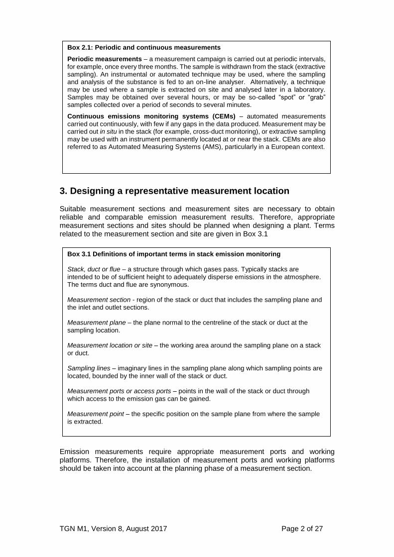
Box 2.1: Periodic and continuous measurements
Periodic measurements – a measurement campaign is carried out at periodic intervals, for example, once every three months. The sample is withdrawn from the stack (extractive sampling). An instrumental or automated technique may be used, where the sampling and analysis of the substance is fed to an on-line analyser. Alternatively, a technique may be used where a sample is extracted on site and analysed later in a laboratory. Samples may be obtained over several hours, or may be so-called “spot” or “grab” samples collected over a period of seconds to several minutes.
Continuous emissions monitoring systems (CEMs) – automated measurements carried out continuously, with few if any gaps in the data produced. Measurement may be carried out in situ in the stack (for example, cross-duct monitoring), or extractive sampling may be used with an instrument permanently located at or near the stack. CEMs are also referred to as Automated Measuring Systems (AMS), particularly in a European context.
Box 3.1 Definitions of important terms in stack emission monitoring Stack, duct or flue – a structure through which gases pass. Typically stacks are intended to be of sufficient height to adequately disperse emissions in the atmosphere. The terms duct and flue are synonymous. Measurement section - region of the stack or duct that includes the sampling plane and the inlet and outlet sections. Measurement plane – the plane normal to the centreline of the stack or duct at the sampling location. Measurement location or site – the working area around the sampling plane on a stack or duct. Sampling lines – imaginary lines in the sampling plane along which sampling points are located, bounded by the inner wall of the stack or duct. Measurement ports or access ports – points in the wall of the stack or duct through which access to the emission gas can be gained. Measurement point – the specific position on the sample plane from where the sample is extracted.

TGN M1, Version 8, August 2017 Page 3 of 27
4. Principles of representative sampling The mass concentration of a stack emission is the concentration of the measured component averaged over the cross section of the stack, averaged over a defined time period. Concentration distributions may differ across a stack and over time. If concentration and / or velocity profiles, which are variable in space and time occur, the emissions are determined as the integral for time and space over the stack area. This means that the average concentration and velocity at several measurement points across a stack may need to be determined. For gases carrying particulates, inertial effects introduced by gravity and the duct geometry lead to the particles being unevenly distributed in the stack. Samples must be obtained from multiple sample points (a grid measurement) across the sampling plane to give an overall average of the particulate emission. Rules have been developed specifying where these sampling points should be located. Rules have also been developed for determining the flow criteria that a cross section must comply with in order to carry out a grid measurement – these rules are based on having an even flow profile.
For extractive particulate methods, the sample must be collected isokinetically (see Box 4.1) using a grid measurement approach. Stack gases may be non-homogeneous due to differences in chemical composition, or differences in temperature and velocity, which may lead to stratification and swirling. However, simplifications for gas sampling can be made if the concentration does not change over the cross section of the stack. Therefore, where the measurement is of concentrations of gaseous species alone, a sampling location can be chosen that does not have to take into account the requirements to measure flow and particulates. This means requirements on designing a measurement section to measure gas concentrations alone can be less stringent than for measuring flow or particulates. Also, provided the gases are well mixed the sampling approach is more straightforward because single point sampling may be carried out rather than grid sampling. However, these simplifications for gas sampling can only be made if it can be proven that the stack gas is homogenous (i.e. well mixed). If the gases are not well mixed, it is necessary to sample the gases using a grid measurement technique. When a grid measurement technique is required it is necessary to be able to measure the velocity at several points across the sample plane. This means that it is advisable to consider, at the design stage, the possibility of the gases being heterogeneous. Also, if the mass emission rate of a gas is to be calculated, the gas volumetric flow rate will need to be measured; this will require velocity measurements to be made at several points across the sampling plane using a grid measurement approach. Some pollutants, for example, metals and dioxins, are present in both particulate and vapour phases. Other pollutants for example, hydrogen chloride, may be present in an aerosol phase and vapour phase. Aerosols are normally treated as particulates. In all such cases grid measurement sampling is required.
TGN M1, Version 8, August 2017 Page 4 of 27
5. Periodic sampling using grid measurements 5.1 Grid measurement positional requirements BS EN 15259 details the positional requirements for carrying out a grid measurement. This approach is used for:
sampling particulates
sampling multiphase pollutants
sampling using wet chemistry when droplets are present
velocity measurements for reporting mass emission
sampling gases that are distributed heterogeneously, due to effects, such as stratification
determining a representative sample location for CEMs
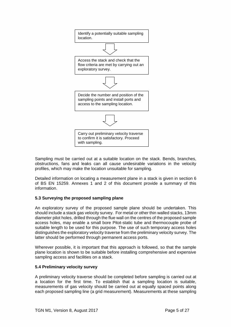
5.2 Criteria for locating the sampling plane The general approach for locating a sample plane for grid measurements can be summarised as:
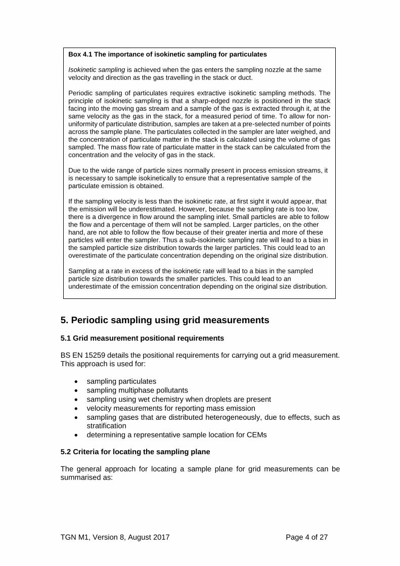
Box 4.1 The importance of isokinetic sampling for particulates Isokinetic sampling is achieved when the gas enters the sampling nozzle at the same velocity and direction as the gas travelling in the stack or duct. Periodic sampling of particulates requires extractive isokinetic sampling methods. The principle of isokinetic sampling is that a sharp-edged nozzle is positioned in the stack facing into the moving gas stream and a sample of the gas is extracted through it, at the same velocity as the gas in the stack, for a measured period of time. To allow for non-uniformity of particulate distribution, samples are taken at a pre-selected number of points across the sample plane. The particulates collected in the sampler are later weighed, and the concentration of particulate matter in the stack is calculated using the volume of gas sampled. The mass flow rate of particulate matter in the stack can be calculated from the concentration and the velocity of gas in the stack. Due to the wide range of particle sizes normally present in process emission streams, it is necessary to sample isokinetically to ensure that a representative sample of the particulate emission is obtained. If the sampling velocity is less than the isokinetic rate, at first sight it would appear, that the emission will be underestimated. However, because the sampling rate is too low, there is a divergence in flow around the sampling inlet. Small particles are able to follow the flow and a percentage of them will not be sampled. Larger particles, on the other hand, are not able to follow the flow because of their greater inertia and more of these particles will enter the sampler. Thus a sub-isokinetic sampling rate will lead to a bias in the sampled particle size distribution towards the larger particles. This could lead to an overestimate of the particulate concentration depending on the original size distribution. Sampling at a rate in excess of the isokinetic rate will lead to a bias in the sampled particle size distribution towards the smaller particles. This could lead to an underestimate of the emission concentration depending on the original size distribution.
TGN M1, Version 8, August 2017 Page 5 of 27
Sampling must be carried out at a suitable location on the stack. Bends, branches, obstructions, fans and leaks can all cause undesirable variations in the velocity profiles, which may make the location unsuitable for sampling. Detailed information on locating a measurement plane in a stack is given in section 6 of BS EN 15259. Annexes 1 and 2 of this document provide a summary of this information. 5.3 Surveying the proposed sampling plane An exploratory survey of the proposed sample plane should be undertaken. This should include a stack gas velocity survey. For metal or other thin walled stacks, 13mm diameter pilot holes, drilled through the flue wall on the centres of the proposed sample access holes, may enable a small bore Pitot-static tube and thermocouple probe of suitable length to be used for this purpose. The use of such temporary access holes distinguishes the exploratory velocity traverse from the preliminary velocity survey. The latter should be performed through permanent access ports. Wherever possible, it is important that this approach is followed, so that the sample plane location is shown to be suitable before installing comprehensive and expensive sampling access and facilities on a stack. 5.4 Preliminary velocity survey A preliminary velocity traverse should be completed before sampling is carried out at a location for the first time. To establish that a sampling location is suitable, measurements of gas velocity should be carried out at equally spaced points along each proposed sampling line (a grid measurement). Measurements at these sampling
Identify a potentially suitable sampling location.
Access the stack and check that the flow criteria are met by carrying out an exploratory survey.
Decide the number and position of the sampling points and install ports and access to the sampling location.
Carry out preliminary velocity traverse to confirm it is satisfactory. Proceed with sampling.
TGN M1, Version 8, August 2017 Page 6 of 27
points must demonstrate that the gas stream at the sampling plane meets the flow stability criteria requirements. If the results do not conform to the flow stability criteria, another sample location should be found. Detailed information on the required flow criteria is given in section 6 of BS EN 15259. 5.5 Number of sampling points The number of sampling points required is determined by the size of the stack. The minimum number of sampling points and sample lines are given in section 8 of BS EN 15259. 5.6 Position of sampling points along the sample lines The sampling plane is divided into equal areas and sampling is carried out from points in the centres of these areas. Further details are provided in section 8 of BS EN 15259.
6. Representative sampling of gases Gases can be sampled using a grid measurement approach. The sampling points in the grid are determined in the same way as for flow stability checks and isokinetic sampling. However, when an instrumental technique is used the length of time spent at each point is proportional to the concentration of the gas in the stack and the velocity at the sample point. As gases are often well mixed, it may be possible to prove that a grid measurement may not be required and that sampling from a single point may be carried out. This is done by assessing spatial and temporal variations in the gas concentration. The procedure for doing this is given in section 8 of BS EN 15259. If the distribution is heterogeneous, it may still be possible to sample from a single point provided that a single representative point can be found. The approach is based on assessing whether the variations in concentration across the stack are within the allowable measurement uncertainty. The procedure to determine if a representative point can be found is given in section 8 of BS EN 15259. If a representative point cannot be found due to the gas being heterogeneous, grid measurements must be carried out. Where grid measurements are required it is necessary to measure the velocity at each sample point, so that representative sampling can be achieved. Once the homogeneity test has been completed it does not need repeating unless there is a significant change in the fuel type, structure of the stack or process abatement systems. Further information on the application of the homogeneity test is available in Environment Agency Method Implementation Document (EA MID) for EN 152594.
TGN M1, Version 8, August 2017 Page 7 of 27
7. Sampling requirements: continuous emissions monitoring systems In many applications, the calibration of CEMs is established by comparison with simultaneous measurements obtained using a periodic standard reference method. Further information is contained in EN 141815 and TGN M206. Wherever possible, the CEMs and periodic monitoring locations should be in close proximity. Therefore, the same location requirements apply to periodic monitoring and CEMs. Permanently installed CEMs are usually restricted to sampling at a single point, or along a single line-of-sight. These sampling points or lines must be located, so that a representative sample of the measurand is obtained. They must be positioned so as not to obstruct, or be affected by, sampling probes used to perform periodic measurements. For point source in-situ or extractive CEMs, it is necessary that the measurement point is representative of the mass flow density of the determined being measured, and often also the oxygen volume fraction. The procedure for determining a representative sampling point for a CEM, along with a worked example, is given in section 8 of BS EN 15259 and EA MID for EN 15259.
8. Sampling facilities for stack-emission monitoring 8.1 Permanent platforms Permanent platforms must be provided with handrails and kick-boards that meet the requirements of the Workplace (Health, Safety and Welfare) Regulations 1992, (Regulation 13) for permanent platforms and the Health and Safety in Construction Regulations (HS (G) 150) for temporary platforms. Sampling from roofs or the tops of arrestment equipment, vessels and ducts is unacceptable unless they have been assessed as being suitable by meeting the requirements for platforms described in this TGN and The Work at Height Regulations 2005 (WAHR), Regulation 8 and Schedule 37. Protection from adverse weather may be desirable for an exposed sampling position. However, it should be recognised that any protective cladding installed at high levels will affect wind loading on the stack and will be vulnerable to damage during high winds. It may be preferable to ensure that sampling at elevated positions is only carried out in periods of relatively calm weather as the installation of an enclosure at the sampling platform does not remove the hazard of transporting equipment and personnel to the platform under unfavourable conditions. Annex 1 of this document provides a summary of the information on platforms and sampling facilities in BS EN 15259. 8.2 Space for the equipment and personnel Platforms must have a sufficient working area to manipulate the sampling probe and operate the measuring instruments, without equipment overhanging guardrails.

TGN M1, Version 8, August 2017 Page 8 of 27
Annex 1 of this document provides a summary of the information on platform sizes in BS EN 15259.
Example diagrams of platform designs are shown in Annex 2.
8.3 Means of entry into the stack (measurement ports) Measurement ports shall be big enough for the insertion and removal of the equipment used, and to allow the measurement points to be reached. Typical arrangements of access fitments are shown in Annex 2. 8.4 Sampling facilities for periodic monitoring using multiphase sampling techniques Multiphase sampling uses a combination of isokinetic and gas phase sampling techniques to measure determinands in both the particulate and gas phase. Determinands include metals and trace organic micro pollutants, such as dioxins/furans, PCBs, and PAHs. Multiphase sampling equipment cannot be used, without deviations from standard methods, on horizontal circular ducts, with an internal diameter of greater than 0.35m, because the orientation of the measurement ports prevents access to the measurement points. If a horizontal duct is used, it should be rectangular, rather than circular, as this will allow access to the required measurement points. 8.5 Sampling facilities for periodic monitoring of PM10 and PM2.5
The dimensions of the measurement ports should allow straight insertion of the PM10 and PM2.5 sampling equipment without any contact with the inner stack walls. Due to the size and orientation of the sampling equipment (an in-stack sampling system with a straight entry nozzle), this can be most easily achieved using a rectangular measurement port, as described in BS EN 15259. 8.6 Sampling facilities for periodic monitoring of gases Access and facilities requirements for gases alone are usually less demanding than for particulates. In practice, meeting the requirements for particulates will also satisfy the requirements for gases. When gas concentrations only are to be monitored, smaller measurement ports than those specified for particulates may be possible. 8.7 Sampling facilities for CEMs When designing a platform for CEMs, access and facilities are required to enable:
calibration by periodic monitoring
routine maintenance and operational functional checks, such as span and zero checks to be carried out
As CEMs require calibration by periodic monitoring the access and facilities should, as a minimum, comply with the requirements for particulates and gases respectively.
TGN M1, Version 8, August 2017 Page 9 of 27
8.8 Essential services Details of essential services, such as electricity supply, lifting equipment, ventilation and lighting are provided in Annex 1. A sampling monorail may be attached above the measurement ports to enable certain designs of sampling equipment to be supported.
8.9 Installing and upgrading sampling platforms at existing stacks It is sometimes necessary to retrofit new platforms or upgrade platforms on existing stacks. It must be borne in mind that the original design of the stack may not have taken such changes into account. The installation or extension of fixed ladders and gantries to an existing stack will bring about a significant increase to the total load (especially wind load) on the structure. This effect may be particularly significant on stacks with small diameters, as they must support structures that meet the minimum size requirement specified in this TGN. When retrofitting fixed ladders and platforms to a stack an appropriately qualified engineer* should be engaged to carry out a design check of all components, including foundations, to ensure that it is capable of bearing the increased load. To carry out this assessment, full design details of both the existing structure and the proposed sampling platforms and access ladders must be available. It is also likely that the engineer will require the stack to be inspected by a competent specialist contractor to ensure that deterioration has not occurred to the overall stability of the structure. If necessary, it may be possible to carry out minor strengthening works to an existing structure to accommodate additional load, although there is a limit to the effectiveness of this approach. If the changes to the platform are supported by the existing structure then the requirement for inspection of the platforms prior to use may well need to be extended to the stack itself. 8.10 Alternatives to permanent platforms Industrial processes are regulated by Environmental Permitting Regulations (EPR). These place requirements on an operator to provide a permanent means of access to enable monitoring to be carried out at specified release points. However, in exceptional circumstances, at an old installation, where limited access prevents the installation of a permanent platform, temporary structures may be used, provided it is fully justified by the operator and the sampling team.
9. The risk-management approach to site work 9.1 Safety has the highest priority Safety must be considered at the earliest point in the monitoring strategy and must be given the highest priority. For example, a modification to the sampling position that would theoretically provide a technical improvement must not proceed if it introduces an unacceptable safety risk.
*Details of qualified engineers and specialist inspection contractors can be obtained from trade associations such as The Association of Technical Lightning and Access Specialists (www.atlas-1.org.uk).

TGN M1, Version 8, August 2017 Page 10 of 27
There are many hazards associated with stack monitoring. It is recommended that, as a minimum, the hazards described in section 9.2 of this TGN should be included in a risk assessment. However, there may be other hazards - every site is different. Detailed information is also provided in the Source Testing Association’s (STA) booklet Risk Assessment Guide: Industrial-emission Monitoring (see box 9.1).
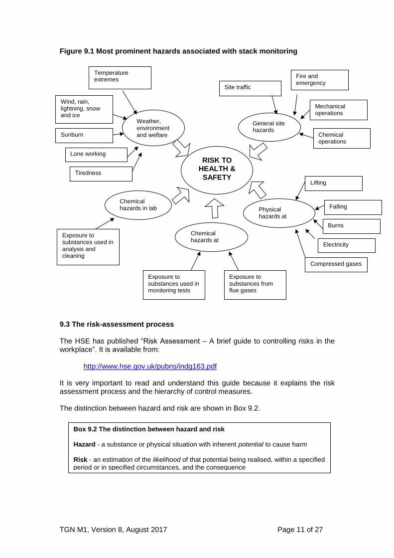
The focus of this section is on periodic monitoring, as it requires a considerable amount of manual work on site. However, the principles apply equally when carrying out work on CEMs, for example, during installation, maintenance and calibration. 9.2 Prominent hazards encountered when stack-emission monitoring The most prominent hazards are shown in Figure 9.1. This is not an exhaustive list and there may be other hazards. Every site is different.
Box 9.1 STA Risk Assessment Guide: Industrial-emission Monitoring The Source Testing Association (STA) is a trade association based in the UK. It is for organisations involved in stack emissions monitoring. The members of the STA have developed an Industrial risk assessment guide (known as the “yellow book”). Reporting accidents and near misses It is strongly recommended that information about accidents and near misses are reported to the STA. Knowledge of these, however minor they may appear, helps prevents future accidents occurring.
TGN M1, Version 8, August 2017 Page 11 of 27
Figure 9.1 Most prominent hazards associated with stack monitoring
9.3 The risk-assessment process The HSE has published “Risk Assessment – A brief guide to controlling risks in the workplace”. It is available from:
http://www.hse.gov.uk/pubns/indg163.pdf
It is very important to read and understand this guide because it explains the risk assessment process and the hierarchy of control measures. The distinction between hazard and risk are shown in Box 9.2.
Box 9.2 The distinction between hazard and risk Hazard - a substance or physical situation with inherent potential to cause harm Risk - an estimation of the likelihood of that potential being realised, within a specified period or in specified circumstances, and the consequence
RISK TO HEALTH &
SAFETY
General site hazards
Weather, environment and welfare
Site traffic
Fire and emergency
Physical hazards at stack
Chemical hazards at stack
Compressed gases
Sunburn
Temperature extremes
Wind, rain, lightning, snow and ice
Mechanical operations
Chemical operations
Lifting
Falling
Electricity
Chemical hazards in lab
Exposure to substances from flue gases
Exposure to substances used in monitoring tests
Exposure to substances used in analysis and cleaning
Lone working
Burns
Tiredness
TGN M1, Version 8, August 2017 Page 12 of 27
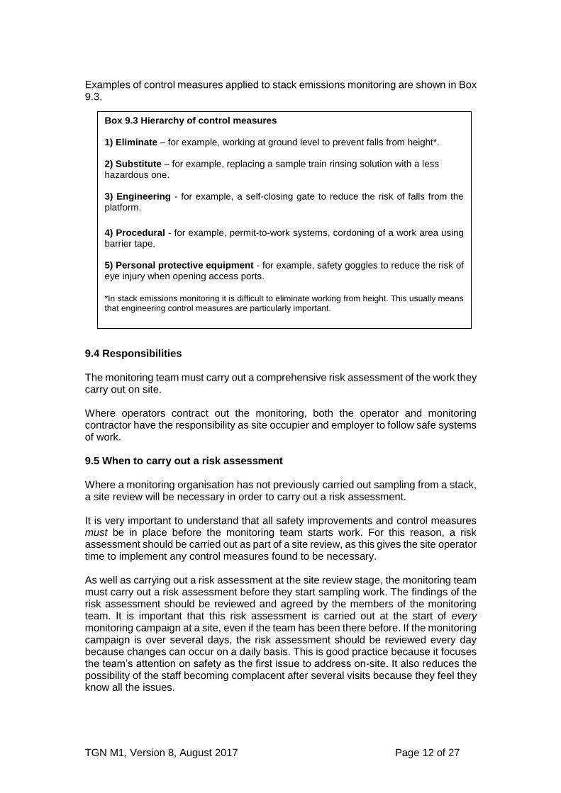
Examples of control measures applied to stack emissions monitoring are shown in Box 9.3.
9.4 Responsibilities The monitoring team must carry out a comprehensive risk assessment of the work they carry out on site. Where operators contract out the monitoring, both the operator and monitoring contractor have the responsibility as site occupier and employer to follow safe systems of work. 9.5 When to carry out a risk assessment Where a monitoring organisation has not previously carried out sampling from a stack, a site review will be necessary in order to carry out a risk assessment. It is very important to understand that all safety improvements and control measures must be in place before the monitoring team starts work. For this reason, a risk assessment should be carried out as part of a site review, as this gives the site operator time to implement any control measures found to be necessary. As well as carrying out a risk assessment at the site review stage, the monitoring team must carry out a risk assessment before they start sampling work. The findings of the risk assessment should be reviewed and agreed by the members of the monitoring team. It is important that this risk assessment is carried out at the start of every monitoring campaign at a site, even if the team has been there before. If the monitoring campaign is over several days, the risk assessment should be reviewed every day because changes can occur on a daily basis. This is good practice because it focuses the team’s attention on safety as the first issue to address on-site. It also reduces the possibility of the staff becoming complacent after several visits because they feel they know all the issues.
Box 9.3 Hierarchy of control measures 1) Eliminate – for example, working at ground level to prevent falls from height*. 2) Substitute – for example, replacing a sample train rinsing solution with a less hazardous one. 3) Engineering - for example, a self-closing gate to reduce the risk of falls from the platform.
4) Procedural - for example, permit-to-work systems, cordoning of a work area using barrier tape. 5) Personal protective equipment - for example, safety goggles to reduce the risk of eye injury when opening access ports.
*In stack emissions monitoring it is difficult to eliminate working from height. This usually means that engineering control measures are particularly important.

TGN M1, Version 8, August 2017 Page 13 of 27
9.6 Getting the operator involved When the monitoring team arrives on-site, its first task must be to conduct the risk-assessment. If the team has not worked on the site before, the operator’s representative should accompany them as they make the assessment for reasons of safety and to provide knowledge of specialised site-specific issues (for example, process conditions, escape routes). It is not always necessary for the team to be accompanied during the risk assessment when they return for repeat visits. However, whether it is the team’s first visit to the site or a repeat visit, the operator’s representative should be briefed on the findings of the completed risk assessment. This will give the operator the opportunity to raise any additional issues of concern, and comment on the findings of the assessment and the control measures the monitoring team has decided will be necessary. If the operator has any relevant comments, these should be considered. They can be incorporated into the assessment and its findings if they reduce the risk further. When the site work is finished, any relevant comments should be noted on the risk assessment based on any lessons learnt. This will be useful for the next visit. 9.7 Working at heights Due to technical reasons, it is usually necessary to carry out stack emission monitoring at height. Falls from height is the number one cause of fatalities at work. Falls from heights can occur from steps, ladders, platforms, scaffolding and roofs. Working at heights may also affect people in the area below where the work is taking place. Falling objects, such as equipment and tools can strike a person causing serious injuries. The WAHR 20057 are legally binding regulations that must be complied with. A summary of these regulations are provided below. The HSE provide information on working at height at the following: http://www.hse.gov.uk/work-at-height/index.htm 9.7.1 Organisation Every employer must ensure that work at height is:
properly planned by a competent person
appropriately supervised
carried out in a safe manner There is also a requirement to plan for emergencies and rescue. Therefore, an employer should have a rescue plan should something go wrong when working at height. This plan should consider what to do after a fall or if a medical emergency occurs without a fall. For example, what provisions are in place to get an unconscious person down from a platform that is accessed by vertical ladders only?
TGN M1, Version 8, August 2017 Page 14 of 27
The rescue plan should consider:
what equipment is available?
is stretcher access feasible, when stairs, ladders or hatches are present?
does the site have its own rescue team?
what are the evacuation procedures?
how long will a rescue take?
can it be done, ideally, without relying on the emergency services (fire brigade)?
9.7. 2 Competence and training To demonstrate that the work is planned by a competent person, it is necessary to have specific training. Training should include attending relevant courses, such as a working at height course and a lifting and slinging course. While undergoing training, employees should be supervised by a competent person. 9.7.3 Avoidance of risks The regulations require the use of the following strict hierarchy of control:
avoid the need to work at height
prevent the fall
mitigate the fall Due to technical reasons, it is usually not possible to avoid working at height when carrying out stack emission monitoring. This means the next best hierarchy of control is to prevent the fall. Preventing a fall requires the use of engineering control devices, such as handrails. These controls are known a collective passive protection. Vertical ladders do not have engineering control measures in place. Therefore, the use of personal protection (work restraint) systems is important for preventing falls from vertical ladders. These systems may be installed on site on a permanent basis by the operator or on a temporary basis by those doing the work. They are simple to use, they do not require specialised inspection regimes and they do not have to comply with specific standards that are required for fall arrest systems. It is important to understand that work restraint systems are different from fall arrest systems. A work restraint system ensures that the user cannot reach a position from which they can fall. Fall arrest systems are used to stop people being injured after they have fallen. Fall arrest systems are a method of last resort and are not considered appropriate for stack emission monitoring (that is the sampling location should have sufficient controls in place to prevent falls from occurring). An exception to this is a ‘double lanyard’ fall-arrest system, which can be used when accessing platforms from vertical ladders. Fall arrest systems require specialist training and highly technical equipment that must be inspected regularly by a competent person. These requirements are covered by a number of international standards, which must be complied with. For the requirements on personal protection systems see WAHR 2005 Regulation 8, Schedule 57. Where fixed vertical ladders, leading to a platform, do not have protection systems in place, using them as a means of access needs to be justified by a risk assessment. Under these circumstances, it is necessary to rely on behavioural safety because
TGN M1, Version 8, August 2017 Page 15 of 27
there is no control measure fitted to prevent falling. In these circumstances, the individuals are being relied upon to behave in a safe manner. This includes measures such as:
cleaning footwear adequately
maintaining three points of contact on the vertical ladder
resting adequately on midway platforms
checking rungs are clean and free from oil and grease For requirements on ladders see WAHR 2005 Regulation 8 Schedule 67. The HSE have published “Safe use of ladders and step ladders – a brief guide”. This is available from:
http://www.hse.gov.uk/pubns/indg455.htm 9.7.4 Fragile surfaces The employer must take suitable and sufficient steps to prevent any person from falling through any fragile surface. This requires coverings, guard rails and warning notices. 9.7.5 Falling objects It is necessary to take steps to prevent the fall of any material or objects. The following controls are examples of appropriate control measures:
do not take equipment up unless necessary (for example, keeping a manual sample train meter box at ground level with an umbilical line to the platform is good practice)
use of toe boards
tie off equipment 9.7.6 Danger area The danger area refers to the following locations:
where there is a risk of a person falling
where there is a risk of a person being hit by a falling object Where there is a risk of being hit by a falling object, it is a requirement to provide clear indication of the danger area. This is done by cordoning off the area below and using men working overhead signs to create an exclusion area. A major risk of falling equipment is caused by having to lift equipment to the working platform. Ideally there should be a well maintained permanently installed lifting system. However, if the platform does not have a permanently installed lifting system the stack emission monitoring team will have to use their own system. There is a wide choice of portable systems available. Lifting systems must use non-stretch static rope. There is a statutory requirement for them to be thoroughly inspected every 12 months. They should also be inspected pre-use or following any abnormal event. Training is required to be able to carry out an inspection of a lifting system. It is also very important for stack emission monitoring personnel to attend a lifting and slinging course. The lifting systems should be supported by a structure that has been assessed as suitable to support the lifting of equipment (most handrails are not suitable for this purpose). The lifting system should also be designed so that it is not necessary to lean
TGN M1, Version 8, August 2017 Page 16 of 27
over handrails when lifting equipment. A work restraint system may also be beneficial when handling loads over a handrail. 9.7.7 Platforms and access 9.7.7.1 Permanent platforms Permanent platforms are classed as existing places of work. They are covered by section 6 (4) (a) and Schedule 1 of the Work at Height Regulations. They are defined as a permanent part of the fabric of a building or structure. They are also covered by Section 4 (of the Health and Safety at Work Act 19748), which requires proportionate inspection by someone competent. This is not necessarily a mechanical or structural engineer but would be for the duty holder to decide. If the duty holder has doubts about what is required they could seek advice from the likes of the manufacturer, installer or a professional. Periodic inspections are carried out to assess the structural integrity of platforms and any supports and attachments. The inspections also includes the effects of weathering, corrosion and damage. The frequency and comprehensiveness of inspections are commensurate with the risk of failure and serious injury. For example, a steel platform at height and in a corrosive atmosphere may have more frequent and thorough inspections than a low platform in a normal atmosphere. Records of inspections should be made available for the monitoring team to check before they ascend to the work area. The following provides an inspection regime for working platforms and associated guard-rails, barriers, toe-boards and ladders:
after assembly/installation but before use;
a periodic inspection at suitable intervals, based on exposure to conditions causing deterioration; and
at each time an exceptional circumstance has occurred, which is liable to jeopardise its safety
It is also important that a prior to use check is carried out. This should be done by each person every time they use the platform. This is not a formal inspection and does not need to be recorded. This prior to use check should take account of factors, such as:
Ladders: are they secure, with no bolts missing, and free from corrosion and grease?
Handrails: are they secure, with no bolts missing and free from corrosion?
Floor plates: are they fixed in place, with no bolts missing and free from corrosion?
Access hatch: are they closed when not in use? 9.7.7.2 Scaffold Temporary, scaffold platforms should be constructed to a specific minimum Scafftag© category of “heavy duty” or meet the requirements stated in the monitoring standard. Special or masonry independent tied scaffold would normally be sufficient. Temporary platforms should be tied to, or supported by, a permanent structure. Scaffold should meet the same size requirements as specified for permanent platforms.

TGN M1, Version 8, August 2017 Page 17 of 27
Scaffolding must be inspected before use. For scaffolding, a properly completed and dated Scafftag© is one means of demonstrating and recording this inspection. As with permanent platforms the user should carry out a prior to use check each time they use it. As a minimum they should check:
the ladder is secured
there are no missing rails
there are no missing toe boards
there are no unsecured boards
the access points are gated
it meets the size and weight requirements
its secured to a structure
there are no hazardous uncapped pole ends, for example, at access points Requirements on scaffolding are in WAHR 2005 Regulation 8 and Schedule 37. HSE guidance on scaffolding is available from:
http://www.hse.gov.uk/construction/safetytopics/scaffoldinginfo.htm 9.7.7.3 Mobile elevated work platforms Sampling from mobile elevated work platforms (MEWPs) is unacceptable for the vast majority of stack emissions monitoring work because of the:
amount of space required to carry out stack emissions monitoring
amount of stack emissions monitoring equipment required
weight of stack emission monitoring equipment
amount of stack emissions monitoring equipment that requires support
requirement to connect stack emissions monitoring equipment to ground level
requirement for personnel to have regular access to and from the sample location
length of time that samples are taken for
number of people involved in a monitoring campaign
requirement for them to meet the same size requirements specified for permanent platforms
Due to the reasons given above it is only acceptable to use MEWPs to carry out monitoring work when the majority of the equipment is kept at ground level. This usually prevents the use of MEWPS when isokinetic sampling is required, or when non-isokinetic sampling is being carried out using isokinetic sampling equipment.
A MEWP may be used if it is decided that this is the best way to minimise the risk. The following are examples of when it may be acceptable to use a MEWP:
carrying out work for short periods of time (i.e. less than one hour per test)
when using a hand held battery powered instrument
sampling for VOCs using charcoal tubes and a battery powered pump
carrying out a preliminary traverse with an L-type Pitot connected to a battery powered electronic manometer
However, the use of MEWPs should not be justified on the basis of cost, it must be justified on the grounds of being the best way of minimising risk.

TGN M1, Version 8, August 2017 Page 18 of 27
Only qualified employees are authorised to operate MEWPs. They must have received training to an industry recognized standard, such as a Powered Access License by the International Powered Access Federation. It is important to understand that MEWPs may be used to transport stack emissions monitoring equipment up to a platform, as the risk assessment may show that this is safer than other means of lifting the equipment. HSE guidance on the use of MEWPs is available from:
http://www.hse.gov.uk/construction/safetytopics/mewp.htm
9.7.7.4 Sampling from ladders It is not acceptable to sample from ladders.
TGN M1, Version 8, August 2017 Page 19 of 27
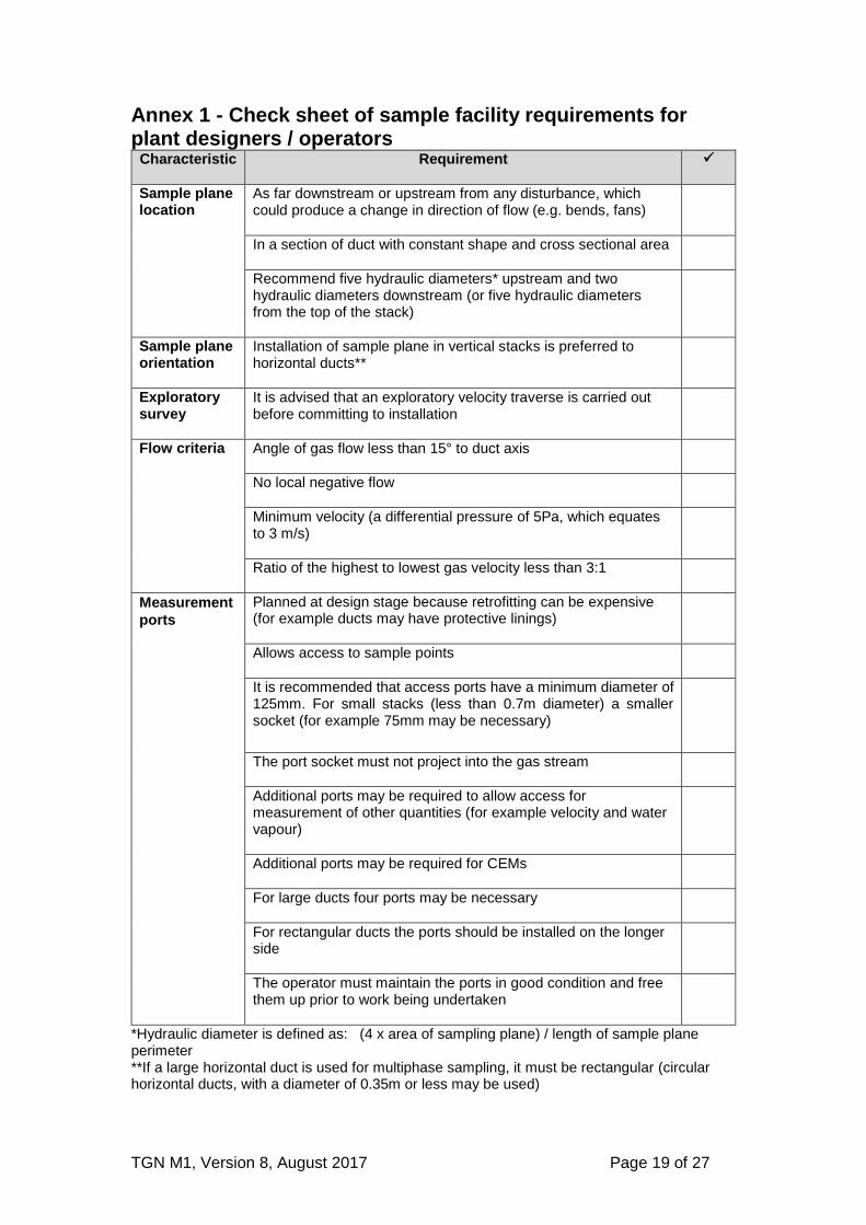
Annex 1 - Check sheet of sample facility requirements for plant designers / operators
Characteristic
Requirement
Sample plane location
As far downstream or upstream from any disturbance, which could produce a change in direction of flow (e.g. bends, fans)
In a section of duct with constant shape and cross sectional area
Recommend five hydraulic diameters* upstream and two hydraulic diameters downstream (or five hydraulic diameters from the top of the stack)
Sample plane orientation
Installation of sample plane in vertical stacks is preferred to horizontal ducts**
Exploratory survey
It is advised that an exploratory velocity traverse is carried out before committing to installation
Flow criteria Angle of gas flow less than 15° to duct axis
No local negative flow
Minimum velocity (a differential pressure of 5Pa, which equates to 3 m/s)
Ratio of the highest to lowest gas velocity less than 3:1
Measurement
ports
Planned at design stage because retrofitting can be expensive (for example ducts may have protective linings)
Allows access to sample points
It is recommended that access ports have a minimum diameter of 125mm. For small stacks (less than 0.7m diameter) a smaller socket (for example 75mm may be necessary)
The port socket must not project into the gas stream
Additional ports may be required to allow access for measurement of other quantities (for example velocity and water vapour)
Additional ports may be required for CEMs
For large ducts four ports may be necessary
For rectangular ducts the ports should be installed on the longer side
The operator must maintain the ports in good condition and free them up prior to work being undertaken
*Hydraulic diameter is defined as: (4 x area of sampling plane) / length of sample plane perimeter **If a large horizontal duct is used for multiphase sampling, it must be rectangular (circular horizontal ducts, with a diameter of 0.35m or less may be used)
TGN M1, Version 8, August 2017 Page 20 of 27
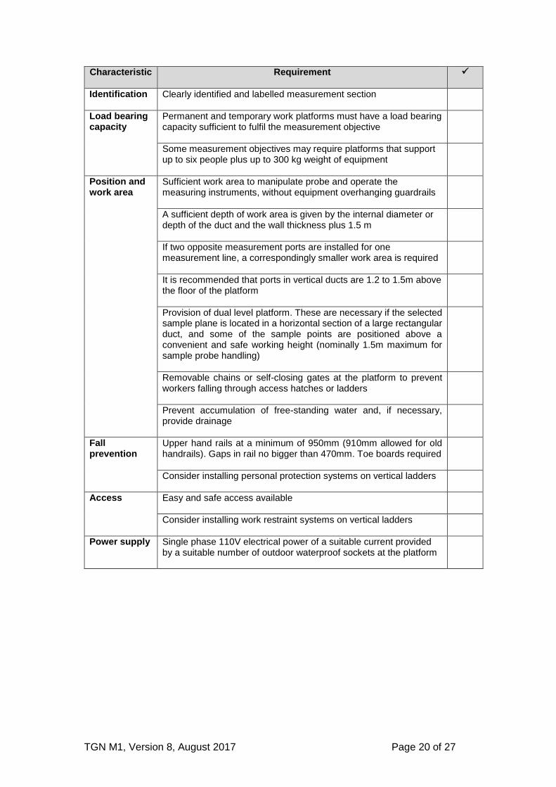
Characteristic
Requirement
Identification Clearly identified and labelled measurement section
Load bearing capacity
Permanent and temporary work platforms must have a load bearing capacity sufficient to fulfil the measurement objective
Some measurement objectives may require platforms that support up to six people plus up to 300 kg weight of equipment
Position and work area
Sufficient work area to manipulate probe and operate the measuring instruments, without equipment overhanging guardrails
A sufficient depth of work area is given by the internal diameter or depth of the duct and the wall thickness plus 1.5 m
If two opposite measurement ports are installed for one measurement line, a correspondingly smaller work area is required
It is recommended that ports in vertical ducts are 1.2 to 1.5m above the floor of the platform
Provision of dual level platform. These are necessary if the selected sample plane is located in a horizontal section of a large rectangular duct, and some of the sample points are positioned above a convenient and safe working height (nominally 1.5m maximum for sample probe handling)
Removable chains or self-closing gates at the platform to prevent workers falling through access hatches or ladders
Prevent accumulation of free-standing water and, if necessary, provide drainage
Fall prevention
Upper hand rails at a minimum of 950mm (910mm allowed for old handrails). Gaps in rail no bigger than 470mm. Toe boards required
Consider installing personal protection systems on vertical ladders
Access Easy and safe access available
Consider installing work restraint systems on vertical ladders
Power supply Single phase 110V electrical power of a suitable current provided by a suitable number of outdoor waterproof sockets at the platform
TGN M1, Version 8, August 2017 Page 21 of 27
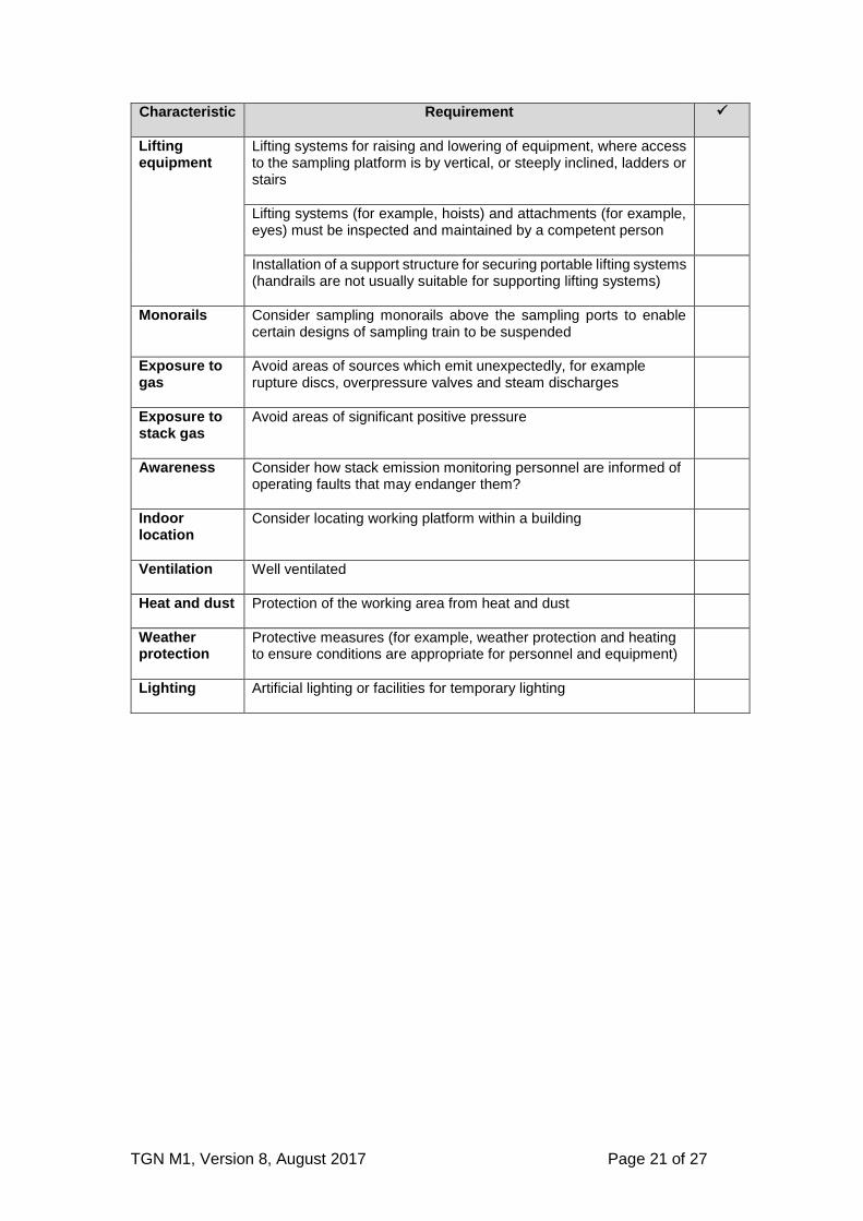
Characteristic
Requirement
Lifting equipment
Lifting systems for raising and lowering of equipment, where access to the sampling platform is by vertical, or steeply inclined, ladders or stairs
Lifting systems (for example, hoists) and attachments (for example, eyes) must be inspected and maintained by a competent person
Installation of a support structure for securing portable lifting systems (handrails are not usually suitable for supporting lifting systems)
Monorails Consider sampling monorails above the sampling ports to enable certain designs of sampling train to be suspended
Exposure to gas
Avoid areas of sources which emit unexpectedly, for example rupture discs, overpressure valves and steam discharges
Exposure to stack gas
Avoid areas of significant positive pressure
Awareness Consider how stack emission monitoring personnel are informed of operating faults that may endanger them?
Indoor location
Consider locating working platform within a building
Ventilation Well ventilated
Heat and dust Protection of the working area from heat and dust
Weather protection
Protective measures (for example, weather protection and heating to ensure conditions are appropriate for personnel and equipment)
Lighting Artificial lighting or facilities for temporary lighting
TGN M1, Version 8, August 2017 Page 22 of 27
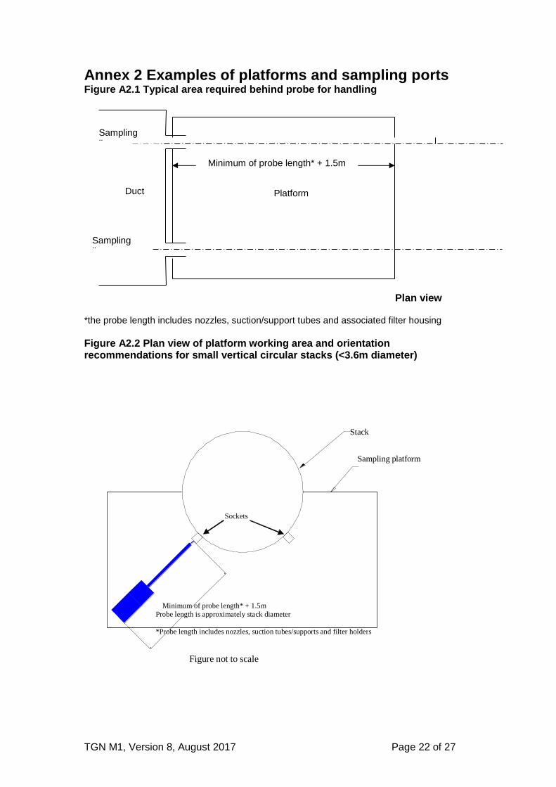
Annex 2 Examples of platforms and sampling ports Figure A2.1 Typical area required behind probe for handling
*the probe length includes nozzles, suction/support tubes and associated filter housing
Figure A2.2 Plan view of platform working area and orientation recommendations for small vertical circular stacks (<3.6m diameter)
Sampling platform
Stack
Minimum of probe length* + 1.5m
Probe length is approximately stack diameter
*Probe length includes nozzles, suction tubes/supports and filter holders
Figure not to scale
Sockets
Duct
Sampling line
Platform area
Plan view
Sampling line
Minimum of probe length* + 1.5m
TGN M1, Version 8, August 2017 Page 23 of 27
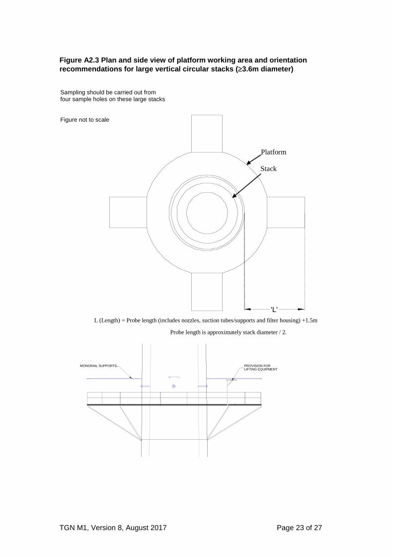
Figure A2.3 Plan and side view of platform working area and orientation
recommendations for large vertical circular stacks (3.6m diameter)
Platform
Stack
'L'
L (Length) = Probe length (includes nozzles, suction tubes/supports and filter housing) +1.5m
Probe length is approximately stack diameter / 2.
PROVISION FORLIFTING EQUIPMENT
MONORAIL SUPPORTS
Sampling should be carried out from four sample holes on these large stacks Figure not to scale
TGN M1, Version 8, August 2017 Page 24 of 27
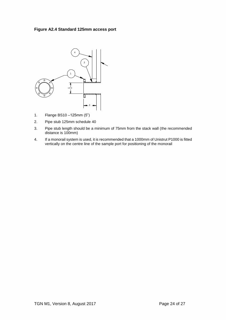
Figure A2.4 Standard 125mm access port
1. Flange BS10 –125mm (5”)
2. Pipe stub 125mm schedule 40
3. Pipe stub length should be a minimum of 75mm from the stack wall (the recommended distance is 100mm)
4. If a monorail system is used, it is recommended that a 1000mm of Unistrut P1000 is fitted vertically on the centre line of the sample port for positioning of the monorail
STACK WALL
1
2
4
3
129.30
TGN M1, Version 8, August 2017 Page 25 of 27
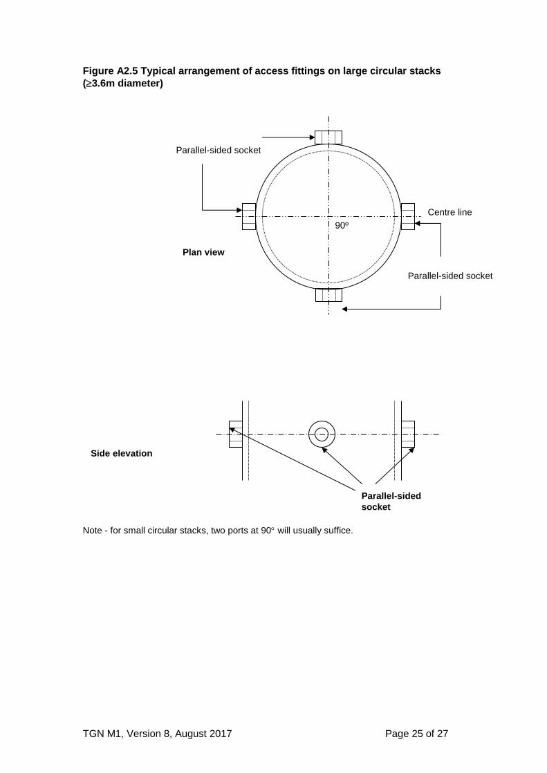
Figure A2.5 Typical arrangement of access fittings on large circular stacks
(3.6m diameter)
Note - for small circular stacks, two ports at 90 will usually suffice.
90º
Centre line
Parallel-sided socket
Parallel-sided socket
Plan view
Parallel-sided
socket
Side elevation
TGN M1, Version 8, August 2017 Page 26 of 27
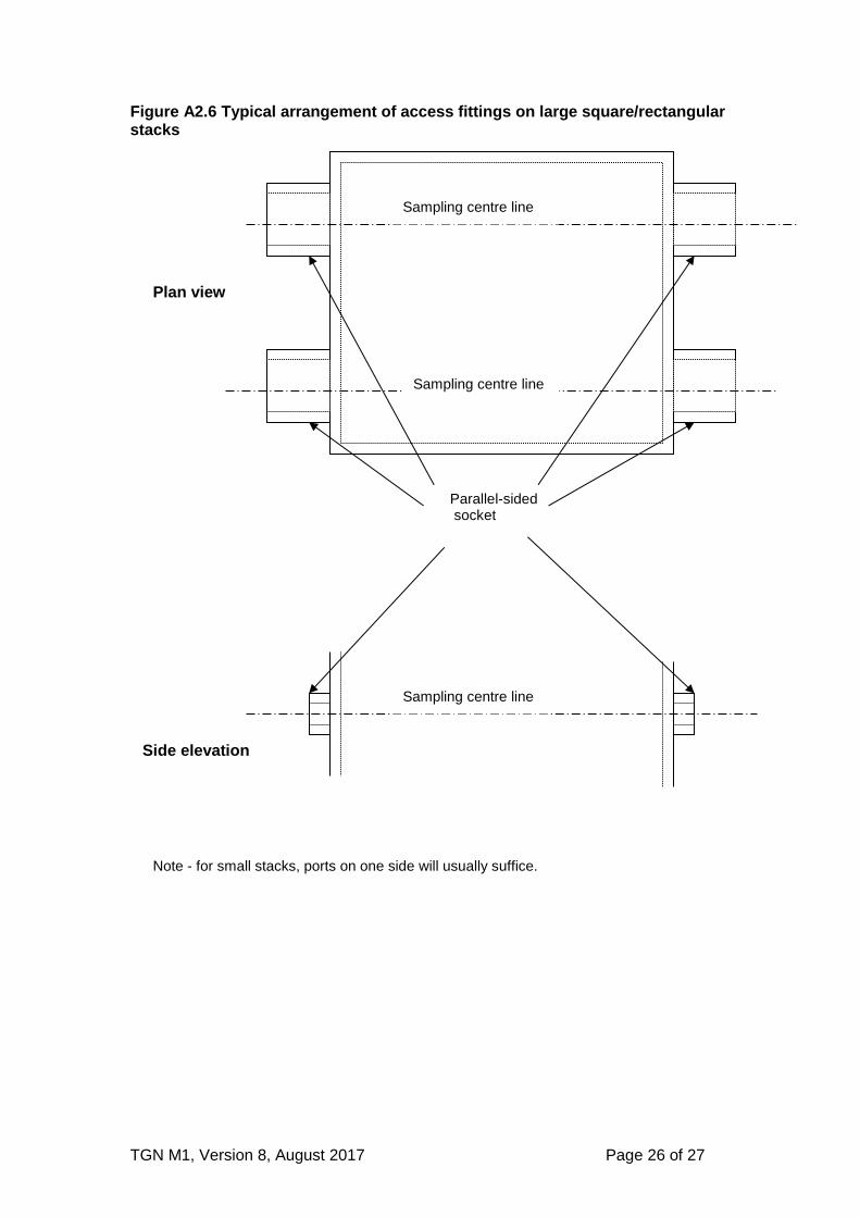
Figure A2.6 Typical arrangement of access fittings on large square/rectangular stacks
Sampling centre line
Sampling centre line
Parallel-sided socket
Plan view
Side elevation
Sampling centre line
Note - for small stacks, ports on one side will usually suffice.
TGN M1, Version 8, August 2017 Page 27 of 27
References
1. MCERTS, Manual stack-emission monitoring: performance standard for organisations. Environment Agency. Available from www.mcerts.net.
2. MCERTS, Manual-stack emission monitoring: personnel competency
standard. Environment Agency. Available from www.mcerts.net.
3. BS EN 15259:2007 Requirements for measurement sections and sites and for the measurement objective, plan and report.
4. Environment Agency Method Implementation Document for EN 15259.
Available from www.mcerts.net.net
5. BS EN 14181:2004. Stationary source emissions – Quality assurance of automated measuring systems.
6. Technical Guidance Note M20 - Quality assurance of continuous emissions
monitoring systems - application of BS EN 14181 and BS EN 13284-1. Environment Agency. Available from www.mcerts.net.
7. The Working at Heights Regulations (WAHR) 2005. Health and Safety
Executive. Available from www.opsi.gov.uk/si/si2005/20050735.htm
8. Health and Safety at Work Act 1974. Health and Safety Executive. Available from http://www.hse.gov.uk/legislation/hswa.htm
LIT 4736