technical description template - helicentrohelicentro.com.br/md500series-descricao-tecnica.pdfthis...
TRANSCRIPT

TECHNICAL DESCRIPTION
00
Marketing and Sales 4555 E. McDowell Road
Mesa, Arizona 85215-9734
Comments and/or questions may be directed to: Sales: (480) 346-6344 Fax: (480) 346-6339
E-mail: [email protected]
Revised January 2011 © 2011 MD Helicopters, Inc. All rights reserved.
This Technical Description is not subject to a revision service. It is the manufacturer’s practice to continuously improve its products and therefore the right is reserved to make changes without notice in the design or manufacture of the MD 500 Series helicopters which may be considered necessary.
MD 530F
MD 500E
MD 520N


TABLE OF CONTENTS
TABLE OF CONTENTS page 1.0 MD 500E® FEATURES AND BENEFITS………………………………..………………………... 1
1.1 Dimensions………………………..…............................................................................... 2 2.0 MD 500E® STANDARD EQUIPMENT…………………………………………………………….… 3-5 3.0 MD 500E® PERFORMANCE SPECIFICATIONS……………………………………………......... 6-27
3.1 Performance Specifications (C20B Engine)………………………..….............................. 6 3.2 Performance Specifications (C20R Engine)………………………..….............................. 7 3.3 Hover-In-Ground-Effect (C20B Engine)…………………………………..………............... 8 3.4 Hover-Out-of-Ground-Effect (C20B Engine)………………..…………………………........ 9 3.5 Takeoff Gross Weight Worksheet (C20B Engine)……………….…………….................. 10 3.6 Payload vs. Range (5000’, ISA) (C20B Engine)…………..……………………………….. 11 3.7 Speed for Best Range (C20B Engine)…………..………………………………………….. 12 3.8 Speed for Best Endurance (C20B Engine)…………..…………………………………….. 13 3.9 Fuel Flow, Sea Level, ISA (15ºC) (C20B Engine)…………..…………………………….. 14 3.10 Fuel Flow, Sea Level, ISA + 20ºC (35ºC) (C20B Engine)…………..……………………. 15 3.11 Fuel Flow, 4000 feet, ISA (7ºC) (C20B Engine)…………..……………………………….. 16 3.12 Fuel Flow, 4000 feet, ISA + 20ºC (27ºC) (C20B Engine)…………..…………………….. 17 3.13 Hover-In-Ground-Effect (C20R Engine)…………..………………………………………… 18 3.14 Hover-Out-of-Ground-Effect (C20R Engine)…………..…………………………………… 19 3.15 Takeoff Gross Weight Worksheet (C20R Engine)…………..…………………………….. 20 3.16 Payload vs. Range (5000’, ISA) (C20R Engine)…………..……………………………….. 21 3.17 Speed for Best Range (C20R Engine)…………………………………………………….... 22 3.18 Speed for Best Endurance (C20R Engine)…………..…………………………………..... 23 3.19 Fuel Flow, Sea Level, ISA (15ºC) (C20R Engine)…………..……………..………………. 24 3.20 Fuel Flow, Sea Level, ISA + 20ºC (35ºC) (C20R Engine)………….…………………….. 25 3.21 Fuel Flow, 4000 feet, ISA (7ºC) (C20R Engine)…………..……………………………….. 26 3.22 Fuel Flow, 4000 feet, ISA + 20ºC (27ºC) (C20R Engine)…………..…………………….. 27 0
4.0 MD 500E® DIRECT OPERATING COST ESTIMATES…………..……………………………..... 28 4.1 MD 500E® Direct Operating Cost Worksheet……………………….....………..….......... 29
5.0 MD 500E® COMPONENT MAINTENANCE SCHEDULE………………………………………… 30
6.0 MD 530F® FEATURES AND BENEFITS……………..…………………………………………….. 31
6.1 Dimensions…………………….……………………………..….......................................... 32 7.0 MD 530F® STANDARD EQUIPMENT…………………………..………………………………….. 33-35
8.0 MD 530F® PERFORMANCE SPECIFICATIONS………………………………………………….. 36-46
8.1 Hover-In-Ground Effect……….……………………………..….......................................... 37 8.2 Hover-Out-of-Ground Effect………………………..……………….................................... 38 8.3 Takeoff Gross Weight Worksheet…………………………………..………........................ 39 8.4 Payload vs. Range (5000’, ISA)….………………………………..…................................. 40 8.5 Speed for Best Range…………………….…………………...............................………… 41 8.6 Speed for Best Endurance………………………………..………...................................... 42 8.7 Fuel Flow, Sea Level, ISA (15˚C)….………………………………..….............................. 43 8.8 Fuel Flow, Sea Level, ISA + 20˚C (35˚C).…………..…………………............................. 44 8.9 Fuel Flow, 4,000 feet, ISA (7˚C)…………..…………………............................................ 45 8.10 Fuel Flow, 4,000 feet, ISA + 20˚C (27˚C)…………………………………..………............ 46


TABLE OF CONTENTS
page 9.0 0MD 530F® DIRECT OPERATING COST ESTIMATES…………………………………………….
47
9.1 MD 530F® Direct Operating Cost Worksheet…………………..……………................. 48
10.0 MD 530F® COMPONENT MAINTENANCE SCHEDULE.………………………………………... 49 11.0 MD 520N® SYSTEM DESCRIPTION……………………………………………………………..…. 50-60
11.1 MD 520N® Design Description…………..…................................................................... 51 11.1.1--- MD 520N® Outside Dimensions………..…………………...........................….. 51 11.1.2--- MD 520N® Inboard Profile and Features…………………………..……............ 53
11.2 MD 520N® On Patrol……….……………………………..…............................................ 54 11.2.1---Maintenance made easy……………….…………..............................……….…. 55 11.2.2---Interchangeability…………..……………………..……........................................ 56
11.3 NOTAR® Anti-Torque System…….………………………………..…............................... 57 11.3.1---Description of the NOTAR® System……..….……............................................. 57 11.3.2---NOTAR® System Components…………..…………………................................ 57 11.3.3---Reduced Aircraft Vibration…………………..……………..………....................... 58 11.3.4---Low External Noise……..…………………..............................……………..….... 59 11.3.5---Inherent Safety…………..……………..….......................................................... 60 11.3.6---Improved Handling…………………………………..……..................................... 60
12.0 MD 520N® STANDARD EQUIPMENT…………………………………………………………….... 61-63 13.0 MD 520N® PERFORMANCE SPECIFICATIONS………………………………………………….. 64-74
13.1 Hover-In-Ground Effect……….……………………………..….......................................... 65 13.2 Hover-Out-of-Ground Effect………………………..……………….................................... 66 13.3 Takeoff Gross Weight Worksheet…………………………………..………........................ 67 13.4 Payload vs. Range (5000’, ISA)….………………………………..…................................. 68 13.5 Speed for Best Range…………………..…………………..................................………… 69 13.6 Speed for Best Endurance…………………………………..……….................................. 70 13.7 Fuel Flow, Sea Level, ISA (15˚C)….………………………………..….............................. 71 13.8 Fuel Flow, Sea Level, ISA + 20˚C (35˚C)…………..………………….............................. 72 13.9 Fuel Flow, 4,000 feet, ISA (7˚C)…………..…………………............................................ 73 13.10 Fuel Flow, 4,000 feet, ISA + 20˚C (27˚C)...…………………………………..………......... 74
14.0 MD 520N® DIRECT OPEARTING COST ESTIMATES......……………………………………….. 75
14.1 MD 520N Direct Operating Cost per Hour Worksheet………………............................... 76
15.0 COMPONENT MAINTENANCE SCHEDULE……………........................................................... 77
16.0 MD500 SERIES OPTIONAL EQUIPMENT…………………………………………………….……. 78-81
17.0 PRODUCT SUPPORT PLAN…………………………………………………………………….…… 82-84 18.0 TRAINING…………………………………………………………………………………………….…. 85-86


1
FEATURES AND BENEFITS
1.0 MD500E® Features and Benefits
The MD 500E® delivers the highest speed, payload and productivity in its class. Rear seat passengers have greater headroom and visibility than earlier Model 500s. Refinements provide first class front and rear seating with ample legroom. The T-shaped instrument panel provides space for a full complement of modern avionics.
With a five-bladed main rotor and the choice of a 420-shp Rolls-Royce 250-C20B or 450-shp Rolls-Royce 250-C20R turbine engine, the MD 500E® is the best performing helicopter in its class. The MD 500E® light turbine helicopter allows easy configuration conversions from a deluxe, five-place executive transport to a utility cargo carrier. Typical uses include urban and remote location transportation of key personnel, technicians and craftsmen; aerial survey, patrol and photography; agricultural and fire-fighting applications; air rescue operations; and numerous other tasks within the construction, petroleum and forestry industries.
Standard high-clearance skids permit operations in rough terrain, while other optional equipment, such as inflatable floats and litter kit increase the versatility of the MD 500E®.
Proven reliability of the de-rated turbine engine, fail-safe design and a worldwide network of factory-authorized service centers assure customer satisfaction.
STANDARD COCKPIT INTERIOR STANDARD CABIN INTERIOR

2
DIMENSIONS
1.1 Dimensions

3
STANDARD EQUIPMENT
2.0 MD 500E® Standard Equipment
Airframe Extended Landing Gear Rapid Door Removal Hinges (cockpit and cabin) Tinted Canopy Panels Tinted Door/window panel-left front Tinted Door/window panel-left rear Tinted Door/window panel-right front Tinted Door/window panel-right rear Rain Gutter Set Keyed Locks (4) Fuselage Hard Points Jacking Fittings Passenger Steps Anti-collision Lights (2) Landing Light, nose mounted Position Lights
Interior
LH Rotor Brake Heater Defogger System Crew Seats with 4-point Harness Restraint Passenger Seats with 3-point Harness Restraint Vinyl and Fabric Cushions Vinyl Interior Trim Panels Crew and Cabin Compartment Floor Carpet Map Case Fire Extinguisher First-Aid Kit Cabin 28-volt Utility Outlet Battery-Heavy Duty Marathon 17-ampere-hour Fresh Air Ventilation System Cockpit Utility Light Cabin Convenience Light Instrument Lighting Cabin Soundproofing Cargo Tie-Down Fittings
Rotor and Controls
Dual LH Command Flight Controls
4
STANDARD EQUIPMENT
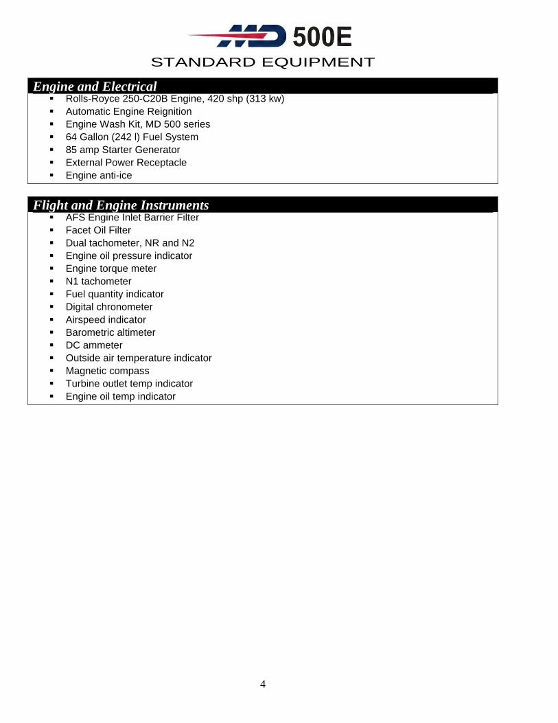
Engine and Electrical Rolls-Royce 250-C20B Engine, 420 shp (313 kw) Automatic Engine Reignition Engine Wash Kit, MD 500 series 64 Gallon (242 l) Fuel System 85 amp Starter Generator External Power Receptacle Engine anti-ice
Flight and Engine Instruments
AFS Engine Inlet Barrier Filter Facet Oil Filter Dual tachometer, NR and N2 Engine oil pressure indicator Engine torque meter N1 tachometer Fuel quantity indicator Digital chronometer Airspeed indicator Barometric altimeter DC ammeter Outside air temperature indicator Magnetic compass Turbine outlet temp indicator Engine oil temp indicator

5
STANDARD EQUIPMENT
Annuciator Panel Battery Overtemp Warning Light Engine Chip Detector Warning Light Engine Out Warning Light Fuel Filter Obstruction Warning Light Fuel Low Warning Light Generator Out Warning Light Low Rotor rpm Warning Light Main Transmission Chip Detector Warning Light Main Transmission Oil Pressure Warning Light Main Transmission Oil Temp Warning Light Tail Rotor Transmission Chip Detector Warning Light
Miscellaneous
Engine and Airframe Log Books Engine Maintenance Manual Battery Logbook Flight Manual Handbook of Maintenance Instructions Illustrated Parts Catalog Engine Exhaust Cover Engine Inlet Cover Pitot Tube Cover Fan Inlet Cover Main Rotor Blade Tie-Downs Ground Handling Wheels One color paint

PERFORMANCE SPECIFICATIONS
6
3.0 MD500E® PERFORMANCE SPECIFICATIONS
3.1 Performance Specifications (C20B Engine)
Performance With C20B Engine
Characteristics at Design Gross Weight Metric 1361 KG
Imperial 3000 lb.
Maximum Cruise Speed Sea level 1524 m (5,000 ft)
249 km/hr 246 km/hr
135 kt (155 mph) 133 kt (153 mph)
Speed for Best Range 1524 m (5,000 ft) 222 km/hr 120 kt (138 mph) Maximum Permitted Speed VNE at sea level 282 km/hr 152 kt (175 mph) Maximum Range Sea level
1524 m (5,000 ft) 478 km 537 km
258 nm (297 mi) 290 nm (304 mi)
Maximum Endurance Sea level 2.8 hr 2.8 hr Maximum Rate of Climb:(TOP) Sea level, Standard
day ISA +20° C day
9.0 m/sec 9.0 m/sec
1,770 fpm 1,776 fpm
Maximum Operating Altitude Density Altitude 4877 m
16,000 ft
Service Ceiling ISA 4227 m 13,900 ft Maximum Hook Capacity 907 kg 2,000 lb Hovering Performance In-ground effect Out-of-ground effect:
Standard day ISA + 20° C day Standard day ISA + 20° C day
2591 m 1829 m 1829 m 945 m
8,500 ft 6,000 ft 6,800 ft 3,100 ft
WEIGHTS Characteristics Metric Imperial Maximum Gross Weight Normal category 1361 kg 3,000 lb External load operations 1610 kg 3,550 lb Empty Weight Standard configuration 672 kg 1,481 lb Useful Load Normal category 689 kg 1,519 lb External load operations 938 kg 2,069 lb Usable Fuel Capacity 242 L (64 gal 183 kg 403 lb POWER PLANT Characteristics Metric Imperial Rolls-Royce Model 250-C20B gas turbine
Rated power: 313 kw 420 shp
Derated for reliability and safety to Takeoff power Max continuous power
280 kw 261 kw
375 shp 350 shp

PERFORMANCE SPECIFICATIONS
7
3.2 Performance Specifications (C20R Engine)
Performance with C20R Engine
Characteristics at Design Gross Weight Metric 1361 KG
Imperial 3000 lb.
Maximum Cruise Speed Sea level 1524 m (5,000 ft)
249 km/hr 251 km/hr
135 kt (155 mph) 136 kt (156 mph)
Speed for Best Range 1524 m (5,000 ft) 222 km/hr 120 kt (138 mph)
Maximum Permitted Speed VNE at sea level 282 km/hr 152 kt (175 mph) Maximum Range Sea level
1524 m (5,000 ft) 472 km 532 km
255 nm (293 mi) 287 nm (297 mi)
Maximum Endurance Sea level 2.7 hr 2.7 hr Maximum Rate of Climb:(TOP) Sea level, Standard day
ISA +20° C day 9.0 m/sec 9.0 m/sec
1,770 fpm 1,776 fpm
Maximum Operating Altitude Density Altitude 4877 m 16,000 ft Service Ceiling ISA 5029 m 16,500 ft Maximum Hook Capacity 907 kg 2,000 lb Hovering Performance In-ground effect Out-of-ground effect:
Standard day ISA + 20° C day Standard day ISA + 20° C day
3444 m 2103 m 2652 m 1250 m
11,300 ft 6,900 ft 9,500 ft 4,100 ft
WEIGHTS Characteristics Metric Imperial Maximum Gross Weight Normal category
External load operations1361 kg 1610 kg
3,000 lb 3,550 lb
Empty Weight Standard configuration 686 kg 1,517 lb Useful Load Normal category
External load operations673 kg 922 kg
1,483 lb 2.033 lb
Usable Fuel Capacity 242 L (64 gal) 183 kg 403 lb POWER PLANT Characteristics Metric Imperial
Rolls-Royce Model 250-C20B gas turbine, Rated power
336 kw 450 shp
De-rated for reliability and safety to
Takeoff power: Max. continuous power
280 kw 261 kw
375 shp 350 shp

PERFORMANCE SPECIFICATIONS
8 <<<< ROLLS ROYCE 250-C20B >>>>
16000
14000
12000
10000
8000
6000
4000
2000
02200 2400 2600 2800 3000 3200 3400 3600
PRES
SUR
EA
LTIT
UD
E-F
EET
GROSS WEIGHT - POUNDS
THIS CHART BASED ON CABIN HEAT, ENGINE ANTI-ICE OFF, ELECTRICAL LOAD 10 AMPERE, APPLICABLE TOPARTICLE SEPARATOR (SCAVENGE OFF) OR STANDARD ENGINE AIR INLET
REDUCE WEIGHT:1. 55LB WITH SCAVENGE ON2. 40LB WITH MIST ELIMINATOR INSTALLED
INCREASE WEIGHT: 50LB WITH ABRASION STRIPS ON MAINROTOR BLADES ONLY
DECREASE WEIGHT: 50LB WITH ABRASION STRIPS ON TAILROTOR BLADES ONLY
INCREASE (OR DECREASE) WT. CAPABILITY LBS (ABOVE CRITICAL ALTITUDE) PER 10 AMP REDUCTION (OR INCREASE) IN ELECTRICAL LOAD
OAT oC -5 15 35WTD 1 2 3
- 15 o- 5
515
25
35
45
oC
ISA+20
ISA
NOT VERIFIED WHEN MAIN ROTORBLADES HAVING ABRASION STRIPSARE INSTALLED
REDUCE WEIGHT CAPABILITIES lbs AS FOLLOWS:(APPLICABLE TO ALL TEMPERATURES)
PRESSUREALT. FT.
CABINHEAT
ANTI-ICE
BOTH
SL TO 400080001200016000
22015211186
23215711789
469306227172
- 25 oC
oCO A T
F03-036-1
o
o
o
o
o
o
3.3 Hover-In-Ground-Effect (C20B Engine)

PERFORMANCE SPECIFICATIONS
9
3.4 Hover-Out-of-Ground-Effect (C20B Engine),

PERFORMANCE SPECIFICATIONS
10
3.5 Takeoff Gross Weight Worksheet (C20B Engine)
C20B Mission #1 Mission #2
Empty Weight 1,481 lb
(672 kg)
Pilot 170 lb
(77 kg)
Fuel 403 lb
(183 kg)
Payload 946 lb
(428 kg)
Takeoff GW 3,000 lb
(1361 kg)

PERFORMANCE SPECIFICATIONS
11
3.6 Payload vs Range (5000’, ISA) (C20B Engine)
PERFORMANCE SPECIFICATIONS
12
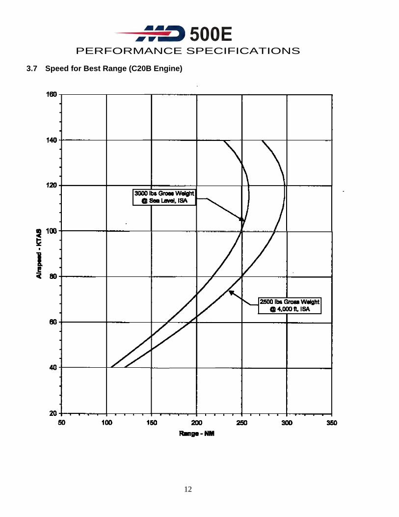
3.7 Speed for Best Range (C20B Engine)

PERFORMANCE SPECIFICATIONS
13
3.8 Speed for Best Endurance (C20B Engine)

PERFORMANCE SPECIFICATIONS
14
3.9 Fuel Flow, Sea Level, ISA (15°C) (C20B Engine)
Note: Use for Estimates Only. Not FAA Approved. Based on clean aircraft, level flight
performance, minimum specification engine, particle separator and 10 ampere electrical load.

PERFORMANCE SPECIFICATIONS
15
3.10 Fuel Flow, Sea Level, ISA +20°C (35°C) (C20B Engine)
Note: Use for Estimates Only. Not FAA Approved. Based on clean aircraft, level flight
performance, minimum specification engine, particle separator and 10 ampere electrical load.

PERFORMANCE SPECIFICATIONS
16
3.11 Fuel Flow, 4,000 feet, ISA (7°C) (C20B Engine)
Note: Use for Estimates Only. Not FAA Approved. Based on clean aircraft, level flight
performance, minimum specification engine, particle separator and 10 ampere electrical load.

PERFORMANCE SPECIFICATIONS
17
3.12 Fuel Flow, 4,000 feet, ISA +20°C (27°C) (C20B Engine)
Note: Use for Estimates Only. Not FAA Approved. Based on clean aircraft, level flight
performance, minimum specification engine, particle separator and 10 ampere electrical load.

PERFORMANCE SPECIFICATIONS
18
3.13 Hover-In-Ground-Effect (C20R Engine)

PERFORMANCE SPECIFICATIONS
19
3.14 Hover-Out of-Ground-Effect (C20R Engine)

PERFORMANCE SPECIFICATIONS
20
3.15 Takeoff Gross Weight Worksheet (C20R Engine)
C20R Mission #1 Mission #2
Empty Weight 1,517 lb (688 kg)
Pilot 170 lb (77 kg)
Fuel 403 lb (183 kg)
Payload 910 lb (413 kg)
Takeoff GW 3,000 lb (1361 kg)

PERFORMANCE SPECIFICATIONS
21
3.16 Payload vs Range (5000’, ISA) (C20R Engine)

PERFORMANCE SPECIFICATIONS
22
3.17 Speed for Best Range (C20R Engine)

PERFORMANCE SPECIFICATIONS
23
3.18 Speed for Best Endurance (C20R Engine)

PERFORMANCE SPECIFICATIONS
24
3.19 Fuel Flow, Sea Level, ISA (15°C) (C20R Engine)
Note: Use for Estimates Only. Not FAA Approved. Based on clean aircraft, level flight
performance, minimum specification engine, particle separator and 10 ampere electrical load

PERFORMANCE SPECIFICATIONS
25
3.20 Fuel Flow, Sea Level, ISA +20°C (35°C) (C20R Engine)
Note: Use for Estimates Only. Not FAA Approved. Based on clean aircraft, level flight
performance, minimum specification engine, particle separator and 10 ampere electrical load.

PERFORMANCE SPECIFICATIONS
26
3.21 Fuel Flow, 4,000 feet, ISA (7°C) (C20R Engine)
Note: Use for Estimates Only. Not FAA Approved. Based on clean aircraft, level flight
performance, minimum specification engine, particle separator and 10 ampere electrical load.

PERFORMANCE SPECIFICATIONS
27
3.22 Fuel Flow, 4,000 feet, ISA +20°C (27°C) (C20R Engine)
Note: Use for Estimates Only. Not FAA Approved. Based on clean aircraft, level flight
performance, minimum specification engine, particle separator and 10 ampere electrical load.

DIRECT OPERATING COST ESTIMATES
28
4.0 MD 500E® Estimated Direct Operating Cost Per Hour (Based upon year 2010 US$)
C20B Engine
C20R+ Engine
Fuel and Lubricants 1: Fuel @ $3.93* gallon @ approx. 27 gallons per hour. Lubricants @ 3% of fuel Total Fuel ..................................................................................
$ 106.11 $ 3.18
$ 109.29
$ 113.97 $ 3.42
$ 117.39
Airframe Maintenance and Spares2:
Maintenance labor costs: Scheduled (.15 Manhours/Flight Hours) @ $75.00/Hour* Unscheduled (.26 Manhours/Flight Hours) @ $75.00/Hour* Spares Cost: Scheduled (Inspection) Parts: Used during periodic inspection i.e. filters, seals, o-rings, etc.....................................On-Condition/Unscheduled Part................................................Reserves: Component Overhaul (TBO) ....................................Reserves: Limited-Life Parts ................................................... Total Airframe Cost ...................................................................
$ 11.25 $ 19.50
$ 30.75
$ 5.78 $ 21.12 $ 45.52 $ 42.72
$ 115.14
$ 11.25 $ 19.50
$ 30.75
$ 5.78 $ 20.11 $ 45.52 $ 42.72
$ 115.14
Engine3:
Scheduled maintenance labor and parts..........................Reserve for engine overhaul, spares and accessories.......................................................................
Total Engine ..............................................................
$ 3.00
$ 70.19 $ 73.69
$ 3.00
$73.20 $ 75.20
Total Direct Operating Cost4 ........................................
$ 328.87
$ 338.48
1 Fuel cost and labor rate* is based on U.S. Average Average cost while operating under the following conditions: Gross Weight: 10% less than maximum certified Speed: Maximum Range Speed, 117 KIAS Altitude: 1,000 feet on a standard day 2 Overhaul costs are based on participation in factory exchange program 3 Engine fleet maintenance costs provided by Rolls-Royce Engine Company 4 Indirect costs such as insurance, hangar, salary, etc., are excluded
Cost figures shown are extrapolated from a broad database and are intended for example purposes only. Actual costs will vary, depending on local operating condition, pricing and supplier practices. We encourage you top compare these figures with other manufacturers, using the same unit costs for fuel, labor, etc.

DIRECT OPERATING COST ESTIMATES
29
4.1 MD 500E® Direct Operating Cost Worksheet Fuel and Lubricants
Fuel and Lubricants
Fuel @ $ per gallon @ approx. gallons per hour……………………………………… $_________
Lubricants @ ______ % of fuel ……………………………………………………….... $_________
Total Fuel and Lubricants Cost……………………………………………………….. $_________(A) Airframe Maintenance and Spares
Scheduled maintenance labor rate @ $ _______ per hour
(Maintenance man-hour/flight hour=$ _______ )……………………………....
$_________ Unscheduled maintenance labor rate @ $ _______ per hour
(Maintenance man-hour/flight hour=$ _______ ) ………………….…………..
$_________
Scheduled (Inspection) Parts …………………………………………………………… $_________
On-Condition/Unscheduled Part ……………………………………………………….. $_________
Reserves: Component Overhaul (TBO) ……………………………………………….. $_________
Reserves: Limited-Life Parts ……………………………………………………………. $_________
Total Airframe Maintenance and Spares Cost……………………………………... $_________(B) Engine
Scheduled maintenance labor rate @ $ _______ per hour
(Maintenance man-hour/flight hour=$ _______ ) ………………………….....
$_________ Unscheduled maintenance labor rate @ $ _______ per hour
(Maintenance man-hour/flight hour=$ _______ ) __ …………………………..
$_________
Reserves for engine overhaul and spares …………………………………………...... $_________
Total Engine Cost ………………………………………………………………………. $_________(C)
TOTAL DIRECT OPERATING COST (A+B+C) …………………………………. $_________(D)
FIXED OPERATING COST FIXED OPERATING COST Depreciation
Hull insurance …………………………………………………………………………….. $_________
Liability insurance ………………………………………………………………………… $_________
Pilot salary ………………………………………………………………………………… $_________
Hangar rental …………………………………………………………..…………………. $_________
Total Annual Fixed Operating Cost …………………………………….…………… $_________(E) Total Hours ( _____________ ) flown annually (F) ………………………….………. $_________(F) TOTAL FIXED OPERATING COST PER HOUR (E+F) ………………………….…. $_________(G) Total Direct Operating Cost Per Hour (from above) ………………….…..……….. $_________(D) TOTAL HOURLY FIXED OPERATING COST (D+G)………………………………... $_________

COMPONENT MAINTENANCE SCHEDULE
30
5.0 Component Maintenance Schedule
Limited-Life Parts
Component Finite Time (hr)
Main Rotor Blade 3,530
Blade Pin 7,600
Main Rotor Hub 8,900
Pitch Housing/MR 9,100
Retention Strap/MR 2.770
Bolt-Lead Lag/Mr 6,120
Lead Lag Link/MR 11,080
Drive Shaft 5,020
Mast 10,450
Transmission Coupling 4,300
T/R Drive Shaft 13,900
T/R Transmission Input Shaft 12,000
T/R Transmission Output Shaft 7,290
T/R Blade 5,140
T/R Hub 3,450
T/R Retention Strap 5,100
Tail Boom Bolts 21,950
Tail Boom 10,300
Vertical Stabilizer 12,700
Horizontal Stabilizer 7,700
Idler Bellcrank 6,500
Overhaul Systems
Component Finite Time (hr)
Transmission/MR 5,000
M/R Swashplate 2,770
M/R Hub 2,770
Overrunning Clutch 1,800
T/R Transmission 4,800
Starter, Generator 1,200
Blower Bearings 1,200
Blower Belt 1,200

FEATURES AND BENEFITS
31
6.0 MD 530F® Features and Benefits
The MD 530F® is engineered to meet your requirements for hot-day, high-altitude operation. Equipped with the 650 shp Rolls-Royce 250-C30 engine, the MD 530F® operates more effectively in hot, high environments than other helicopters in its class. It offers the performance you need...at a lower cost of ownership. In a typical working configuration, at a design gross weight of 3,100 lb (1406 kg) and a useful load of over 1,509 lb (684 kg), it can hover out-of-ground effect at 11,600 ft (3536 m) ISA + 20°C. Cruise speed follows the tradition of the MD 500E®, making it one of the fastest helicopters in its class. An optional cargo hook rated for 2,000 lb (907 kg) provides outstanding external load capability. Internal loading is made easy by the flat aft cargo compartment floor of the helicopter. The high altitude lift capability of the MD 530F® is achieved by main-rotor blades six inches longer than the MD 500E®. The tailboom is extended eight inches and the tail rotor blades have been lengthened to provide increased thrust and directional control at high altitudes. The MD 530F® features the same streamlined, extended nose and interior design as the MD 500E®, making it the most versatile MD helicopter. The T-shaped instrument panel provides space for a full complement of avionics. Rear seat passengers have increased headroom and visibility. The MD 530F® light turbine helicopter allows easy conversion to a utility cargo carrier. The aft compartment is roomy enough to carry two 55-gallon drums on a flat floor. Outsized, bulky loads can be carried externally by the cargo hook, which is rated at 2,000 lb (907 kg). Standard high-clearance skids permit operation in rough terrain, while other optional equipment, such as inflatable floats and litter kit increase the versatility of the MD 530F®. Proven reliability, fail-safe design and the worldwide network of factory-authorized service centers assure customer satisfaction.
STANDARD COCKPIT INTERIOR STANDARD CABIN INTERIOR

DIMENSIONS
32
6.1 Dimensions
NOTES 1. Helicopter on ground with full fuel. Typical attitude of cargo deck 5.3 degrees nose up. 2. Height-above-ground dimensions vary with installed equipment, center of gravity and terrain features. 3. If standard landing gear is installed, all vertical dimensions will be 0.3 m (1.0 ft) less.

STANDARD EQUIPMENT
33
7.0 MD 530F® Standard Equipment *Required Options Included in Base Price as of 2008
Airframe Extended Landing Gear Rapid Door Removal Hinges (cockpit and cabin) Tinted Canopy Panels Tinted Door/window panel-left front Tinted Door/window panel-left rear Tinted Door/window panel-right front Tinted Door/window panel-right rear Rain Gutter Set Keyed Locks (4) Fuselage Hard Points Jacking Fittings Passenger Steps Anti-Collision Lights (2) Landing Light, nose mounted Position Lights
Interior LH Rotor Brake Heater Defogger System Crew Seats with 4-point Harness Restraint Passenger Seats with 3-point Harness Restraint Vinyl and Fabric Cushions Vinyl Interior Trim Panels Crew and Cabin Compartment Floor Carpet Map Case Fire Extinguisher First-Aid Kit Cabin 28-volt Utility Outlet Battery-Heavy Duty Marathon 17-ampere-hr Fresh Air Ventilation System Cockpit Utility Light Instrument Lighting Cabin Soundproofing Cargo Tie-Down Fittings Cabin Convenience Light
Rotors and Controls Dual LH Command Flight Controls

STANDARD EQUIPMENT
34
Engine and Electrical
Rolls-Royce 250-C30 Engine, 650 shp (485 kw) Automatic Engine Reignition Engine Wash Kit, MD 500 series 64 Gallon (242 L) Fuel System 85 amp Starter Generator 200 amp Starter Generator External Power Receptacle Engine Anti-Ice
Flight and Engine Instruments
AFS Engine Inlet Barrier Filter Facet Oil Filter Dual Tachometer, NR and N2 Engine Oil Pressure Indicator Engine Torque Meter Engine Oil Temp Indicator N1 Tachometer Fuel Quantity Indicator Digital Chronometer Airspeed Indicator Barometric Altimeter DC Ammeter Outside Air Temperature Indicator Magnetic Compass Turbine Outlet Temp Indicator

STANDARD EQUIPMENT
35
Annuciator Panel
Battery Overtemp Warning Light Engine Chip Detector Warning Light Engine Out Warning Light Fuel Filter Obstruction Warning Light Fuel Low Warning Light Generator Out Warning Light Low Rotor rpm Warning Light Main Transmission Chip Detector Warning Light Main Transmission Oil Pressure Warning Light Main Transmission Oil Temperature Warning Light Tail Rotor Transmission Chip Detector Warning Light
Miscellaneous
Ground handling wheels Engine and airframe log books Engine maintenance manual Battery logbook Flight manual Handbook of maintenance instructions Illustrated parts catalog Engine exhaust cover Engine inlet cover Pitot Tube Cover Main Rotor Blade Tie-Downs One color paint

PERFORMANCE SPECIFICATIONS
36
8.0 Performance Specifications Characteristics at Design Gross Weight
Metric 1406 kg
Imperial 3,100 lb
Maximum Cruise Speed Sea Level 1524 m (5,000 ft)
248 km/hr 249 km/hr
134 kt (154 mph) 135 kt (155 mph)
Speed for Best Range 1524 m (5,000 ft) 243 km/hr 118 kt (219 mph)
Maximum Permitted Speed
VNE at sea level 282 km/hr 152 kt (175 mph)
Maximum Range Sea Level 1524 m (5,000 ft)
2.2 hrs 430 km
2.2 hrs (237 m) 232 nm (267 m)
Maximum Endurance Sea Level 381 km 206 nm (237 m)
Maximum Rate of Climb Sea Level, Standard Day ISA +20° C Day
10.5 m/sec 105 m/sec
2069 fpm 2061 fpm
Maximum Operating Altitude
Density Altitude 6096 m 20,000 ft
Service Ceiling ISA 5700 m 18,700 ft
Maximum Hook Capacity
907 kg 2,000 lb
Hovering Performance (No wind) In-ground effect Standard Day
ISA +20° C Day 4877 m 4359 m
16,000 ft 14,300 ft
Out-of-ground effect Standard Day ISA +20° C Day
4389 m 3536 m
14,400 ft 11,600 ft
WEIGHTS Characteristics Metric Imperial Maximum Gross Weight Normal Capacity
External Load Operations 1406 kg 1701 kg
3,100 lb 3,750 lb
Empty Weight Standard Configuration 722 kg 1,591 lb
Useful Load Normal Capacity 684 kg 1,509 lb
External Load Operations
979 kg 2,159 lb
Usable Fuel Capacity 242 l (64 gal) 183 kg 403 lb
POWER PLANT Characteristics Metric Imperial Rolls-Royce 250-C30 gas turbine
Rated Power 485 kw 650 shp
Derated for reliability and safety to
Takeoff Power Max Continuous Power
317 kw 280 kw
425 shp 375 shp

PERFORMANCE SPECIFICATIONS
37
8.1 Hover-In-Ground-Effect

PERFORMANCE SPECIFICATIONS
38
8.2 Hover-Out of-Ground-Effect

PERFORMANCE SPECIFICATIONS
39
8.3 Takeoff Gross Weight Worksheet
Example Mission #1 Mission #2 Empty Weight 1,591 lb
(722 kg)
Pilot 170 lb (77 kg)
Fuel 403 lb (183 kg)
Payload 936 lb (424 kg)
Takeoff GW 3,100 lb (1406 kg)

PERFORMANCE SPECIFICATIONS
40
8.4 Payload vs Range (5000’, ISA)

PERFORMANCE SPECIFICATIONS
41
8.5 Speed for Best Range

PERFORMANCE SPECIFICATIONS
42
8.6 Speed for Best Endurance

PERFORMANCE SPECIFICATIONS
43
8.7 Fuel Flow, Sea Level, ISA (15°C)
Note: Use for Estimates Only. Not FAA Approved. Based on clean aircraft, level flight performance, minimum specification engine, particle separator and 10 ampere electrical load.

PERFORMANCE SPECIFICATIONS
44
8.8 Fuel Flow, Sea Level, ISA +20°C (35°C)
Note: Use for Estimates Only. Not FAA Approved. Based on clean aircraft, level flight performance, minimum specification
engine, particle separator and 10 ampere electrical load.

PERFORMANCE SPECIFICATIONS
45
8.9 Fuel Flow, 4,000 feet, ISA (7°C)
Note: Use for Estimates Only. Not FAA Approved. Based on clean aircraft, level flight performance, minimum specification
engine, particle separator and 10 ampere electrical load.

PERFORMANCE SPECIFICATIONS
46
8.10 Fuel Flow, 4,000 feet, ISA +20°C (27°C)
Note: Use for Estimates Only. Not FAA Approved. Based on clean aircraft, level flight performance, minimum specification engine, particle separator and 10 ampere electrical load.

DIRECT OPERATING COST ESTIMATES
47
9.0 MD 530F® Estimated Direct Operating Cost Per Hour (Based upon year 2010US)
C30 Engine
Fuel and Lubricants 1: Fuel @ $3.93* per gallon @ approx. 35 gallons per hour. ............................ Lubricants @ 3% of fuel ................................................................................ Total Fuel .....................................................................................................
$ 137.55 $ 4.13
$ 141.68
Airframe Maintenance and Spares2: Maintenance labor costs: Scheduled (.15 Manhours/Flight Hours) @ $75.00/Hour*............................. Unscheduled (.26 Manhours/Flight Hours) @ $75.00/Hour*......................... Spares Cost: Scheduled (Inspection) Parts: Used during periodic inspection i.e. filters, seals, o-rings, etc .......................................................................................... On-Condition/Unscheduled Part ................................................................... Reserves: Component Overhaul (TBO)........................................................ Reserves: Limited-Life Parts ........................................................................ Total Airframe Cost ......................................................................................
$ 11.25 $ 19.50
$ 30.75
$ 5.78 $ 21.12 $ 46.93 $ 48.92
$ 122.75
Engine3: Scheduled maintenance labor and parts............................................... Reserve for engine overhaul, spares and accessories ...........................................................................................
Total Engine ......................................................................................................
$ 3.00
$ 70.91 $ 73.91
Total Direct Operating Cost4 ...........................................................................
$ 369.09
1 Fuel cost and labor rate* is based on U.S. Average
Average cost while operating under the following conditions: Gross Weight: 10% less than maximum certified Speed: Maximum Range Speed, 124 KIAS Altitude: 1,000 feet on a standard day 2 Overhaul costs are based on participation in factory exchange program 3 Engine fleet maintenance costs provided by Rolls-Royce Engine Company 4 Indirect costs such as insurance, hangar, salary, etc., are excluded
Cost figures shown are extrapolated from a broad database and are intended for example purposes only. Actual costs will vary, depending on local operating condition, pricing and supplier practices. We encourage
you top compare these figures with other manufacturers, using the same unit costs for fuel, labor, etc.

DIRECT OPERATING COST ESTIMATES
48
9.1 MD 530F® Direct Operating Cost Worksheet
Fuel and Lubricants
Fuel @ $ per gallon @ approx. gallons per hour…………………………………….. $_________
Lubricants @ ______ % of fuel ………………………………………………………... $_________
Total Fuel and Lubricants Cost……………………………………………………… $_________(A) Airframe Maintenance and Spares
Scheduled maintenance labor rate @ $ _______ per hour
(Maintenance man-hour/flight hour=$ _______ )……………………………...
$_________ Unscheduled maintenance labor rate @ $ _______ per hour
(Maintenance man-hour/flight hour=$ _______ ) ………………….…………
$_________
Scheduled (Inspection) Parts …………………………………………………………. $_________
On-Condition/Unscheduled Part ……………………………………………………… $_________
Reserves: Component Overhaul (TBO) ……………………………………………… $_________
Reserves: Limited-Life Parts ………………………………………………………….. $_________
Total Airframe Maintenance and Spares Cost……………………………………. $_________(B) Engine
Scheduled maintenance labor rate @ $ _______ per hour
(Maintenance man-hour/flight hour=$ _______ ) …………………………..
$_________ Unscheduled maintenance labor rate @ $ _______ per hour
(Maintenance man-hour/flight hour=$ _______ ) __ …………………………
$_________
Reserves for engine overhaul and spares …………………………………………... $_________
Total Engine Cost …………………………………………………………………….. $_________(C)
TOTAL DIRECT OPERATING COST (A+B+C) ……………………………….. $_________(D)
FIXED OPERATING COST Depreciation
Hull insurance …………………………………………………………………………… $_________
Liability insurance ………………………………………………………………………. $_________
Pilot salary ………………………………………………………………………………. $_________
Hangar rental …………………………………………………………..……………….. $_________
Total Annual Fixed Operating Cost …………………………………….………….. $_________(E) Total Hours (______________ ) flown annually (F) ………………………….…….. $_________(F) TOTAL FIXED OPERATING COST PER HOUR (E+F) ………………………….… $_________(G) Total Direct Operating Cost Per Hour (from above) ………………….…..……… $_________(D) TOTAL HOURLY FIXED OPERATING COST (D+G)………………………………. $_________

COMPONENT MAINTENANCE SCHEDULE
49
10.0 Component Maintenance Schedule
Limited-Life Parts Component Finite Time (hr)
Main Rotor Blade 3,430
Blade Pin 7,600
Main Rotor Hub 8,900
Pitch Housing/MR 9,100
Retention Strap/MR 2,770
Bolt-Lead Lag/MR 6,120
Lead Lag Link/MR 11,080
Drive Shaft 3,675
Mast 10,450
Coupling 4,300
T/R Drive Shaft 14,610
T/R Transmission Input Shaft 3,365
T/R Transmission Output Shaft 7,290
T/R Blade 5,140
T/R Hub 3,450
T/R Retention Straps 5,100
Tail Boom 10,300
Vertical Stabilizer 3,388
Horizontal Stabilizer 7,700
Idler Bellcrank 6,500
Overhaul Systems Component Finite Time (hr)
Main Rotor Transmission 5,000
Main Rotor Swashplate 2,770
Main Rotor Hub 2,770
Overrunning Clutch 1,800
T/R Transmission 3,365
Starter Generator 1,200
Blower Bearings 1,200
Blower Belt 1,200

SYSTEM DESCRIPTION
50
11.0 MD 520N® SYSTEM DESCRIPTION
Airborne Law Enforcement Configuration
Fast: Vne of 175 miles per hour (250 kph) 154 miles per hour cruise speed (244 kph) Agile: Zero 0.5 g maneuvers NOTAR system precision attitude/directional control Powerful: Useful load at maximum gross weight 1,764 pounds (800 kg) internal 2,264 pounds (1027 kg) external HOGE at 6,000 ft (1829 m) @ISA HIGE at 11,200 ft (3414 m) @ISA ROC of 1,775 feet per minute (9.0 m/s) Versatile: 20,000 foot (6096 m) Maximum Operating Altitude Operating temperature range of -40˚C to +52˚C
15 degree slope landing
Safety: Elimination of tail rotor hazards Environment: Quiet operations – Flyover at 500 feet AGL = 72.5 dbA

SYSTEM DESCRIPTION
51
11.1 MD 520N® Design Description
The MD 520N® is a fast, agile, lightweight, turbine powered, all-purpose helicopter. Advanced technology has been used in the design and construction of the aircraft, resulting in excellent speed capabilities, high payload-to-empty-weight ratio, passenger/crew safety and handling and performance capabilities.
The MD 520N® has been designed to allow a wide variety of rapid configuration options. The aircraft may be converted rapidly from a personnel transport to a utility cargo configuration. Typical uses include:
Airborne Law Enforcement
Search and rescue
Surveillance and crowd control
Aerial survey, patrol and photographic missions
Forestry and fire fighting applications
The MDHI MD 520N® helicopter is a turbine powered, rotary-wing aircraft constructed primarily of aluminum alloy while the NOTAR® system components are primarily graphite composites. The main rotor is a fully articulated five-bladed system that provides excellent control and maneuverability characteristics. Power from the turboshaft engine is transmitted through the main drive shaft to the main rotor transmission. The main transmission drives an intermediate gearbox to the NOTAR® system fan. An over-running (one-way) clutch placed between the engine and main rotor transmission, permits freewheeling of the rotor system during autorotation.
The airframe structure is egg-shaped and provides very clean aerodynamic lines. A rigid, three-dimensional truss-type structure increases crew safety by means of its roll bar design and reduces the potential for airframe collapse into the crew and passenger compartments. The airframe structure is designed to be energy absorbing while maintaining rotor hub integrity.
11.1.1 MD 520N® Outside Dimensions
The fuselage is a semi-monoque structure that is divided into two main sections. The forward section is composed of the pilot/co-pilot compartment and directly aft, separated by a bulkhead, a cabin compartment. The pilot compartments equipped with seats for the pilot and either two passengers on the co-pilot. A canopy of transparent tinted acrylic panels provides excellent visibility.
An instrument panel is located forward of the seat structure along the aircraft centerline. The panel incorporates standard flight and engine instruments in addition to warning and caution lights. The panel also contains adequate space for avionics and flight instruments. An optional “slant panel” is available that increases the panel space available when extensive avionics suites are selected or when armament systems are installed.

SYSTEM DESCRIPTION
52

SYSTEM DESCRIPTION
53
11.1.2 MD 520N® Inboard Profile and Features
The crashworthy designed fuselage structure beneath the pilot/copilot floor contains space for the aircraft battery and provision for small cargo storage or installation of avionics equipment. Access to the compartments is through two floor panels. The cargo compartment is the center of the aircraft contains provisions for the installation of passenger seats, auxiliary fuel tanks or cargo/baggage. During cargo-carrying operations, the compartment floor serves as the cargo deck. The cargo floor is designed to accommodate a range of cargo requirements. The aft section includes the structure of the tailboom attachment, NOTAR® system fan and the engine compartment. Access to the engine compartment is provided through clamshell doors contoured to the shape of the fuselage. The lower section is divided by the center “keel beam” and provides housing for the two fuel cells containing a total of 64 U.S. gallons (242 l) of fuel.
Five-Blade Fully Articulated Main Rotor
Five-Place Seating Capacity
Simple Mechanical Controls
Crashworthy A-Frame Trusswith Integral Crew Seats
Static Mast Rotor Support
Outstanding Outward Visibility
425 shp Drive System
Flat Cargo FloorRolls-Royce 250-C20R 450 shp Turbine Engine
NOTAR ¨ Anti-Torque System

SYSTEM DESCRIPTION
54
11.2 MD 520N® On Patrol
Four doors are installed on the MD 520N® - two on each side. The two forward doors permit access to the forward compartment for pilot and copilot/passengers. The two aft doors allow entry to the passenger/cargo compartment. The design permits flight with doors removed without major speed restrictions. Transparent tinted windows are contained in the doors. A Rolls-Royce Model 250-C20RS gas turbine engine with a takeoff power rating of 450 shp powers the MD 520N®. Only 425 shp at l00 percent N2 rpm is used for takeoff; 375 maximum continuous shp provides power for all other flight modes. An overrunning clutch transmits power from the engine to the main drive shaft. The clutch has no external controls and disengages automatically during autorotation and engine shutdown. The main drive shaft connects to the main rotor transmission input shaft. The engine oil cooler blower is belt-driven off the main drive shaft and draws cooling air from the air inlet fairing to supply ambient air to the engine and transmission oil coolers and to the engine compartment. The main rotor transmission is mounted on the airframe structure above the passenger/cargo compartment. The transmission is lubricated by its own air-cooled oil lubrication system. The main rotor static mast is non- rotating and is rigidly mounted to the fuselage mast support structure. This static mast is used to separate the lift and torque loads of the rotor. Torque is transmitted independently to the rotor through an internal main rotor drive shaft. Lifting loads reacted by the static mast are prevented from being imposed through the drive shaft onto the main transmission, thus eliminating thrust loading of transmission parts. This accomplishes a design that reduces main transmission weight and reduces the probability of injury during a crash. The MD 520N® utilizes a five-blade, fully articulated main rotor assembly. The MDHI strap pack design provides restraint and allows all three degrees of rotor hub and rotor blade travel. The strap configuration, while secured firmly to the hub, allows the centrifugal load exerted by one blade to be countered by the force exerted by the opposite two blades.
SYSTEM DESCRIPTION
55
Thus, very light centrifugal loads are sensed by the hub. The “V” legs of the strap pack rotate as driving members to turn the blades and allow feathering, lead, lag and flapping of the blades. The main rotor blades are secured to the hub with quick-release lever type pins. Adjustable pedal controls are provided for rudder/thruster control. Adjustable friction devices are incorporated in the cyclic, collective and throttle controls. In addition, electrical cyclic trim actuators allow flight loads to be trimmed out. Control forces are low; hence, a hydraulic boost system is not required. The landing gear is a skid type attached to the fuselage at l2 points and is not retractable. Aerodynamic faring cover the struts. Nitrogen charged landing gear dampers act as springs and shock absorbers to cushion landings and provide ground resonance stability. Provisions for ground handling wheels are incorporated on the skid tubes.
11.2.1 Maintenance made easy
The MD 520N® incorporates proven engineering features that are unsurpassed for design simplicity, safety, reliability and ease of maintenance. There are no hydraulic boost systems, intermediate drive shaft bearings or grease fittings on any MD 500 series helicopters.
Blade Retention System: The mechanical simplicity of the main rotor system provides high reliability at low cost. Main rotor blades are retained by an exclusive strap pack system that accommodates main rotor blade flapping, lead-lag and feathering motions. Fewer parts result in higher reliability.
Main Rotor Transmission: The main transmission has four gears and two gear meshes. It is light but rugged for maximum reliability. The static mast design allows one mechanic to easily change the transmission without removing any other component on the rotor head.

SYSTEM DESCRIPTION
56
11.2.2 Interchangeability
Parts and assemblies listed below are interchangeable: 1. Main rotor blade (tracking of new blades may be required) 2. Main rotor hub assembly 3. Lead-lag damper 4. Main rotor drive shaft 5. Main rotor mast 6. Main transmission 7. Overrunning clutch 8. Main drive shaft 9. Engine assembly 10. Engine mount 11. Engine exhaust duct 12. NOTAR drive shaft 13. NOTAR gearbox 14. NOTAR blades 15. Control system components 16. Oil tank 17. Oil coolers (engine and main transmission) 18. Tail boom assembly 19. Vertical and Horizontal stabilizers 20. Fuel cells (left and right) 21. Electronic component assemblies and associated wire harnesses 22. Instruments 23. Landing gear assembly

SYSTEM DESCRIPTION
57
11.3 NOTAR® ANTI-TORQUE SYSTEM
Greater Safety: U.S. FAA, NTSB and U.S. Army Studies have shown that 21 percent of all crashes are due
to tailrotor strikes or loss of tail rotor effectiveness. NOTAR® systems eliminate these problems.
Reduced Noise
Designed and tested to be 50 percent quieter than any other helicopter. This results in detection distances that are far superior to other aircraft.
Reduced Pilot Workload
Using the Coanda Effect to provide tail boom lift and anti-torque, the system is more stable and easier to control. This effect reduces the sensitivity to wind direction on helicopter control, through providing an important tactical advantage during combat operations.
Low Pressure Air System
Since the NOTAR® system uses low-pressure air, it is not sensitive to holes made in the tailboom by fire from automatic weapons. Studies have shown the NOTAR® system is 60 percent less vulnerable to small arms fire than tail rotor systems on comparable helicopters.
11.3.1 DESCRIPTION OF THE NOTAR® SYSTEM
The NOTAR® system is an anti-torque system made up of an enclosed fan driven by the main rotor transmission, a circulation control tailboom, a direct jet thruster and a horizontal stabilizer with two vertical stabilators.

SYSTEM DESCRIPTION
58
11.3.2 NOTAR® System Components
The vertical stabilizers are connected to the pilot’s anti-torque (rudder) pedals. The left stabilizer moves through approximately 29 degrees of motion and provides sufficient control power for autorotation. It serves the additional purpose of unloading the thruster during forward flight to permit optimum cruise performance.
In hover flight, the circulation control tail boom provides the majority of the required main rotor anti-torque. This is accomplished by two slots along the tailboom that energize the downwash flow from the main rotor. The result is lift in a horizontal direction that replaces the push of a conventional tail rotor. The direct jet thruster provides the remaining anti-torque and maneuverability for yaw control and directional changes. In forward flight, the vertical stabilators, in conjunction with the direct-jet thruster, provide the required anti-torque and directional control.
11.3.3 REDUCED AIRCRAFT VIBRATION
The inherent stability of the standard MD 500 is further improved by the elimination of the exposed tail rotor assembly, which reduces overall helicopter vibrations and increases passenger comfort while reducing pilot fatigue.

SYSTEM DESCRIPTION
59
11.3.4 LOW EXTERNAL NOISE
The elimination of the high-tip-speed tail rotor assembly makes the MD 520N® the quietest turbine helicopter in the world. Recent comparative FAA tests conducted by MDHI indicate the MD 520N® is a minimum of 50 percent quieter than comparable helicopters. This lower noise signature makes the MD 520N® a “good neighbor’ when used in areas where noise is objectionable. Lower noise levels also increase survivability in hostile operational roles.

SYSTEM DESCRIPTION
60
80% Accidents Other than Tail
Rotor
6% All Accidents Avoidable 14% Accidents
Saved with NOTAR® System
11.3.5 INHERENT SAFETY
The NOTAR anti-torque system eliminates accidents and mishaps caused by the exposed tail rotor striking objects in flight, and significantly reduces ground incidents with people or equipment. Potential damage caused by foreign objects is also eliminated. Inherent design capabilities of the MD 520N® reduces the susceptibility to loss of tail rotor effectiveness and the problems associated with quartering tail winds. The power and stability of the MD 520N® in various wind conditions increase operational safety.
11.3.6 IMPROVED HANDLING
The excellent handling qualities of the MD 500 series have been further improved with the addition of the NOTAR® system. The MD 520N® has high control response provided by the fully articulated five-blade rotor system. Transient positive load factors of 2.8g’s and negative load factors of 0.0g’s are attainable with the MD 520N®. The NOTAR® system allows side and rearward flight speeds above 30 knots, low sensitivity to wind direction, 80 percent fewer pilot controls inputs and rapid turning rates.

STANDARD EQUIPMENT
61
12.0 MD 520N® Standard Equipment *Required Options Included in Base Price as of 2008
Airframe Extended Landing Gear Rapid Door Removal Hinges (cockpit and cabin) Tinted Canopy Panels Tinted Door/window panel-left front Tinted Door/window panel-left rear Tinted Door/window panel-right front Tinted Door/window panel-right rear Rain Gutter Set Keyed Locks (4) Fuselage Hard Points Jacking Fittings Passenger Steps Anti-Collision Lights (3) Landing light, nose mounted Position lights
Interior LH Rotor Brake Heater Defogger System Crew Seats with 4-point Harness Restraint Passenger Seats with 3-point Harness Restraint Vinyl and Fabric Cushions Vinyl Interior Trim Panels Crew and Cabin Compartment Floor Carpet Map Case Fire Extinguisher First-Aid Kit Cabin 28-volt Utility Outlet Battery-Heavy Duty Marathon 17-amp hour Fresh Air Ventilation System Cockpit Utility Light Cabin Convenience Light Instrument Lighting Cabin Soundproofing Cargo Tie-Down Fittings
Rotor and Controls Dual LH Command Flight Controls

STANDARD EQUIPMENT
62
Engine and Electrical Rolls-Royce 250-C20R Engine, 450 shp (336 kw) Automatic engine reignition Engine wash kit, MD500 series 64 Gallon (242 L) Fuel System 85 amp Starter Generator External Power Receptacle Facet Oil Filter Engine anti-ice
Flight and Engine Instruments Engine Particle Separator Filter Dual tachometer, NR and N2 Engine oil pressure indicator Engine torque meter N1 tachometer Fuel quantity indicator Digital chronometer Airspeed indicator Barometric altimeter DC ammeter Outside air temperature indicator Magnetic compass Digital/analog turbine outlet temp indicator Engine oil temp indicator

STANDARD EQUIPMENT
63
Annunciator Panel Battery Overtemp Warning Light Engine Chip Detector Warning Light Engine Out Warning Light Fan Transmission Chip Detector Warning Light Fuel Filter Obstruction Warning Light Fuel Low Warning Light Generator Out Warning Light Low Rotor rpm Warning Light Main Transmission Chip Detector Warning Light Main Transmission Oil Pressure Warning Light Main Transmission Oil Temp Warning Light
Miscellaneous Ground Handling Wheels Engine and Airframe Log Books Engine Maintenance Manual Battery Logbook Flight Manual Handbook of Maintenance Instructions Illustrated Parts Catalog Engine Exhaust Cover Engine Inlet Cover Pitot Tube Cover Main Rotor Blade Tie-Downs Tail Boom and Thruster Cover One color paint

PERFORMANCE SPECIFICATIONS
64
13.0 MD 520N® Performance Specifications
Characteristics at Design Gross Weight
Metric 1361 KG
Imperial 3000 lb.
Metric 1361 KG
Imperial 3350 lb
Maximum Cruise Speed Sea level 1524 m (5,000 ft)
237 km/hr 245 km/hr
128 kt (147 mph) 132 kt (152 mph)
229km/hr 230 km/hr
123 kt (142 mph)133 kt (143 mph)
Maximum Permitted Speed VNE at sea level 282 km/hr 152 kt (175 mph) 282 km/hr 152 kt (175 mph)
Maximum Range Sea level 1524 m (5,000 ft)
378 km 412 km
204 nm (235 mi) 222 nm (256 mi)
365 km 389 km
197 nm (227 mi)210 nm (242 mi)
Maximum Endurance Sea level 2.4 hr 2.4 hr 2.2 hr 2.2 hr
Maximum Rate of Climb:(TOP) Sea level, Standard day ISA +20° C day
9.7 m/sec 8.6 m/sec
1,913 fpm 1,687 fpm
7.9 m/sec 6.5 m/sec
1,546 fpm 1,280 fpm
Maximum Operating Altitude Density Altitude 6097 m 20,000 ft 6097 m 20,000 ft
Service Ceiling ISA 4970 m 16,300 ft 4024 m 13,200 ft
Maximum Hook Capacity 907 kg 2,000 lb 907 kg 2,000 lb
Hovering Performance In-ground effect Out-of-ground effect
Standard day ISA + 20° C day Standard day ISA + 20° C day
3901 m 2743 m 2865 m 1707 m
12,800 ft 9,000 ft 9,400 ft 5,600 ft
2835 m 1554 m
1707 m
427
9,300 ft 5,100 ft
5,600 ft 1,400 ft
WEIGHTS
Characteristics Metric Imperial
Maximum Gross Weight Normal Category External load operations
15191 kg 1746 kg
3,350 lb 3,850 lb
Empty Weight (configurations)
Standard Industrial
719 kg 674 kg
1,585 lb 1,486 lb
Useful Load Standard configuration
Normal Category External load operations
800 kg 1027 kg
1,764 lb 2,264 lb lb
Industrial configuration
Normal Category External load operations
845 kg 1072 kg
1,864 lb 2,364 lb lb
Usable Fuel Capacity 242 L (64 gal) 183 kg 403 lb
POWER PLANT
Characteristics Metric Imperial
Rolls-Royce Model 250-C20R gas turbine, Rated power:
Rated Power 336 kw 450 shp
Derated for reliability and safety to:
Takeoff Power Max. Cont. Power
317 kw 280 kw
425 shp 375 shp

PERFORMANCE SPECIFICATIONS
65
13.1 Hover-In-Ground-Effect.

PERFORMANCE SPECIFICATIONS
66
13.2 Hover-Out of-Ground-Effect.

PERFORMANCE SPECIFICATIONS
67
13.3 Takeoff Gross Weight Worksheet.
C20B Mission #1 Mission #2
Empty Weight 1,585 lb
(719 kg)
Pilot 170 lb
(77 kg)
Fuel 403 lb
(183 kg)
Payload 1192 lb
(540 kg)
Takeoff GW 3,350 lb
(1519 kg)

PERFORMANCE SPECIFICATIONS
68
13.4 Payload vs Range (5,000’, ISA)

PERFORMANCE SPECIFICATIONS
69
13.5 Speed for Best Range

PERFORMANCE SPECIFICATIONS
70
13.6 Speed for Best Endurance

PERFORMANCE SPECIFICATIONS
71
13.7 Fuel Flow, Sea Level, ISA (15°C)
Note: Use for Estimates Only. Not FAA Approved. Based on clean aircraft, level flight performance, minimum specification engine, particle separator and 10 ampere electrical load.

PERFORMANCE SPECIFICATIONS
72
13.8 Fuel Flow, Sea Level, ISA +20°C (35°C)
Note: Use for Estimates Only. Not FAA Approved. Based on clean aircraft, level flight performance, minimum specification engine, particle separator and 10 ampere electrical load

PERFORMANCE SPECIFICATIONS
73
13.9 Fuel Flow, 4,000 feet, ISA (7°C)
Note: Use for Estimates Only. Not FAA Approved. Based on clean aircraft, level flight performance, minimum specification engine, particle separator and 10 ampere electrical load

PERFORMANCE SPECIFICATIONS
74
13.10 Fuel Flow, 4,000 feet, ISA +20°C (27°C).
Note: Use for Estimates Only. Not FAA Approved. Based on clean aircraft, level flight performance, minimum specification engine, particle separator and 10 ampere electrical load

DIRECT OPERATING COST ESTIMATES
75
14.0 MD 520N® Estimated Direct Operating Cost per Hour (Based upon year 2010US $)
C20R+ Engine
Fuel and Lubricants 1: Fuel @ $3.93* per gallon @ approx 32 gallons per hour. Lubricants @ 3% of fuel Total Fuel ..................................................................................
$ 125.76 $ 3.77
$ 129.53
Airframe Maintenance and Spares2:
Maintenance labor costs: Scheduled (.15 Manhours/Flight Hours) @ $75.00/Hour* Unscheduled (.26 Manhours/Flight Hours) @ $75.00/Hour* Spares Cost: Scheduled (Inspection) Parts: Used during periodic inspection i.e. filters, seals, o-rings, etc....................................................... On-Condition/Unscheduled Part ................................................ Reserves: Component Overhaul (TBO) ..................................... Reserves: Limited-Life Parts ..................................................... Total Airframe Cost ...................................................................
$ 11.25 $ 19.50
$ 30.75
$ 5.78 $ 21.12 $ 45.83 $ 40.99
$ 113.72
Engine3: Scheduled maintenance labor and parts........................... Reserve for engine overhaul, spares and accessories .......................................................................
Total Engine .............................................................
$ 3.00
$ 73.20
$ 76.20 Total Direct Operating Cost4 .........................................
$350.20
1 Fuel cost and labor rate* is based on U.S. Average
Average cost while operating under the following conditions: Gross Weight: 10% less than maximum certified Speed: Maximum Range Speed, 117 KIAS306.14 Altitude: 1,000 feet on a standard day 2 Overhaul costs are based on participation in factory exchange program 3 Engine fleet maintenance costs provided by Rolls-Royce Engine Company 4 Indirect costs such as insurance, hangar, salary, etc., are excluded
Cost figures shown are extrapolated from a broad database and are intended for example purposes only. Actual costs will vary, depending on local operating condition, pricing and supplier practices. We encourage
you top compare these figures with other manufacturers, using the same unit costs for fuel, labor, etc.

DIRECT OPERATING COST ESTIMATES
76
14.1 MD 520N® Direct Operating Cost per Hour Worksheet
Fuel and Lubricants
Fuel @ $ per gallon @ approx. gallons per hour…………………………………….. $_________
Lubricants @ ______ % of fuel ………………………………………………………... $_________
Total Fuel and Lubricants Cost……………………………………………………… $_________(A) Airframe Maintenance and Spares
Scheduled maintenance labor rate @ $ _______ per hour
(Maintenance man-hour/flight hour=$ _______ )……………………………...
$_________ Unscheduled maintenance labor rate @ $ _______ per hour
(Maintenance man-hour/flight hour=$ _______ ) ………………….…………
$_________
Scheduled (Inspection) Parts …………………………………………………………. $_________
On-Condition/Unscheduled Part ……………………………………………………… $_________
Reserves: Component Overhaul (TBO) ……………………………………………… $_________
Reserves: Limited-Life Parts ………………………………………………………….. $_________
Total Airframe Maintenance and Spares Cost……………………………………. $_________(B) Engine
Scheduled maintenance labor rate @ $ _______ per hour
(Maintenance man-hour/flight hour=$ _______ ) …………………………..
$_________ Unscheduled maintenance labor rate @ $ _______ per hour
(Maintenance man-hour/flight hour=$ _______ ) __ …………………………
$_________
Reserves for engine overhaul and spares …………………………………………... $_________
Total Engine Cost …………………………………………………………………….. $_________(C)
TOTAL DIRECT OPERATING COST (A+B+C) ……………………………….. $_________(D)
FIXED OPERATING COST Depreciation
Hull insurance …………………………………………………………………………… $_________
Liability insurance ………………………………………………………………………. $_________
Pilot salary ………………………………………………………………………………. $_________
Hangar rental …………………………………………………………..……………….. $_________
Total Annual Fixed Operating Cost …………………………………….………….. $_________(E) Total Hours (______________ ) flown annually (F) ………………………….…….. $_________(F) TOTAL FIXED OPERATING COST PER HOUR (E+F) ………………………….… $_________(G) Total Direct Operating Cost Per Hour (from above) ………………….…..……… $_________(D) TOTAL HOURLY FIXED OPERATING COST (D+G)………………………………. $_________

77
COMPONENT MAINTENANCE SCHEDULE
15.0 Component Maintenance Schedule
Limited Life Parts
Component Finite Tiime (hr)Main Rotor Blade 3,530 Blade Pin 7,600 Main Rotor Hub 8,900 Pitch Housing/MR 9,100 Retention Strap/MR 2.770 Bolt-Lead Lag/Mr 6,120 Lead Lag Link/MR 11,080 Drive Shaft 3,260 Mast 10,450 Transmission Coupling 3,200 Belllcrank 2,870 Control Rod 7,740 Fan Drive Shaft 2,620 Fan Blade Assembly 7,500 Fan Hub 7,500 Pitch Plate 7,500 Rotating Cone Assembly 10,000 Tailboom Assembly 10,000 Tube Torque 5,000
Overhaul Systems
Component Finite Tiime (hrTransmission/MR 5,000 M/R Swashplate 2,770 M/R Hub 2,770 Overrunning Clutch 1,800 Starter Generator 1,200 Blower Bearings 1,200 Fan Bearings 2,400 Fan Pitch Plate Bearings 2,400

78
OPTIONAL EQUIPMENT
16.0 MD500 SERIES OPTIONAL EQUIPMENT Airspeed/Time lb kg
Davtron 877 Digital Clock Heated Pitot Tube, MD 500E/530F Heated Pitot Tube, MD 520N
0.2 0.4 1.0
0.1 0.2 0.5
Altitude lb kg Blind Encoder Garmin GAE-43 Encoding Altimeter 3-inch Instantaneous Vertical Speed Indicator KRA 10-00 Radar Alt W/KI250 Indicator KRA405B-15 Radar Alt W/KNI416 Indicator TRA 3000 Radar Alt with TRI 40 Indicator
2.0 3.7 2.5 4.4
10.5 2.6
0.9 1.7 1.1 2.0 4.8 1.2
Altitude/Heading lb kg Attitude Gyro Indicator 3-inch Directional Gyro-Panel Mounted KCS55A-01 Compass System KI229-00 Radio Magnetic Indicator Turn and Bank Indicator, 2-inch Turn and Bank Indicator, 3-inch (mid continent 1394T100-7Z) Turn and Bank Indicator, 3-inch United Instruments
3.1 3.0
10.3 2.0 1.4 1.6 1.6
1.4 1.4 4.7 0.9 0.6 0.7 0.7
Avionics lb kg GNS-430W NAV/COM/GPS GNS-430AW NAV/COM/GPS GNS-530W NAV/COM/GPS GNS-530AW NAV/COM/GPS GPS-400-GPS GPS-500-GPS GNC-420-COM/GPS GMA-340 Audio Panel – Stereo GMA-347 Audio Panel – Stereo, with Panel IPOD Unit GTX-330D Transponder-Modes A,C,S with TIS Capability
and Diversity Isolation (2 antenna) GTX-330 Transponder-Modes A,C,S w/o TIS Capability and
Diversity GTX-327 Transponder-Modes A,C GMX-200 Multi Function Display Unit GNC-250 XL – COMM/GPS GDL-69 Satellite WX – w/o display GDL-69A Satellite WX with XM radio – w/o display KLN90B KT76A Modes A,C Transponder KT76C Modes A,C Transponder KT-70 Modes A,C,S Transponder KDR510 Satellite Weather Pointer 3000 ELT
7.8 7.8 9.8 9.8
4.3
4.3
4.3
4.2 4.2 5.2
3.5 3.5 4.4 4.4
2.0
2.0
2.0
1.9 1.9 2.4

79
OPTIONAL EQUIPMENT
Comm/Intercom lb kg A711 Audio Panel AA97 Audio Panel System AMS-42F Dual Channel Audio Panel AMS-44 Dual Channel Audio Panel CD Player AM/FM Radio Stereo PS ENG PXE7300 Cyclic Remote Frequency Switch Garmin GNA-340 Audio Panel Hand Held Comm Radio Provisions to include AA-34
Universal Headset Bose Series X Noise Canceling Stereo Headset David Clark H10-56 Headset David Clark Noise Canceling H10-56HXP KMA24H-71 Audio Panel KMA24H-71 Dual Audio Control/Intercom KTR908 COMM KX165-25 10-watt COM/NAV Transceiver w/ KI-206 NAV
Indicator KY196A-30 16-watt VHF COM Transceiver KY-96A-61 10-watt VHF COM Transceiver NPX-138N – FM Transceiver 138-174 MHZ PA Siren System, External w/ AA-22 controller and TS-
100WR speaker—with recessed mount Provisions Motorola Spectra 800 MHZ Radio Rear Seat Transmit Capability, includes AA-12S rear seat
audio panel and 2-each rear lapel cords. NOTE: Compatible with NAT audio panels
SL-30 COM/NAV TDFM-6148 VHF HI/UHF LO/800 (136-174/403-512/800) TDFM-7000 Series 4 R/T System TFM-550 VHF Low/VHF/UHF High 30-50/138-174/403-512 Wulfsberg RT5000 Transceiver Wulfsberg C5000 Flex Comm Control Head
5.0 2.8 2.8 5.7 4.7 0.3 3.3
1.1 1.1 1.5 2.3 6.2
5.2 5.5 3.1
21.4 2.5
5.1 5.1 3.1
27.2 4.2
2.2 1.3 1.3 2.6 2.1 0.1 1.5
0.5 0.5 0.7 1.0 2.8
2.4 2.5 1.4
9.7 1.1
2.3 2.3 1.4
12.3 1.9
Controls lb kg Mason Grip Installed – on pilot side only Right Side Pilot in Command
1.0 0.5
Electrical System lb kg KA-22 Avionics Cooling Fan Lead Acid Battery G641S-17 amp hour 28-volt Cabin and Cockpit Receptacles
2.2 23.0 1.6
1.0 10.4 0.7
Engine lb kg Diamond J TOT Indicator 61000-34 (C20B Engine) Diamond J TOT Indicator 61000-35 (C20R Engine) Engine 250-C20R Engine Exhaust Oil Breather HT-800 P/C Safety Valve Kit – for C20B Engine Only

80
OPTIONAL EQUIPMENT
Environmental lb kg Air Conditioning R-134 with Forward Evaporator 88.8 40.3
Exterior Accessories lb kg Breeze Eastern Cargo Hook – require factory hard point Cargo Hook Load Weigh System – model E51 Cargo Hook with Hard Point Dual Side Mount – FLR/NightSun – mount only Exterior Crew Handles (4 each) Four Bladed Tail Rotor Meeker Engine Bay Quick Release Hinges Skid Mirror Tyler Special Operations Platform Wire Strike Kit
7.0
20.0 5.0
10.8 2.1 2.0
15.4
3.2
9.1 2.3
7.0 0.9
7.0
Exterior Lights lb kg Provisions for Side Mounted SX-16 NightSun Pulse System for Existing Landing Light Provisions for SX-16 NightSun and Thermal Imager Mounted on
Meeker Dual Side Mount SX-16 NightSun Side Mounted with Gold Reflector SX-16 Side Mounted w/o Gold Reflector SX-5 NightSun – Side Mounted Night Scanner – 400 Candle Power – Belly Mounted Super Night Scanner – 800 Candle Power – Belly Mounted
19.5
65.0 65.0
23.0 23.0
8.8
29.5 29.5
10.4 10.4
Fuel System lb kg Airframe Fuel Filter Install – (500E/N – 503) (500F-505) Fargo 21 Gallon AUX Fuel Tank
6.7 3.0
Gear/Handling lb kg Carbide Skid Shoes
Infrared Cameras lb kg FLIR 8500 IR Camera System – Basic No Options – Side
Mounted with Avalex 10-inch Monitor (For Domestic Use Only) FLIR Equipment – 8500 Provisions for FLIR 7000/8000 Series Nose Mounted, includes
turret mount and monitor; and all cables and wiring. NOTE: Does not include vibration isolation mount
Slass System for use with FLIR 7000/8000 Series and Wescam FLIR’s Only

81
OPTIONAL EQUIPMENT
Interior/Trim/Lights lb kg Instrument Panel Face Plate Modification Leather Covered Interior Panels Leather Covered Seats Mesh Seats NVG Compatible Lighting External and Internal Slant Panel Pedestal
0
6.0 3.0
0
Mapping Systems lb kg Aero Computers LE-5000 Mapping Systems Metamap Inc.
Windows/Canopy lb kg Comfort Windows – 2 each Cabin, 2 each Cockpit; with slides Comfort Windwos – 2 each Cabin, 2 each Cockpit; with pop out Paravion Left Front Door Opener Paravion Right Front Door Opener 4 Place Door Opener Kit - Paravion
1.5 1.5 6.0
0.7 0.7 2.8

PRODUCT SUPPORT PLAN
82
17.0 PRODUCT SUPPORT PLAN MD Helicopters, Inc. is dedicated to a successful fielding of its new helicopters and to improve the support it currently offers operators of its commercial helicopters. In 2008, MD Helicopters, Inc. introduced the MD Power™ program. This comprehensive support plan provides customers the opportunity to level budget operating cost. An outline of the plan is presented below. Please contact a Region Sales Manager or MD Helicopters, Inc. Customer Support for additional details.
MD Power™: MD Power™ is designed to provide an owner / operator of a new or pre-owned MD
Helicopter with the ability to budget the cost for airframe parts based upon usage, for the life of the contract.
Under MD Power™ the hourly fixed rate covers all inclusive parts replacement at no additional charge.
MD Power™ removes risk, and provides budget stability and predictability
MD Power™ protects cash flow and profits from being affected by unexpected repair expenses
Added Value, ensuring peace of mind: MD provides single point of contact by coordinating
- Rolls Royce Engine Programs
Removes risk, and provides budget stability and predictability
Smoothes maintenance costs by reducing the high risk / high cost unscheduled maintenance events
Protects cash flow and profits from being affected by unexpected repair expenses
Other Benefits:
Factory maintenance support through MD Authorized Service Center network
Provides higher market value upon helicopter resale
Transferable at time of sale to MDHI approved operator

PRODUCT SUPPORT PLAN
83
MD Power™ Inclusions - Systems and Parts Covered: The following airframe systems, subsystems, components and/or parts and other systems are included under MD Power™ unless otherwise excluded:
MD Drive Train:
- Flight controls, Drive systems, Main rotors, NOTAR system, Hydraulics
Life-limited parts
Repair and Overhaul Components
Main and Tail Rotor Blades
Airframe electrical systems
Landing gear
Mandatory MDHI Service Bulletins or FAA Airworthiness directives
Rolls Royce 250 or C47 engines under the Rolls Royce Customer Care Elite Program
Operator Input: Input from many of our existing fleet operators has been actively solicited by our support team. We have created Customer Satisfaction Advisory Teams, composed of operators from all over the world who are chartered to work together with MD Helicopters, Inc. technical representatives to lower operating costs, and to improve our products and the way we support them. As a result of this improved level of two-way communication, many improvements suggested by our customers are being included in our production, publications, and maintenance procedures.
Initial Fielding: All new aircraft customers will be greeted at their facility by a Customer Support Technical Representative who is trained specifically on the operation and maintenance of MD Helicopters, Inc. These Technical Representatives are backed up by a factory team of MD Product Support Engineers who can be called upon at any time to support specific technical issues or questions that may arise.
Regular Maintenance: Follow-up visits by MDHI Customer Support Technical Representatives will be performed as required at the regularly scheduled maintenance periods. This provides the customer with the latest maintenance information, and provides the factory with feedback on the operation, reliability and maintainability of their new aircraft. In addition, maintenance, rotorcraft flight and parts manuals are available on the MDHI website (www.mdhelicopters.com) free of charge.

PRODUCT SUPPORT PLAN
84
Direct Operating Cost: The operating cost of MD Helicopters, Inc. are planned to be the lowest in their classes. The plan is to keep the parts costs down, maximize the reliability of the helicopter systems, and minimize maintenance hours. This is accomplished by “benchmarking” all of these areas against the existing fleet of MD 500® helicopters, already one of the most reliable turbine helicopter lines in the world. Every part, system and maintenance procedure has undergone scrutiny before being incorporated on new production aircraft.
Spare Parts: MD Helicopters, Inc. recognizes the importance of timely deliveries of spare parts to our customers. A thorough review of spare parts utilization has been conducted with the intent to significantly improve turnaround time of AOG spares. Additionally, MDHI will increase activities in using customer advanced spares requirement notification to eliminate known spare part requirements. MD Support Center has been established in Europe, where a significant inventory of spare parts, exchange components and tools are maintained.

TRAINING
85
18.0 TRAINING The MD Helicopters, Inc. Commercial Training Center offers cost-effective factory designed training courses for MD 500 series pilots and maintenance crews. This training, given by senior instructors with extensive experience in our products, provides customers/students with the detailed knowledge of MDHI products that will increase safety, reduce insurance costs and result in more efficient operation of the aircraft. Training is customarily conducted at the MDHI facility in Mesa, but offsite training at the customer’s facility can also be arranged. Training in customer aircraft can also be arranged.
Pilot Training: The transition flight training course is designed to familiarize a rated helicopter pilot with the operation of the MD 500 series helicopter. This five-day course introduces the student to all the associated company publications as well as detailed explanations of all aircraft systems and daily/preflight inspection procedures. The ground school, including the exam and exam review, requires 16 to 20 hours to complete. The student will be expected to pass an exam demonstrating basic knowledge of the aircraft. The flight training syllabus includes five hours of instructor time and is broken down into four flight lessons:
Normal Operations (pattern and hover work) Normal Operations and emergency procedures Heavy Weight Performance Emergency Procedures (auto rotations)
Recurrent pilot training consists of a two-day refresher course for any pilot who has previously attended the transition flight training course. Ground school includes a closed-book exam, review of AD’s and notices, and a daily/preflight inspection review. A BFR (biennial flight review) can also be given in conjunction with this course and includes review of FAR Part 91 and an open book exam. Flight training consists of three hours of intensive emergency procedures review.

TRAINING
86
Maintenance Training: The Airframe Maintenance Course is designed to familiarize a licensed A & P mechanic with the maintenance and inspection of all major systems on the aircraft. This 2-week course will require the student to learn and demonstrate the skill and knowledge required to safely perform selected maintenance tasks on the MD 500 series. The 1-week course is available to selected students with prior knowledge of MD products (the 500 series air- craft). The 80-hour syllabus is comprised of the following sections:
Intro to helicopter design Airframe
Landing gear Drive system
Fan assembly Anti-torque
Rotor assembly, controls and rigging Track and balance
Lubrication/fuel Powerplant
Engine controls Electrical systems