technical description mrp31.0 modbus-rtu interface · technical description target group ......
TRANSCRIPT
Technical description
Target group
This description is intended for the use of trained speci-alists in electrical installation and control and automation engineering, who are familiar with the applicable national standards.
Safety requirements
The responsible staff must ensure that the application or use of the products described satisfy all the requirements for safety, including all the relevant laws, regulations, guidelines and standards.
Using this Handbook
Symbols
This technical document contains sentinels to point the rea-der to important information, potential risks and precaution information. The following symbols are used:
Sign to indicate a potential dangerous situation that can cause damage of the connected devices or the environment.
Sign to indicate important information and conditions.
Sign that indicates a potential dangerous situation that can cause human injuries.
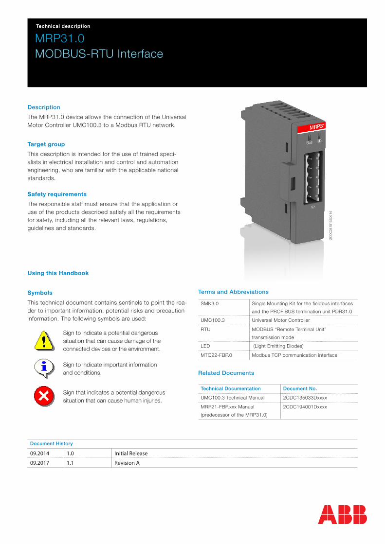
Description
The MRP31.0 device allows the connection of the Universal Motor Controller UMC100.3 to a Modbus RTU network.
MRP31.0MODBUS-RTU Interface
Terms and Abbreviations
SMK3.0 Single Mounting Kit for the fieldbus interfaces
and the PROFIBUS termination unit PDR31.0
UMC100.3 Universal Motor Controller
RTU MODBUS “Remote Terminal Unit”
transmission mode
LED (Light Emitting Diodes)
MTQ22-FBP.0 Modbus TCP communication interface
Related Documents
Technical Documentation Document No.
UMC100.3 Technical Manual 2CDC135033Dxxxx
MRP21-FBP.xxx Manual
(predecessor of the MRP31.0)
2CDC194001Dxxxx
Document History
09.2014 1.0 Initial Release
09.2017 1.1 Revision A
2CD
C34
1016
S00
14

2 - Mapping Table Configurator MRP31.0 and UMC100.3 | Technical description
Overview
This chapter contains a short description of the RS-485 standard and the MRP31.0 Modbus Interface module.
RS485 Standard
RS-485 is a serial interface standard for communication over a twisted-pair cable. Because the RS-485 signal transmission is differential, it provides better protection against noise and longer transmission distances than the RS-232. RS-485 is a half-duplex multi-drop network, which means that multiple devices may reside on line. Only one transmitter may be active at any given time.The RS-485 standard specifies only the electrical characteristics one of the bus system.
The RS-485 transmission line consists of two wires, A and B. The signal transmission is based on the voltage difference between the wires. The potential difference between the two wires determines the logic state bit: when B is at higher voltage than A, the state is defined as bit 1 (data high) and when A is at higher voltage than B, the state is defined as bit 0 (data low).
Ground wire and cable shield should be connected to prevent common mode voltage between the network devices from drifting outside the allowable limits. RS-485 bus cable should be terminated with a 120 Ohm resistor on both ends to pre-vent signal reflection.
The MRP31.0 Modbus Interface
The MRP31.0 Modbus communication interface is an optional device for the UMC100.3 which enables the connection of the UMC100.3 to a RS-485 network. The MRP31.0 provides galvanic isolation between the UMC100.3 and the RS-485 network.
– Use operator panel UMC100-PAN on UMC100.3 to set bus address, baud rate and timeout of the Modbus communction. Parity and frame lenght are automatically detected
– MRP31.0 supports the RTU transmission mode only – MRP31.0 is considered as a slave on the Modbus RTU network. Only one master can communicate with the MRP31.0
at a time.
Through the interface you can:
– give control commands to the UMC100.3 (for example Start, Stop, Fault Reset) – read status information and actual process values from the UMC100.3 – read device diagnosis information
X3: Modbus connection
Status Indication LEDs
X3: Modbus connection
X1: Communication to UMC100.3
X2: 24V DC supply connection
Top View Side View
MRP31
Technical description | Mapping Table Configurator MRP31.0 and UMC100.3 - 3
Mechanical Installation
The Modbus adapter module MRP31.0 can be mounted either on the UMC100.3 itself or separately from the UMC100.3 using the single mounting kit (SMK3.0).
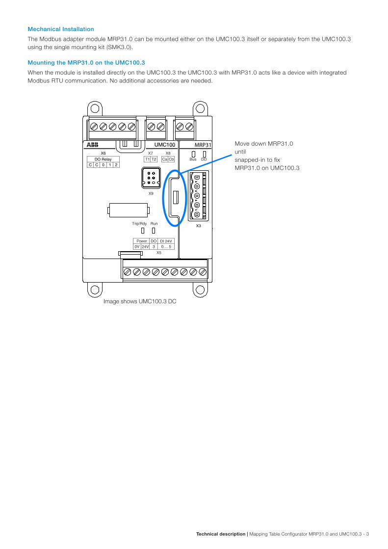
Mounting the MRP31.0 on the UMC100.3
When the module is installed directly on the UMC100.3 the UMC100.3 with MRP31.0 acts like a device with integrated Modbus RTU communication. No additional accessories are needed.
Move down MRP31.0 until snapped-in to fix MRP31.0 on UMC100.3
Image shows UMC100.3 DC
Power
MRP31
4 - Mapping Table Configurator MRP31.0 and UMC100.3 | Technical description
Mounting the MRP31.0 remote from the UMC100.3
When the communication interface is installed remote from the UMC100.3 - e. g. in the cable chamber of a motor control center - the MRP31.0 must be separately supplied. This makes it possible to keep the MRP31.0 online even in the case when the drawer is removed. Ready made cables are available. But it is also possible to use own cables.
For more details see section „Using MRP31.0 in a Drawout System“.
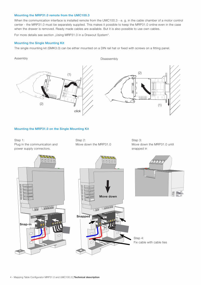
Mounting the Single Mounting Kit
The single mounting kit (SMK3.0) can be either mounted on a DIN rail hat or fixed with screws on a fitting panel.
Mounting the MRP31.0 on the Single Mounting Kit
Step 1: Plug in the communication and power supply connectors.
Step 3: Move down the MRP31.0 until snapped in
Step 2: Move down the MRP31.0
Snap-in
Snapped
Move down
Step 4: Fix cable with cable ties
Assembly Disassembly
(1)
(2)
(2)
(1)
Technical description | Mapping Table Configurator MRP31.0 and UMC100.3 - 5
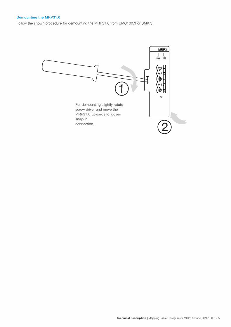
Demounting the MRP31.0
Follow the shown procedure for demounting the MRP31.0 from UMC100.3 or SMK.3.
For demounting slightly rotate screw driver and move the MRP31.0 upwards to loosen snap-in connection.
MRP31
6 - Mapping Table Configurator MRP31.0 and UMC100.3 | Technical description
Electrical installation
Modbus Connection
Connect Modbus to X3.
General cabling instructions
– Arrange the bus cables as far away from the motor cables as possible. – Avoid parallel runs – Use bushings at cable entries
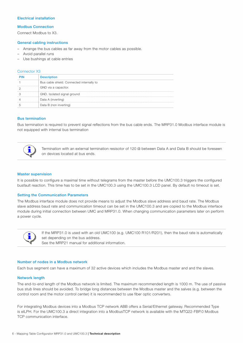
Connector X3
PIN Description
1 Bus cable shield. Connected internally to
GND via a capacitor.2
3 GND. Isolated signal ground
4 Data A (inverting)
5 Data B (non inverting)
Bus termination
Bus termination is required to prevent signal reflections from the bus cable ends. The MRP31.0 Modbus interface module is not equipped with internal bus termination
Termination with an external termination resisotor of 120 between Data A and Data B should be foreseen on devices located at bus ends.
Master supervision
It is possible to configure a maximal time without telegrams from the master before the UMC100.3 triggers the configured busfault reaction. This time has to be set in the UMC100.3 using the UMC100.3 LCD panel. By default no timeout is set.
Setting the Communication Parameters
The Modbus interface module does not provide means to adjust the Modbus slave address and baud rate. The Modbus slave address baud rate and communication timeout can be set in the UMC100.3 and are copied to the Modbus interface module during initial connection between UMC and MRP31.0. When changing communication parameters later on perform a power cycle.
If the MRP31.0 is used with an old UMC100 (e.g. UMC100 R101/R201), then the baud rate is automatically set depending on the bus address. See the MRP21 manual for additional information.
Number of nodes in a Modbus network
Each bus segment can have a maximum of 32 active devices which includes the Modbus master and and the slaves.
Network length
The end-to-end length of the Modbus network is limited. The maximum recommended length is 1000 m. The use of passive bus stub lines should be avoided. To bridge long distances between the Modbus master and the salves (e.g. between the control room and the motor control center) it is recommended to use fiber optic converters.
For integrating Modbus devices into a Modbus TCP network ABB offers a Serial/Ethernet gateway. Recommended Type is eILPH. For the UMC100.3 a direct integration into a ModbusTCP network is available with the MTQ22-FBP.0 Modbus TCP communication interface.
Technical description | Mapping Table Configurator MRP31.0 and UMC100.3 - 7
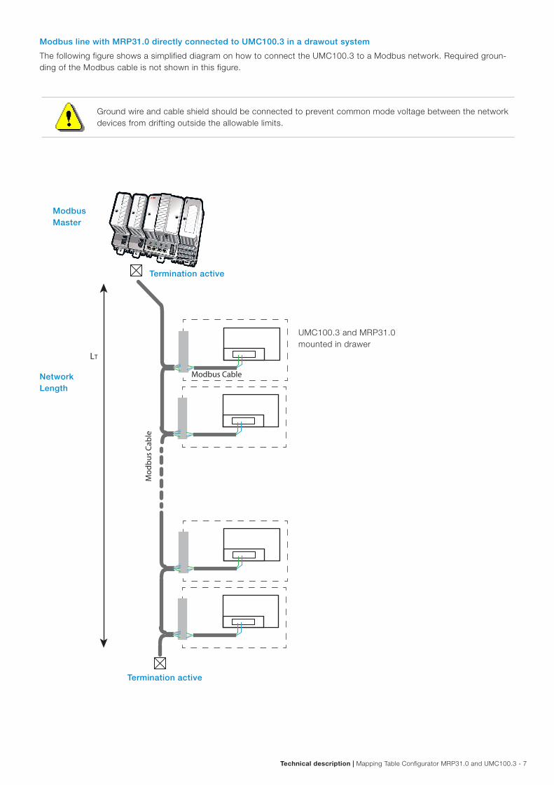
Modbus line with MRP31.0 directly connected to UMC100.3 in a drawout system
The following figure shows a simplified diagram on how to connect the UMC100.3 to a Modbus network. Required groun-ding of the Modbus cable is not shown in this figure.
UMC100.3 and MRP31.0 mounted in drawer
Termination active
Termination active
Ground wire and cable shield should be connected to prevent common mode voltage between the network devices from drifting outside the allowable limits.
Modbus Master
Network Length
Mod
bus
Cabl
e
Modbus Cable
LT
8 - Mapping Table Configurator MRP31.0 and UMC100.3 | Technical description
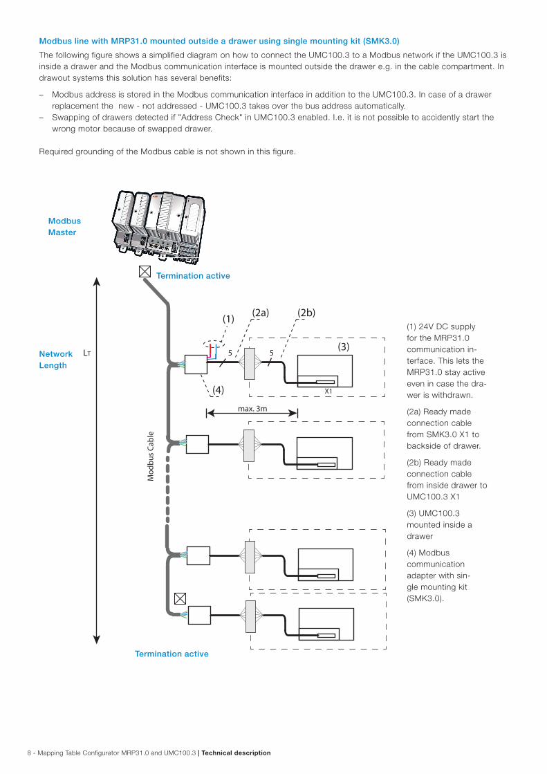
Modbus line with MRP31.0 mounted outside a drawer using single mounting kit (SMK3.0)
The following figure shows a simplified diagram on how to connect the UMC100.3 to a Modbus network if the UMC100.3 is inside a drawer and the Modbus communication interface is mounted outside the drawer e.g. in the cable compartment. In drawout systems this solution has several benefits:
– Modbus address is stored in the Modbus communication interface in addition to the UMC100.3. In case of a drawer replacement the new - not addressed - UMC100.3 takes over the bus address automatically.
– Swapping of drawers detected if "Address Check" in UMC100.3 enabled. I.e. it is not possible to accidently start the wrong motor because of swapped drawer.
Required grounding of the Modbus cable is not shown in this figure.
Modbus Master
Network Length
Termination active
(1) 24V DC supply for the MRP31.0 communication in-terface. This lets the MRP31.0 stay active even in case the dra-wer is withdrawn.
(2a) Ready made connection cable from SMK3.0 X1 to backside of drawer.
(2b) Ready made connection cable from inside drawer to UMC100.3 X1
(3) UMC100.3 mounted inside a drawer
(4) Modbus communication adapter with sin-gle mounting kit (SMK3.0).
Termination active
Mod
bus
Cabl
e
LT 55
X1
(2b)(1)
(3)
(4)
max. 3m
(2a)
Technical description | Mapping Table Configurator MRP31.0 and UMC100.3 - 9
Diagnosis
Diagnosis and behaviour in case of an error
The MRP31.0 module provides diagnosis information about the status of the connected UMC100.3, its own status and the status of the Modbus connection.
Diagnosis information is shown
– with the locally available LEDs and – via Modbus services.
Checklist
In case of trouble use the following checklist to track down the problem:
RS485
– Are the termination resistors placed at the end of the line? Never place any termination resistors on a drop cable.
– Is the line polarity correct? Are the lines by accident swapped? – Is the maximum line length exceeded?
MODBUS parameters
– Is the baud rate correctly adjusted? – Is the MODBUS master in RTU mode? – Is the slave address correct? – Are there two devices with the same address in the system?
MODBUS master
– Is the request to response timeout correct? – Is the MODBUS silent interval between two telegrams > 3.5 character times? – Notice that the slave device will not give any response when it is addressed with a broadcast (slave address = 0)
MODBUS slave
– Has the device a unique MODBUS address? – Same baud rate set as used in the master? – Is the function code supported? – Has the request a valid quantity of coils, inputs, registers? – Power supply turned on?
10 - Mapping Table Configurator MRP31.0 and UMC100.3 | Technical description
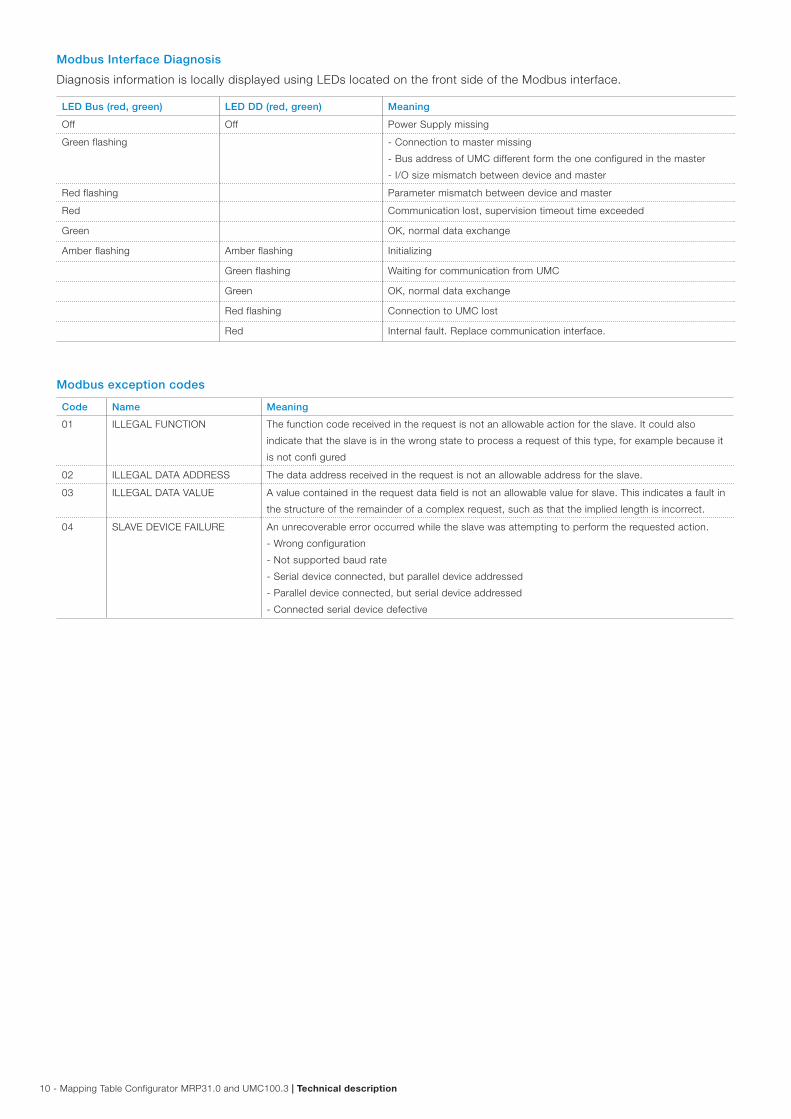
Modbus Interface Diagnosis
Diagnosis information is locally displayed using LEDs located on the front side of the Modbus interface.
LED Bus (red, green) LED DD (red, green) Meaning
Off Off Power Supply missing
Green flashing - Connection to master missing
- Bus address of UMC different form the one configured in the master
- I/O size mismatch between device and master
Red flashing Parameter mismatch between device and master
Red Communication lost, supervision timeout time exceeded
Green OK, normal data exchange
Amber flashing Amber flashing Initializing
Green flashing Waiting for communication from UMC
Green OK, normal data exchange
Red flashing Connection to UMC lost
Red Internal fault. Replace communication interface.
Modbus exception codes
Code Name Meaning
01 ILLEGAL FUNCTION The function code received in the request is not an allowable action for the slave. It could also
indicate that the slave is in the wrong state to process a request of this type, for example because it
is not confi gured
02 ILLEGAL DATA ADDRESS The data address received in the request is not an allowable address for the slave.
03 ILLEGAL DATA VALUE A value contained in the request data field is not an allowable value for slave. This indicates a fault in
the structure of the remainder of a complex request, such as that the implied length is incorrect.
04 SLAVE DEVICE FAILURE An unrecoverable error occurred while the slave was attempting to perform the requested action.
- Wrong configuration
- Not supported baud rate
- Serial device connected, but parallel device addressed
- Parallel device connected, but serial device addressed
- Connected serial device defective

Technical description | Mapping Table Configurator MRP31.0 and UMC100.3 - 11
Modbus communication and Register Map for UMC100.3
Devices on a Modbus network offer their data in registers to a Modbus master. There is the possibility to read or write sin-gle bits (coils) or whole words.(registers).
The following Modbus requests are generally supported:
Commands MODBUS Function Codes Starting address
Read binary input values FC 1 Read Coils
FC 2 Read Discrete Inputs
0000 Hex
Write binary output values FC 15 Write Multiple Coils
FC 5 Write Single Coil
0100 Hex
Read analog input values FC 3 Read Holding Registers
FC 4 Read Input Registers
0200 Hex
Write analog output values FC 16 Write Multiple Registers
FC 6 Write Single Register
0300 Hex
Read diagnostic data FC 3 Read Holding Registers
FC 4 Read Input Registers
2000 Hex
Return query data FC 8 Sub Function 00 n.a.
The following table shows in which registers the UMC100.3 data and diagnosis can be accessed:
Analog Inputs of UMC100.3 acc. to the UMC100.3 manual section A1 Parameters and Data Structures on a Fieldbus
Register Data
0x0200 Motor Current in % of Ie (0% - 800%
0x0201 Analog Word (Thermal Load: 0% - 100%)
0x0202 Analog Word (Time to trip in seconds)
0x0203 Analog Word (Time to restart in seconds)
0x0204 Analog Word (Active power in selected scale)
0x0205
DX1xx
DI7
DX1xx
DI6
DX1xx
DI5
DX1xx
DI4
DX1xx
DI3
DX1xx
DI2
DX1xx
DI1
DX1xx
DI0
- - Run Time
Exceeded1
Out of
Position1
Torque Open1 Torque
Closed1
End Pos
Open1
End Pos
Closed1
0x0206
U Imbal. warn U Imbal. trip Undervoltage
warn
Undervoltage
trip
Underpower
warn
Underpower
trip
Overpower
warn
Overpower
trip
Earth fault
warning
Earth fault trip Cooling time
running
- THD warning No start
possible5)
1 start left 5) More than 1
start left5)
Analog Outputs of UMC100.3 acc. to the UMC100.3 manual section A1 Parameters and Data Structures on a Fieldbus
Register Data
0x0300 Analog Word
0x0301 Analog Word
0x0302 Analog Word
0x0303 Analog Word

12 - Mapping Table Configurator MRP31.0 and UMC100.3 | Technical description
Access to the monitoring data of UMC100.3 acc. to the UMC100.3 manual section A1 Parameters and Data Structures on a Fieldbus
Register Bit 7
Bit 15
Bit 6 Bit 5 Bit 4 Bit 3 Bit 2 Bit1 Bit 0
Bit 8
0x0000
Summary
Warning
Summary
Fault
Local Control Reverse
Lockout
Time3
Overload
warning
Run Forward
/ Opening
Off Run
Reverse /
Closing
UMC100 DI5 UMC100 DI4 UMC100 DI3 UMC100 DI2 UMC100 DI1 UMC100 DI0 Run
Fast Forward
-
Access to the command data of UMC100.3 acc. to the UMC100.3 manual section A1 Parameters and Data Structures on a Fieldbus
Register Bit 7
Bit 15
Bit 23
Bit 31
Bit 6 Bit 5 Bit 4 Bit 3 Bit 2 Bit1 Bit 0
Bit 8
Bit 16
Bit 24
0x0100
- Fault Reset Auto Mode Prepare
Emergency
Start
- Run
Forward /
Opening
Off Run
Reverse /
Closing
UMC100 DO2 UMC100 DO1 UMC100 DO0 UMC100 24V
DC Out
- - Run
Fast Forward
-
0x0101
VI15x
DO0
- - - DX1xx
DO3
DX1xx
DO2
DX1xx
DO1
DX1xx
DO0
- - - - - - - -
Word oriented access to diagnosis data of UMC100.3 acc. to the UMC100.3 manual section A1 Parameters and Data Structures on a Fieldbus
Register Bit 7
Bit 15
Bit 6 Bit 5 Bit 4 Bit 3 Bit 2 Bit1 Bit 0
Bit 8
0x2000
Checkback
missing
PTC wiring
failure
PTC hot Pre-waring
thermal model
Locked rotor
during start-
up (stall)
Phase
imbalance1
Phase
loss1
Thermal
overload trip
Actuator
problem1
UMC
self-test error
Earth fault
pre-warning
Eart fault trip
(internal or
externally
triggered)
I
above high
current
warning
threshold
I
above high
current trip
threshold
I
below low
current
warning
threshold
I
below low
current trip
threshold
0x2001
Trip/Warning
from
Aux-Fault
function block
input 52)
Trip/Warning
from
Aux-Fault
function block
input 42)
Trip/Warning
from
Aux-Fault
function block
input 32)
Trip/Warning
from
Aux-Fault
function block
input 22)
Trip/Warning
from
AuxFault
function block
input 12)
HW fault on
IO module
Custom
application
error
IO module
missing
Warning
triggered from
AM2
Trip triggered
from AM2
Warning
triggered from
AM1
Trip triggered
from AM1
Trip triggered
from
Multifunction
input DI2
Trip triggered
from
Multifunction
input DI1
Trip triggered
from
Multifunction
input DI0
Trip / Warning
from AuxFault
function block
input 62)
0x2002
- - THD Warning Voltage out of
spec1
Overload
power
Underload
power1
- -
- - Cooling Time
Running
Just one start
left
Num Starts
Overrun
- - -
0x2003
Extended
diagnosis is
available1).
Parameter out
of range
- - - - - -
Fault code. See section "Error Handling, Maintenance and Service-> Fault Messages" for a description of the code.
Technical description | Mapping Table Configurator MRP31.0 and UMC100.3 - 13
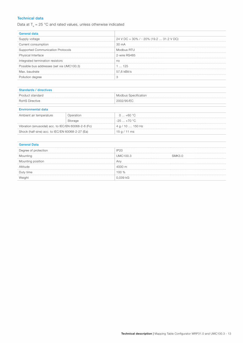
Technical data
Data at Ta = 25 °C and rated values, unless otherwise indicated
General data
Supply voltage 24 V DC + 30% / - 20% (19.2 … 31.2 V DC)
Current consumption 30 mA
Supported Communication Protocols Modbus RTU
Physical Interface 2-wire RS485
Integrated termination resistors no
Possible bus addresses (set via UMC100.3) 1 ... 125
Max. baudrate 57,6 kBit/s
Pollution degree 3
Standards / directives
Product standard Modbus Specification
RoHS Directive 2002/95/EC
Environmental data
Ambient air temperature Operation 0 ... +60 °C
Storage -25 ... +70 °C
Vibration (sinusoidal) acc. to IEC/EN 60068-2-6 (Fc) 4 g / 10 .... 150 Hz
Shock (half-sine) acc. to IEC/EN 60068-2-27 (Ea) 15 g / 11 ms
General Data
Degree of protection IP20
Mounting UMC100.3 SMK3.0
Mounting position Any
Altitude 4000 m
Duty time 100 %
Weight 0,039 kG

14 - Mapping Table Configurator MRP31.0 and UMC100.3 | Technical description
Dimensions
Connection Cables
Pin Color Function
5 Blue VDD
4 Brown VCC
3 Black Communication
2 Grey Communication
1 White Diagnosis
Colors must match
Pin Function
2 24 V DC
1 0 V DC
Drawer
to UMC100.3
SMK3.0
MRP31 / DNP31
22.5
89
64
99.7 0.886"
3.50
4"
2.52
0"
3.925"
1 2 5 4 3 2 1
12345
123456
CDP18.150
CDP24.150
X1
X2
X1X2
X1

Technical description | Mapping Table Configurator MRP31.0 and UMC100.3 - 15
Order codes
Order Code Type Description
1SAJ251000R0001 MRP31.0 Modbus RTU communication interface
1SAJ929600R0001 SMK3.0 * Single mounting kit for separate mounting of the communication interface
1SAJ929180R0015 CDP18.150 ** Cable between UMC100.3 and drawer inside, 1.5 m
1SAJ929240R0015 CDP24.150 ** Cable between SMK3.0 and drawer outside, 1.5 m
1SAJ929610R0001 SMK3-X2.10 Terminal block 2-pol. for SMK3.0 supply, 10 pcs
1SAJ929620R0001 SMK3-X1.10 Terminal block 5-pol. for SMK3.0 communication, 10 pcs
* is delivered including terminal block for power supply connection ** ready cables with terminal block on one end and one open end

ABB STOTZ-KONTAKT GmbHEppelheimer Straße 8269123 Heidelberg, GermanyPhone: +49 (0) 6221 7 01-0Fax: +49 (0) 6221 7 01-13 25E-mail: [email protected]
You can find the address of your local sales organisation on the ABB home pagehttp://www.abb.com/contacts -> Low Voltage Products and Systems
Contact us
Note:We reserve the right to make technical changes or modify the contents of this document without prior notice. With regard to purchase orders, the agreed particulars shall prevail. ABB AG does not accept any responsibility whatsoever for potential errors or possible lack of information in this document.
We reserve all rights in this document and in the subject matter and illustrations contained therein. Any reproduction, disclosure to third parties or utilization of its contents – in whole or in parts – is forbidden without prior written consent of ABB AG.
Copyright© 2017 ABB All rights reserved
2C
DC
1940
05D
0201
Rev
. A
09.2
017