technical bulletin - flowserve.de · mot tenifer treated distributing vot tenifer treated see page...
TRANSCRIPT
Experience in Motion
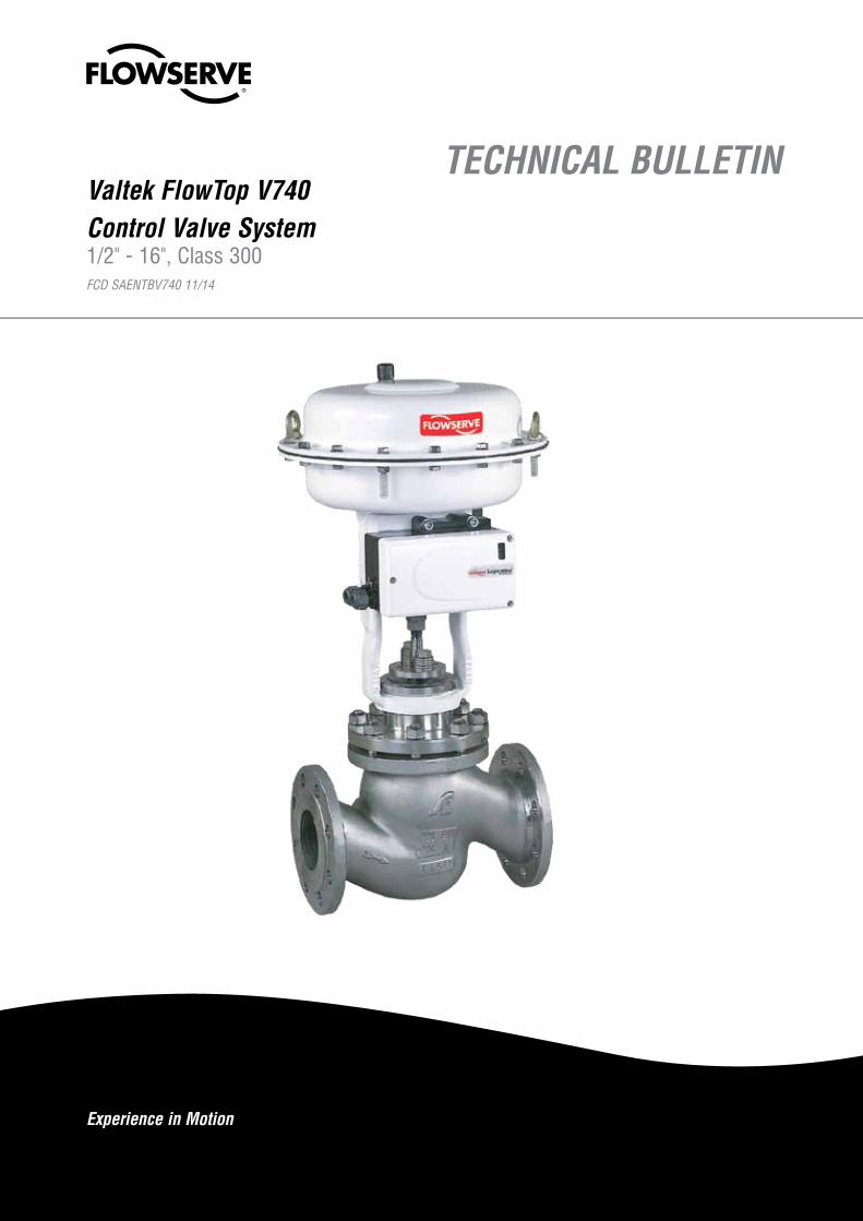
TECHNICAL BULLETINValtek FlowTop V740Control Valve System1/2" - 16", Class 300 FCD SAENTBV740 11/14

Valtek FlowTop FCD SAENTBV740 11/14
2
FlowTop - Features
Compact design up to six Spring Ranges available for use with or without a Positioner.
High quality long life springs properly aligned by spring plates.
Uninterrupted linear travel and no loss of operating force, due to reinforced rolling type diaphragm with minimum area variation during stroke.
High quality powder painted carbon steel actuator cases - ex-tremly corrosion re-sistant. Paint is du-rable and resistent to chipping or flaking.
Direct air supply is ported through the internal passage in the yoke. Avail-able only with direct mounting positioner or accessories on air to open applica-tion. No tubing is required.
PackingNine high quality packing designs are available. ( see page 13 )
BonnetTen different bonnet designs are available. Extremly robust design integral flange. ( see page 10 - 12 )
TrimEight standard trim designs and fourteen special trim designs are available.( see page 14 - 21 resp. Special Brochure )
BodyNine different body designs available. The enlarged gallery enables higher kvs per trim and valve size than competitive products.( see page 4 - 6 )
ActuatorFlowAct is the standard pneumaticlinear actuator. Further interfaces for:
• Haselhofer Electric linear Actuator• PSL Electric linear Actuator• Linear thrust Unit „light“ or „heavy“
for Electric multi turn Actuator• Manual Operation( see page 26, 27 )
A high quality du-rable solid ductile iron yoke is deliv-ered as standard. It´s a universal yoke which accepts different industry standard mountings available on the mar-ket.
The gasket seal provides practically between seat and body. Minimised vibration
and wear because of heavy duty solid, sturdy plug guiding.
Valtek FlowTop FCD SAENTBV740 11/14
3
flowserve.com
FlowTop - Advantages
Modular Design The same bodies can be used for various different types of bonnet, packing, trim and actua-tors. This concept of a modular valve design allows the reduction of spare parts and offers an interchangeable valve for all applications.
Tight Shut - Off FlowTop control valves offer Class IV shut-off as standard without the need for lapping plug and seat. Class VI shut-off is also available for FlowTop with a soft seat design.
Post guided One solid guide stabilises the stem and plug during valve travel and minimises vibration and wear. A double plug guiding is also available depending on the service application and the trim selection.
Compact Designed and engineered for applications with a limited installation envelope.
Low Noise andAnti - Cavitation Trim
SilentPack, MultiStream, Multi - Hole Plug, RLS, Silencer, reducing noise levels generated by vapours and gases and eliminating cavitation.
Versatile Packing Configuration
Available in PTFE and Graphite. Live loading kits are retrofittable without modification to the valve.
Fugitive Emissions Packing Environmental packing design is available in accordance with „TA-Luft“ up to + 450 °C operat-ing temperature.
Easy of Maintenance By using a seat ring gasket between the body and the seat, the FlowTop allows faster mainte-nance without the necessity to remachine the body seat surface. The top entry design allows the valve body to remain in line whilst the trim is changed or replaced.
Wide Variety of Trim Sizes Up to 17 kvs values per valve size.
Multifunction Yoke The standard multifunction yoke is designed to accept all of the standard mountings available on the market including NAMUR ( IEC 534.6 ) and the direct VDI / VDE 3847 / 3845 mounting.
High-Thrust Diaphragm The actuator is compact, light weight and suitable for 6 bar air supply; multiple spring combi-nations reduces installation size and initial expenditure.
Dynamic Stability Solid, sturdy plug head guiding minimises vibration and wear.
Certifications and Approvals( sample )
Quality assurance system certificated according to EN ISO 9001:2000 inc. product development.EC-Type - Examination according to PED 97/23/EC Module B + DATEX - Declaration of Conformity according Derictive 94/9/ECTA-Luft - Certificate and Fugitive Emission according ISO 15848-1SIL - Certificate according IEC 61508 DVGW - Certificate according EC Type Examination 90/396/EWGTR CU - Certificate according to Derictive TR CU 010/2011 (GOST-R)DNV - Type Approval
Multiple Application Usage High-performance, general-service control valve used in many process industries including chemical, refinery, power, food and beverage, HVAC.
Valtek FlowTop FCD SAENTBV740 11/14
4
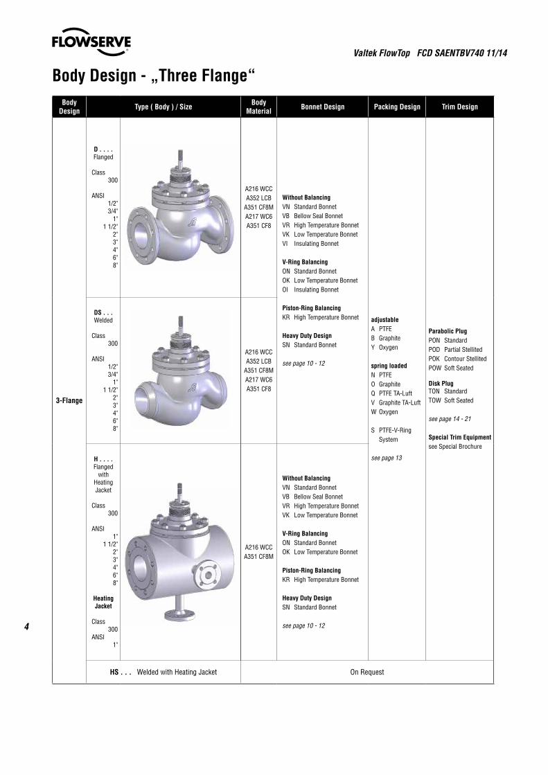
Body Design - „Three Flange“Body
Design Type ( Body ) / Size Body Material Bonnet Design Packing Design Trim Design
3-Flange
D . . . .Flanged
Class300
ANSI1/2"3/4"
1"1 1/2"
2"3"4"6"8"
A216 WCCA352 LCB
A351 CF8MA217 WC6A351 CF8
Without BalancingVN Standard BonnetVB Bellow Seal BonnetVR High Temperature BonnetVK Low Temperature BonnetVI Insulating Bonnet
V-Ring BalancingON Standard BonnetOK Low Temperature BonnetOI Insulating Bonnet
Piston-Ring BalancingKR High Temperature Bonnet
Heavy Duty DesignSN Standard Bonnet
see page 10 - 12
adjustableA PTFEB GraphiteY Oxygen
spring loadedN PTFEO GraphiteQ PTFE TA-LuftV Graphite TA-LuftW Oxygen
S PTFE-V-Ring System
see page 13
Parabolic PlugPON StandardPOD Partial StellitedPOK Contour StellitedPOW Soft Seated
Disk PlugTON StandardTOW Soft Seated
see page 14 - 21
Special Trim Equipmentsee Special Brochure
DS . . .Welded
Class300
ANSI1/2"3/4"
1"1 1/2"
2"3"4"6"8"
A216 WCCA352 LCB
A351 CF8MA217 WC6A351 CF8
H . . . .Flanged
withHeatingJacket
Class300
ANSI1"
1 1/2"2"3"4"6"8"
HeatingJacket
Class300
ANSI1"
A216 WCCA351 CF8M
Without BalancingVN Standard BonnetVB Bellow Seal BonnetVR High Temperature BonnetVK Low Temperature Bonnet
V-Ring BalancingON Standard BonnetOK Low Temperature Bonnet
Piston-Ring BalancingKR High Temperature Bonnet
Heavy Duty DesignSN Standard Bonnet
see page 10 - 12
HS . . . Welded with Heating Jacket On Request
Valtek FlowTop FCD SAENTBV740 11/14
5
flowserve.com
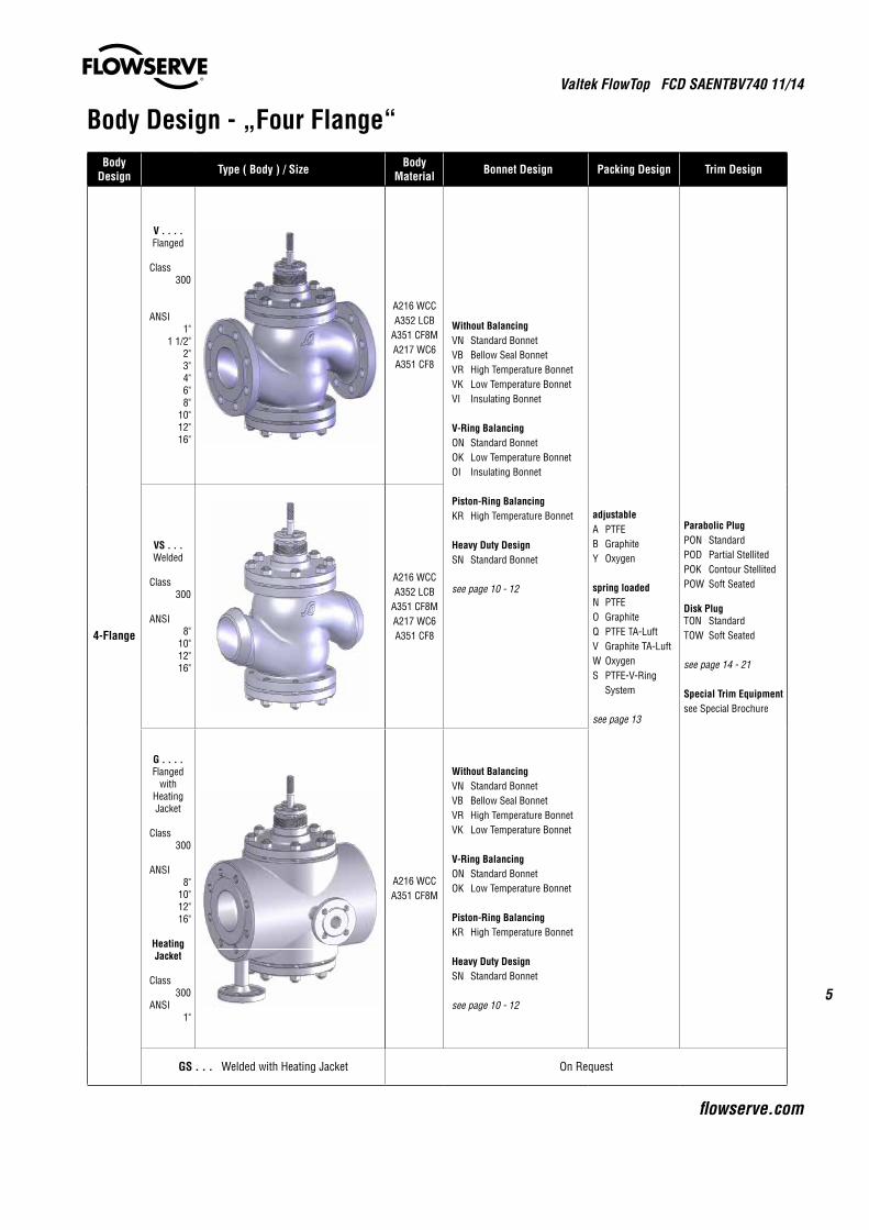
Body Design - „Four Flange“Body
Design Type ( Body ) / Size Body Material Bonnet Design Packing Design Trim Design
4-Flange
V . . . .Flanged
Class300
ANSI1"
1 1/2"2"3"4"6"8"
10"12"16"
A216 WCCA352 LCB
A351 CF8MA217 WC6A351 CF8
Without BalancingVN Standard BonnetVB Bellow Seal BonnetVR High Temperature BonnetVK Low Temperature BonnetVI Insulating Bonnet
V-Ring BalancingON Standard BonnetOK Low Temperature BonnetOI Insulating Bonnet
Piston-Ring BalancingKR High Temperature Bonnet
Heavy Duty DesignSN Standard Bonnet
see page 10 - 12
adjustableA PTFEB GraphiteY Oxygen
spring loadedN PTFEO GraphiteQ PTFE TA-LuftV Graphite TA-LuftW OxygenS PTFE-V-Ring System
see page 13
Parabolic PlugPON StandardPOD Partial StellitedPOK Contour StellitedPOW Soft Seated
Disk PlugTON StandardTOW Soft Seated
see page 14 - 21
Special Trim Equipmentsee Special Brochure
VS . . .Welded
Class300
ANSI8"
10"12"16"
A216 WCCA352 LCB
A351 CF8MA217 WC6A351 CF8
G . . . .Flanged
withHeatingJacket
Class300
ANSI8"
10"12"16"
HeatingJacket
Class300
ANSI1"
A216 WCCA351 CF8M
Without BalancingVN Standard BonnetVB Bellow Seal BonnetVR High Temperature BonnetVK Low Temperature Bonnet
V-Ring BalancingON Standard BonnetOK Low Temperature Bonnet
Piston-Ring BalancingKR High Temperature Bonnet
Heavy Duty DesignSN Standard Bonnet
see page 10 - 12
GS . . . Welded with Heating Jacket On Request
Valtek FlowTop FCD SAENTBV740 11/14
6
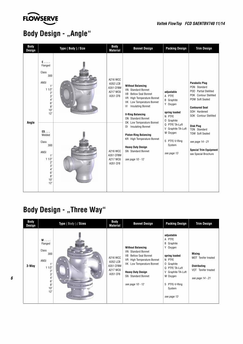
Body Design - „Angle“
Body Design Type ( Body ) / Size Body
Material Bonnet Design Packing Design Trim Design
Angle
E . . . .Flanged
Class300
ANSI1"
1 1/2"2"3"4"6"8"
10"12"
A216 WCCA352 LCB
A351 CF8MA217 WC6A351 CF8
Without BalancingVN Standard BonnetVB Bellow Seal BonnetVR High Temperature BonnetVK Low Temperature BonnetVI Insulating Bonnet
V-Ring BalancingON Standard BonnetOK Low Temperature BonnetOI Insulating Bonnet
Piston-Ring BalancingKR High Temperature Bonnet
Heavy Duty DesignSN Standard Bonnet
see page 10 - 12
adjustableA PTFEB GraphiteY Oxygen
spring loadedN PTFEO GraphiteQ PTFE TA-LuftV Graphite TA-LuftW Oxygen
S PTFE-V-Ring System
see page 13
Parabolic PlugPON StandardPOD Partial StellitedPOK Contour StellitedPOW Soft Seated
Contoured SeatSOH HardenedSOK Contour Stellited
Disk PlugTON StandardTOW Soft Seated
see page 14 - 21
Special Trim Equipmentsee Special Brochure
ES . . .Welded
Class300
ANSI1"
1 1/2"2"3"4"6"8"
10"12"
A216 WCCA351 CF8MA217 WC6A351 CF8
Body Design - „Three Way“Body
Design Type ( Body ) / Sizes Body Material Bonnet Design Packing Design Trim Design
3-Way
W . . . .Flanged
Class300
ANSI1"
1 1/2"2"3"4"6"8"
10"12"
A216 WCCA352 LCB
A351 CF8MA217 WC6A351 CF8
Without BalancingVN Standard BonnetVB Bellow Seal BonnetVR High Temperature BonnetVK Low Temperature Bonnet
Heavy Duty DesignSN Standard Bonnet
see page 10 - 12
adjustableA PTFEB GraphiteY Oxygen
spring loadedN PTFEO GraphiteQ PTFE TA-LuftV Graphite TA-LuftW Oxygen
S PTFE-V-Ring System
see page 13
MixingMOT Tenifer treated
DistributingVOT Tenifer treated
see page 14 - 21
Valtek FlowTop FCD SAENTBV740 11/14
7
flowserve.com
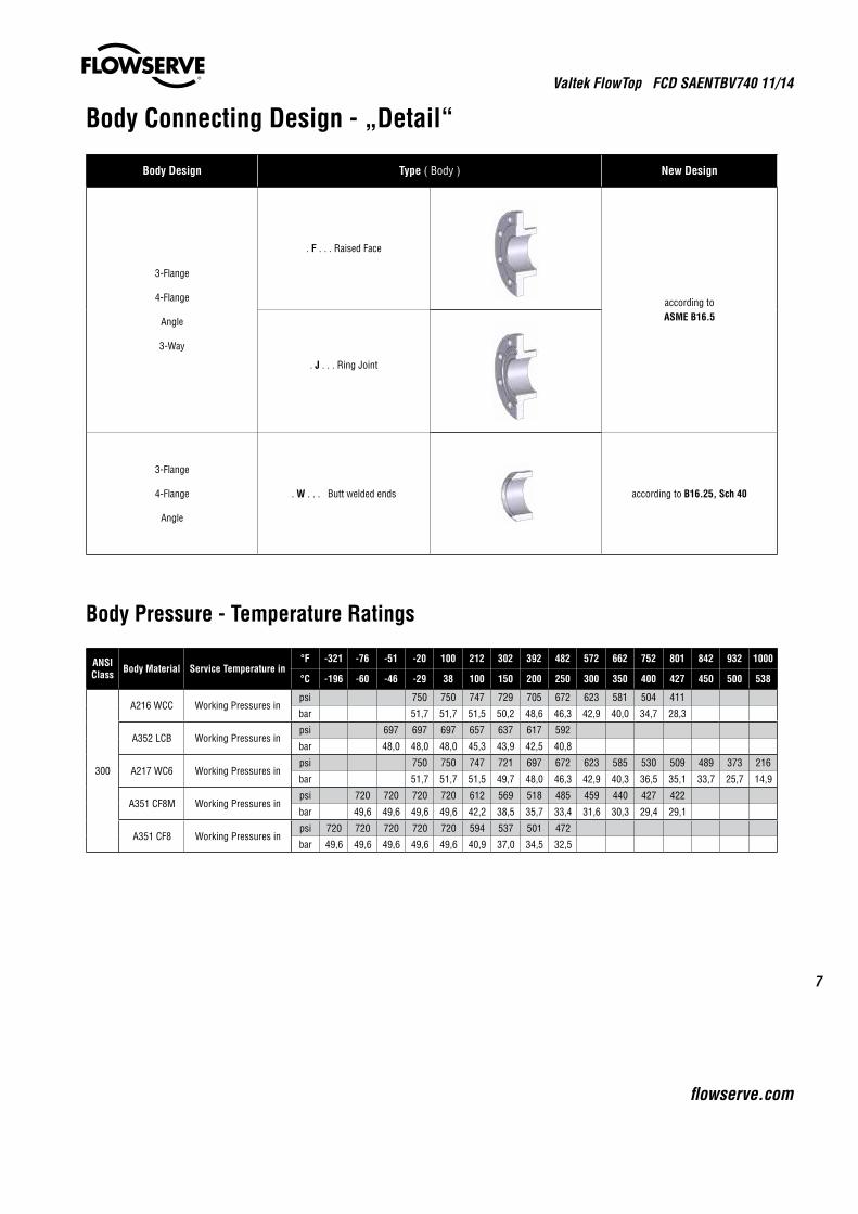
Body Connecting Design - „Detail“
Body Design Type ( Body ) New Design
3-Flange
4-Flange
Angle
3-Way
. F . . . Raised Face
according toASME B16.5
. J . . . Ring Joint
3-Flange
4-Flange
Angle
. W . . . Butt welded ends according to B16.25, Sch 40
Body Pressure - Temperature Ratings
ANSI Class Body Material Service Temperature in
°F -321 -76 -51 -20 100 212 302 392 482 572 662 752 801 842 932 1000
°C -196 -60 -46 -29 38 100 150 200 250 300 350 400 427 450 500 538
300
A216 WCC Working Pressures inpsi 750 750 747 729 705 672 623 581 504 411
bar 51,7 51,7 51,5 50,2 48,6 46,3 42,9 40,0 34,7 28,3
A352 LCB Working Pressures inpsi 697 697 697 657 637 617 592
bar 48,0 48,0 48,0 45,3 43,9 42,5 40,8
A217 WC6 Working Pressures inpsi 750 750 747 721 697 672 623 585 530 509 489 373 216
bar 51,7 51,7 51,5 49,7 48,0 46,3 42,9 40,3 36,5 35,1 33,7 25,7 14,9
A351 CF8M Working Pressures inpsi 720 720 720 720 612 569 518 485 459 440 427 422
bar 49,6 49,6 49,6 49,6 42,2 38,5 35,7 33,4 31,6 30,3 29,4 29,1
A351 CF8 Working Pressures inpsi 720 720 720 720 720 594 537 501 472
bar 49,6 49,6 49,6 49,6 49,6 40,9 37,0 34,5 32,5
Valtek FlowTop FCD SAENTBV740 11/14
8
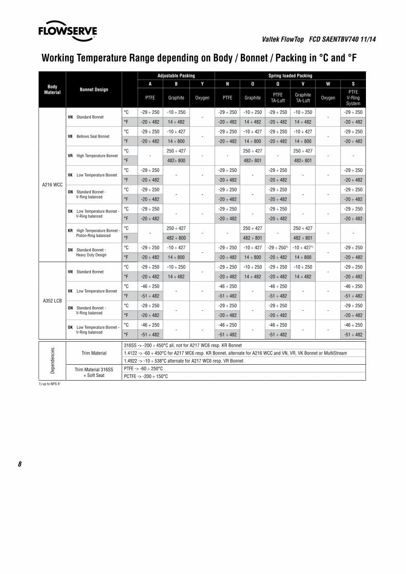
Working Temperature Range depending on Body / Bonnet / Packing in °C and °F
Body Material Bonnet Design
Adjustable Packing Spring loaded Packing
A B Y N O Q V W S
PTFE Graphite Oxygen PTFE Graphite PTFE TA-Luft
Graphite TA-Luft Oxygen
PTFE V-Ring System
A216 WCC
VN Standard Bonnet°C -29 ÷ 250 -10 ÷ 250
--29 ÷ 250 -10 ÷ 250 -29 ÷ 250 -10 ÷ 250
--29 ÷ 250
°F -20 ÷ 482 14 ÷ 482 -20 ÷ 482 14 ÷ 482 -20 ÷ 482 14 ÷ 482 -20 ÷ 482
VB Bellows Seal Bonnet°C -29 ÷ 250 -10 ÷ 427
--29 ÷ 250 -10 ÷ 427 -29 ÷ 250 -10 ÷ 427
--29 ÷ 250
°F -20 ÷ 482 14 ÷ 800 -20 ÷ 482 14 ÷ 800 -20 ÷ 482 14 ÷ 800 -20 ÷ 482
VR High Temperature Bonnet°C
-250 ÷ 427
- -250 ÷ 427
-250 ÷ 427
- -°F 482÷ 800 482÷ 801 482÷ 801
VK Low Temperature Bonnet°C -29 ÷ 250
- --29 ÷ 250
--29 ÷ 250
- --29 ÷ 250
°F -20 ÷ 482 -20 ÷ 482 -20 ÷ 482 -20 ÷ 482
ON Standard Bonnet - V-Ring balanced
°C -29 ÷ 250- -
-29 ÷ 250-
-29 ÷ 250- -
-29 ÷ 250
°F -20 ÷ 482 -20 ÷ 482 -20 ÷ 482 -20 ÷ 482
OK Low Temperature Bonnet - V-Ring balanced
°C -29 ÷ 250- -
-29 ÷ 250-
-29 ÷ 250- -
-29 ÷ 250
°F -20 ÷ 482 -20 ÷ 482 -20 ÷ 482 -20 ÷ 482
KR High Temperature Bonnet - Piston-Ring balanced
°C-
250 ÷ 427- -
250 ÷ 427-
250 ÷ 427- -
°F 482 ÷ 800 482 ÷ 801 482 ÷ 801
SN Standard Bonnet - Heavy Duty Design
°C -29 ÷ 250 -10 ÷ 427-
-29 ÷ 250 -10 ÷ 427 -29 ÷ 2501) -10 ÷ 4271)
--29 ÷ 250
°F -20 ÷ 482 14 ÷ 800 -20 ÷ 482 14 ÷ 800 -20 ÷ 482 14 ÷ 800 -20 ÷ 482
A352 LCB
VN Standard Bonnet°C -29 ÷ 250 -10 ÷ 250
--29 ÷ 250 -10 ÷ 250 -29 ÷ 250 -10 ÷ 250
--29 ÷ 250
°F -20 ÷ 482 14 ÷ 482 -20 ÷ 482 14 ÷ 482 -20 ÷ 482 14 ÷ 482 -20 ÷ 482
VK Low Temperature Bonnet°C -46 ÷ 250
- --46 ÷ 250
--46 ÷ 250
- --46 ÷ 250
°F -51 ÷ 482 -51 ÷ 482 -51 ÷ 482 -51 ÷ 482
ON Standard Bonnet - V-Ring balanced
°C -29 ÷ 250- -
-29 ÷ 250-
-29 ÷ 250- -
-29 ÷ 250
°F -20 ÷ 482 -20 ÷ 482 -20 ÷ 482 -20 ÷ 482
OK Low Temperature Bonnet - V-Ring balanced
°C -46 ÷ 250- -
-46 ÷ 250-
-46 ÷ 250- -
-46 ÷ 250
°F -51 ÷ 482 -51 ÷ 482 -51 ÷ 482 -51 ÷ 482
Depe
nden
cies Trim Material
316SS -> -200 ÷ 450°C all, not for A217 WC6 resp. KR Bonnet
1.4122 -> -60 ÷ 450°C for A217 WC6 resp. KR Bonnet, alternate for A216 WCC and VN, VR, VK Bonnet or MultiStream
1.4922 -> -10 ÷ 538°C alternate for A217 WC6 resp. VR Bonnet
Trim Material 316SS + Soft Seat
PTFE -> -60 ÷ 250°C
PCTFE -> -200 ÷ 150°C1) up to NPS 6"
Valtek FlowTop FCD SAENTBV740 11/14
9
flowserve.com
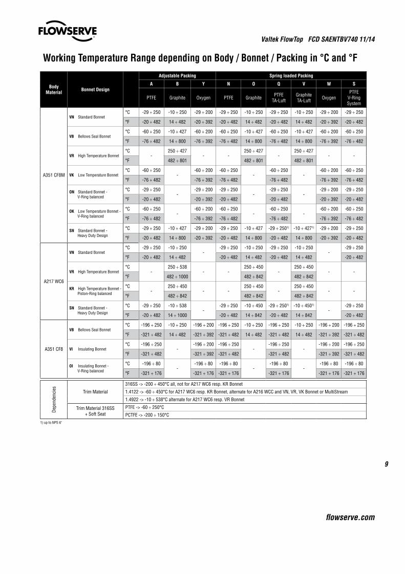
Working Temperature Range depending on Body / Bonnet / Packing in °C and °F
Body Material Bonnet Design
Adjustable Packing Spring loaded Packing
A B Y N O Q V W S
PTFE Graphite Oxygen PTFE Graphite PTFE TA-Luft
Graphite TA-Luft Oxygen
PTFE V-Ring System
A351 CF8M
VN Standard Bonnet°C -29 ÷ 250 -10 ÷ 250 -29 ÷ 200 -29 ÷ 250 -10 ÷ 250 -29 ÷ 250 -10 ÷ 250 -29 ÷ 200 -29 ÷ 250
°F -20 ÷ 482 14 ÷ 482 -20 ÷ 392 -20 ÷ 482 14 ÷ 482 -20 ÷ 482 14 ÷ 482 -20 ÷ 392 -20 ÷ 482
VB Bellows Seal Bonnet°C -60 ÷ 250 -10 ÷ 427 -60 ÷ 200 -60 ÷ 250 -10 ÷ 427 -60 ÷ 250 -10 ÷ 427 -60 ÷ 200 -60 ÷ 250
°F -76 ÷ 482 14 ÷ 800 -76 ÷ 392 -76 ÷ 482 14 ÷ 800 -76 ÷ 482 14 ÷ 800 -76 ÷ 392 -76 ÷ 482
VR High Temperature Bonnet°C
-250 ÷ 427
- -250 ÷ 427
-250 ÷ 427
- -°F 482 ÷ 801 482 ÷ 801 482 ÷ 801
VK Low Temperature Bonnet°C -60 ÷ 250
--60 ÷ 200 -60 ÷ 250
--60 ÷ 250
--60 ÷ 200 -60 ÷ 250
°F -76 ÷ 482 -76 ÷ 392 -76 ÷ 482 -76 ÷ 482 -76 ÷ 392 -76 ÷ 482
ON Standard Bonnet - V-Ring balanced
°C -29 ÷ 250-
-29 ÷ 200 -29 ÷ 250-
-29 ÷ 250-
-29 ÷ 200 -29 ÷ 250
°F -20 ÷ 482 -20 ÷ 392 -20 ÷ 482 -20 ÷ 482 -20 ÷ 392 -20 ÷ 482
OK Low Temperature Bonnet - V-Ring balanced
°C -60 ÷ 250-
-60 ÷ 200 -60 ÷ 250-
-60 ÷ 250-
-60 ÷ 200 -60 ÷ 250
°F -76 ÷ 482 -76 ÷ 392 -76 ÷ 482 -76 ÷ 482 -76 ÷ 392 -76 ÷ 482
SN Standard Bonnet - Heavy Duty Design
°C -29 ÷ 250 -10 ÷ 427 -29 ÷ 200 -29 ÷ 250 -10 ÷ 427 -29 ÷ 2501) -10 ÷ 4271) -29 ÷ 200 -29 ÷ 250
°F -20 ÷ 482 14 ÷ 800 -20 ÷ 392 -20 ÷ 482 14 ÷ 800 -20 ÷ 482 14 ÷ 800 -20 ÷ 392 -20 ÷ 482
A217 WC6
VN Standard Bonnet°C -29 ÷ 250 -10 ÷ 250
--29 ÷ 250 -10 ÷ 250 -29 ÷ 250 -10 ÷ 250
--29 ÷ 250
°F -20 ÷ 482 14 ÷ 482 -20 ÷ 482 14 ÷ 482 -20 ÷ 482 14 ÷ 482 -20 ÷ 482
VR High Temperature Bonnet°C
-250 ÷ 538
- -250 ÷ 450
-250 ÷ 450
- -°F 482 ÷ 1000 482 ÷ 842 482 ÷ 842
KR High Temperature Bonnet - Piston-Ring balanced
°C-
250 ÷ 450- -
250 ÷ 450-
250 ÷ 450- -
°F 482 ÷ 842 482 ÷ 842 482 ÷ 842
SN Standard Bonnet - Heavy Duty Design
°C -29 ÷ 250 -10 ÷ 538-
-29 ÷ 250 -10 ÷ 450 -29 ÷ 2501) -10 ÷ 4501)
--29 ÷ 250
°F -20 ÷ 482 14 ÷ 1000 -20 ÷ 482 14 ÷ 842 -20 ÷ 482 14 ÷ 842 -20 ÷ 482
A351 CF8
VB Bellows Seal Bonnet°C -196 ÷ 250 -10 ÷ 250 -196 ÷ 200 -196 ÷ 250 -10 ÷ 250 -196 ÷ 250 -10 ÷ 250 -196 ÷ 200 -196 ÷ 250
°F -321 ÷ 482 14 ÷ 482 -321 ÷ 392 -321 ÷ 482 14 ÷ 482 -321 ÷ 482 14 ÷ 482 -321 ÷ 392 -321 ÷ 482
VI Insulating Bonnet°C -196 ÷ 250
--196 ÷ 200 -196 ÷ 250
--196 ÷ 250
--196 ÷ 200 -196 ÷ 250
°F -321 ÷ 482 -321 ÷ 392 -321 ÷ 482 -321 ÷ 482 -321 ÷ 392 -321 ÷ 482
OI Insulating Bonnet - V-Ring balanced
°C -196 ÷ 80-
-196 ÷ 80 -196 ÷ 80-
-196 ÷ 80-
-196 ÷ 80 -196 ÷ 80
°F -321 ÷ 176 -321 ÷ 176 -321 ÷ 176 -321 ÷ 176 -321 ÷ 176 -321 ÷ 176
Depe
nden
cies Trim Material
316SS -> -200 ÷ 450°C all, not for A217 WC6 resp. KR Bonnet
1.4122 -> -60 ÷ 450°C for A217 WC6 resp. KR Bonnet, alternate for A216 WCC and VN, VR, VK Bonnet or MultiStream
1.4922 -> -10 ÷ 538°C alternate for A217 WC6 resp. VR Bonnet
Trim Material 316SS + Soft Seat
PTFE -> -60 ÷ 250°C
PCTFE -> -200 ÷ 150°C1) up to NPS 6"
Valtek FlowTop FCD SAENTBV740 11/14
10
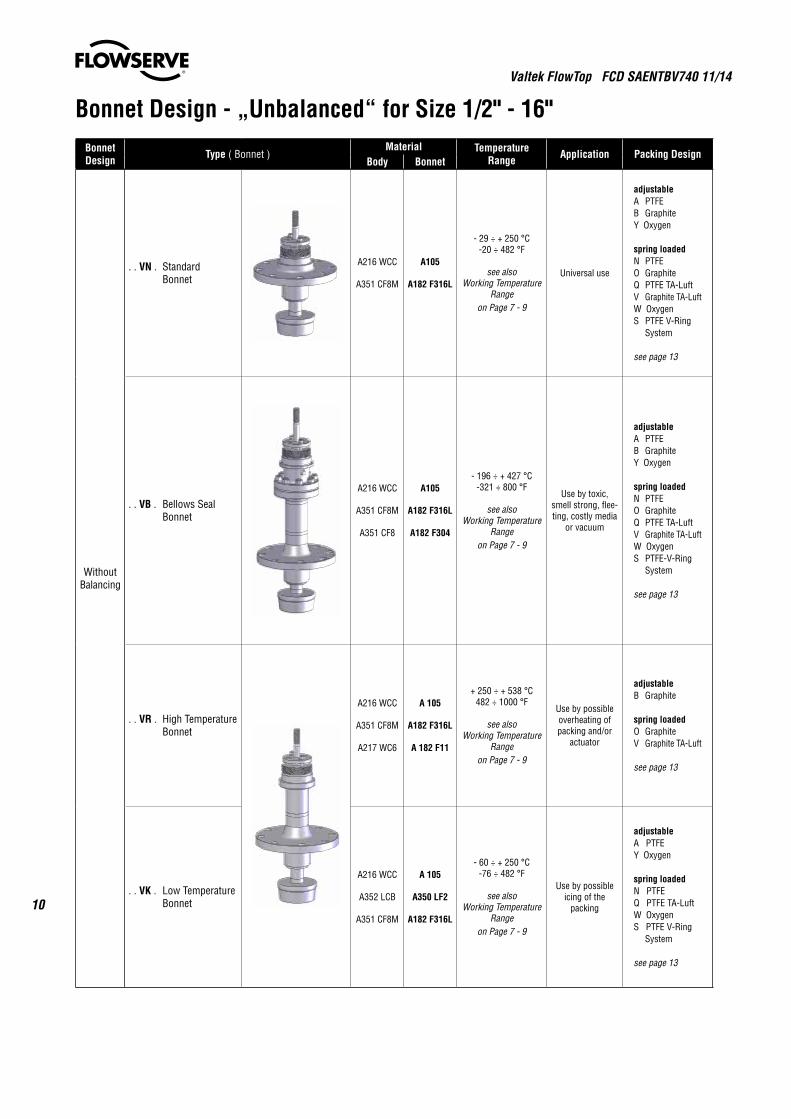
Bonnet Design - „Unbalanced“ for Size 1/2" - 16"Bonnet Design Type ( Bonnet )
Material Temperature Range Application Packing Design
Body Bonnet
WithoutBalancing
. . VN . StandardBonnet
A216 WCC
A351 CF8M
A105
A182 F316L
- 29 ÷ + 250 °C-20 ÷ 482 °F
see alsoWorking Temperature
Rangeon Page 7 - 9
Universal use
adjustableA PTFEB GraphiteY Oxygen
spring loadedN PTFEO GraphiteQ PTFE TA-LuftV Graphite TA-LuftW OxygenS PTFE V-Ring System
see page 13
. . VB . Bellows Seal Bonnet
A216 WCC
A351 CF8M
A351 CF8
A105
A182 F316L
A182 F304
- 196 ÷ + 427 °C-321 ÷ 800 °F
see alsoWorking Temperature
Rangeon Page 7 - 9
Use by toxic, smell strong, flee-ting, costly media
or vacuum
adjustableA PTFEB GraphiteY Oxygen
spring loadedN PTFEO GraphiteQ PTFE TA-LuftV Graphite TA-LuftW OxygenS PTFE-V-Ring System
see page 13
. . VR . High Temperature Bonnet
A216 WCC
A351 CF8M
A217 WC6
A 105
A182 F316L
A 182 F11
+ 250 ÷ + 538 °C482 ÷ 1000 °F
see alsoWorking Temperature
Rangeon Page 7 - 9
Use by possible overheating of packing and/or
actuator
adjustableB Graphite
spring loadedO GraphiteV Graphite TA-Luft
see page 13
. . VK . Low Temperature Bonnet
A216 WCC
A352 LCB
A351 CF8M
A 105
A350 LF2
A182 F316L
- 60 ÷ + 250 °C-76 ÷ 482 °F
see alsoWorking Temperature
Rangeon Page 7 - 9
Use by possible icing of the
packing
adjustableA PTFEY Oxygen
spring loadedN PTFEQ PTFE TA-LuftW OxygenS PTFE V-Ring System
see page 13
Valtek FlowTop FCD SAENTBV740 11/14
11
flowserve.com
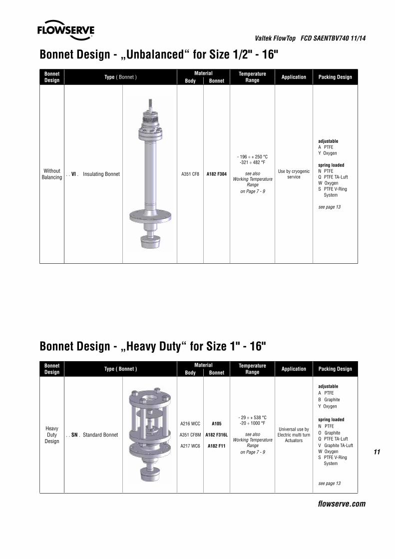
Bonnet Design - „Unbalanced“ for Size 1/2" - 16"Bonnet Design Type ( Bonnet )
Material Temperature Range Application Packing Design
Body Bonnet
WithoutBalancing . . VI . Insulating Bonnet A351 CF8 A182 F304
- 196 ÷ + 250 °C-321 ÷ 482 °F
see alsoWorking Temperature
Rangeon Page 7 - 9
Use by cryogenic service
adjustableA PTFEY Oxygen
spring loadedN PTFEQ PTFE TA-LuftW OxygenS PTFE V-Ring System
see page 13
Bonnet Design - „Heavy Duty“ for Size 1" - 16"Bonnet Design Type ( Bonnet )
Material Temperature Range Application Packing Design
Body Bonnet
Heavy Duty
Design. . SN . Standard Bonnet
A216 WCC
A351 CF8M
A217 WC6
A105
A182 F316L
A182 F11
- 29 ÷ + 538 °C-20 ÷ 1000 °F
see alsoWorking Temperature
Rangeon Page 7 - 9
Universal use byElectric multi turn
Actuators
adjustableA PTFEB GraphiteY Oxygen
spring loadedN PTFEO GraphiteQ PTFE TA-LuftV Graphite TA-LuftW OxygenS PTFE V-Ring System
see page 13
Valtek FlowTop FCD SAENTBV740 11/14
12
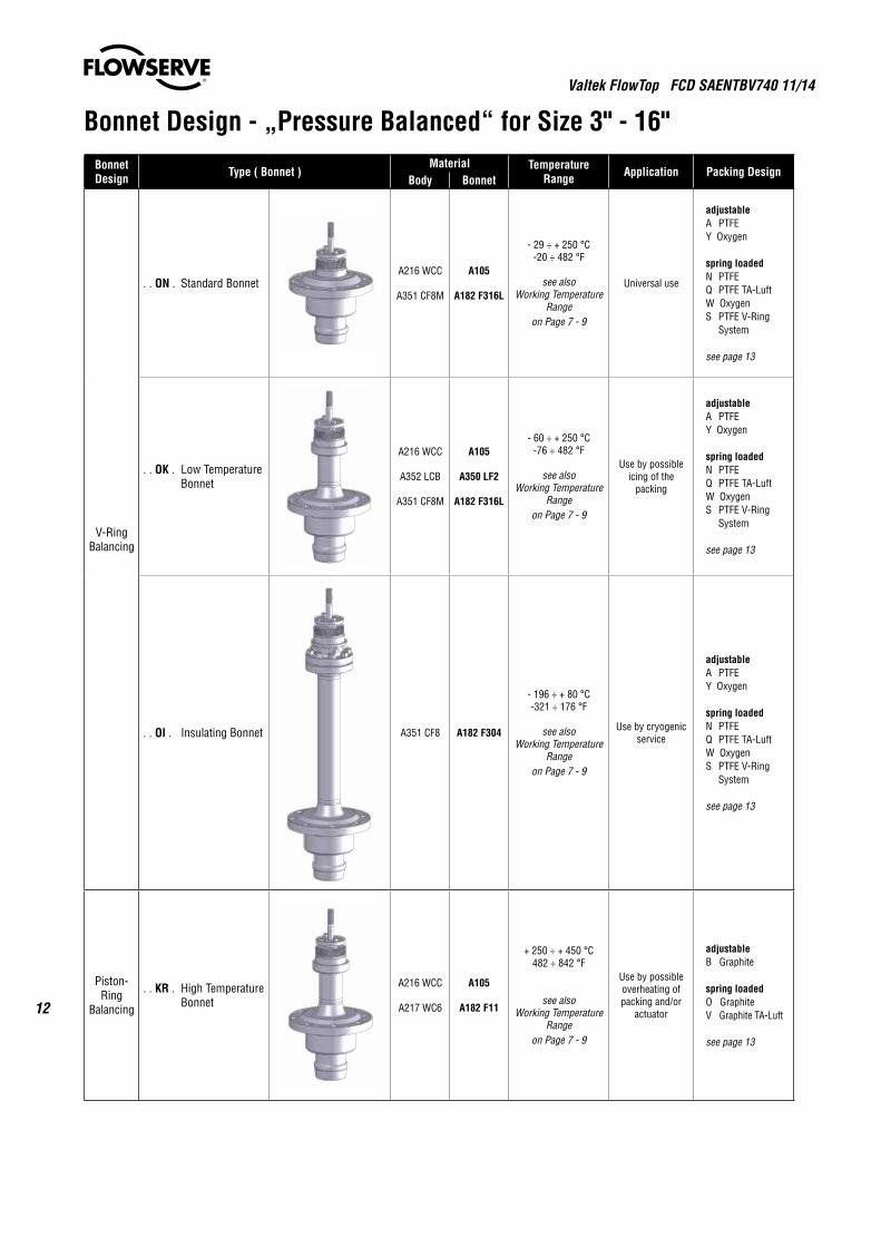
Bonnet Design - „Pressure Balanced“ for Size 3" - 16" Bonnet Design Type ( Bonnet )
Material Temperature Range Application Packing Design
Body Bonnet
V-RingBalancing
. . ON . Standard BonnetA216 WCC
A351 CF8M
A105
A182 F316L
- 29 ÷ + 250 °C-20 ÷ 482 °F
see alsoWorking Temperature
Rangeon Page 7 - 9
Universal use
adjustableA PTFEY Oxygen
spring loadedN PTFEQ PTFE TA-LuftW OxygenS PTFE V-Ring System
see page 13
. . OK . Low Temperature Bonnet
A216 WCC
A352 LCB
A351 CF8M
A105
A350 LF2
A182 F316L
- 60 ÷ + 250 °C-76 ÷ 482 °F
see alsoWorking Temperature
Rangeon Page 7 - 9
Use by possible icing of the
packing
adjustableA PTFEY Oxygen
spring loadedN PTFEQ PTFE TA-LuftW OxygenS PTFE V-Ring System
see page 13
. . OI . Insulating Bonnet A351 CF8 A182 F304
- 196 ÷ + 80 °C-321 ÷ 176 °F
see alsoWorking Temperature
Rangeon Page 7 - 9
Use by cryogenic service
adjustableA PTFEY Oxygen
spring loadedN PTFEQ PTFE TA-LuftW OxygenS PTFE V-Ring System
see page 13
Piston-Ring
Balancing
. . KR . High Temperature Bonnet
A216 WCC
A217 WC6
A105
A182 F11
+ 250 ÷ + 450 °C482 ÷ 842 °F
see alsoWorking Temperature
Rangeon Page 7 - 9
Use by possible overheating of packing and/or
actuator
adjustableB Graphite
spring loadedO GraphiteV Graphite TA-Luft
see page 13
Valtek FlowTop FCD SAENTBV740 11/14
13
flowserve.com
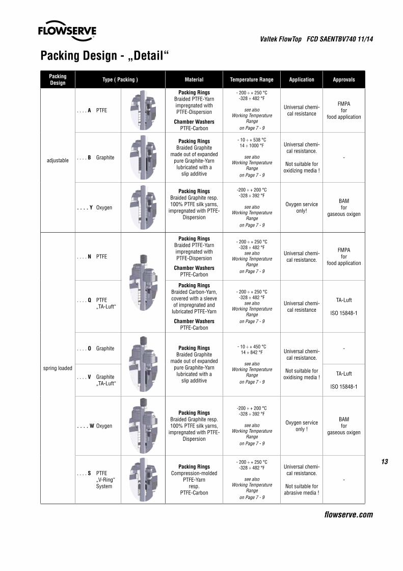
Packing Design - „Detail“Packing Design Type ( Packing ) Material Temperature Range Application Approvals
adjustable
. . . . A PTFE
Packing RingsBraided PTFE-Yarn impregnated withPTFE-Dispersion
Chamber WashersPTFE-Carbon
- 200 ÷ + 250 °C-328 ÷ 482 °F
see alsoWorking Temperature
Rangeon Page 7 - 9
Universal chemi-cal resistance
FMPAfor
food application
. . . . B Graphite
Packing RingsBraided Graphite
made out of expanded pure Graphite-Yarnlubricated with a
slip additive
- 10 ÷ + 538 °C14 ÷ 1000 °F
see alsoWorking Temperature
Rangeon Page 7 - 9
Universal chemi-cal resistance.
Not suitable for oxidizing media !
-
. . . . Y Oxygen
Packing RingsBraided Graphite resp.100% PTFE silk yarns,
impregnated with PTFE-Dispersion
-200 ÷ + 200 °C-328 ÷ 392 °F
see alsoWorking Temperature
Rangeon Page 7 - 9
Oxygen service only!
BAMfor
gaseous oxigen
spring loaded
. . . . N PTFE
Packing RingsBraided PTFE-Yarn impregnated withPTFE-Dispersion
Chamber WashersPTFE-Carbon
- 200 ÷ + 250 °C-328 ÷ 482 °F
see alsoWorking Temperature
Rangeon Page 7 - 9
Universal chemi-cal resistance.
FMPAfor
food application
. . . . Q PTFE „TA-Luft“
Packing RingsBraided Carbon-Yarn, covered with a sleeve of impregnated and
lubricated PTFE-Yarn
Chamber WashersPTFE-Carbon
- 200 ÷ + 250 °C-328 ÷ 482 °F
see alsoWorking Temperature
Rangeon Page 7 - 9
Universal chemi-cal resistance
TA-Luft
ISO 15848-1
. . . . O Graphite Packing RingsBraided Graphite
made out of expanded pure Graphite-Yarnlubricated with a
slip additive
- 10 ÷ + 450 °C14 ÷ 842 °F
see alsoWorking Temperature
Rangeon Page 7 - 9
Universal chemi-cal resistance.
Not suitable for oxidising media !
-
. . . . V Graphite „TA-Luft“
TA-Luft
ISO 15848-1
. . . . W Oxygen
Packing RingsBraided Graphite resp.100% PTFE silk yarns,
impregnated with PTFE-Dispersion
-200 ÷ + 200 °C-328 ÷ 392 °F
see alsoWorking Temperature
Rangeon Page 7 - 9
Oxygen service only !
BAMfor
gaseous oxigen
. . . . S PTFE „V-Ring“ System
Packing RingsCompression-molded
PTFE-Yarnresp.
PTFE-Carbon
- 200 ÷ + 250 °C-328 ÷ 482 °F
see alsoWorking Temperature
Rangeon Page 7 - 9
Universal chemi-cal resistance.
Not suitable for abrasive media !
-
Valtek FlowTop FCD SAENTBV740 11/14
14
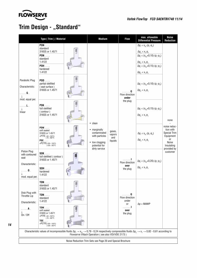
Trim Design - „Standard“
Type ( Trim ) / Material Medium Flow max. allowableDifferential Pressure
NoiseReduction
Parabolic Plug
Characteristic:
. . . . . G . ↓mod. equal per.
. . . . . L . ↓linear
PON . . . .standard316SS or 1.4571
• clean
• marginally contaminated with particles
• lowclogging potential for dirty service
gases, vapors
andliquids
. . . . . . GFlow direction
underthe plug
∆pI < xFZ·(p1-pV)
∆pC < xT·p1
none-
noise reduc-tion with
Special Trim Equipment
orNoise
Insulatingprovided by customer
PON . . . .standard1.4122
∆pI < (xFZ+0,10)·(p1-pV)
∆pC < xT·p1
POH . . . .hardened1.4122
∆pI < (xFZ+0,15)·(p1-pV)
∆pC < xT·p1
POD . . . .partial stellited( seat surface )316SS or 1.4571
∆pI < (xFZ+0,10)·(p1-pV)
∆pC < xT·p1
POK . . . .full stellited( contour )316SS or 1.4571
∆pI < (xFZ+0,15)·(p1-pV)
∆pC < xT·p1
POW . . . .soft seated316SS or 1.4571+PTFE (-60 ÷ 250°C) (-76 ÷ 482°F)
POC . . . .+PCTFE(-200 ÷ 150°C) (-328 ÷ 302°F)
∆pI < xFZ·(p1-pV)
∆pC < xT·p1
Piston Plug with contoured seat
Characteristic:
. . . . . G . ↓ mod. equal per.
SOK . . . .full stellited ( contour )316SS or 1.4571 . . . . . . I
Flow direction over
the plug
∆pI < (xFZ+0,20)·(p1-pV)
∆pC < xT·p1SOH . . . .hardened1.4122
Disk Plug with Throttle Lip
Characteristic:
. . . . . A . ↓ On / Off
TON . . . .standard316SS or 1.4571
. . . . . . GFlow direction
underor
. . . . . . Iover
the plug
∆p < MAWP
TON . . . .standard1.4122
TOW . . . .soft seated316SS or 1.4571+PTFE (-60 ÷ 250°C) (-76 ÷ 482°F)
TOC . . . .+PCTFE(-200 ÷ 150°C) (-328 ÷ 302°F)
Characteristic values of incompressible fluids ∆pI → xFZ → 0,79 - 0,24 respectively compressible fluids ∆pC → xT → 0,82 - 0,61 according to Flowserve Villach Operation ( see also VDI/VDE 2173 )
Noise Reduction Trim Sets see Page 20 and Special Brochure
Valtek FlowTop FCD SAENTBV740 11/14
15
flowserve.com
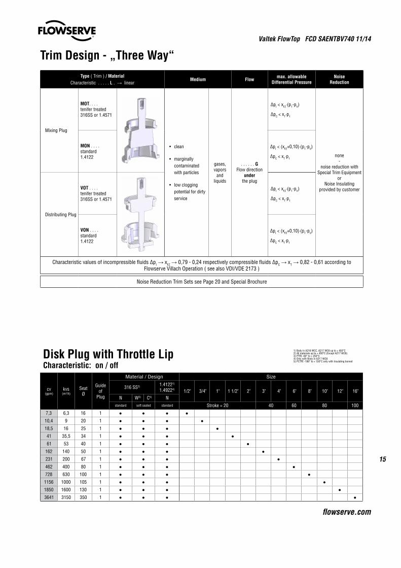
Disk Plug with Throttle LipCharacteristic: on / off
cv(gpm)
kvs(m3/h)
SeatØ
Guide of
Plug
Material / Design Size
316 SS2) 1.41221)
1.49224) 1/2" 3/4" 1" 1 1/2" 2" 3" 4" 6" 8" 10" 12" 16"N W3) C5) N
standard soft seated standard Stroke = 20 40 60 80 100
7,3 6,3 16 1 10,4 9 20 1 18,5 16 25 1 41 35,5 34 1 61 53 40 1
162 140 50 1 231 200 67 1 462 400 80 1 728 630 100 1
1156 1000 105 1 1850 1600 130 1 3641 3150 350 1
1) Body in A216 WCC, A217 WC6 up to + 450°C2) All materials up to + 450°C (Except A217 WC6)3) PTFE -60° to + 250°C4) Only with Body in A217 WC65) PCTFE -196° to + 150°C only with Insulating bonnet
Trim Design - „Three Way“Type ( Trim ) / Material
Characteristic . . . . . L . → linearMedium Flow max. allowable
Differential PressureNoise
Reduction
Mixing Plug
MOT. . . .tenifer treated316SS or 1.4571
• clean
• marginally contaminated with particles
• lowclogging potential for dirty service
gases, vapors
andliquids
. . . . . . GFlow direction
underthe plug
∆pI < xFZ·(p1-pV)
∆pC < xT·p1
none-
noise reduction with Special Trim Equipment
orNoise Insulating
provided by customer
MON . . . .standard1.4122
∆pI < (xFZ+0,10)·(p1-pV)
∆pC < xT·p1
Distributing Plug
VOT . . . .tenifer treated316SS or 1.4571
∆pI < xFZ·(p1-pV)
∆pC < xT·p1
VON . . . .standard1.4122
∆pI < (xFZ+0,10)·(p1-pV)
∆pC < xT·p1
Characteristic values of incompressible fluids ∆pI → xFZ → 0,79 - 0,24 respectively compressible fluids ∆pC → xT → 0,82 - 0,61 according to Flowserve Villach Operation ( see also VDI/VDE 2173 )
Noise Reduction Trim Sets see Page 20 and Special Brochure
Valtek FlowTop FCD SAENTBV740 11/14
16
1) Piston-Ring balancing2) All materials up to + 450°C (Except A217WC6) With Heavy duty bonnet: only for body A351 CF8M3) Body in A216 WCC, A217 WC6 up to + 450°C4) Only with Body in A217 WC65) PTFE (- 60°C to + 250°C)6) PCTFE (- 196°C to + 150°C) only with Insulating bonnet
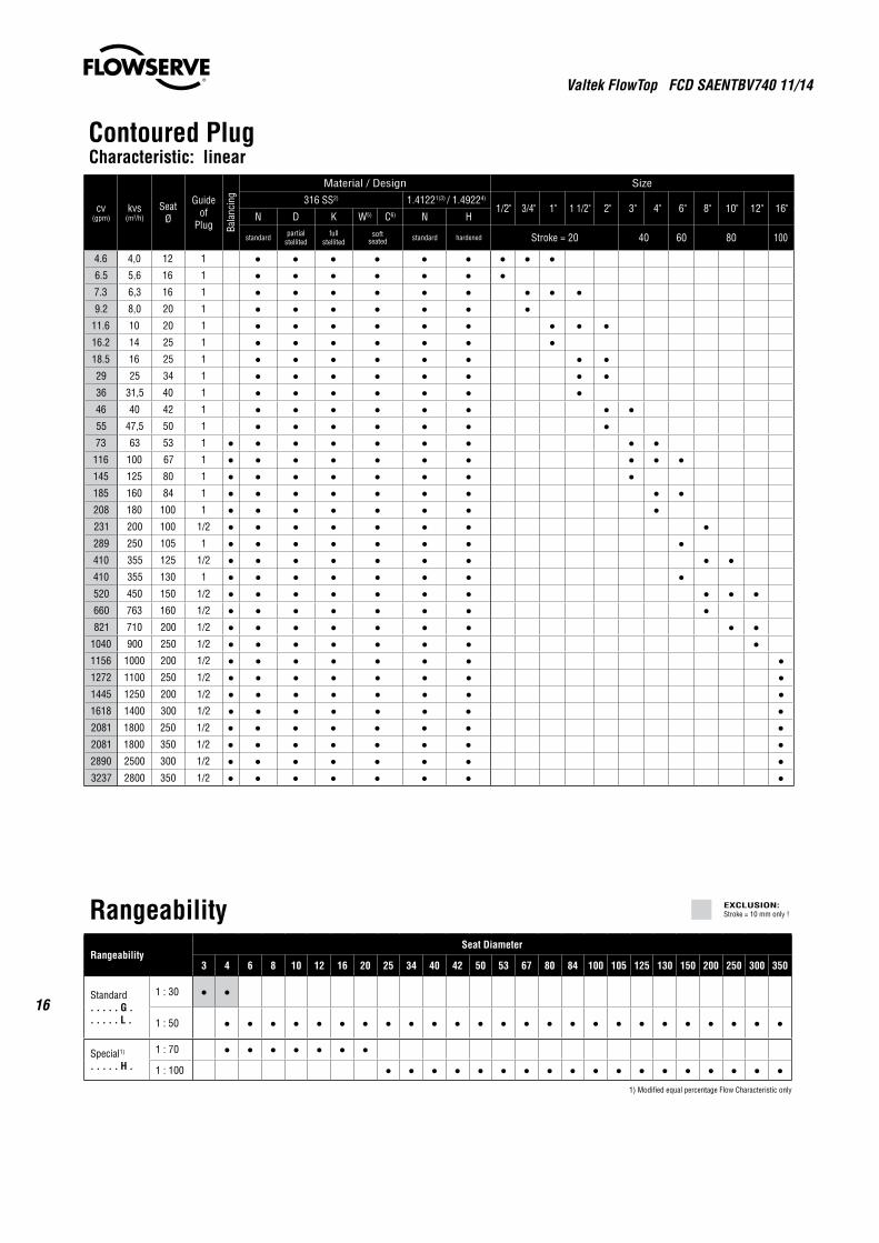
Contoured PlugCharacteristic: linear
cv(gpm)
kvs(m3/h)
SeatØ
Guide of
Plug Bala
ncin
g
Material / Design Size
316 SS2) 1.41221)3) / 1.49224)
1/2" 3/4" 1" 1 1/2" 2" 3" 4" 6" 8" 10" 12" 16"N D K W5) C6) N H
standard partial stellited
full stellited
soft seated standard hardened Stroke = 20 40 60 80 100
4.6 4,0 12 1 6.5 5,6 16 1 7.3 6,3 16 1 9.2 8,0 20 1
11.6 10 20 1 16.2 14 25 1 18.5 16 25 1 29 25 34 1 36 31,5 40 1 46 40 42 1 55 47,5 50 1 73 63 53 1
116 100 67 1 145 125 80 1 185 160 84 1 208 180 100 1 231 200 100 1/2 289 250 105 1 410 355 125 1/2 410 355 130 1 520 450 150 1/2 660 763 160 1/2 821 710 200 1/2
1040 900 250 1/2 1156 1000 200 1/2 1272 1100 250 1/2 1445 1250 200 1/2 1618 1400 300 1/2 2081 1800 250 1/2 2081 1800 350 1/2 2890 2500 300 1/2 3237 2800 350 1/2
RangeabilityRangeability
Seat Diameter
3 4 6 8 10 12 16 20 25 34 40 42 50 53 67 80 84 100 105 125 130 150 200 250 300 350
Standard. . . . . G .. . . . . L .
1 : 30
1 : 50
Special1)
. . . . . H .
1 : 70
1 : 100
1) Modified equal percentage Flow Characteristic only
EXCLUSION:Stroke = 10 mm only !
Valtek FlowTop FCD SAENTBV740 11/14
17
flowserve.com
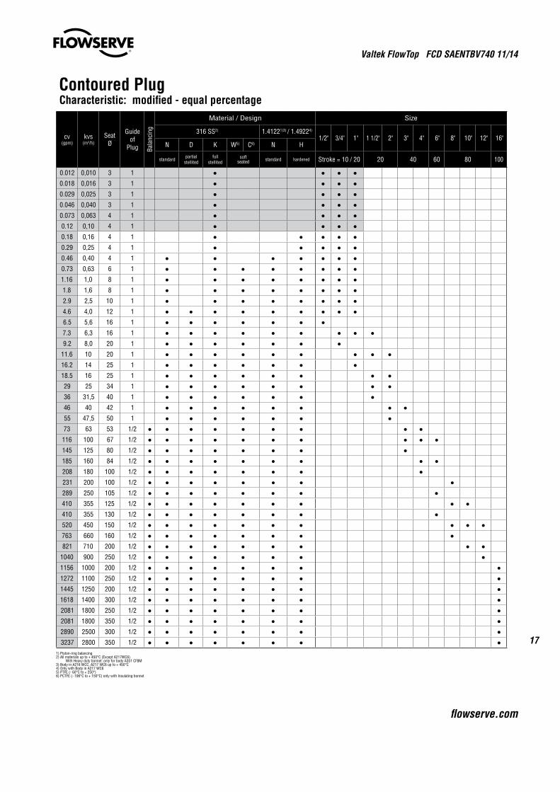
1) Piston-ring balancing2) All materials up to + 450°C (Except A217WC6) With Heavy duty bonnet: only for body A351 CF8M3) Body in A216 WCC, A217 WC6 up to + 450°C4) Only with Body in A217 WC65) PTFE (- 60°C to + 250°)6) PCTFE (- 196°C to + 150°C) only with Insulating bonnet
Contoured PlugCharacteristic: modified - equal percentage
cv(gpm)
kvs(m3/h)
SeatØ
Guide of
Plug Bala
ncin
g
Material / Design Size
316 SS2) 1.41221)3) / 1.49224)
1/2" 3/4" 1" 1 1/2" 2" 3" 4" 6" 8" 10" 12" 16"N D K W5) C6) N H
standard partial stellited
full stellited
soft seated standard hardened Stroke = 10 / 20 20 40 60 80 100
0.012 0,010 3 1 0.018 0,016 3 1 0.029 0,025 3 1 0.046 0,040 3 1 0.073 0,063 4 1 0.12 0,10 4 1 0.18 0,16 4 1 0.29 0,25 4 1 0.46 0,40 4 1 0.73 0,63 6 1 1.16 1,0 8 1 1.8 1,6 8 1 2.9 2,5 10 1 4.6 4,0 12 1 6.5 5,6 16 1 7.3 6,3 16 1 9.2 8,0 20 1
11.6 10 20 1 16.2 14 25 1 18.5 16 25 1 29 25 34 1 36 31,5 40 1 46 40 42 1 55 47,5 50 1 73 63 53 1/2
116 100 67 1/2 145 125 80 1/2 185 160 84 1/2 208 180 100 1/2 231 200 100 1/2 289 250 105 1/2 410 355 125 1/2 410 355 130 1/2 520 450 150 1/2 763 660 160 1/2 821 710 200 1/2
1040 900 250 1/2 1156 1000 200 1/2 1272 1100 250 1/2 1445 1250 200 1/2 1618 1400 300 1/2 2081 1800 250 1/2 2081 1800 350 1/2 2890 2500 300 1/2 3237 2800 350 1/2
Valtek FlowTop FCD SAENTBV740 11/14
18
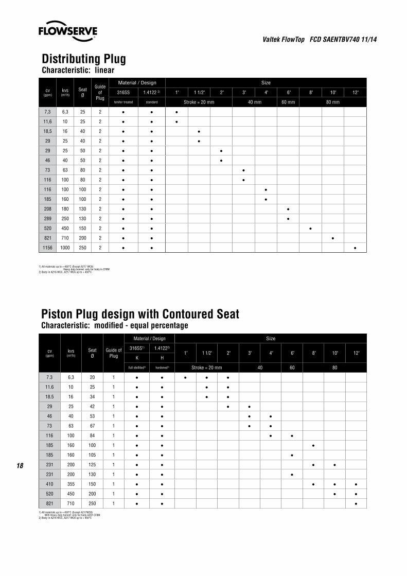
Distributing PlugCharacteristic: linear
cv(gpm)
kvs(m3/h)
SeatØ
Guide of
Plug
Material / Design Size
316SS 1.4122 2) 1" 1 1/2" 2" 3" 4" 6" 8" 10" 12"
tenifer treated standard Stroke = 20 mm 40 mm 60 mm 80 mm
7,3 6,3 25 2
11,6 10 25 2
18,5 16 40 2
29 25 40 2
29 25 50 2
46 40 50 2
73 63 80 2
116 100 80 2
116 100 100 2
185 160 100 2
208 180 130 2
289 250 130 2
520 450 150 2
821 710 200 2
1156 1000 250 2
1) All materials up to + 450°C (Except A217 WC6) Heavy duty bonnet: only for body in CF8M2) Body in A216 WCC, A217 WC6 up to + 450°C
Piston Plug design with Contoured SeatCharacteristic: modified - equal percentage
cv(gpm)
kvs(m3/h)
SeatØ
Guide of Plug
Material / Design Size
316SS1) 1.41222)
1" 1 1/2" 2" 3" 4" 6" 8" 10" 12"K H
full stellited3) hardened3) Stroke = 20 mm 40 60 80
7.3 6,3 20 1
11.6 10 25 1
18.5 16 34 1
29 25 42 1
46 40 53 1
73 63 67 1
116 100 84 1
185 160 100 1
185 160 105 1
231 200 125 1
231 200 130 1
410 355 150 1
520 450 200 1
821 710 250 1
1) All materials up to + 450°C (Except A217WC6) With Heavy duty bonnet: only for body A351 CF8M2) Body in A216 WCC, A217 WC6 up to + 450°C
Valtek FlowTop FCD SAENTBV740 11/14
19
flowserve.com
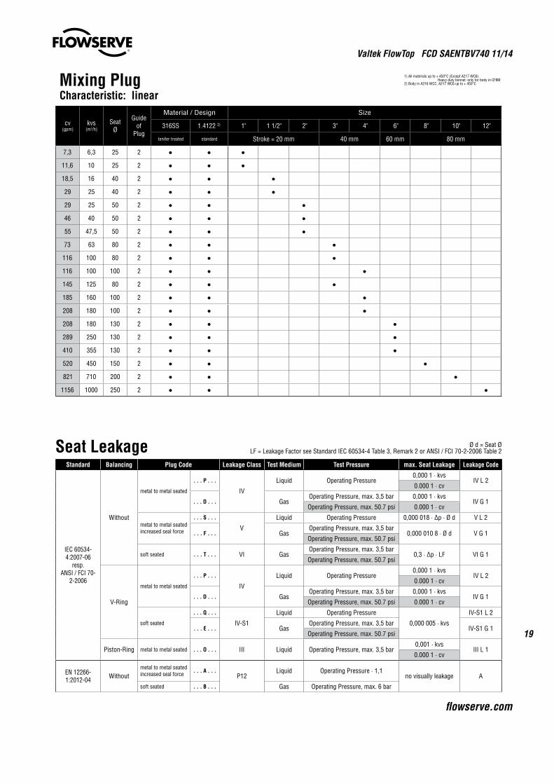
Mixing PlugCharacteristic: linear
cv(gpm)
kvs(m3/h)
SeatØ
Guide of
Plug
Material / Design Size
316SS 1.4122 2) 1" 1 1/2" 2" 3" 4" 6" 8" 10" 12"
tenifer treated standard Stroke = 20 mm 40 mm 60 mm 80 mm
7,3 6,3 25 2
11,6 10 25 2
18,5 16 40 2
29 25 40 2
29 25 50 2
46 40 50 2
55 47,5 50 2
73 63 80 2
116 100 80 2
116 100 100 2
145 125 80 2
185 160 100 2
208 180 100 2
208 180 130 2
289 250 130 2
410 355 130 2
520 450 150 2
821 710 200 2
1156 1000 250 2
1) All materials up to + 450°C (Except A217 WC6) Heavy duty bonnet: only for body in CF8M2) Body in A216 WCC, A217 WC6 up to + 450°C
Seat Leakage Ø d = Seat ØLF = Leakage Factor see Standard IEC 60534-4 Table 3, Remark 2 or ANSI / FCI 70-2-2006 Table 2
Standard Balancing Plug Code Leakage Class Test Medium Test Pressure max. Seat Leakage Leakage Code
IEC 60534-4:2007-06
resp.ANSI / FCI 70-
2-2006
Without
metal to metal seated
. . . P . . .
IV
Liquid Operating Pressure0,000 1 · kvs
IV L 20.000 1 · cv
. . . D . . . GasOperating Pressure, max. 3,5 bar 0,000 1 · kvs
IV G 1Operating Pressure, max. 50.7 psi 0.000 1 · cv
metal to metal seatedincreased seal force
. . . S . . .
V
Liquid Operating Pressure 0,000 018 · ∆p · Ø d V L 2
. . . F . . . GasOperating Pressure, max. 3,5 bar
0,000 010 8 · Ø d V G 1Operating Pressure, max. 50.7 psi
soft seated . . . T . . . VI GasOperating Pressure, max. 3,5 bar
0,3 · ∆p · LF VI G 1Operating Pressure, max. 50.7 psi
V-Ring
metal to metal seated
. . . P . . .
IV
Liquid Operating Pressure0,000 1 · kvs
IV L 20.000 1 · cv
. . . D . . . GasOperating Pressure, max. 3,5 bar 0,000 1 · kvs
IV G 1Operating Pressure, max. 50.7 psi 0.000 1 · cv
soft seated
. . . Q . . .
IV-S1
Liquid Operating Pressure
0,000 005 · kvs
IV-S1 L 2
. . . E . . . GasOperating Pressure, max. 3,5 bar
IV-S1 G 1Operating Pressure, max. 50.7 psi
Piston-Ring metal to metal seated . . . O . . . III Liquid Operating Pressure, max. 3,5 bar0,001 · kvs
III L 10.000 1 · cv
EN 12266-1:2012-04 Without
metal to metal seatedincreased seal force . . . A . . .
P12Liquid Operating Pressure · 1,1
no visually leakage A
soft seated . . . B . . . Gas Operating Pressure, max. 6 bar
Valtek FlowTop FCD SAENTBV740 11/14
20
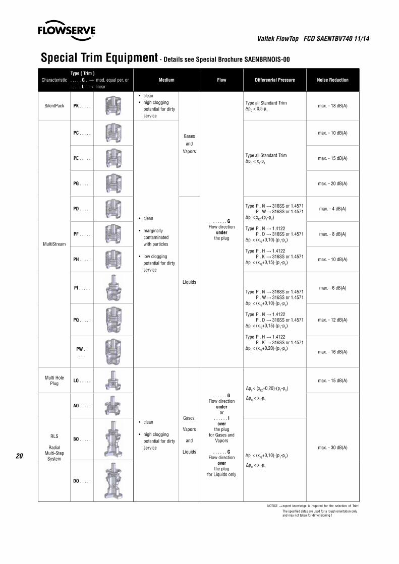
Special Trim Equipment - Details see Special Brochure SAENBRNOIS-00
CharacteristicType ( Trim ). . . . . G . → mod. equal per. or. . . . . L . → linear
Medium Flow Differenrial Pressure Noise Reduction
SilentPack PK . . . . .
• clean • highclogging potential for dirty service
Gases
and
Vapors
. . . . . . GFlow direction
underthe plug
Type all Standard Trim∆pC < 0,5·p1
max. - 18 dB(A)
MultiStream
PC . . . . .
• clean
• marginally contaminated with particles
• lowclogging potential for dirty service
Type all Standard Trim∆pC < xT·p1
max. - 10 dB(A)
PE . . . . . max. - 15 dB(A)
PG . . . . . max. - 20 dB(A)
PD . . . . .
Liquids
Type P . N → 316SS or 1.4571 P . W → 316SS or 1.4571∆pI < xFZ·(p1-pV)
Type P . N → 1.4122 P . D → 316SS or 1.4571∆pI < (xFZ+0,10)·(p1-pV)
Type P . H → 1.4122 P . K → 316SS or 1.4571∆pI < (xFZ+0,15)·(p1-pV)
max. - 4 dB(A)
PF . . . . . max. - 8 dB(A)
PH . . . . . max. - 10 dB(A)
PI . . . . .Type P . N → 316SS or 1.4571 P . W → 316SS or 1.4571∆pI < (xFZ+0,10)·(p1-pV)
Type P . N → 1.4122 P . D → 316SS or 1.4571∆pI < (xFZ+0,15)·(p1-pV)
Type P . H → 1.4122 P . K → 316SS or 1.4571∆pI < (xFZ+0,20)·(p1-pV)
max. - 6 dB(A)
PQ . . . . . max. - 12 dB(A)
PW . . . . . max. - 16 dB(A)
Multi Hole Plug LO . . . . .
• clean
• highclogging potential for dirty service
Gases,
Vapors
and
Liquids
. . . . . . GFlow direction
underor
. . . . . . Iover
the plugfor Gases and
Vapors
. . . . . . GFlow direction
overthe plug
for Liquids only
∆pI < (xFZ+0,20)·(p1-pV)
∆pC < xT·p1
max. - 15 dB(A)
RLS
RadialMulti-Step
System
AO . . . . .
max. - 30 dB(A)
BO . . . . .
∆pI < (xFZ+0,10)·(p1-pV)
∆pC < xT·p1
DO . . . . .
NOTICE → expert knowledge is required for the selection of Trim!
The specified datas are used for a rough orientation only and may not taken for dimensioning !
Valtek FlowTop FCD SAENTBV740 11/14
21
flowserve.com
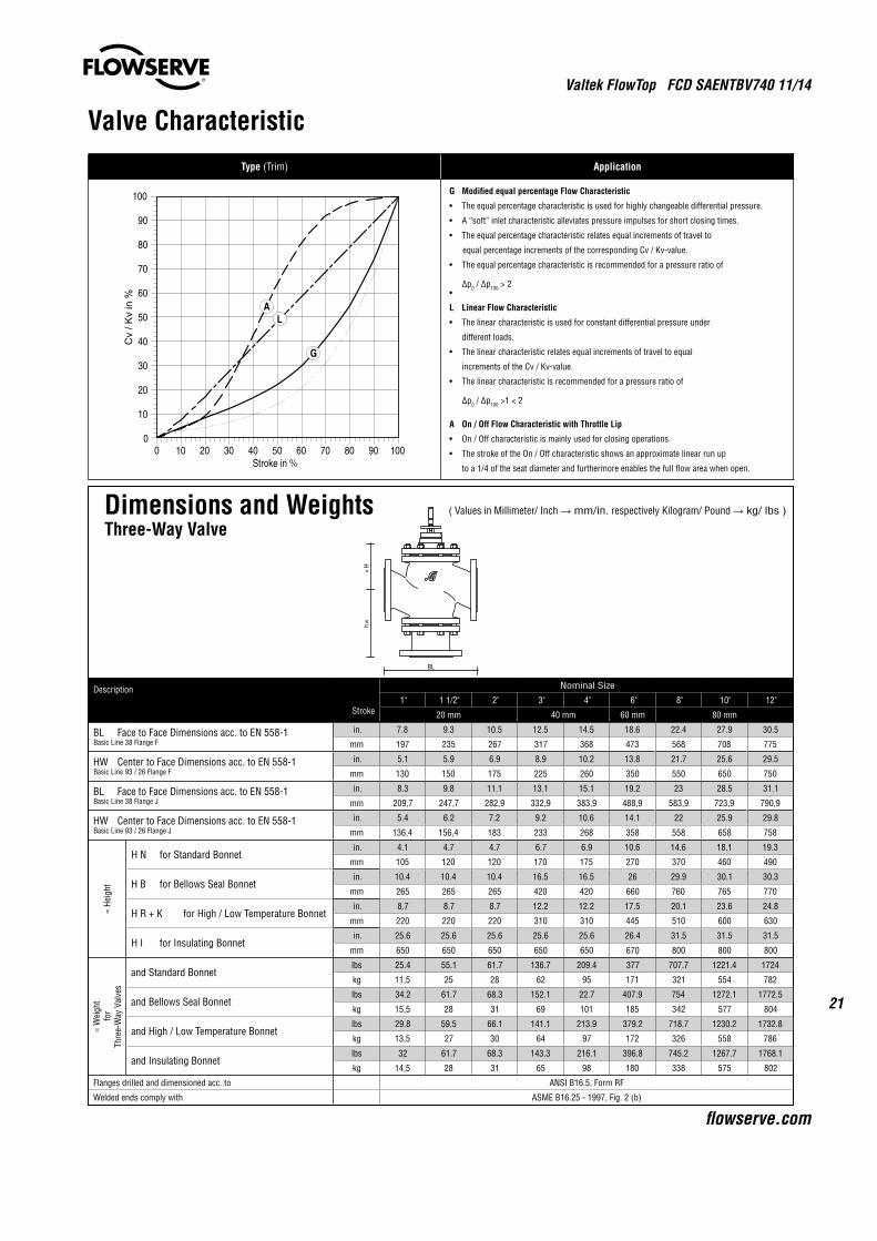
Valve CharacteristicType (Trim) Application
G Modified equal percentage Flow Characteristic
• Theequalpercentagecharacteristicisusedforhighlychangeabledifferentialpressure.
• A“soft” inlet characteristic alleviates pressure impulses for short closing times.
• Theequalpercentagecharacteristicrelatesequalincrementsoftravelto
equal percentage increments of the corresponding Cv / Kv-value.
• Theequalpercentagecharacteristicisrecommendedforapressureratioof
∆p0 / ∆p100 > 2•
L Linear Flow Characteristic
• Thelinearcharacteristicisusedforconstantdifferentialpressureunder
different loads.
• Thelinearcharacteristicrelatesequalincrementsoftraveltoequal
increments of the Cv / Kv-value.
• Thelinearcharacteristicisrecommendedforapressureratioof
∆p0 / ∆p100 >1 < 2
A On / Off Flow Characteristic with Throttle Lip
• On/Offcharacteristicismainlyusedforclosingoperations.
• ThestrokeoftheOn/Offcharacteristicshowsanapproximatelinearrunup
to a 1/4 of the seat diameter and furthermore enables the full flow area when open.
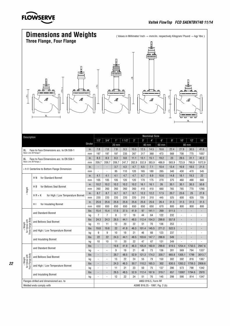
Description
Stroke
Nominal Size
1" 1 1/2" 2" 3" 4" 6" 8" 10" 12"
20 mm 40 mm 60 mm 80 mm
BL Face to Face Dimensions acc. to EN 558-1 Basic Line 38 Flange F
in. 7.8 9.3 10.5 12.5 14.5 18.6 22.4 27.9 30.5
mm 197 235 267 317 368 473 568 708 775
HW Center to Face Dimensions acc. to EN 558-1 Basic Line 93 / 26 Flange F
in. 5.1 5.9 6.9 8.9 10.2 13.8 21.7 25.6 29.5
mm 130 150 175 225 260 350 550 650 750
BL Face to Face Dimensions acc. to EN 558-1 Basic Line 38 Flange J
in. 8.3 9.8 11.1 13.1 15.1 19.2 23 28.5 31.1
mm 209,7 247,7 282,9 332,9 383,9 488,9 583,9 723,9 790,9
HW Center to Face Dimensions acc. to EN 558-1 Basic Line 93 / 26 Flange J
in. 5.4 6.2 7.2 9.2 10.6 14.1 22 25.9 29.8
mm 136,4 156,4 183 233 268 358 558 658 758
≈ He
ight
H N for Standard Bonnetin. 4.1 4.7 4.7 6.7 6.9 10.6 14.6 18.1 19.3
mm 105 120 120 170 175 270 370 460 490
H B for Bellows Seal Bonnetin. 10.4 10.4 10.4 16.5 16.5 26 29.9 30.1 30.3
mm 265 265 265 420 420 660 760 765 770
H R + K for High / Low Temperature Bonnetin. 8.7 8.7 8.7 12.2 12.2 17.5 20.1 23.6 24.8
mm 220 220 220 310 310 445 510 600 630
H I for Insulating Bonnetin. 25.6 25.6 25.6 25.6 25.6 26.4 31.5 31.5 31.5
mm 650 650 650 650 650 670 800 800 800
≈ W
eigh
t fo
rTh
ree-
Way
Val
ves
and Standard Bonnetlbs 25.4 55.1 61.7 136.7 209.4 377 707.7 1221.4 1724
kg 11,5 25 28 62 95 171 321 554 782
and Bellows Seal Bonnetlbs 34.2 61.7 68.3 152.1 22.7 407.9 754 1272.1 1772.5
kg 15,5 28 31 69 101 185 342 577 804
and High / Low Temperature Bonnetlbs 29.8 59.5 66.1 141.1 213.9 379.2 718.7 1230.2 1732.8
kg 13,5 27 30 64 97 172 326 558 786
and Insulating Bonnetlbs 32 61.7 68.3 143.3 216.1 396.8 745.2 1267.7 1768.1
kg 14,5 28 31 65 98 180 338 575 802
Flanges drilled and dimensioned acc. to ANSI B16.5, Form RF
Welded ends comply with ASME B16.25 - 1997, Fig. 2 (b)
Dimensions and Weights ( Values in Millimeter/ Inch → mm/in. respectively Kilogram/ Pound → kg/ lbs )
Three-Way Valve
Valtek FlowTop FCD SAENTBV740 11/14
22
Description
Stroke
Nominal Size
1/2" 3/4" 1" 1 1/2" 2" 3" 4" 6" 8" 10" 12" 16"
20 mm 40 mm 60 mm 80 mm
BL Face to Face Dimensions acc. to EN 558-1 Basic Line 38 Flange F
in. 7.8 7.8 7.8 9.3 10.5 12.5 14.5 18.6 22.4 27.9 30.5 41.6
mm 197 197 197 235 267 317 368 473 568 708 775 1057
BL Face to Face Dimensions acc. to EN 558-1 Basic Line 38 Flange J
in. 8.3 8.3 8.3 9.8 11.1 13.1 15.1 19.2 23 28.5 31.1 42.2
mm 209,7 209,7 209,7 247,7 282,9 332,9 383,9 488,9 583,9 723,9 790,9 1072,9
≈ h V Centerline to Bottom Flange Dimensionin. - - 3.7 4.3 4.7 6.5 7.1 10.4 13.4 16.9 18.5 21.5
mm - - 95 110 120 165 180 265 340 430 470 545
≈ He
ight
H N for Standard Bonnetin. 4.1 4.1 4.1 4.7 4.7 6.7 6.9 10.6 14.8 18.1 19.3 22
mm 105 105 105 120 120 170 175 270 375 460 490 560
H B for Bellows Seal Bonnetin. 10.2 10.2 10.2 10.2 10.2 16.1 16.1 26 30.1 30.1 30.3 50.8
mm 260 260 260 260 260 410 410 660 765 765 770 1290
H R + K for High / Low Temperature Bonnetin. 8.7 8.7 8.7 8.7 8.7 12.2 12.2 17.5 20.7 23.6 25 27.8
mm 220 220 220 220 220 310 310 445 525 600 635 705
H I for Insulating Bonnetin. 25.6 25.6 25.6 25.6 25.6 25.6 25.6 26.4 31.5 31.5 31.5 31.5
mm 650 650 650 650 650 650 650 670 800 800 800 800
≈ W
eigh
t fo
r Val
ves
with
Thre
e-Fl
ange
Bod
y
and Standard-Bonnetlbs 15.4 15.4 17.6 37.5 41.9 97 141.1 269 511.5 - - -
kg 7 7 8 17 19 44 64 122 232 - - -
and Bellows Seal Bonnetlbs 24.3 24.3 26.5 44.1 48.5 112.4 154.3 299.8 557.8 - - -
kg 11 11 12 20 22 51 70 136 253 - - -
and High / Low Temperature Bonnetlbs 19.8 19.8 22 41.9 46.3 101.4 145.5 271.2 522.5 - - -
kg 9 9 10 19 21 46 66 123 237 - - -
and Insulating Bonnetlbs 22 22 24.3 44.1 48.5 103.6 147.7 288.8 549 - - -
kg 10 10 11 20 22 47 67 131 249 - - -
≈ W
eigh
t fo
r Val
ves
with
Four
-Fla
nge
Body
and Standard Bonnetlbs - - 19.8 41.9 46.3 105.8 160.9 299.8 619.5 1254.4 1750.5 2947.6
kg - - 9 19 21 48 73 136 281 569 794 1337
and Bellows Seal Bonnetlbs - - 28.7 48.5 52.9 121.3 174.2 330.7 665.8 1305.1 1799 3013.7
kg - - 13 22 24 55 79 150 302 592 816 1367
and High / Low Temperature Bonnetlbs - - 24.3 46.3 50.7 110.2 165.3 302 630.5 1263.2 1759.3 2958.6
kg - - 11 21 23 50 75 137 286 573 798 1342
and Insulating Bonnetlbs - - 26.5 48.5 52.9 112.4 167.6 319.7 657 13007 1794.6 2970
kg - - 12 22 24 51 76 145 298 590 814 1347
Flanges drilled and dimensioned acc. to ANSI B16.5, Form RF
Welded ends comply with ASME B16.25 - 1997, Fig. 2 (b)
Dimensions and Weights ( Values in Millimeter/ Inch → mm/in. respectively Kilogram/ Pound → kg/ lbs )
Three Flange, Four Flange
Valtek FlowTop FCD SAENTBV740 11/14
23
flowserve.com
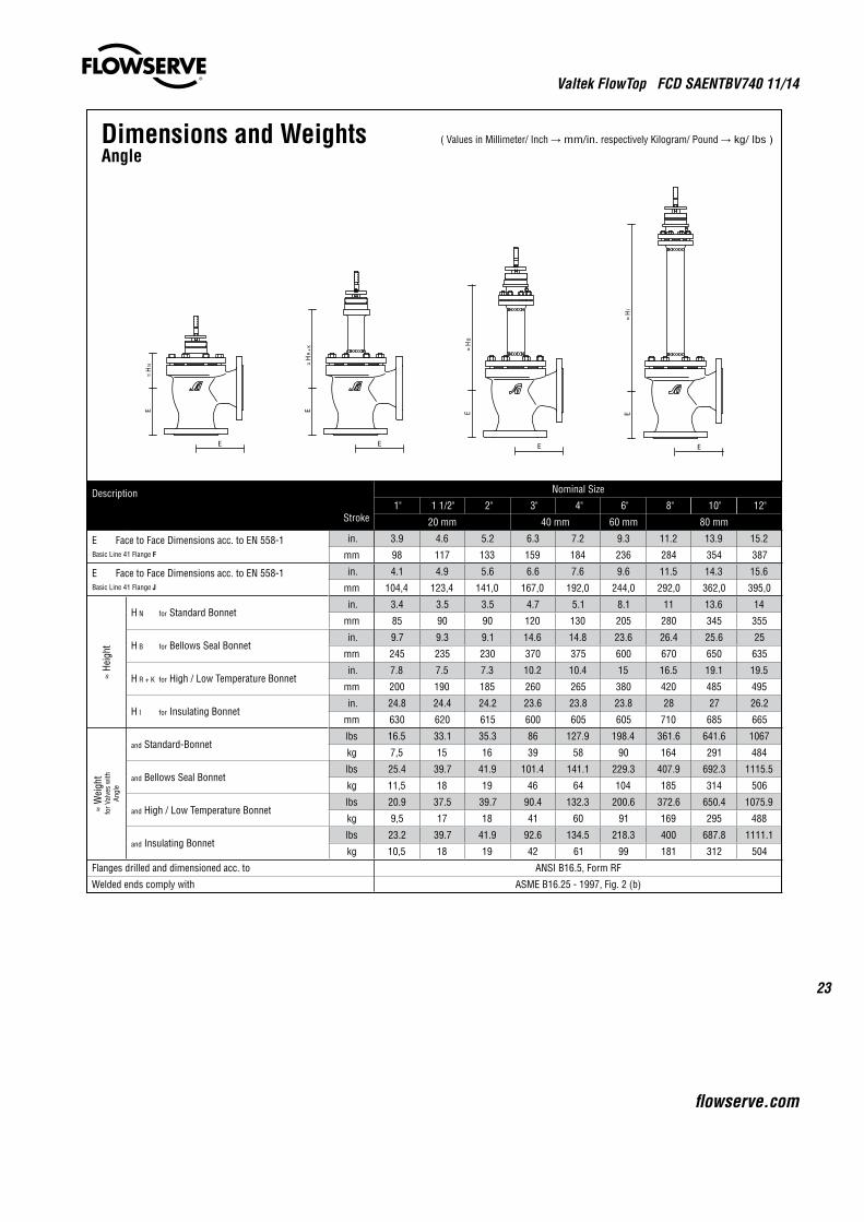
Description
Stroke
Nominal Size
1" 1 1/2" 2" 3" 4" 6" 8" 10" 12"
20 mm 40 mm 60 mm 80 mm
E Face to Face Dimensions acc. to EN 558-1 Basic Line 41 Flange F
in. 3.9 4.6 5.2 6.3 7.2 9.3 11.2 13.9 15.2
mm 98 117 133 159 184 236 284 354 387
E Face to Face Dimensions acc. to EN 558-1 Basic Line 41 Flange J
in. 4.1 4.9 5.6 6.6 7.6 9.6 11.5 14.3 15.6
mm 104,4 123,4 141,0 167,0 192,0 244,0 292,0 362,0 395,0
≈ He
ight
H N for Standard Bonnetin. 3.4 3.5 3.5 4.7 5.1 8.1 11 13.6 14
mm 85 90 90 120 130 205 280 345 355
H B for Bellows Seal Bonnetin. 9.7 9.3 9.1 14.6 14.8 23.6 26.4 25.6 25
mm 245 235 230 370 375 600 670 650 635
H R + K for High / Low Temperature Bonnetin. 7.8 7.5 7.3 10.2 10.4 15 16.5 19.1 19.5
mm 200 190 185 260 265 380 420 485 495
H I for Insulating Bonnetin. 24.8 24.4 24.2 23.6 23.8 23.8 28 27 26.2
mm 630 620 615 600 605 605 710 685 665
≈ W
eigh
t fo
r Val
ves
with
Angl
e
and Standard-Bonnetlbs 16.5 33.1 35.3 86 127.9 198.4 361.6 641.6 1067
kg 7,5 15 16 39 58 90 164 291 484
and Bellows Seal Bonnetlbs 25.4 39.7 41.9 101.4 141.1 229.3 407.9 692.3 1115.5
kg 11,5 18 19 46 64 104 185 314 506
and High / Low Temperature Bonnetlbs 20.9 37.5 39.7 90.4 132.3 200.6 372.6 650.4 1075.9
kg 9,5 17 18 41 60 91 169 295 488
and Insulating Bonnetlbs 23.2 39.7 41.9 92.6 134.5 218.3 400 687.8 1111.1
kg 10,5 18 19 42 61 99 181 312 504
Flanges drilled and dimensioned acc. to ANSI B16.5, Form RF
Welded ends comply with ASME B16.25 - 1997, Fig. 2 (b)
Dimensions and Weights ( Values in Millimeter/ Inch → mm/in. respectively Kilogram/ Pound → kg/ lbs )
Angle

Valtek FlowTop FCD SAENTBV740 11/14
24
Description
Stroke
Nominal Size
1" 1 1/2" 2" 3" 4" 6" 8" 10" 12" 16"
20 mm 40 mm 60 mm 80 mm
BL Face to Face Dimensions acc. to EN 558-1 Basic Line 38 Flange F
in. 7.8 9.3 10.5 12.5 14.5 18.6 22.4 27.9 30.5 41.6
mm 197 235 267 317 368 473 568 708 775 1057
BL Face to Face Dimensions acc. to EN 558-1 Basic Line 38 Flange J
in. 8.3 9.8 11.1 13.1 15.1 19.2 23 28.5 31.1 42.2
mm 209,7 247,7 282,9 332,9 383,9 488,9 583,9 723,9 790,9 1072,9
E Face to Face Dimensions acc. to EN 558-1 Basic Line 41 Flange F
in. 3.9 4.6 5.2 6.3 7.2 9.3 11.2 13.9 15.2 -
mm 98 117 133 159 184 236 284 354 387 -
E Face to Face Dimensions acc. to EN 558-1 Basic Line 41 Flange J
in. 4.1 4.9 5.6 6.6 7.6 9.6 11.5 14.3 15.6 -
mm 104,4 123,4 141,0 167,0 192,0 244,0 292,0 362,0 395,0 -
≈ h V Centerline to Bottom Flange Dimensionin. 3.9 4.7 4.9 7.1 7.9 11.2 13.6 16.9 18.5 21.5
mm 100 120 125 180 200 285 345 430 470 545
h W Centerline to Flange Tube Dimensionin. 5.12 5.91 6.89 8.86 10.24 13.78 21.65 25.59 29.53 -
mm 130 150 175 225 260 350 550 650 750 -
≈ H S for Standard Bonnet „Heavy Duty Design“in. 10.2 10.6 10.8 17.3 18.1 23 31.5 35 36.6 39.4
mm 260 270 275 440 460 585 800 890 930 1000
≈ H S for Standard Bonnet „Heavy Duty Design“ - Angel
in. 9.5 9.5 9.5 15.4 16.3 20.5 28 30.5 31.3 -
mm 240 240 240 390 415 520 710 775 795 -
≈ W
eigh
t (kg
)
Three Flange Valve and Standard-Bonnet „HDD“
lbs 30.9 48.5 52.9 134.5 187.4 317.5 703.3 - - -
kg 14 22 24 61 85 144 319 - - -
Four Flange Valve and Standard-Bonnet „HDD“
lbs 33.1 48.5 59.5 145.5 191.8 361.6 811.3 1485.9 1975.3 3254
kg 15 22 27 66 87 164 368 674 896 1476
Three-Way Valve and Standard-Bonnet „HDD“lbs 38.6 66.1 72.8 174.2 255.7 425.5 899.5 1452.9 1948.9 -
kg 17,5 30 33 79 116 193 408 659 884 -
Angel and Standard-Bonnet „HDD“
lbs 29,8 44.1 46.3 123.5 174.2 246.9 553.4 873 1291.9 -
kg 13,5 20 21 56 79 112 251 396 586 -
Flanges drilled and dimensioned acc. to ANSI B16.5, Form RF
Welded ends comply with ASME B16.25 - 1997, Fig. 2 (b)
Dimensions and Weights ( Values in Millimeter/ Inch → mm/in. respectively Kilogram/ Pound → kg/ lbs )
Three Flange, Four Flange, Three-Way Valve with „Heavy Duty“ Bonnet only
Valtek FlowTop FCD SAENTBV740 11/14
25
flowserve.com
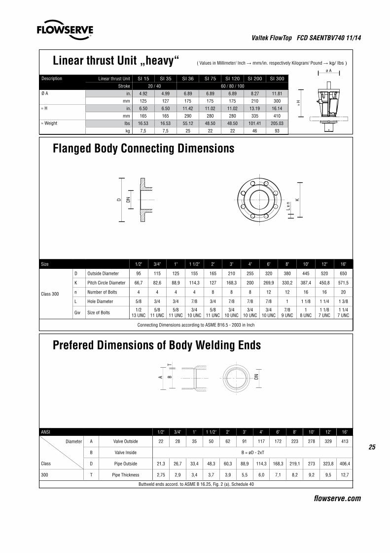
Flanged Body Connecting Dimensions
Size 1/2" 3/4" 1" 1 1/2" 2" 3" 4" 6" 8" 10" 12" 16"
Class 300
D Outside Diameter 95 115 125 155 165 210 255 320 380 445 520 650
K Pitch Circle Diameter 66,7 82,6 88,9 114,3 127 168,3 200 269,9 330,2 387,4 450,8 571,5
n Number of Bolts 4 4 4 4 8 8 8 12 12 16 16 20
L Hole Diameter 5/8 3/4 3/4 7/8 3/4 7/8 7/8 7/8 1 1 1/8 1 1/4 1 3/8
Gw Size of Bolts 1/213 UNC
5/811 UNC
5/811 UNC
3/410 UNC
5/811 UNC
3/410 UNC
3/410 UNC
3/410 UNC
7/89 UNC
18 UNC
1 1/87 UNC
1 1/47 UNC
Connecting Dimensions according to ASME B16.5 - 2003 in Inch
ANSI 1/2" 3/4" 1" 1 1/2" 2" 3" 4" 6" 8" 10" 12" 16"
Diameter
Class
A Valve Outside 22 28 35 50 62 91 117 172 223 278 329 413
B Valve Inside B = øD - 2xT
D Pipe Outside 21,3 26,7 33,4 48,3 60,3 88,9 114,3 168,3 219,1 273 323,8 406,4
300 T Pipe Thickness 2,75 2,9 3,4 3,7 3,9 5,5 6,0 7,1 8,2 9,2 9,5 12,7
Buttweld ends accord. to ASME B 16.25, Fig. 2 (a), Schedule 40
Prefered Dimensions of Body Welding Ends
DN
T
A B
Description Linear thrust Unit SI 15 SI 35 SI 36 SI 75 SI 120 SI 200 SI 300
Stroke 20 / 40 60 / 80 / 100
Ø A in. 4.92 4.99 6.89 6.89 6.89 8.27 11.81
mm 125 127 175 175 175 210 300
≈ H in. 6.50 6.50 11.42 11.02 11.02 13.19 16.14
mm 165 165 290 280 280 335 410
≈ Weight lbs 16.53 16.53 55.12 48.50 48.50 101.41 205.03
kg 7,5 7,5 25 22 22 46 93
Linear thrust Unit „heavy“ ( Values in Millimeter/ Inch → mm/in. respectively Kilogram/ Pound → kg/ lbs )
Valtek FlowTop FCD SAENTBV740 11/14
26
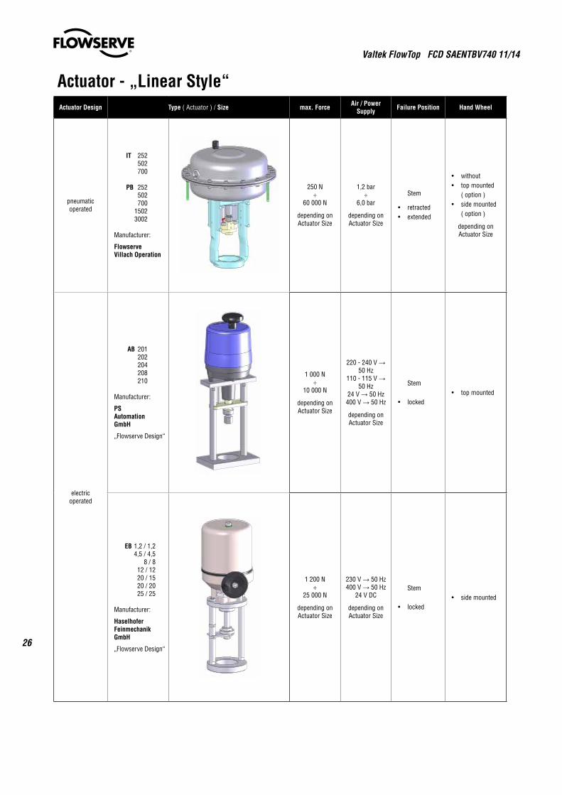
Actuator - „Linear Style“Actuator Design Type ( Actuator ) / Size max. Force Air / Power
Supply Failure Position Hand Wheel
pneumaticoperated
IT 252 502 700
PB 252 502 700 1502 3002
Manufacturer:
Flowserve Villach Operation
250 N÷
60 000 N
depending onActuator Size
1,2 bar÷
6,0 bar
depending onActuator Size
Stem
• retracted • extended
• without • topmounted ( option ) • sidemounted ( option )
depending onActuator Size
electricoperated
AB 201 202 204 208 210
Manufacturer:
PS Automation GmbH
„Flowserve Design“
1 000 N÷
10 000 N
depending onActuator Size
220 - 240 V → 50 Hz
110 - 115 V → 50 Hz
24 V → 50 Hz400 V → 50 Hz
depending onActuator Size
Stem
• locked • topmounted
EB 1,2 / 1,2 4,5 / 4,5 8 / 8 12 / 12 20 / 15 20 / 20 25 / 25
Manufacturer:
Haselhofer Feinmechanik GmbH
„Flowserve Design“
1 200 N÷
25 000 N
depending onActuator Size
230 V → 50 Hz400 V → 50 Hz
24 V DC
depending onActuator Size
Stem
• locked • sidemounted

Valtek FlowTop FCD SAENTBV740 11/14
27
flowserve.com
Actuator - „Linear Style“Actuator Design Type / Size max. Force Power Supply Failure Position Hand Wheel
handoperated
HB 12 16 20
Manufacturer:
Flowserve Villach Operation
13 00 N÷
30 000 N
depending onActuator Size
bi-manualHand operating
Force
200 N
Stem
• locked • topmounted
Actuator - „Multi Turn Style“Actuator Design Type max. Force max. Torque Actuator
Interface Actuator
Linear thrust Unit „light“
linked to anelectric multi turn
actuator
LB 12 16 20
Manufacturer:
Flowserve Villach Operation
10 400 N÷
27 700 N
depending onLinear thrust Unit
Size
30 Nm÷
80 Nm
depending onLinear thrust Unit
Size
Output driveISO 5210 A
Connection Flange ISO 5210 F10
adapted for electrical multi turn actuatorswith output drivesversion „stem nut“
with trapezoid thread 24 x 5 left
Linear thrust Unit „heavy“
only linked to thebonnet SN
and anelectric multi turn
actuator
SI 15 35 36 75 120 200 300
Manufacturer:
Flowserve Villach Operation
15 000 N÷
288 000 N
depending onLinear thrust Unit
Size
30 Nm÷
1700 Nm
depending onLinear thrust Unit
Size
Output driveISO 5210 B3
Connection Flange ISO 5210 F10 F14 F16 F25
depending onLinear thrust Unit
Size
adapted for electrical multi turn actuatorswith output drives version „bore“ with
keyway
Valtek FlowTop FCD SAENTBV740 11/14
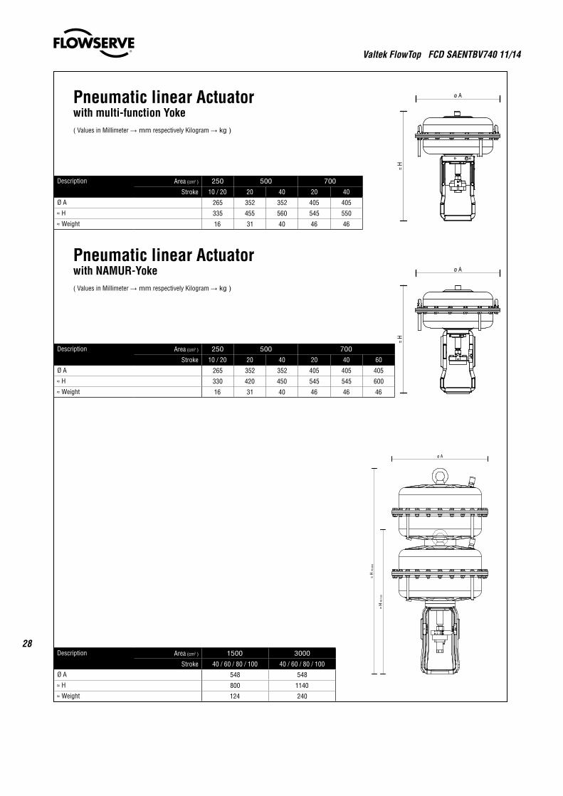
28Description Area (cm2 ) 1500 3000
Stroke 40 / 60 / 80 / 100 40 / 60 / 80 / 100
Ø A 548 548
≈ H 800 1140
≈ Weight 124 240
Description Area (cm2 ) 250 500 700
Stroke 10 / 20 20 40 20 40 60
Ø A 265 352 352 405 405 405
≈ H 330 420 450 545 545 600
≈ Weight 16 31 40 46 46 46
Pneumatic linear Actuatorwith NAMUR-Yoke( Values in Millimeter → mm respectively Kilogram → kg )
Description Area (cm2 ) 250 500 700
Stroke 10 / 20 20 40 20 40
Ø A 265 352 352 405 405
≈ H 335 455 560 545 550
≈ Weight 16 31 40 46 46
Pneumatic linear Actuatorwith multi-function Yoke( Values in Millimeter → mm respectively Kilogram → kg )
Valtek FlowTop FCD SAENTBV740 11/14
29
flowserve.com
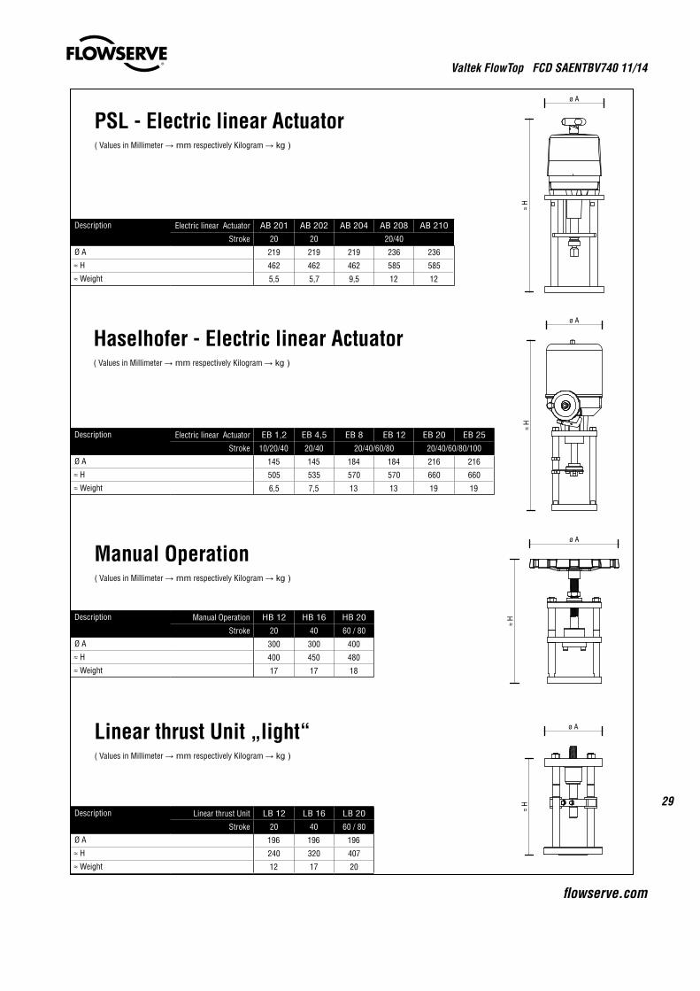
Linear thrust Unit „light“( Values in Millimeter → mm respectively Kilogram → kg )
Description Linear thrust Unit LB 12 LB 16 LB 20
Stroke 20 40 60 / 80
Ø A 196 196 196
≈ H 240 320 407
≈ Weight 12 17 20
Manual Operation( Values in Millimeter → mm respectively Kilogram → kg )
Description Manual Operation HB 12 HB 16 HB 20
Stroke 20 40 60 / 80
Ø A 300 300 400
≈ H 400 450 480
≈ Weight 17 17 18
Description Electric linear Actuator AB 201 AB 202 AB 204 AB 208 AB 210
Stroke 20 20 20/40
Ø A 219 219 219 236 236
≈ H 462 462 462 585 585
≈ Weight 5,5 5,7 9,5 12 12
PSL - Electric linear Actuator( Values in Millimeter → mm respectively Kilogram → kg )
Haselhofer - Electric linear Actuator( Values in Millimeter → mm respectively Kilogram → kg )
Description Electric linear Actuator EB 1,2 EB 4,5 EB 8 EB 12 EB 20 EB 25
Stroke 10/20/40 20/40 20/40/60/80 20/40/60/80/100
Ø A 145 145 184 184 216 216
≈ H 505 535 570 570 660 660
≈ Weight 6,5 7,5 13 13 19 19
Valtek FlowTop FCD SAENTBV740 11/14
30
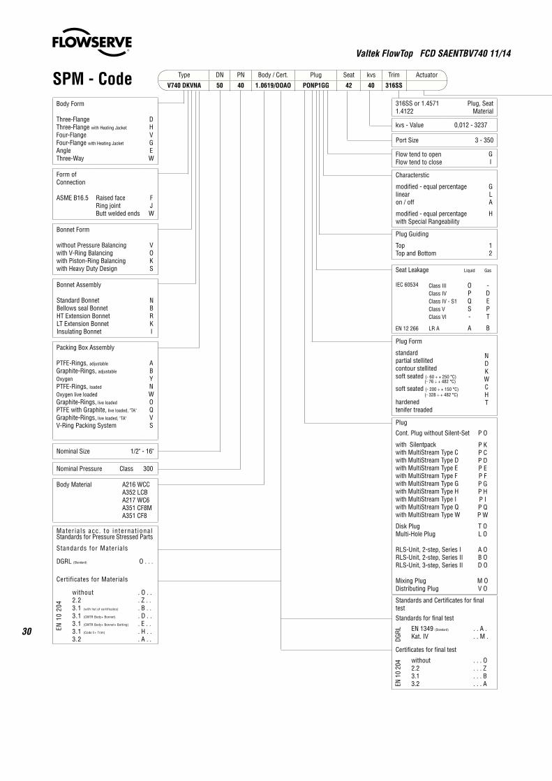
Type DN PN Body / Cert. Plug Seat kvs Trim Actuator
V740 DKVNA 50 40 1.0619/OOAO PONP1GG 42 40 316SS
Body Form
Three-FlangeThree-Flange with Heating Jacket
Four-FlangeFour-Flange with Heating Jacket
AngleThree-Way
DHVGEW
Form of Connection
ASME B16.5 Raised faceRing jointButt welded ends
FJW
Bonnet Form
without Pressure Balancingwith V-Ring Balancingwith Piston-Ring Balancingwith Heavy Duty Design
VOKS
Bonnet Assembly
Standard BonnetBellows seal BonnetHT Extension BonnetLT Extension BonnetInsulating Bonnet
NBRKI
Packing Box Assembly
PTFE-Rings, adjustable
Graphite-Rings, adjustable
OxygenPTFE-Rings, loaded
Oxygen live loadedGraphite-Rings, live loaded
PTFE with Graphite, live loaded, "TA"
Graphite-Rings, live loaded, "TA"
V-Ring Packing System
ABYNWOQVS
Nominal Size 1/2" - 16"
Nominal Pressure Class 300
Body Material A216 WCCA352 LCBA217 WC6A351 CF8MA351 CF8
Mater ia ls acc . to in ternat iona lStandards for Pressure Stressed Parts
Standards for Materials
DGRL (Standard) O . . .
Certificates for Materials
EN 1
0 20
4
without2.23.1 (with list of certificates)
3.1 (CMTR Body+ Bonnet)
3.1 (CMTR Body+ Bonnet+ Bolting)
3.1 (Code E+ Trim)
3.2
. O . .
. Z . .
. B . .
. D . .
. E . .
. H . .
. A . .
SPM - Code
Plug Form
standardpartial stellitedcontour stellitedsoft seated (- 60 ÷ + 250 °C) (- 76 ÷ + 482 °C)
soft seated (- 200 ÷ + 150 °C) (- 328 ÷ + 482 °C)
hardenedtenifer treaded
NDKWCHT
Characterstic
modified - equal percentagelinearon / off
modified - equal percentagewith Special Rangeability
GLA
H
316SS or 1.45711.4122
Plug, Seat Material
kvs - Value 0,012 - 3237
Port Size 3 - 350
Flow tend to openFlow tend to close
GI
Plug Guiding
TopTop and Bottom
12
Seat Leakage
IEC 60534
EN 12 266
Class IIIClass IVClass IV - S1Class VClass VI
LR A
Liquid
OPQS-
A
Gas
-DEPT
B
Plug
Cont. Plug without Silent-Set P O
with Silentpackwith MultiStream Type Cwith MultiStream Type Dwith MultiStream Type Ewith MultiStream Type Fwith MultiStream Type Gwith MultiStream Type Hwith MultiStream Type Iwith MultiStream Type Qwith MultiStream Type W
P KP CP DP EP FP GP HP IP QP W
Disk PlugMulti-Hole Plug
RLS-Unit, 2-step, Series IRLS-Unit, 2-step, Series IIRLS-Unit, 3-step, Series II
Mixing PlugDistributing Plug
T OL O
A OB OD O
M OV O
Standards and Certificates for final testStandards for final test
DGRL EN 1349 (Standard)
Kat. IV. . A .. . M .
Certificates for final test
EN 1
0 20
4 without2.23.13.2
. . . O
. . . Z
. . . B
. . . A
Valtek FlowTop FCD SAENTBV740 11/14
31
flowserve.com
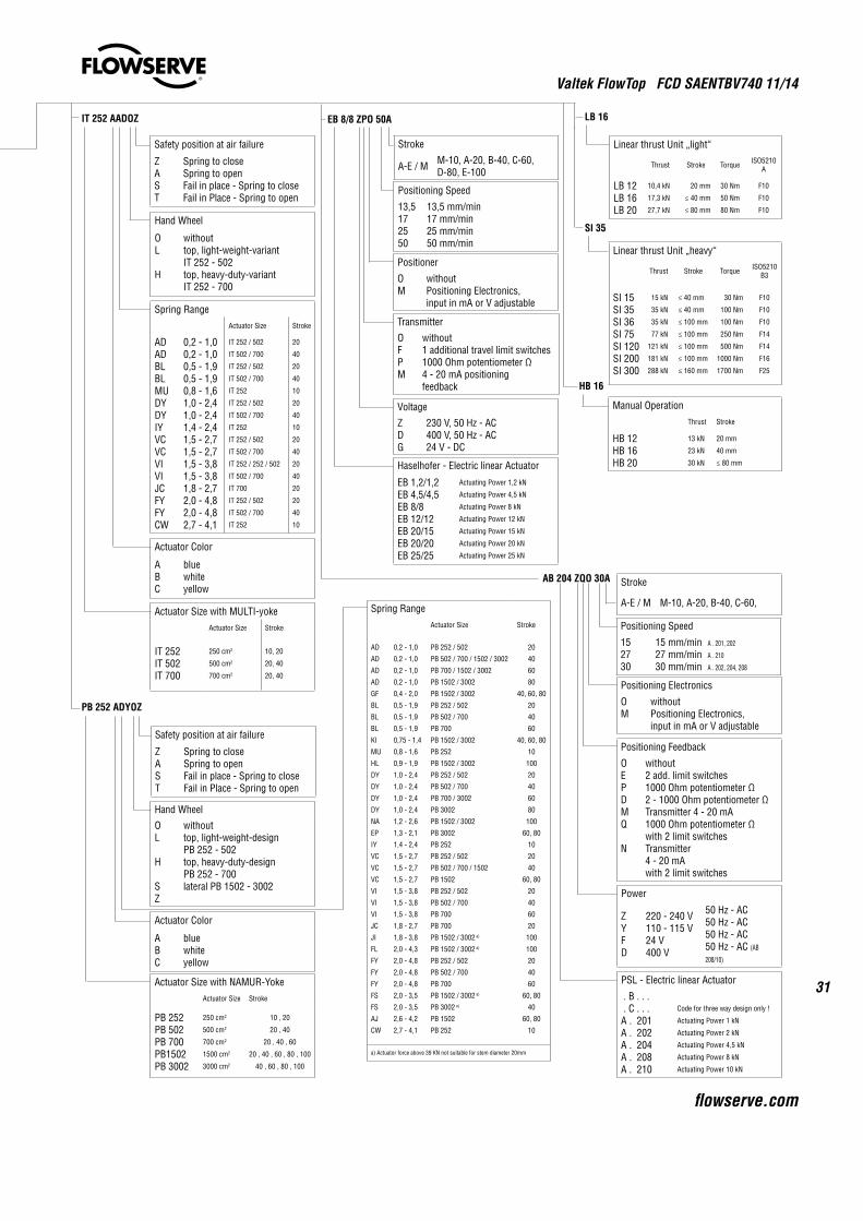
IT 252 AADOZ
Safety position at air failure
ZAST
Spring to closeSpring to openFail in place - Spring to closeFail in Place - Spring to open
Hand Wheel
OL
H
withouttop, light-weight-variant IT 252 - 502top, heavy-duty-variantIT 252 - 700
Spring RangeActuator Size Stroke
ADADBLBLMUDYDYIYVCVCVIVIJCFYFYCW
0,2 - 1,00,2 - 1,00,5 - 1,90,5 - 1,90,8 - 1,61,0 - 2,41,0 - 2,41,4 - 2,41,5 - 2,71,5 - 2,71,5 - 3,81,5 - 3,81,8 - 2,72,0 - 4,82,0 - 4,82,7 - 4,1
IT 252 / 502
IT 502 / 700
IT 252 / 502
IT 502 / 700
IT 252
IT 252 / 502
IT 502 / 700
IT 252
IT 252 / 502
IT 502 / 700
IT 252 / 252 / 502
IT 502 / 700
IT 700
IT 252 / 502
IT 502 / 700
IT 252
20
40
20
40
10
20
40
10
20
40
20
40
20
20
40
10
Actuator Color
ABC
bluewhiteyellow
Actuator Size with MULTI-yokeActuator Size Stroke
IT 252IT 502IT 700
250 cm2
500 cm2
700 cm2
10, 20
20, 40
20, 40
Hand Wheel
OL
H
SZ
withouttop, light-weight-design PB 252 - 502top, heavy-duty-designPB 252 - 700lateral PB 1502 - 3002
Actuator Color
ABC
bluewhiteyellow
Actuator Size with NAMUR-YokeActuator Size Stroke
PB 252PB 502PB 700PB1502PB 3002
250 cm2
500 cm2
700 cm2
1500 cm2
3000 cm2
10 , 20
20 , 40
20 , 40 , 60
20 , 40 , 60 , 80 , 100
40 , 60 , 80 , 100
PB 252 ADYOZ
EB 8/8 ZPO 50A
Linear thrust Unit „light“
Thrust Stroke Torque ISO5210A
LB 12LB 16LB 20
10,4 kN
17,3 kN
27,7 kN
20 mm
≤ 40 mm
≤ 80 mm
30 Nm
50 Nm
80 Nm
F10
F10
F10
LB 16
Positioning Speed
13,5172550
13,5 mm/min17 mm/min25 mm/min50 mm/min
Positioner
OM
withoutPositioning Electronics,input in mA or V adjustable
Transmitter
OFPM
without1 additional travel limit switches1000 Ohm potentiometer Ω 4 - 20 mA positioningfeedback
Voltage
ZDG
230 V, 50 Hz - AC400 V, 50 Hz - AC24 V - DC
Haselhofer - Electric linear Actuator
EB 1,2/1,2EB 4,5/4,5EB 8/8EB 12/12EB 20/15EB 20/20EB 25/25
Actuating Power 1,2 kN
Actuating Power 4,5 kN
Actuating Power 8 kN
Actuating Power 12 kN
Actuating Power 15 kN
Actuating Power 20 kN
Actuating Power 25 kN
Spring RangeActuator Size Stroke
AD
AD
AD
AD
GF
BL
BL
BL
KI
MU
HL
DY
DY
DY
DY
NA
EP
IY
VC
VC
VC
VI
VI
VI
JC
JI
FL
FY
FY
FY
FS
FS
AJ
CW
0,2 - 1,0
0,2 - 1,0
0,2 - 1,0
0,2 - 1,0
0,4 - 2,0
0,5 - 1,9
0,5 - 1,9
0,5 - 1,9
0,75 - 1,4
0,8 - 1,6
0,9 - 1,9
1,0 - 2,4
1,0 - 2,4
1,0 - 2,4
1,0 - 2,4
1,2 - 2,6
1,3 - 2,1
1,4 - 2,4
1,5 - 2,7
1,5 - 2,7
1,5 - 2,7
1,5 - 3,8
1,5 - 3,8
1,5 - 3,8
1,8 - 2,7
1,8 - 3,8
2,0 - 4,3
2,0 - 4,8
2,0 - 4,8
2,0 - 4,8
2,0 - 3,5
2,0 - 3,5
2,6 - 4,2
2,7 - 4,1
PB 252 / 502
PB 502 / 700 / 1502 / 3002
PB 700 / 1502 / 3002
PB 1502 / 3002
PB 1502 / 3002
PB 252 / 502
PB 502 / 700
PB 700
PB 1502 / 3002
PB 252
PB 1502 / 3002
PB 252 / 502
PB 502 / 700
PB 700 / 3002
PB 3002
PB 1502 / 3002
PB 3002
PB 252
PB 252 / 502
PB 502 / 700 / 1502
PB 1502
PB 252 / 502
PB 502 / 700
PB 700
PB 700
PB 1502 / 3002 a)
PB 1502 / 3002 a)
PB 252 / 502
PB 502 / 700
PB 700
PB 1502 / 3002 a)
PB 3002 a)
PB 1502
PB 252
20
40
60
80
40, 60, 80
20
40
60
40, 60, 80
10
100
20
40
60
80
100
60, 80
10
20
40
60, 80
20
40
60
20
100
100
20
40
60
60, 80
40
60, 80
10
a) Actuator force above 39 KN not suitable for stem diameter 20mm
Manual OperationThrust Stroke
HB 12HB 16HB 20
13 kN
23 kN
30 kN
20 mm
40 mm
≤ 80 mm
HB 16
AB 204 ZQO 30A
Positioning Electronics
OM
withoutPositioning Electronics,input in mA or V adjustable
Positioning Feedback
OEPDMQ
N
without2 add. limit switches1000 Ohm potentiometer Ω 2 - 1000 Ohm potentiometer ΩTransmitter 4 - 20 mA 1000 Ohm potentiometer Ω with 2 limit switchesTransmitter4 - 20 mAwith 2 limit switches
Power
ZYFD
220 - 240 V110 - 115 V24 V400 V
50 Hz - AC50 Hz - AC50 Hz - AC50 Hz - AC (AB
208/10)
PSL - Electric linear Actuator
. B . . . . C . . .A . 201A . 202A . 204A . 208A . 210
Code for three way design only !
Actuating Power 1 kN
Actuating Power 2 kN
Actuating Power 4,5 kN
Actuating Power 8 kN
Actuating Power 10 kN
Linear thrust Unit „heavy“
Thrust Stroke Torque ISO5210B3
SI 15SI 35SI 36SI 75SI 120SI 200SI 300
15 kN
35 kN
35 kN
77 kN
121 kN
181 kN
288 kN
≤ 40 mm
≤ 40 mm
≤ 100 mm
≤ 100 mm
≤ 100 mm
≤ 100 mm
≤ 160 mm
30 Nm
100 Nm
100 Nm
250 Nm
500 Nm
1000 Nm
1700 Nm
F10
F10
F10
F14
F14
F16
F25
SI 35
Positioning Speed
152730
15 mm/min A . 201, 202
27 mm/min A . 210
30 mm/min A . 202, 204, 208
Safety position at air failure
ZAST
Spring to closeSpring to openFail in place - Spring to closeFail in Place - Spring to open
Stroke
A-E / M M-10, A-20, B-40, C-60, D-80, E-100
Stroke
A-E / M M-10, A-20, B-40, C-60,
To find your local Flowserve representative or for more information about Flowserve Corporation, visit www.flowserve.com or call USA 1 800 225 6989
Valtek FlowTop FCD SAENTBV740 11/14 Printed in Europe
Flowserve Corporation has established industry leadership in the design and manufacture of its products. When properly selected, this Flowserve product is designed to perform its intended function safely during its useful life. However, the purchaser or user of Flowserve products should be aware that Flowserve products might be used in numerous applications under a wide variety of industrial service conditions. Although Flowserve can (and often does) provide general guidelines, it cannot provide specific data and warnings for all possible applications. The purchaser/user must therefore assume the ultimate responsibility for the proper sizing and selection, installation, operation, and maintenance of Flowserve products. The purchaser/user should read and understand the Installation Operation Maintenance (IOM) instructions included with the product, and train its employees and contractors in the safe use of Flowserve products in connection with the specific application.
While the information and specifications contained in this literature are believed to be accurate, they are supplied for informative purposes only and should not be considered certified or as a guarantee of satisfactory results by reliance thereon. Nothing contained herein is to be construed as a warranty or guarantee, express or implied, regarding any matter with respect to this product. Because Flowserve is continually improving and upgrading its product design, the specifications, dimensions and information contained herein are subject to change without notice. Should any question arise concerning these provisions, the purchaser/user should contact Flowserve Corporation at any one of its worldwide operations or offices.
© 2014 Flowserve Control Valves GmbH, Villach, Austria, Europe. Flowserve is a registered trademark of Flowserve Corporation.
USAFlowserve Flow Control Division1350 N. Mt. Springs ParkwaySpringville, UT 84663USAPhone: +1 801 489 8611Fax: +1 801 489 3719
AustriaFlowserve Control Valves GmbHKasernengasse 69500 VillachAUSTRIAPhone: +43 (0) 424241181 - 0Fax: +43 (0) 424241181 - 50
FranceFlowserve France S.A.SPB 60 63307 Thiers CedexFRANCEPhone: +33 4738 04266Fax: +33 4738 01424
IndiaFlowserve India Controls Pvt Ltd.Plot # 4, 1A, Road #8 EPIP Whitefield Bangalore, Karnataka, 560066INDIAPhone: 918040146200Fax: 918028410286
ChinaFlowserve Fluid Motion and Control (Suzhou) Co., Ltd.No. 35, Baiyu Road,Suzhou Industrial Park, ShzhouJiangsu Province, P.R. 215021CHINAPhone: 86 512 6288 8790Fax: 86 512 6288 8736
SingaporeFlowserve Pte. Ltd.12 Tuas Avenue 20Republic of Singapore 638824SingaporePhone: +65 6879 8900Fax: +65 6862 4940
Saudi ArabiaFlowserve Abahsain Flow ControlCo.,Ltd.Makkah Road, Phase 4Plot 10 & 12, 2nd Industrial City Damman, Kingdom of Saudi ArabiaPhone: +966 3 857 3150 X 243Fax: +966 3 857 4243