team members: michael abbott, neil burkell project sponsor: dr. bowman
DESCRIPTION
Multidisciplinary Engineering Senior Design Project 6508 Controls Lab Interface Improvement Preliminary Design Review 11/11/05. Team Members: Michael Abbott, Neil Burkell Project Sponsor: Dr. Bowman Team Mentors: Dr. Mathew, Dr. Sahin Coordinator: Dr. Phillips. - PowerPoint PPT PresentationTRANSCRIPT

Multidisciplinary Engineering Senior Design
Project 6508 Controls Lab Interface
ImprovementPreliminary Design Review
11/11/05
Team Members: Michael Abbott, Neil Burkell
Project Sponsor: Dr. Bowman
Team Mentors: Dr. Mathew, Dr. Sahin
Coordinator: Dr. Phillips
Kate Gleason College of EngineeringRochester Institute of Technology

Project Overview
•Current Controls Lab:
–Current System used was purchased from Feedback for use in the Controls Lab which included Analog and Digital Control Boards to be used with a DC Motor.
•System was designed for technicians not students
•The Digital Board is outdated
•Past work from a student has shown the digital board does not work

Project Overview
•Current Controls Lab:
–Digital control is taught through Simulink from varying sampling time and using different methods for converting continuous to discrete transfer functions
–There are no hardware experiments using digital controllers
•A new Digital Board is needed for the Lab

Project Overview
•Needs for the Controls Lab:
–Need to use Simulink on Lab PC
–Need to use current Feedback 33-100 DC Servo Motor and Power Supply
•The new digital interface must link Simulink to the existing DC motor
•Exploration into feasible interface concepts is needed (SD I deliverable)

Needs Assessment
•System must interface Simulink to the motor•Capture experimental results accurately•User friendly for the students•Change sampling time easily for student learning
•Use existing equipment•Be expandable for future labs or projects•Have a finished product by the end of Winter quarter
•Protected from students but also be accessible to be fixed

Requirements Developed• The Requirements of the Project are as follows:
–The system shall interface MATLAB/Simulink with the Feedback Mechanical Unit (33-100 Servo Motor) already used in the Controls Laboratory.
–The user shall input their desired Simulink block diagram in Simulink/MATLAB which will control the 33-100 Servo Motor using the MATLAB Real-Time Workshop.
–The sampling time of the system shall be easily changeable by the user from 1 ms to 300 ms.
–The system interface will return real-time data from the 33-100 Servo Motor to Simulink/MATLAB for analysis and modification of new outputs to control the motor according to Simulink Block Diagram.
–The system interface shall have 4 additional digital inputs/outputs, 1 additional analog output, and 7 differential analog inputs beyond the requirement for control of the 33-100 Servo Motor which may be used
in other applications.

Requirements Developed
• The Requirements of the Project (continued)–The system interface will acquire speed and position of the motor to be used for processing.
–Analog inputs shall have a resolution of 16 bits and a range of +10V to -10V.
–Analog outputs shall have a resolution of 16 bits and a range of +10V to -10V.
–The system interface will be covered to prevent damage/access from lab users.
–The system shall use the existing Feedback Power Supply for powering the 33-100 Servo Motor.
–The system shall be able to perform the functions listed in current Controls Lab 8 including effects of sampling time, continuous to discrete conversion, and designing a discrete controller with specifications

MATLAB Simulink
Real-TimeWorkshop
Real-TimeTarget
Block Diagram of MathWorks Software Organization
Digital Controller

Overall System Diagram
Lab PCwith Matlab
and Simulink
System Interface
Feedback33-100
DC Servo Motor
FeedbackPower
Supply
Gnd, +-15V, 5V
Analog to Motor +-8V to PA(+ve,-ve)
Digital from Motor, 6 Grey Code + Index for Position
Analog from Motor Tachogenerator +-8V
Communication

PA +ve, PA –ve,
Tachogenerator +-, Grey code
Position indicator
Mechanical Unit 33-100

Analysis & Synthesis of Design
• Multiple Concepts were developed
1) Using an Analog Devices DSP Development Kit
2) Using a National Instruments USB Data Acquisition Board
Writing a driver to allow Matlab Real Time Workshop to communicate with board
Using NI Labview Simulation Interface Toolkit Importing Simulink into NI LabVIEW and then running experiments in LabVIEW on PC based DAQ card or external DAQ target
3) Using a National Instruments or Measurement Computing Data Acquisition PCI Card
4) Using xPC Target in Matlab to control a PC with I/O Capability

Analysis & Synthesis of Design
•Concept 1: Analog Devices DSP Development Kit
Workstation
USB Cable
Ribbon Cable
Ban
ana
Cab
les
Work Bench
System Interface
Matlab and Simulink
Feedback Power Supply
Interface Board
Analog Devices EZ-KIT
Analysis & Synthesis of Design
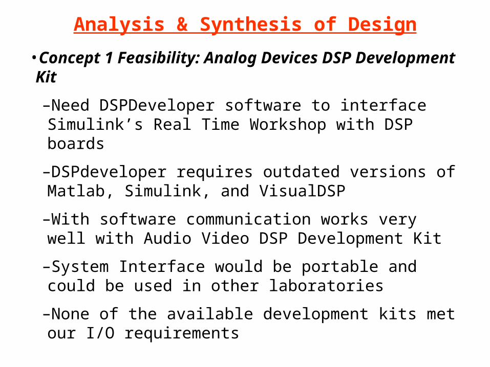
•Concept 1 Feasibility: Analog Devices DSP Development Kit
–Need DSPDeveloper software to interface Simulink’s Real Time Workshop with DSP boards
–DSPdeveloper requires outdated versions of Matlab, Simulink, and VisualDSP
–With software communication works very well with Audio Video DSP Development Kit
–System Interface would be portable and could be used in other laboratories
–None of the available development kits met our I/O requirements

Analysis & Synthesis of Design
•Concept 2: National Instruments USB DAQ Board
Workstation
USB Cable
Ribbon Cable
Ban
ana
Cab
les
Work Bench
System Interface
Matlab and Simulink
Feedback Power Supply
33-100 DC Servo Motor
Interface Board
NI USB DAQPAD

Analysis & Synthesis of Design
•Concept 2 Feasibility: National Instruments USB DAQ Board
–Board has necessary I/O Capabilities
–System Interface would be portable and could be used with any other PC with Labview
–Not supported by Simulink’s Real Time Workshop
–Information from MathWorks states that using Simulink with USB is very difficult if not impossible
–Labview Simulation Interface Toolkit could be used to convert Simulink Diagram to a Labview DLL but would require student’s knowledge of Labview programming to interface the device

Analysis & Synthesis of Design
•Concept 3: National Instruments/Measurement Computing PCI DAQ Card
Workstation
Ribbon Cable
Ban
ana
Cab
les
Work Bench
System Interface
Matlab and Simulink
Feedback Power Supply
National Instruments Conector Block
Interface Board

Analysis & Synthesis of Design
•Concept 3 Feasibility: National Instruments/Measurement Computing PCI DAQ Card
–PCI Card meets all requirements for I/O’s
–PCI Card is supported by Simulink and Real Time Workshop
–No additional software would need to be purchased
–Additional breakout hardware would be necessary
–System Interface would not be portable
–Only NI cards supported by MathWorks are E-Series (top of the line $$)
–Measurement Computing PCI Card is cheaper

Analysis & Synthesis of Design
• Concept 4: Using xPC Target in Matlab to control a PC with I/O Capability
xPC Host PC
RS-232/Ethernet
Ribbon Cable
Ban
ana
Cab
les
Work Bench
System Interface
Matlab and Simulink
Feedback Power Supply
33-100 DC Servo Motor
Interface Board
xPC Boot Software
xPC Target PC

Analysis & Synthesis of Design
•Concept 4: Using xPC Target in Matlab to control a PC with I/O Capability–5 Different PC configurations supported by MathWorks were explored:
•xPC Targetbox from MathWorks with needed I/O’s
•General Standards PC/104 Board with needed I/O’s
•Real Time Devices PC/104 Board with needed I/O’s
•Dell PC with PCI DAQ Card from National Instruments or Measurement Computing
•Shuttle Barebones PC with PCI DAQ Card from National Instruments or Measurement Computing

Analysis & Synthesis of Design
•Concept 4 Feasibility: Using xPC Target in Matlab to control a PC with I/O Capability
–Need to add xPC Target Toolbox to MathWorks license
–Each configuration is already supported by MathWorks
–Each configuration would have the necessary I/O Configuration
–System interface would be portable
–Expandable for other projects and labs
–Each configuration is very different in price per seat

BOM & Costs
Items Lead Time Price for Item Total Cost Per Seat
Concept 1 ItemsDSP Developer downloadable $4,950.00Analog Devices Development Kit 2 weeks Donation?
Concept 2 ItemsLabVIEW Simulation Interface Toolkit downloadable $895.50NI-DAQPAD 6015 1 week $929.23 $929.23
Concept 3 ItemsNI 6052E 3 weeks $1,799.10NI SHC68 (Cable) 3 weeks $85.50NI SCB-68 (I/O Block) 3 weeks $265.50
Measurement Computing PCI DAS1602/16 1 week $715.50Measurement Computing CIO-MINI50 1 week $62.10Measurement Computing CIO-MINI50 1 week $62.10Measurement Computing C100FF-2 1 week $44.10
?
$2,150.10
$883.80
Concepts 1-3 Bill of Materials and Lead Times

BOM & CostsConcept 4 Bill of Materials and Lead Times
Items Lead Time Price for Item Total Cost Per Seat
Concept 4 itemsxPC Toolbox per year (included in each setup) downloadable $600.00
xPC Targetbox 3 weeks $7,330.00 $7,330.00
General Standards PC104P-ADADIO-311 4 weeks $3,195.00 $3,195.00
Real Time Devices CMH6586EX200HR-32 (PC) 5 weeks $571.00Real Time Devices DM6430HR-1 5 weeks $667.00
Dell PC 1 week $329.00Measurement Computing PCI DAS1602/16 1 week $715.50Measurement Computing CIO-MINI50 1 week $62.10Measurement Computing CIO-MINI50 1 week $62.10Measurement Computing C100FF-2 1 week $44.10
$1,238.00
$1,212.80

BOM & CostsConcept 4 Bill of Materials and Lead Times (Continued)
Items Lead Time Price for Item Total Cost Per Seat
Concept 4 items
Dell PC 1 week $329.00NI 6052E 3 weeks $1,799.10NI SHC68 (Cable) 3 weeks $85.50NI SCB-68 (I/O Block) 3 weeks $265.50
Shuttle SS56GV3 PC 1 week $164.00Measurement Computing PCI DAS1602/16 1 week $715.50Measurement Computing CIO-MINI50 1 week $62.10Measurement Computing CIO-MINI50 1 week $62.10Measurement Computing C100FF-2 1 week $44.10
Shuttle SS56GV3 PC 1 week $164.00NI 6052E 3 weeks $1,799.10NI SHC68 (Cable) 3 weeks $85.50NI SCB-68 (I/O Block) 3 weeks $265.50
$2,314.10
$2,479.10
$1,047.80

BOM & Costs
•Bill of Materials common to all concepts:
–Prototype Board $4.29
–34-Way Ribbon Cable Male Connector $3.64 (50 day lead time)

Gantt Chart of Fall Quarter
Events Week 1 Week 2 Week 3 Week 4 Week 5 Week 6 Week 7 Week 8 Week 9 Week 10 Week 11Problem Definition
Developing RequirementsFunction AnalysisDesign Concept 1
Feasibility of Concept 1Design Concept 2
Feasibility of Concept 2Design Conecept 3
Feasibility of Concept 3Design Concept 4
Feasibility of Concept 4Order Parts
Order Software
Fall Quarter 05

SD II Project Plan
Events Week 1 Week 2 Week 3 Week 4 Week 5 Week 6 Week 7 Week 8 Week 9 Week 10 Week 11Receive Software
Receive Parts (Worst Case)Learn Xpc Target (test on PC)
Interface Hardware and SimulinkDebug
Implement Test PlanDemonstration
Order Hardware for Other SeatsReceive HardwareBuild Lab Setups
Winter Quarter 05-06

Our Recommendation for Implementation
•Concept 4 with a PC104 board from Real Time Devices or the Shuttle PC with a PCI DAQ Card from either NI or Measurement Computing covers all of the needs and is most feasible for implementation by the end of winter quarter–Lowest cost per seat–Portable interface–Supported by MathWorks–Expandable

Anticipated Design Challenges/Risk
•Risks:
–Lead time on parts
–Availability of connectors
•Design Challenges:
–Hardware compatibility issues
–Wiring I/O from interface to motor
–Organizing received data from interface

Questions?
Suggestions?