tdp sap velocity logging systems - delta t · sap velocity sensors manual by dynamax ......
TRANSCRIPT

TDP Sap Velocity Logging Systems
S
DELTA-T DEVICEUser Manual for the
SV1-10-UM2

SV1-10 – UM2
Delta-T Devices Ltd TDP Sap Velocity Logging Systems
TDP Sap Velocity Logging Systems Rev Date By Reason 1.1 20 Oct 99 EAP Creation 2 22 Nov 2003 RLS Update to Ls2Win and minor improvement changes
Copyright Copyright © 1999, Delta-T Devices Limited.
All rights reserved. Under the copyright laws, this manual may not be copied, in whole or in part, without the written consent of Delta-T Devices Limited. Under the law, copying includes translation into another language.
Author Edmund Potter.
Trademarks, Licences etc Windows and Excel are registered trademarks of Microsoft Corporation. All other trademarks are acknowledged. Some names referred to are registered trademarks.
Thermal Dissipation Sensors (TDP) are based on a patented design by BREVET INRA (France) and are manufactured under licence by Dynamax Inc, USA.
CE marking The individual parts of the systems described in this manual are CE marked where appropriate, in accordance with European Union EMC directive 89/336/EEC. CE marked products when used as described in the product’s User Manual, conform to the emissions and immunity standards: BS EN 61326: 1998 Class B or as otherwise stated.
Warnings Delta-T Devices Ltd reserves the right to change the designs and specifications of its products at any time without prior notice. The information in this document is subject to change without notice.
Delta-T contact Delta-T Devices Ltd 128 Low Road, Burwell, Cambridge CB5 0EJ, U.K. Web Site: www.delta-t.co.uk e-mail: [email protected] Tel: +44 (0) 1638 742922 Fax: +44 (0) 1638 743155
For Technical Support, please contact your local agent or distributor in the first instance. e-mail: [email protected]
Rev 2, 22 Nov 2003 page 2 of 21

SV1-10 – UM2
Delta-T Devices Ltd TDP Sap Velocity Logging Systems
Contents
Introduction ------------------------------------------------------------------------------------------------------- 4 Scope of this manual ------------------------------------------------------------------------------------------------------ 4 Unpacking the consignment -------------------------------------------------------------------------------------------- 4
System Description in Outline ------------------------------------------------------------------------------ 5 System components ------------------------------------------------------------------------------------------------------- 5 TDP Sap Velocity sensor overview ----------------------------------------------------------------------------------- 5 Enclosure---------------------------------------------------------------------------------------------------------------------- 6 Power supplies -------------------------------------------------------------------------------------------------------------- 6
AVRD Dual Adjustable Voltage Regulator ---------------------------------------------------------------------------------------- 6 TDP sensor stem installation ------------------------------------------------------------------------------------------- 6
Logger and Extension Cables -------------------------------------------------------------------------------------------------------- 6 System build------------------------------------------------------------------------------------------------------------------ 7 Sap Flow software diskette---------------------------------------------------------------------------------------------- 7
DL2e Logger Program - TDP sensors ---------------------------------------------------------------------------------------------- 7 Excel spreadsheet ------------------------------------------------------------------------------------------------------------------------ 7
Data Logger Operation DL2e -------------------------------------------------------------------------------- 8 Logger hardware ------------------------------------------------------------------------------------------------------------ 8 Channel assignment ------------------------------------------------------------------------------------------------------- 8 The 10-TDP sensor system ---------------------------------------------------------------------------------------------- 8 Modifying the DL2e Program file -------------------------------------------------------------------------------------- 9
Sampling intervals and averaging periods --------------------------------------------------------------------------------------- 9 System Assembly and Setup -------------------------------------------------------------------------------10
Preliminary bench tests -------------------------------------------------------------------------------------------------10 Warnings! -----------------------------------------------------------------------------------------------------------------------------------10 Configure the logger --------------------------------------------------------------------------------------------------------------------10
Wiring connections -------------------------------------------------------------------------------------------------------11 Single TDP sensor -----------------------------------------------------------------------------------------------------------------------11 Zero checking the readings-----------------------------------------------------------------------------------------------------------11 Checking the heater voltage reading----------------------------------------------------------------------------------------------12 Checking TDP sensor flow readings ----------------------------------------------------------------------------------------------12
Wiring Harness: 10-TDP sensor system ---------------------------------------------------------------------------13 Harness assembly -----------------------------------------------------------------------------------------------------------------------14 Grounding connections----------------------------------------------------------------------------------------------------------------14 12V Power systems----------------------------------------------------------------------------------------------------------------------14 Mains powered systems - Warning ------------------------------------------------------------------------------------------------14
Field installation------------------------------------------------------------------------------------------------------------15 Tuning the heater voltages -----------------------------------------------------------------------------------------------------------15
Data Processing ------------------------------------------------------------------------------------------------16 Using Ls2Win with Excel for data files -----------------------------------------------------------------------------16
Getting the data file into Excel-------------------------------------------------------------------------------------------------------16 The Sap Velocity spreadsheet-----------------------------------------------------------------------------------------17
The TDP Sap Velocity calculation --------------------------------------------------------------------------------------------------17 Setting the value for dTmax ----------------------------------------------------------------------------------------------------------17 Applying flow filter conditions-------------------------------------------------------------------------------------------------------17 Flow Accumulator------------------------------------------------------------------------------------------------------------------------18 Recalculating sap velocity with new parameters -----------------------------------------------------------------------------18 Graphing sap velocity ------------------------------------------------------------------------------------------------------------------18
Warranty and Service -----------------------------------------------------------------------------------------19 Terms and Conditions of Sale-----------------------------------------------------------------------------------------19 Service and Spares--------------------------------------------------------------------------------------------------------19
Troubleshooting ------------------------------------------------------------------------------------------------20 Routine Maintenance -----------------------------------------------------------------------------------------------------20 Technical Support ---------------------------------------------------------------------------------------------------------20
Rev 2, 22 Nov 2003 page 3 of 21

SV1-10 – UM2
Delta-T Devices Ltd TDP Sap Velocity Logging Systems
Introduction
Scope of this manual This user manual is for our standard SV1-10-DL2 system with ten Thermal Dissipation Sensor (TDP) sensors, using a DL2e data logger. It describes the installation and operation of a sap velocity measurement system and the ancillary equipment required for you to log data from the sensors, and process the results to give readings of sap velocity, and hence sap mass flow.
It will frequently be necessary to refer to other user manuals or items, which form the component parts of your system. They are listed below with a brief explanation of the relevant content.
1. Sap Velocity Sensors Manual by Dynamax (TDP Manual). This is your prime source of reference for everything to do with the practical handling of the TDP sensors, plus the theory of their operation.
2. The AVRD Voltage Regulator, User Manual Installation Guide also from Dynamax (AVRD Manual), or an equivalent unit supplied by Delta-T.
3. The DL2e Data Logger Getting Started Manual and software Ls2Win. A reasonable level of familiarity with the logger manuals, and online documentation will be assumed, and you should have worked through at least the tutorial sections.
4. The Delta-T Sap Flow software diskette (type SFL1) contains example configurations, programs, and Excel spreadsheets for all Delta-T sap flow systems.
5. The Delta-T Enclosure User Manual describes the mounting of the enclosure on a mast or pole, and shows the installation with a DL2e data logger.
6. User Documentation for battery and solar power systems will also be included, if they are supplied by Delta-T.
Unpacking the consignment Check for any damage that may have occurred to the consignment in transit. Check that the contents of the consignment agree with the Packing List. If any damage or shortage is apparent, notify the distributors and the carriers immediately. Make a note of any equipment serial numbers, as these will be needed in any subsequent warranty claims, repairs or recalibration.
Rev 2, 22 Nov 2003 page 4 of 21

SV1-10 – UM2
Delta-T Devices Ltd TDP Sap Velocity Logging Systems
System Description in Outline
System components A typical outdoor sap velocity system installation is shown in the diagram.
Sap velocity sensors are installed on the trunks and stems of trees and plants. Extension cables carry the sensor heater power, and route the sensor signals to a data logger contained in the enclosure. In general, the logger is sited close to the sensors so that the cost and vulnerability of extension cables is minimised.
Also housed in the enclosure are the voltage regulators for the heaters such as the AVRD, and other non-environmentally proofed accessories, which could include modems for data communications. The enclosure can be pole mounted, but may well be mast mounted if other agro-met sensors are included in the system.
High capacity batteries are often needed for the sensor heaters, and may require solar panels for recharging in remote situations. The panels must be sited for optimum sunlight interception, and the batteries are generally housed close by, in a battery box. Power-carrying cables may be needed to run from the batteries to the logger enclosure. Where mains power is available, the charger is often housed in a separate weatherproof box, for electrical safety reasons.
After you have established the general layout of your site and experiment, you will need to consider each of the main components in more detail.
TDP Sap Velocity sensor overview Refer to the TDP Manual. You should read the following (bold) sections of the Dynamax TDP Manual before attempting to install TDP sensors.
§ 1 Introduction § 2 Explanation of Method and Principles § 3 TDP Sensor and System Description § 4 Sensor Specifications § 5 Brief Summary DL2e Logger specifications § 6 Software Programming and Calculations § 7 Sensor Installation Appendices: • Dynamax TDP tests comparison graphs. • TDP-30 and TDP-80 probe wiring connections and pin-outs. • References to scientific papers.
Rev 2, 22 Nov 2003 page 5 of 21

SV1-10 – UM2
Delta-T Devices Ltd TDP Sap Velocity Logging Systems
Enclosure If supplied by Delta-T, please refer to the Enclosure manual for details of mast or pole mounting, and the disposition of the logger and other internal components. A copper grounding rod and strap is recommended. This can be obtained locally or supplied by Delta-T (type WS-GRK).
The DIN rail mounted double decker terminals are the most appropriate termination point for combining power connections to the various TDP sensor sensors.
If an AVRD voltage regulator is supplied, it can be mounted on the inside of the enclosure door with the adhesive Velcro straps provided, to give a detachable installation.
The DL2e data logger is also fitted with detachable terminal connectors for ease of installation.
Power supplies Delta-T systems are normally designed around 12 V dc power.
Systems involving only TDP-30 sensors can be designed to work down to 7.5V dc power (the minimum for the DL2e data logger). However, TDP-80 sensors (which require at least 7.5V heater power) must in general be run from 12V systems.
If the power systems are supplied by Delta-T, please refer to the relevant User Manuals (SOL1,2 or 3, or similar, for solar panel charging systems). Where solar panels and batteries are sited remote from the logger enclosure, you may need to provide power supply cables of appropriate load carrying capacity, if they have not already been included in your order.
AVRD Dual Adjustable Voltage Regulator Sap velocity sensor heater voltages must be initially set up to a particular voltage level. Thereafter, fine adjustments of the voltage may be needed in situ for optimum performance. The AVRD is supplied for this purpose. It has two adjustable outputs, each capable of powering a large number of sap velocity sensors at the same voltage, although in practice the need for individual voltage adjustment limits this usually to about four or five sensors per output.
Consult the AVRD Manual for detailed specifications.
TDP sensor stem installation Read the TDP Manual § 7 to help you plan exactly where on the stems you will position the sensor needles. Preparation of the stems will be needed at the time of installation.
Each TDP sensor is fitted with a cable connector close to the needles, so that it can easily be installed in the stems without long cables attached.
Logger and Extension Cables A short (3m) logger cable is provided with each TDP sensor. The logger-end of this cable terminates with bare wire tails.
Standard attenuator resistors are provided for the heater voltage sensing function. These are supplied loose, and you will need a soldering iron to make the connection.
Extension cables in a variety of different lengths are available for situations where the stems are remote from the logger. Extension cables are fitted with appropriate connectors on each end.
Rev 2, 22 Nov 2003 page 6 of 21

SV1-10 – UM2
Delta-T Devices Ltd TDP Sap Velocity Logging Systems
System build This manual assumes you will be using a DL2e data logger in our Enclosure (M2-ENCL), and so we provide:
• an example logger program (SV1-1a.pg2) on disk for initial logger setup, and a wiring connection diagram for one TDP sensor using an AVRD, and
• an example logger program (Sv1-10b.pg2) and wiring harness diagram for a system with 10 TDP sensors and an AVRD, using both its output channels.
By appropriate use of these, you should be able to build your own customised system, which may involve different numbers of TDP sensors, and may include additional meteorological or soil sensors.
Sap Flow software diskette Files for logger programs and data processing are provided on the diskette (type SFL1).
A README.txt file, which you should read, contains details of the files on the diskette, and may contain late news not included in this User Manual.
You will need to edit the files to suit your individual setup, so you are recommended to protect the original files supplied, and keep them somewhere safe.
DL2e Logger Program - TDP sensors A logger program specifies which logger channels are connected to the various TDP sensor outputs, and sets the data sampling and reading intervals of the logger.
The logger program files (*.pg2) for use with the DL2e can be modified and edited using the Ls2Win logger software.
Excel spreadsheet The example Excel spreadsheet enables you to calculate the sap velocity readings from DL2e data files obtained with TDP sensors.
Rev 2, 22 Nov 2003 page 7 of 21

SV1-10 – UM2
Delta-T Devices Ltd TDP Sap Velocity Logging Systems
Data Logger Operation DL2e You will need to refer to the DL2e logger Getting Started Manual, Ls2Win software and online documentation for detailed instructions until you become familiar with its operation.
Logger hardware For the example logger program and sensor connections shown in this manual, the DL2e logger is assumed to be fitted with one (or more) LAC1 analogue input cards set to the 15-channel mode.
It is also possible to use the LFW1 and ACD1 input cards by following similar principles to those given here, but you will have to consult the online DL2e documentation for detailed connection information.
Channel assignment Some details of the example DL2e program file (SV1-1a.pg2) printout are shown below.
Channel 11 is used simply to monitor the heater voltage to ensure it remains constant. It is not essential to include this in the program, because the heater voltage data is not used in the sap velocity calculation. However, it is good experimental practice to be able to verify later that the heater voltage has in fact remained constant.
The 10-TDP sensor system This system is based on the assumption that groups of five TDP sensors are connected to each of the two power output channels of one AVRD. The configuration file is SV1-10b.pg2.
Again, it is not essential to log the AVRD voltages – just good experimental practice.
The LAC1 input card has 15 differential voltage analogue channels. The SV1-10 program leaves three channels spare.
If you dispense with the AVRD channels, then you can run a maximum of 15 TDP sensors on one LAC1 input card. The DL2e can easily be expanded with further LAC1 input cards (up to 60 analogue channels) if you want to run more sensors.
Rev 2, 22 Nov 2003 page 8 of 21

SV1-10 – UM2
Delta-T Devices Ltd TDP Sap Velocity Logging Systems
Modifying the DL2e Program file When you have decided on the assignment of sensors to channels (you can of course add other types of sensors to any spare channels left on the LAC1 input card), then you must create a new program file.
You can load the above program file into the Ls2Win software, edit it, and then save it with a new program filename.
The Ls2Win software for the DL2e contains the sensor code TDP for the thermocouple output (simply measured in mV), and the code TDH for the attenuated heater voltage. An attenuator is necessary because the heater voltage is greater than the maximum allowable 2096 mV input voltage for the DL2e logger. A differential voltage input channel must be used for this measurement.
If you are using the earlier DOS version of the LS2e software that does not already contain these in the sensor library, you can simply load the above program, and save the sensor to your sensor library. Otherwise, you can simply type in the details.
Sampling intervals and averaging periods You must also set the sampling interval and data compression period in the logger program file.
For short term experiments (1-2 days) then a 5 or 10 second sample rate is recommended. For longer term experiments (weeks) then 1 minute sampling will reduce the logger power consumption.
For the averaging period, 5 or 10 minute averages are appropriate for short term experiments, and half- or one hour periods for longer term studies. There is no fixed rule. In fact, you are free to select any combination of sample and data compression intervals that the DL2e will allow. There is always a trade-off between the amount of data produced, logger power consumption and data memory space.
Rev 2, 22 Nov 2003 page 9 of 21

SV1-10 – UM2
Delta-T Devices Ltd TDP Sap Velocity Logging Systems
System Assembly and Setup
Preliminary bench tests As with any complex system, you will probably want to test as many of the individual components as you can before setting up the whole installation in the field.
It is not particularly easy to simulate the normal operation of TDP sensors on the bench, however it is certainly possible to verify that the thermocouple and heater outputs are properly read by the logger.
Warnings! • Before connecting heater power to the TDP sensor, make sure that the voltage to be applied is
approximately the correct value (3V for TDP-30, 7.5V for TDP-80), or less.
• The heated needle of the TDP sensor can get uncomfortably hot if left in air with full heater power connected.
For the latter reason, we recommend that you use a block of wood of suitable dimensions (any type of wood will do), and drill it with the drill bits provided. Mount the TDP needles in the wood block before applying correct power levels to the heater. This will ensure that the heated needle will not be subjected to excessive temperatures.
Configure the logger First you must load the Ls2Win software into your PC, and check its operation.
Then load the SV1-1y.pg2 file, and after connecting the PC to your DL2e with the RS232 cable, send the configuration to the logger.
For initial “static” tests, this arrangement will be sufficient. Later you will want to edit and refine the configuration before sending it to the logger once more.
Note that an attenuator is used to monitor the supply voltage on channel 11. As previously mentioned, this measurement channel is optional. Attenuator resistors are provided with the TDP sensor logger cable. You will need a soldering iron to make the connections as shown. The given resistance values attenuate the voltage by a factor of 1/11 (0.091). Multiply the mV logger reading obtained by 11 to calculate the heater power voltage.
Rev 2, 22 Nov 2003 page 10 of 21

SV1-10 – UM2
Delta-T Devices Ltd TDP Sap Velocity Logging Systems
Wiring connections
Signal HI (white)Signal LO (green)
Heater V+ (red)Heater 0V (black)
Signal HI* (brown)
Screen to Logger frame or 61- or 62-
DC POWER 6.5 to 28Vdc
70 mA per probe
+ -
BK
– 61 + – 62 + 63 NO NC 64 NO NC
GN BN W
– 2 +– 1 + – 3 + – 4 + – 5 +
1K
10K
BK
VIN ? GND ? GND ?
VOUT2 ? VOUT1 ? CLINE ?
AVRD
1
2
OFFON
–12+–11+ –13+ –14+ –15+
*Note that only the TDP-80 has the extra Signal HI brown wire. This connects its two thermocouples in parallel to give an average needle temperature.
Single TDP sensor Take one TDP sensor (preferably mounted in a wood block) and your AVRD, and connect the logger cable to the DL2e screw terminal connector blocks as shown in the wiring diagram. If the attenuator resistors have been supplied loose, you must now connect them.
For the present, DO NOT connect the heater 0V and V+ to the AVRD.
Zero checking the readings From the DL2e logger keypad, wake the logger and read the sensors on channels 1 and 11, or read these directly on the PC under Ls2Win.
At this stage, the readings should be near 0.000 mV, and may be slightly positive or negative. Channel 1 may be gradually changing. Any large or rapidly fluctuating (noisy) values indicate a lack of proper connection to the relevant channel. You must identify the source of the trouble and eliminate it.
Rev 2, 22 Nov 2003 page 11 of 21

SV1-10 – UM2
Delta-T Devices Ltd TDP Sap Velocity Logging Systems
Checking the heater voltage reading Before connecting the TDP sensor heater wires to the AVRD, read all the warnings in the AVRD manual
Make sure the AVRD is switched off. Connect a suitable voltage supply to the AVRD, and switch it on. Set Vout1 to approximately the correct value (3V for TDP-30, 7.5V for TDP-80). Check this with a voltmeter if you can.
Switch the AVRD off. Then connect the heater 0V and V+ wires from your TDP sensor. Switch on the AVRD briefly (10 seconds maximum), then off again.
Observe the reading of channel 11 on the logger. You should see the attenuated voltage in mV. Multiplying this by 11 will give the actual voltage applied to the TDP heater.
Almost immediately, the channel 1 reading for the TDP sensor will start to increase smoothly, in response to the temperature rise generated in the heater. The TDP thermocouple is Copper-Constantan, for which the temperature coefficient is 40 µV/°C (0.040 mV/°C).
If the AVRD is left on, the TDP sensor reading will tend to stabilise after a few minutes at around 0.5 mV, within a few tenths of a mV. This corresponds to a temperature reading of 5 to 15 °C, which is the difference in temperature between the heated needle and the reference needle of the probe. The actual magnitude depends on the type of wood and the spacing of the needles within it, and is not of importance during this part of the test.
These simple checks broadly establish the satisfactory functioning of the TDP sensor, logger and AVRD.
Checking TDP sensor flow readings It is not easy to get realistic data readings from a TDP sensor unless it is actually installed in a tree or plant stem, and the system has been run continuously throughout two or three days and nights.
Ideally you will want to practice installing a TDP sensor and taking real readings in order to become familiar with the practical techniques involved. If you have access to a living plant stem of the appropriate diameter, you can install the TDP sensor on it. Thoroughly read the TDP Manual §7 before you attempt this.
You can use the existing connector wiring and logger configuration, but you may want to reduce the averaging period of the readings to, say 10 minutes (by changing the logger configuration) so that you can see changes more quickly.
The typical shape of the raw data outputs from a TDP sensor can be seen in the TDP Manual Appendix “TDP Signal Chart”. Each night the mV output rises to a plateau before dawn. This is the time when sap flow is expected to decrease to zero. The temperature difference at this point (“dTmax”) is the vital parameter that is used in subsequent sap velocity calculations for that particular TDP sensor installation. After sunrise, the mV reading may well drop very rapidly if the conditions for high transpiration are favourable.
Once you have obtained some meaningful data from a real plant, you can then practice using the Excel spreadsheet provided on the Delta-T software diskette to convert your data into readings of sap velocity.
Rev 2, 22 Nov 2003 page 12 of 21

SV1-10 – UM2
Delta-T Devices Ltd TDP Sap Velocity Logging Systems
Wiring Harness: 10-TDP sensor system
The wiring harness shown above implements the 10-TDP sensor logger configuration (SV1-10y.pg2) within the Delta-T M2-ENCL enclosure. The physical layout of the main components is indicated diagrammatically.
A single external power supply (nominal 12 V) powers the logger and the TDP sensor heaters through the AVRD. The logger can also contain its own internal alkaline batteries which will power the logger (only) if the external supply fails or is disconnected for any reason.
Rev 2, 22 Nov 2003 page 13 of 21

SV1-10 – UM2
Delta-T Devices Ltd TDP Sap Velocity Logging Systems
Harness assembly The layout is conceived so that nearly all the wiring connections can be made and system checks carried out in the workshop before installing the system in the enclosure in the field.
• Pass the TDP sensor extension cables (wire tails) through the sealing glands in the gland plate at the base of the enclosure.
• Connect cable screens and heater wires to the 10 double decker power terminals and earth mounted on the DIN rail.
• Connect the remaining TDP sensor wire tails to the logger screw terminal connector’s, channels 1 to 10.
• Connect wires from Vout1 and 0V to the attenuator resistors in channel 11. Refer to the earlier detailed wiring diagram for the exact connections. Repeat this for Vout2 and 0V and connect to channel 12. These are the optional heater voltage monitoring channels.
• Make connections from the double decker terminals to the AVRD as shown, with wires of sufficient length so that the enclosure door can be fully opened when in use.
At this stage, you can carry out further bench tests of the logger and TDP sensors to check the integrity of all the system components.
The hole for the gland plate in the base of the enclosure is large enough to allow you to thread the pre-wired AVRD and logger connectors into the enclosure. The AVRD can be conveniently mounted on the inside of the enclosure door by means of two adhesive Velcro strips.
• All that remains for system assembly in the field is to mount the logger on to the (removable) back plate of the enclosure, fit the gland plate with extension cables, complete the grounding connections, and finally to bring the external power supply cable into the enclosure.
Grounding connections You must take care to avoid all possibility of “ground loops”. Ground loops do not affect the safety of the system but they can contribute to small or variable error voltages in your data readings.
Follow the “star connection” concept (a single path to ground from each component) employed in the diagram. Use substantial braided leads that help to disperse high frequency spike voltages that may be induced by nearby electrostatic discharge.
The logger frame terminal is connected to the enclosure back plate. Do NOT connect logger analogue ground terminals to the logger frame, but be aware that DL2e logger digital ground terminals 61- and 62- are different and are connected to frame within the logger itself.
Connect the extension cable screens to a single braid and then to a corner case stud of the enclosure.
Bring a further braid connection from this corner stud, through the gland plate, either to a screw tapped into the aluminium mast, or, if there is any doubt about the grounding of the mast itself, to a standard copper grounding rod.
12V Power systems If Delta-T has supplied an appropriate system of batteries and/or solar panels, please consult the User Documentation that accompanies them.
If you are providing your own power source, please follow the above as general guidelines.
Mains powered systems - Warning If mains voltages are used to provide the system power, it is vital to comply with local electrical regulations. Electrical isolation and correct earthing are essential to minimise potential risk to health from electric shock. Please follow any instructions provided with such equipment and in any doubt seek a professional installation service or advice.
Rev 2, 22 Nov 2003 page 14 of 21

SV1-10 – UM2
Delta-T Devices Ltd TDP Sap Velocity Logging Systems
Field installation The initial setting up of your experiment will require the following steps:
• Install the enclosure
• Install the logger, AVRD, and TDP sensor logger cables in the enclosure
• Install the TDP sensors on the stems, and connect to their extension cables
• Set up the external power supply.
Before switching on the external power to the TDP sensor heaters, you can do preliminary checks of all the sensors via the front panel display on the DL2e logger (or by interrogating the logger with a portable PC). Make sure that the voltage levels Vout1 and Vout2 are set approximately correct for your particular gauges.
If you experience difficulties, the Zero Checking and Heater Test procedures described earlier for individual TDP sensors are the best technique to help you identify faulty connections or wiring. Interchanging similar components can also be used to isolate a particular problem.
Switch on the AVRD and monitor the heater voltage channels to check that the heaters are receiving the correct voltage, then start logging.
After your logger has had time to record three or four averaging periods, you can download the data from the logger to a PC (or to a Psion Workabout using the Delta-T Attach software), and then inspect the data for any obvious errors or difficulties.
During the next few days, you will inspect and analyse the data in order to fine-tune the heater voltage levels, and other practical aspects of the TDP sensor fit and insulation of the plant stems. When these matters have been satisfactorily resolved the daily attention can be relaxed, but you would be well advised to check every two or three days if possible.
Tuning the heater voltages The target value for dTmax for an individual TDP sensor is about 6 to 8 °C. It does not seem to be critical, and it should be consistent from night to night (always assuming the sap flow does in fact reduce to zero). Over a period of days or weeks, it may gradually drift.
In order to change dTmax during the initial experimental setup, or to reduce gradual drift, the exact voltage setting of the AVRD can be adjusted using the relevant output channel adjuster. The multiturn potentiometers on the AVRD provide about 1 volt change per revolution. Increasing the voltage will increase dTmax, and vice versa. You will have to experiment by trial and error, monitoring the new voltage applied, and observing the new overnight dTmax.
If you have a number of TDP sensors connected in parallel to one output channel of the AVRD, you will have to set the AVRD to give the best compromise of dTmax values for all the TDP sensors. It is for this reason that the recommended maximum number of TDP sensors per output channel is limited to four or five.
Rev 2, 22 Nov 2003 page 15 of 21
SV1-10 – UM2
Delta-T Devices Ltd TDP Sap Velocity Logging Systems
Data Processing The “raw” millivolt readings from TDP sensors must be processed to give values of sap velocity. For your convenience, a Microsoft Excel spreadsheet has been set up which includes the necessary calculations. The theoretical basis for the formulae used is covered in detail in the TDP Manual §6. The conversion factor to turn mV readings into °C for the TDP thermocouple (Copper-Constantan) is 40 µV/°C (0.040 mV/°C).
TDP-80 probe needles each have two thermocouples for temperature sensing. Wiring these as shown in the wiring connections diagram gives the average temperature for the whole length of the needle. Thus only a single temperature difference reading is obtained – just as for the TDP-30 probe.
Using Ls2Win with Excel for data files The DL2e data logger can produce data files in either binary (*.bin) or ASCII (*.dat) format. (The fastest way of collection is binary format).
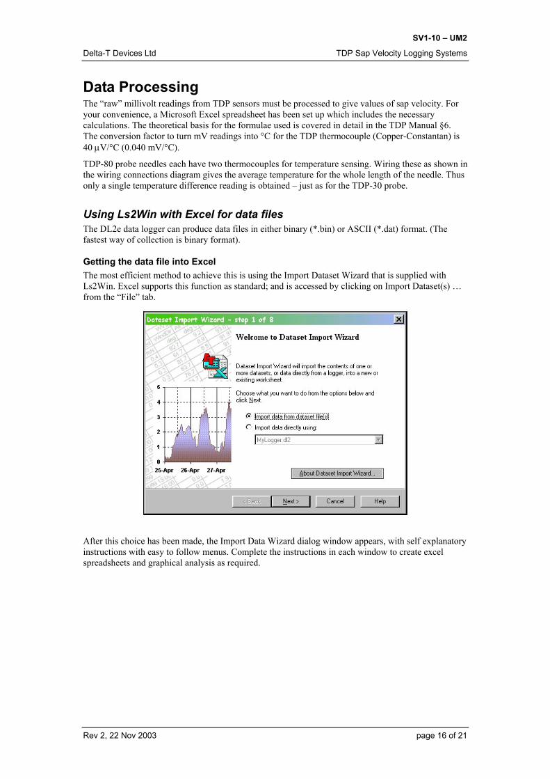
Getting the data file into Excel The most efficient method to achieve this is using the Import Dataset Wizard that is supplied with Ls2Win. Excel supports this function as standard; and is accessed by clicking on Import Dataset(s) … from the “File” tab.
After this choice has been made, the Import Data Wizard dialog window appears, with self explanatory instructions with easy to follow menus. Complete the instructions in each window to create excel spreadsheets and graphical analysis as required.
Rev 2, 22 Nov 2003 page 16 of 21

SV1-10 – UM2
Delta-T Devices Ltd TDP Sap Velocity Logging Systems
The Sap Velocity spreadsheet The file TDPCALCx.xls is included on the Sap Flow software diskette. It is an Excel workbook saved in 5.0/95 format. It has been annotated and designed with a minimum of complex features, so that a relatively inexperienced user will be able to copy and modify it without difficulty.
The workbook contains three sheets. The first sheet, named “Calcn” is the one you will routinely use for processing data from each TDP sensor. A printout of this sheet is included at the end of this manual. The second sheet, named “Example” shows what the calculation looks like when performed on actual data obtained from a tree during sunny days. The third sheet is left blank.
The TDP Sap Velocity calculation On the Calcn sheet, you will find brief explanations of all the parameters that must be specified, and the operations to calculate sap velocity.
You will need to start a sheet like this, in its unmodified form, for each TDP sensor, so it is a good idea to copy the sheet immediately, rename the new sheet and use that.
In column B you must input important factors specific to an individual TDP sensor. For your first trial, you must put your best estimates in the Stem and Probe parameters cells, and you must specify the correct reading interval of your data (the time between the successive rows of your data file).
Now copy from the .xls data file you have just prepared the columns of data corresponding to columns A:F. If your TDP sensor was connected to channel 1 on the DL2e logger, these will be the identical group of columns A:F in your data spreadsheet, otherwise you will have to choose the appropriate columns.
It is good practice to routinely include the error flag columns associated with the data, and not to ignore them. This can help in interpretation of data calculations later.
After you have copied the formula cells in columns G:M into all the rows below to the full extent of your data, you should obtain a complete sheet of figures.
Do not be worried at this stage if some of the cells are reporting errors; the columns G (dT degC) and M (AVRDCh1 HtrV) should be giving sensible results.
If you save your spreadsheet files complete, they can be used for data archiving, and you can always return to them later if you wish to recalculate sap velocity values with revised parameters.
Setting the value for dTmax For the next stage of the analysis, you must inspect the values of dT obtained overnight for a particular sensor, and choose the highest value reached. Enter this value into the dTmax column in the spreadsheet in row “000”.
The calculation uses this value of dTmax in the formula for sap velocity. From time to time you may wish to reset the value of dTmax, for instance, after you have changed the heater voltage supply, or because its value has drifted slightly from your original setting. Simply enter the new value into the dTmax column in the row from which you want the new value to apply (overwrite the existing formula). All subsequent rows will replicate the new value. In this way you can always see the value that has been used in the calculation, throughout the data set.
If (dTmax-dT) becomes negative, the Excel formula will produce an error, and you must adjust dTmax to remove it.
Applying flow filter conditions The final stage of the process is to analyse the unrealistic or erroneous values of flow rates, otherwise the accumulating sap velocity amount (Facc) can be considerably in error.
The most likely cause of calculation error is when dT becomes very small or zero. This can be the case if the heater power is not switched on (or has been disconnected) for any reason. It could also result from a high sap flow situation combined with excessive thermal errors in the dT reading.
A simple filter has been included in the spreadsheet, which will set the flow rate as zero if dT goes below a certain temperature difference (0.25 °C). You can set this value to whatever you wish.
Rev 2, 22 Nov 2003 page 17 of 21
SV1-10 – UM2
Delta-T Devices Ltd TDP Sap Velocity Logging Systems
Flow Accumulator The flow accumulator is set to zero initially in row “000”. If you want daily totals in addition, for example, you can utilise the spare spreadsheet columns from N onwards.
Recalculating sap velocity with new parameters For the initial calculation of sap mass flow, you must include in the spreadsheet your best estimate of the value of As (the cross-sectional area of sapwood in the stem). Later, after an experiment has been completed, you may obtain a better value. Simply overwrite the As value in the stem and probe parameters section, and the spreadsheet will recalculate the revised flow rates.
Sap mass flow is simply proportional to cross sectional area, so if you wish to include increasing values of As (during the course of a long experiment, for example), it would be straightforward to calculate an adjustment by inserting an extra column into the spreadsheet.
Graphing sap velocity Excel’s graphing facilities are very powerful, and well repay the time spent learning how to use them effectively. You should quite quickly be able to construct charts showing any aspect of your data. No chart template has been provided.
Rev 2, 22 Nov 2003 page 18 of 21

SV1-10 – UM2
Delta-T Devices Ltd TDP Sap Velocity Logging Systems
Warranty and Service
Terms and Conditions of Sale Our Conditions of Sale (ref: COND: 1/00) set out Delta-T's legal obligations on these matters. The following paragraphs summarise Delta-T's position but reference should always be made to the exact terms of our Conditions of Sale, which will prevail over the following explanation. Delta-T warrants that the goods will be free from defects arising out of the materials used or poor workmanship for a period of twelve months from the date of delivery. Delta-T shall be under no liability in respect of any defect arising from fair wear and tear, and the warranty does not cover damage through misuse or inexpert servicing, or other circumstances beyond our control. If the buyer experiences problems with the goods they shall notify Delta-T (or Delta-T’s local agent) as soon as they become aware of such problem. Delta-T may rectify the problem by supplying faulty parts free of charge, or by repairing the goods free of charge at Delta-T's premises in the UK, during the warranty period, If Delta-T requires that goods under warranty be returned to them from overseas for repair, Delta-T shall not be liable for the cost of carriage or for customs clearance in respect of such goods. However, we much prefer to have such returns discussed with us in advance, and we may, at our discretion, waive these charges. Delta-T shall not be liable to supply products free of charge or repair any goods where the products or goods in question have been discontinued or have become obsolete, although Delta-T will endeavour to remedy the buyer’s problem. Delta-T shall not be liable to the buyer for any consequential loss, damage or compensation whatsoever (whether caused by the negligence of the Delta-T, our employees or agents or otherwise) which arise from the supply of the goods and/or services, or their use or resale by the buyer. Delta-T shall not be liable to the buyer by reason of any delay or failure to perform our obligations in relation to the goods and/or services, if the delay or failure was due to any cause beyond the Delta-T’s reasonable control.
Service and Spares Users in countries that have a Delta-T Agent or Technical Representative should contact them in the first instance. Spare parts for our own instruments can be supplied from our works. These can normally be despatched within a few working days of receiving an order. Spare parts and accessories for sensors or other products not manufactured by Delta-T, may have to be obtained from our supplier, and a certain amount of additional delay is inevitable. No goods or equipment should be returned to Delta-T without first obtaining the agreement of Delta-T or our agent. On receipt at Delta-T, the goods will be inspected and the user informed of the likely cost and delay. We normally expect to complete repairs within a few working days of receiving the equipment. However, if the equipment has to be forwarded to our original supplier for specialist repairs or recalibration, additional delays of a few weeks may be expected.
Rev 2, 22 Nov 2003 page 19 of 21

SV1-10 – UM2
Delta-T Devices Ltd TDP Sap Velocity Logging Systems
Troubleshooting
Routine Maintenance In general, TDP sap flow systems are simple to operate once the initial installation has been satisfactorily achieved. As with all field set-ups, visual inspection of the site and data collection every few days is the ideal way to track down problems quickly and avoid loss of data.
If problems occur, you must try to identify which components are the source of the trouble, and then consult the relevant documentation.
For sap flow systems questions, consult this manual.
For the TDP sensors operation and installation, consult the TDP Manual.
For the AVRD, consult the AVRD Manual.
For the DL2e logger, power supplies and other sensors supplied by Delta-T, please consult the relevant User Manual or user documentation provided.
Technical Support Technical Support is available on Delta-T products and systems. Users in countries that have a Delta-T Agent or Technical Representative should contact them in the first instance. Technical Support questions received by Delta-T will be handled by our Tech Support team. Your initial enquiry will be acknowledged immediately with a “T number” and an estimate of time for a detailed reply (normally a few working days). Make sure to quote our T number subsequently so that we can easily trace any earlier correspondence. In your enquiry, always quote instrument serial numbers, software version numbers, and the approximate date and source of purchase where these are relevant.
Contact details:
Tech Support Team Delta-T Devices Ltd 128 Low Road, Burwell, Cambridge CB5 0EJ, U.K. email: [email protected] Web site: www.delta-t.co.uk Tel: +44 (0) 1638 742922 Fax: +44 (0) 1638 743155
Rev 2, 22 Nov 2003 page 20 of 21

SV
1-10
– U
M2
Del
ta-T
Dev
ices
Ltd
TD
P S
ap V
eloc
ity L
oggi
ng S
yste
ms
Sap
velo
city
spre
adsh
eet (
prin
tout
)
1 2 3 4 5 6 7 8 9 10 11 12 13 14 15 16 17 18 19 20 21 22 23 24 25 26 27 28 29 30
AB
CD
EF
GH
IJ
KL
MN
OP
DL2
e TD
P Sa
p Ve
loci
ty c
ompu
tatio
nD
elta
-T D
evic
es L
td
Ste
m a
nd p
robe
par
amet
ers:
Inpu
t:Fo
rmul
a (S
ee m
anua
l):U
nits
:Im
plem
enta
tion:
Ser
ial N
o.TD
P#1
<< Y
our P
robe
iden
tifie
rTD
P te
mp.
coef
f't 4
0uV
/deg
C:
(Not
e co
nver
sion
fact
ors
whe
re a
ppro
pria
te)
As
99cm
2<<
Ste
m s
ap w
ood
X-se
ctio
n ar
eadT
=mV/
0.04
0de
g C
D28
/0.0
4K
=(dT
max
-dT)
/dT
Not
eva
luat
ed s
epar
atel
yH
eate
r:V
=0.0
119*
K^1
.231
cm/s
0.01
19*P
OW
ER
((H
28-G
28)/G
28,1
.231
)A
ttenu
ator
0.09
1<<
Div
ider
atte
nuat
or R
1/(R
1+R
2)H
trV=m
V/a
ttenu
ator
/100
0V
F28/
$B$8
/100
0Fi
lter c
ondi
tions
:Fs
=As*
V*3
600
cm3(
g)/h
$B$5
*I28
*360
0dT
<0.
25de
g C
Avo
ids
spur
ious
hig
h flo
w v
alue
sIf
dT<0
.25,
set
Fs
to z
ero
IF(G
28<$
B$1
0,0,
J28)
Dat
a:R
eadi
ng in
terv
al10
min
utes
<<Y
our d
ata
read
ing
inte
rval
Facc
=Pre
viou
s+In
crem
ent
gL2
7+K
28*$
B$13
/60
Spr
eads
heet
ope
ratio
n:1.
Ent
er y
our s
tem
and
pro
be p
aram
eter
s an
d da
ta re
adin
g in
terv
al in
col
.B2.
Lea
ve fi
lter c
ondi
tion
as s
ugge
sted
.3.
Edi
t the
def
ault
dTm
ax v
alue
(7.5
deg
C) i
n co
l.H ro
w 0
00 if
you
hav
e a
bette
r val
ue.
4. C
opy
your
dat
a in
to c
olum
ns A
:F fr
om ro
w X
XX d
ownw
ards
(Ove
rwrit
e A
28:F
28)
5. C
opy
the
cell
form
ulae
in ro
w X
XX c
olum
ns G
:M in
to th
e ro
ws
bene
ath.
6. O
bser
ve th
e va
lue
of d
T. C
hoos
e th
e ov
erni
ght m
axim
um v
alue
for d
Tmax
. 7.
Obs
erve
the
filte
r and
the
HtrV
col
umns
. Che
ck th
e flo
w a
ccum
ulat
or v
alid
ity.
8. R
ow 0
00 s
ets
the
flow
acc
umul
ator
to z
ero
initi
ally
.
Dat
e/Ti
me
TDP
#1A
VR
Dch
1dT
dTm
axV
FsFs
-filte
rFa
ccA
VR
Dch
1(a
ny fo
rmat
)m
Vm
Vde
g C
deg
Ccm
/sg/
hg/
hg
HtrV
000
7.50
021
/06/
99 1
0:30
XXX
0.25
429
86.
357.
500.
0014
551
851
886
3.27
Rev
2, 2
2 N
ov 2
003
page
21
of 2
1