tc lm2 manuel
TRANSCRIPT

LM2STEREO LOUDNESS METER
USER’S MANUAL
English version


PAgE HEAd
3TC Electronic, Sindalsvej 34, DK-8240 Risskov – [email protected] Manual revision 1.11
Prod. No: 606150012English Version
TAbLE Of CONTENTS
Contents
Table Of Contents . . . . . . . . . . . . . . . . . . . . . . . . . . . . . . . . . . . . . . 3
Introduct ion. . . . . . . . . . . . . . . . . . . . . . . . . . . . . . . . . . . . . . . . . . . . . . . . 4
Quick guide . . . . . . . . . . . . . . . . . . . . . . . . . . . . . . . . . . . . . . . . . . . . . . . . 8
Operat ing LM2.. . . . . . . . . . . . . . . . . . . . . . . . . . . . . . . . . . . . . . . . . 10
Rear panel . . . . . . . . . . . . . . . . . . . . . . . . . . . . . . . . . . . . . . . . . . . . . . . 12
The Display - HOME page . . . . . . . . . . . . . . . . . . . . . . . . . 13
The Display - HOME page . . . . . . . . . . . . . . . . . . . . . . . . . 14
Edit Page . . . . . . . . . . . . . . . . . . . . . . . . . . . . . . . . . . . . . . . . . . . . . . . . . 15
I /O Page . . . . . . . . . . . . . . . . . . . . . . . . . . . . . . . . . . . . . . . . . . . . . . . . . . 20
Ut i l i ty page . . . . . . . . . . . . . . . . . . . . . . . . . . . . . . . . . . . . . . . . . . . . . . 22
Stats page . . . . . . . . . . . . . . . . . . . . . . . . . . . . . . . . . . . . . . . . . . . . . . . 23
Preset handl ing . . . . . . . . . . . . . . . . . . . . . . . . . . . . . . . . . . . . . . . . 24
TC Icon & LM2 . . . . . . . . . . . . . . . . . . . . . . . . . . . . . . . . . . . . . . . 25
Logging . . . . . . . . . . . . . . . . . . . . . . . . . . . . . . . . . . . . . . . . . . . . . . . . . . . 36
Setup Examples - Product ion . . . . . . . . . . . . . . . . . . . . . 39
Setup Examples - Product ion . . . . . . . . . . . . . . . . . . . . . 40
Setup Examples - Ingest . . . . . . . . . . . . . . . . . . . . . . . . . . . 41
Setup Examples - Master Control . . . . . . . . . . . . . . 42
Setup Examples - Logging . . . . . . . . . . . . . . . . . . . . . . . . . 43
Signal Flow Diagram . . . . . . . . . . . . . . . . . . . . . . . . . . . . . . . . . 44
Technical Speci f icat ions . . . . . . . . . . . . . . . . . . . . . . . . . . . . 45

INTROdUCTION
4
The family of TC loudness and true-peak level meters represents a major improvement in how level is measured and normalization is performed in the professional audio field.
The old quasi-peak and sample-peak meters are responsible for unacceptable level jumps in television, for music CDs getting increasingly distorted, and for different audio formats and program genres becoming incompatible: Pristine music tracks from the past don’t co-exist with new recordings, TV commercials don’t fit drama, classical music or film and broadcast doesn’t match. The most fundamental audio issue of all – control of loudness – every day makes millions of people adjust the volume control over and over again.
LM2 is part of a universal and globally standardized loudness control concept, whereby audio may easily and consistently be measured and controlled at various stages of production and distribution. LM2 works coherently together with other TC equipment, or with equipment of other brands adhering to the same loudness standards. Follow the guidelines given in this manual to allow audio produced for different purposes to be mixed, without low dynamic range material such as commercials or pop CD’s always emerging the loudest.
Loudness versus LevelUnlike level, loudness is subjective. Listeners weigh a number of contributing factors differently, leading to Between Listener Variation (BLV) as well as Within Listener Variation (WLV). Coupled with deviations of the real world (equipment, listening level etc.), loudness becomes an elusive measure and must be based on solid statistics. Together with the academic community, TC Electronic has therefore performed numerous listening tests and evaluation of loudness models.
Today the company holds an extensive, Universal Database of loudness, based on ten thousands of assessments. Collection of the database started in 1997, it is verified against other independent studies, and it covers all sorts of broadcast material, music, commercials, feature film and experimental sounds. The Universal Database is authoritative from an academic as well as a practical point of view. It has been indispensable when designing loudness meters because it provided the missing link between short-term and long-term loudness, and helped develop the statistically founded Universal Descriptors of LM2.
On the standardization of Loudness and True-peak levelYear 2000, the International Telecommunication Union, ITU, launched a research project that eventually became recommendation BS.1770-2. The worthy goal of this project was to change the focus of the broadcast industry away from sample peak and quasi-peak level to program loudness, thereby not automatically having commercials, promos and pop music louder than other programming. Having studied the same phenomena for years, TC Electronic decided early on to contribute to the diversified group of ITU researchers.
One of the reasons why BS.1770-2 today represents such a big leap forward for the entire audio industry is because of the dedication and amount of expertise that research institutes, broadcasters and companies brought into the process: CRC, IRT, USC, McGill University, numerous broadcasters, drive and film experience from Dolby Labs, research and music/post experience from TC Electronic.

5
INTROdUCTION
Once the relatively simple, yet accurate loudness model found by CRC had been independently verified through a number of tests, the search began for a complementary and up-to-date measurement of peak level. To this end, the Audio Engineering Society lent a helping hand. Consequently, our industry now holds a vastly improved and standardized way of measuring peak level in the digital domain.
BS.1770-2 has recently been put to practical use in different recommended guidelines by BCAP, ATSC, EBU, as well as Japanese and Australian broadcasters. In particular, EBU’s Expert Community on Audio, ECA, and its PLOUD group has put great effort into standardizing important features of loudness measurement and normalization, building on top of BS.1770-2, thereby specifying truly cross-genre, cross-platform solutions based entirely on open standards, the EBU R128.A measurement standard with improved transparency and quality has finally arrived for the benefit of all music lovers, cinema-goers and TV listeners. TC Electronic is proud to have contributed with research, verification, true-peak techniques and new tools and descriptors to unleash the full potential of this global standard.
Introducing LM2By itself, LM2 is a full-featured stereo loudness and true-peak level meter for use in post and live production, broadcast ingest, linking and transmission. Either check the numbers you need to comply with on LM2’s front panel, or bring up the Stats display for even more details. Connect to PC or Mac via USB and open the included Icon application to get the full Radar screen picture.
Delivery Specs and MetadataGlobal broadcast guidelines now recognize the need for keeping audio transmission easy and predictable, the main facilitators being transparent normalization and fixed metadata. LM2 enables precision normalization and optimum use of dialnorm metadata in AC3 transmission in order to avoid level jumps between regular programming and promos or commercials.
Standard ComplianceLM2 comes pre-loaded with factory presets compliant with new ITU-R BS.1770-2, ATSC A/85, EBU R128, NABJ, OP-59, BCAP and more guidelines. LM2 is field-upgradeable and will keep compliant with global practices as they refine. Undoubtedly, standards will be updated within LM2’s warranty period – which is a whopping 5 years.
ConnectionsLM2 always offers a wide variety of 24-bit resolution audio inputs and outputs: AES/EBU, TOS, SPDIF / AES3id, ADAT and Analog. Digital I/Os are fully synchronous while analog I/Os are scaled in the analog domain for max utilization of converter dynamic range. Analog inputs can even be trimmed at 0.01 dB precision. LM2 may connect via USB to PC or Mac for access to the Radar display, Logging, Remote Control, Preset Management and so on.

6
INTROdUCTION
24/7 LoggingAs a standard feature LM2 comes with hindsight: the radar can show the past 24 hours, but LM2 actually includes so much memory of its own that you can take a detailed look one week back in time, even if it has had no connection to a computer. Dump log files routinely to PC or Mac, import files into Excel or Numbers and create line charts for better overview.
Ingest NormalizationThe primary application for LM2 is as a loudness meter but it does one more thing very well: automatic level offset of programs at a no-compromise resolution (synchronous, 48 bit, fixed point engine). LM2 therefore includes a precision true-peak limiter to avoid output overload when positive gain normalization is required. For fans of speech normalization, allow LM2 to measure some regular dialog and normalize to that. Otherwise, let its relative gate function automatically take care of all sources. Presets are included, so the choice is yours…
Production ApplicationsIn production, program duration and sliding window descriptors are indispensable tools for attaining a specific target. When connected to PC or Mac, LM2 further provides access to TC’s unique radar display visualizing loudness history and the loudness range to stay within. The radar color codes show loudness developments so it’s easy even for a person not specialized in audio to identify target loudness (green), below the noisefloor (blue), and loud events (yellow), colors also used to show these properties in Fig 1, and in numerous technical TC papers.

7
INTROdUCTION
Fig 1. Left: Peak-level-normalization results in systematic loudness differences between genres.Right: Loudness normalization is a better strategy and makes peak level vary instead.
When production engineers realize the boundaries they should generally stay within, less dynamics processing is needed during distribution, and the requirement for maintaining time-consuming metadata at a broadcast station is minimized.
In broadcast, the general goal is to use the same loudness measure for:- Production- Delivery Specs- Ingest- Linking- Master Control Processing- Logging
thereby ensuring better audio quality not only in DTV audio, but across all broadcast platforms. LM2, other TC loudness analyzers and TC processing are all based on the same standardized measurements and may therefore be used as bricks in a transparent signal path ranging from production to delivery.
LM2 can also co-exist with PPM meters, VU meters or Dolby’s LM100 meter. LM2 greatly increases the usability of LM100 in production and transmission because it provides useful running status, and gives a standardized indication of much more than the level of speech.

8
QUICk gUIdE
Ingest Meter and Program NormalizationLM2 allows you check and level offset programs transparently without connecting a computer. For a detailed radar view, or to dump log files, attach a Mac or a PC via USB and run the Icon application included.1. Programs may either be measured only, or corrected and ingested through LM2. For measurement only, refer to items 1-5 in the Production and Live Meter section above. For correction, connect one of LM2’s digital outputs to route audio through the machine to the ingest server.
2. Press the Recall key and use the dial to find an “Ingest” preset, i.e. “EBU R128 Ingest” or “ATSC A/85 Ingest”.
3. LM2’s default input is AES/EBU. Change input if needed using the I/O key, arrow keys and the dial.
4a. For EBU R128 compliance, run the full program (or a representative part of it) and press the Set Gain key. If the Range measurement is higher than recommended, further actions may be required.
4b. For ATSC A/85 compliance, present LM2 with “anchor elements” of the program, for example regular dialog or music, and press the Set Gain key.
5. Ingest the program to the station server and observe LM2 numbers to confirm that target level is now correct. More info about the program may be found on the Stats page by pushing the Home key.
Measurements may be paused and reset using the keys next to the LCD display.
TC Electronic LM2 – Walk This Way
Getting started with the LM2 Loudness and True-peak Meter.LM2 enables compliance with the latest global broadcast loudness standards straight out of the box. The ideal settings depend on your application:
Production and Live MeterLM2 lets you “mix by numbers” by only looking at the numbers on its LCD display. For a detailed radar view, or to dump log files, connect a Mac or a PC via USB and run the Icon application included.
1. Press the Recall key and use the dial to find a “Meter” preset, i.e. “EBU Mode R128” or “ATSC Mode A/85”
2. Press the Enter key to confirm recall of preset. Note: A preset recall resets the meter history and the log.
3. LM2’s default input is AES/EBU. Change input if needed using the I/O key, arrow keys and the dial.
4. You may choose which two descriptor numbers are shown in LM2’s display. For live and mixing applications, it is recommended to have one of them showing “Sliding Loudness” which doesn’t need to be reset. To accomplish this, push the Edit key and select “Sliding Loudn.” as Descriptor 1.
5. The left number in the display now shows Sliding Loudness (current loudness) while the right number shows Program Loudness. Program Loudness is average loudness since the meter was reset.

9
5. To lock LM2’s front panel from log reset and adjustments, press and hold the Utility key. Note: Extra info about loudness and true-peak level may still be accessed on Stats page by pushing the Home key.
Loudness GlossaryThe many new standards, loudness and true-peak level terms may be difficult to keep track of. Find an updated glossary at the TC Electronic website atwww.tcelectronic.com/loudness
QUICk gUIdE
Master Control LoggingLM2 monitors loudness continuously 24/7. Dump log files to a PC or a Mac or bring up the Radar view using the Icon application. Note that a computer may monitor multiple LM2 units, and that it is not necessary to connect one, except for dumping log files every now and then.1. Press the Recall key and use the dial to find a “Meter” preset, i.e. “EBU Mode R128” or “ATSC Mode A/85”
2. Press the Enter key to confirm recall of preset. Note: A preset recall resets the meter history and the log.
3. LM2’s default input is AES/EBU. Change input if needed using the I/O key, arrow keys and the dial.
4. To lock LM2’s front panel from log reset and adjustments, press and hold the Utility key. Note: Extra info about loudness and true-peak level may still be accessed on Stats page by pushing the Home key.
Master Control LimitingOn top of 24/7 logging, LM2 can be used as a precision true-peak limiter. Dump log files to a PC or a Mac or bring up the Radar view using the Icon application. Note that a computer may monitor multiple LM2 units, and that it is not necessary to connect one, except for dumping log files every now and then.
1. Press the Recall key and use the dial to find a “Limit” preset, i.e. “EBU R128 Limit” or “ATSC A/85 Limit”
2. Press the Enter key to confirm recall of preset. Note: A preset recall resets the meter history and the log.
3. LM2’s default input is AES/EBU. Change input if needed using the I/O key, arrow keys and the dial.
4. To adjust the limit threshold of LM2, press the Edit key and find the “Lim Thres TP” parameter.
OvERvIEwOPERATINg LM2
10
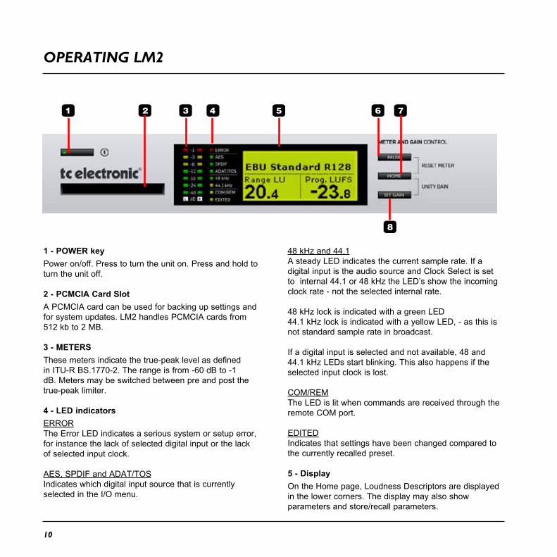
1 - POWER keyPower on/off. Press to turn the unit on. Press and hold to turn the unit off.
2 - PCMCIA Card SlotA PCMCIA card can be used for backing up settings and for system updates. LM2 handles PCMCIA cards from 512 kb to 2 MB.
3 - METERSThese meters indicate the true-peak level as defined in ITU-R BS.1770-2. The range is from -60 dB to -1 dB. Meters may be switched between pre and post the true-peak limiter.
4 - LED indicatorsERRORThe Error LED indicates a serious system or setup error, for instance the lack of selected digital input or the lack of selected input clock.
AES, SPDIF and ADAT/TOSIndicates which digital input source that is currently selected in the I/O menu.
48 kHz and 44.1A steady LED indicates the current sample rate. If a digital input is the audio source and Clock Select is set to internal 44.1 or 48 kHz the LED’s show the incoming clock rate - not the selected internal rate.
48 kHz lock is indicated with a green LED44.1 kHz lock is indicated with a yellow LED, - as this is not standard sample rate in broadcast.
If a digital input is selected and not available, 48 and 44.1 kHz LEDs start blinking. This also happens if the selected input clock is lost.
COM/REMThe LED is lit when commands are received through the remote COM port.
EDITEDIndicates that settings have been changed compared to the currently recalled preset.
5 - DisplayOn the Home page, Loudness Descriptors are displayed in the lower corners. The display may also show parameters and store/recall parameters.

OvERvIEw
6 - PAUSE keyPauses the loudness measurements. When engaged, the Home page reads “PAUSE” in the upper right-hand corner.
7 - HOME keyPress Home to toggle between the Home page and the Stats page. LM2 defaults to the Home page with the large Loudness Descriptors when not touched for 30 seconds.
When pressed together with neighbor keys, Home invokes these functions:
HOME + PAUSE: Resets all Loudness Descriptors and the Loudness Log.HOME + SET GAIN: Reverts LM2 to unity gain, resets the Loudness Descriptors and the Loudness Log.
The SET GAIN functions can be disabled on the I/O page. Factory presets with “Meter” in the title have SET GAIN functions disabled. Factory presets with “Ingest” in their title have SET GAIN functions enabled.
8 - SET GAINAdditional to metering, LM2 may perform static gain offsets in order for a program to comply with a certain Target level. Once a program has been measured, press the Set Gain key to have LM2 automatically apply the static gain required to make the program arrive precisely at Target level.
The Set Gain key also resets the Loudness descriptors and the Loudness log.
The Set Gain key may be enabled or disabled in the I/O menu. The key is disabled in all factory preset banks called “Meter” while it is enabled in all preset factory banks called “Ingest”.
9 - RECALL keyThe RECALL key recalls presets. Turn the ENCODER to select a preset, - then press ENTER.
10 - STORE keyPress STORE once to access Store mode. Then select store location using the ENCODER. Press ENTER to confirm.
OPERATINg LM2
11
OvERvIEwREAR PANEL
12
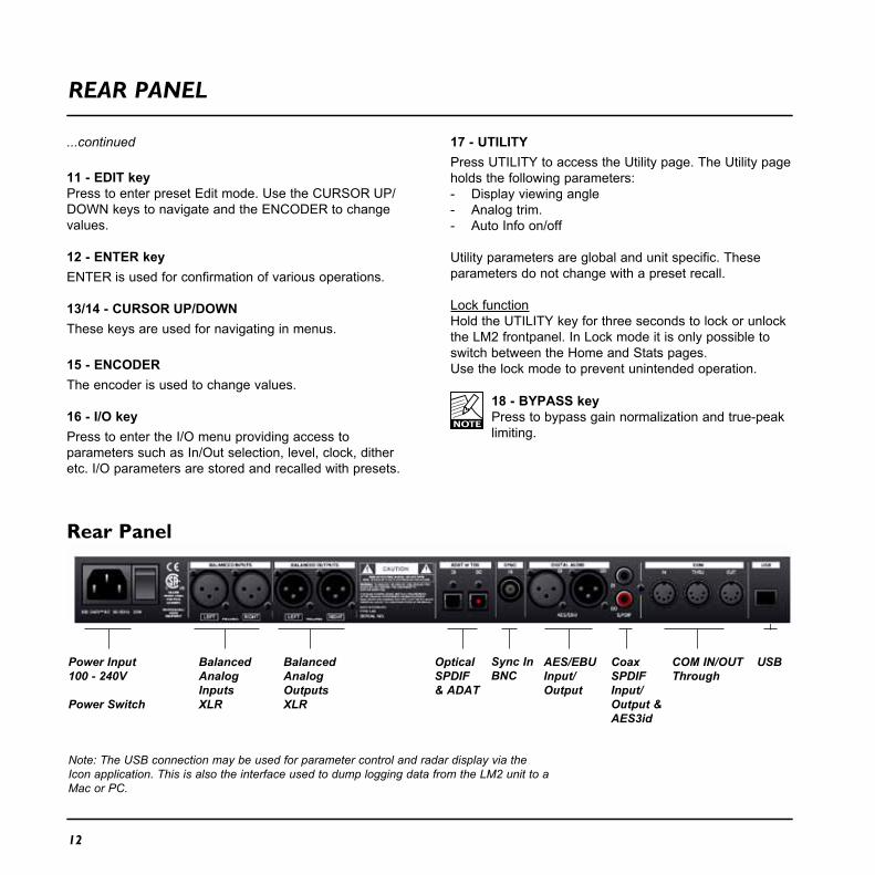
11 - EDIT keyPress to enter preset Edit mode. Use the CURSOR UP/DOWN keys to navigate and the ENCODER to change values.
12 - ENTER keyENTER is used for confirmation of various operations.
13/14 - CURSOR UP/DOWNThese keys are used for navigating in menus.
15 - ENCODERThe encoder is used to change values.
16 - I/O keyPress to enter the I/O menu providing access to parameters such as In/Out selection, level, clock, dither etc. I/O parameters are stored and recalled with presets.
BalancedAnalogInputsXLR
AES/EBUInput/Output
BalancedAnalogOutputsXLR
CoaxSPDIFInput/Output & AES3id
Power Input100 - 240V
Power Switch
USBCOM IN/OUT Through
OpticalSPDIF & ADAT
Note: The USB connection may be used for parameter control and radar display via the Icon application. This is also the interface used to dump logging data from the LM2 unit to a Mac or PC.
Sync InBNC
Rear Panel
...continued 17 - UTILITYPress UTILITY to access the Utility page. The Utility page holds the following parameters:- Display viewing angle - Analog trim. - Auto Info on/off
Utility parameters are global and unit specific. These parameters do not change with a preset recall.
Lock functionHold the UTILITY key for three seconds to lock or unlock the LM2 frontpanel. In Lock mode it is only possible to switch between the Home and Stats pages.Use the lock mode to prevent unintended operation.
18 - BYPASS keyPress to bypass gain normalization and true-peak limiting.
OvERvIEwTHE dISPLAy - HOME PAgE
13
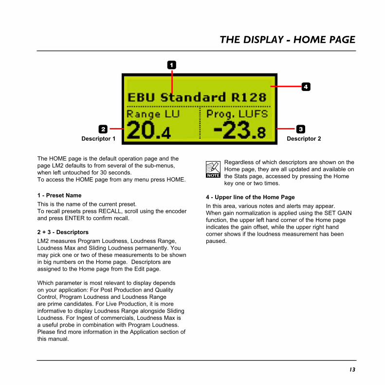
The HOME page is the default operation page and the page LM2 defaults to from several of the sub-menus, when left untouched for 30 seconds.To access the HOME page from any menu press HOME.
1 - Preset NameThis is the name of the current preset.To recall presets press RECALL, scroll using the encoder and press ENTER to confirm recall.
2 + 3 - DescriptorsLM2 measures Program Loudness, Loudness Range, Loudness Max and Sliding Loudness permanently. You may pick one or two of these measurements to be shown in big numbers on the Home page. Descriptors are assigned to the Home page from the Edit page.
Which parameter is most relevant to display depends on your application: For Post Production and Quality Control, Program Loudness and Loudness Range are prime candidates. For Live Production, it is more informative to display Loudness Range alongside Sliding Loudness. For Ingest of commercials, Loudness Max is a useful probe in combination with Program Loudness. Please find more information in the Application section of this manual.
Regardless of which descriptors are shown on the Home page, they are all updated and available on the Stats page, accessed by pressing the Home key one or two times.
4 - Upper line of the Home PageIn this area, various notes and alerts may appear. When gain normalization is applied using the SET GAIN function, the upper left hand corner of the Home page indicates the gain offset, while the upper right hand corner shows if the loudness measurement has been paused.
Descriptor 1 Descriptor 2

14
THE dISPLAy - HOME PAgE
Set Gain
Reset Meter
Pause
Set GainPress Set Gain to insert a gain offset before the loudness meter. This function is used for easy normalization of programs, and under the protection of LM2’s true-peak limiter. Set Gain may be disabled on the I/O page. Only Factory “Ingest” presets have the function enabled.
Example- Loudness Target level has been set to -23 LUFS
(EBU standard)- LM2 has measured a program to -35.8 LUFS- Press Set Gain and a gain of +12.8 dB is applied
When SET GAIN is active the applied gain, negative or positive is indicated in the upper left corner.
Attention - the Set Gain function resets measurement and logging
Set Gain may be used during transmission by an experienced operator, and pressed more than once. Each time Get Gain is pressed, output loudness will be re-aligned to match Target loudness. This may create level-jumps, but at a time of the operator’s choosing.
Reset MeterPress both the HOME and PAUSE buttons to reset metering. The display briefly indicates reset.
PauseFor easy reading at a specific time the metering can be paused by pressing the PAUSE button.Pause can also be used to exclude certain program material such as commercials from measurement , or to only measure, for instance, regular speech if so desired.
Start of a new measurementWhen LM2’s meter is reset by pressing Home and Pause, instead of numbers it shows “-” markings in the display. Two lines, “- -”, indicates that the measurement has been reset, and that no audio above the safety gate threshold (-70 LUFS) has yet been detected. One line, “-”, indicates that audio level above the safety gate has been detected and that it will influence the measurement. Once enough audio has been registered for it to be of statistical value, descriptor numbers appear.
Sliding Loudness does not show “- -” when the meter is reset. This is because Sliding Loudness is defined as a running measure without safety gate. If the level drops to -100 LUFS or lower, Sliding Loudness displays “-”.

15
OvERvIEw EdIT PAgE
Navigating the Edit page- press the EDIT key to enter the page- press CURSOR UP/DOWN keys to move cursor and use the ADJUST wheel to change parameter values- to access Edit page 2, place cursor at the parameter in the bottom of the display and press the CURSOR DOWN key- to exit the EDIT pages, press EDIT or HOME - or press e.g. UTILITY or I/O keys to navigate directly to those menus.LM2 automatically returns to the Home page after 30 sec if no key has been touched.
Parameters and settings
Descriptor 1 Loudn. Range, Prog. Loudn., Sliding Loudn., Loudn. Max, Off
Descriptor 2
Sliding Loudness From 3 sec to 8 minLoudness Max 0.4 sec to 10 sec
Lim Threshold TP -18 dB to offLim Profile Dynamic, AC3 Codec,
UniversalLoud, VoiceLim Link Off, On
Target -6 to -36.0 LUFS (if LUFS)Norm. Gain +/- 24 dBLoudness Unit LUFS, LU, LU/LUFSLoudness Std. EBU R128, ATSC A/85,
Cnt of Grav.
Page 1
Page 2
Page 3
The Edit page is used for selecting the Loudness Descriptors shown on the Home page, measurement standard, adjustment of normalizing gain, true-peak limiting etc. Note: Edit page parameters are stored and recalled with presets.

OvERvIEwEdIT PAgE
16
Descriptor 1-2Loudn. RangeLoudness Range, standardized in EBU R128 and abbreviated “LRA”, displays the loudness range of a program, a film or a music track. The unit is LU, which can be thought of as “dB on the average”.
The Loudness Range descriptor quantifies the variation of the loudness measurement of a program. It is based on the statistical distribution of loudness within a programme, thereby excluding the extremes. Thus, for example, a single gunshot is not able to bias the LRA number.
EBU R128 does not specify a maximum permitted LRA. R128 does, however, strongly encourage the use of LRA to determine if dynamic treatment of an audio signal is needed and to match the signal with the requirements of a particular transmission channel or platform.
Consequently, if a program has LRA measured at 10 LU, you would need to move the master fader +- 5 dB to make loudness stay generally the same over the duration of the program. (Not that you would want that).
In production, Loudness Range may serve as a guide to how well balancing has been performed, and if too much or too little compression has been applied. If a journalist or video editor isn’t capable of arriving at a suitable LRA, he could be instructed to call an audio expert for help.
This may be regarded as initial production guidelines:HDTV and digital radio: Stay below LRA of 20 LU.SDTV: Stay below LRA of 12 LU.Mobile TV and car radio: Stay below LRA of 8 LU.
Remember to use LRA the other way around too: If there is an ideal for a certain genre, check its LRA measure, and don’t try go below it. LRA should not be used for Limbo. Allow programs or music tracks the loudness range they need, but not more than they need.
Loudness Range may also be measured on a broadcast server to predict if a program is suitable for broadcast without further processing. LRA is even a fingerprint of a program and stays the same downstream of production if no dynamics processing has been applied. You may even check the number out of a consumer’s set-top box to verify that distribution processing and Dolby DRC has been disabled.
Like with Program Loudness and Loudness Max, the meter should be reset before measuring LRA.
Prog. Loudn.Program Loudness returns one loudness number for an entire program, film or music track. Its unit is LUFS. Some vendors and countries use the unit “LKFS” or “LFS”, but all three are the same: An absolute measure of loudness in the digital domain, where the region around “0” is overly loud and not relevant for measuring anything but test signals. Expect readings of broadcast programs in the range between -28 and -20 LUFS.
Program Loudness is used as a production guideline, for transparent normalizing of programs and commercials, and to set loudness metadata in delivery if so required. For delivery or transmission of AC3 format, the metadata parameter “dialnorm” should reflect Program Loudness. The easiest way to handle multiple broadcast platforms is to normalize programs at the station to a certain value, thereby being able to take advantage of the normalization benefits across platforms, at the same time enabling static metadata.
Loudness measurements in LM2 are all rooted in ITU-R BS.1770-2. However, subtle differences exist between different regions of the world. Therefore LM2 also includes the “Loudness Standard” parameter. Be sure to set this parameter correctly for compliance in your region.
The Program Loudness target is more or less the same for broadcasters around the world, especially when

17
EdIT PAgE
17
taking the measurement differences into account. Target numbers range between -24 and -22 LUFS.
Like with Loudness Range and Loudness Max, the meter should be reset before measuring Program Loudness.
Sliding Loudn.Sliding Loudness, unlike Program Loudness, Loudness Range and Loudness Max, is a continuously updated measure that doesn’t need to be reset. This type of descriptor is especially useful when “mixing by numbers”, i.e. when there is no access to the extremely informative radar display. When mixing by numbers, having Program Loudness as one descriptor and Sliding Loudness as the other displays simultaneous information about the full program side by side with the most recent loudness history.
The Edit menu includes a separate parameter where the width of the sliding window may be defined. For typical broadcast production, a starting point between 6 and 15 seconds is suggested. For production of commercials or promos, 3 or 6 seconds would should be considered, while longer duration wide loudness range production (drama, acoustic music) might give more relevant numbers with a duration of 30 seconds or longer.
Note 1: Because the Sliding Loudness measurement is completely un-gated, it may also be used to spot check sections of a program complying to “raw” ITU-R BS.1770-2 and the first revision of ATSC A/85.
Note 2: LM2 makes use of optimized statistics processing in order to display a sliding loudness value (a prognosis) as quickly as possible after a reset. Until the sliding window has been filled, a spinning line symbol is shown next to the descriptor title.
Loudness MaxLoudness Max displays the maximum loudness registered since the meter was last reset. Loudness Max is an especially useful parameter when checking and
normalizing short duration programs such as promos and commercials. BCAP rules from the UK is an example of using Loudness Max as an efficient instrument to reduce listener complaints regarding loud commercials. While Program Loudness is adequate to normalize a consistent mix, Loudness Max may be used as a second line of transparent defense against overly short and loud event.
The Edit menu includes a separate parameter where the width of the Loudness Max window may be defined. Experience from the UK indicates that a Loudness Max width of 3 or 4 seconds should be used for such a purpose.
TargetRange: -36 LUFS to -6 LUFS
The parameter specifies the loudness level to generally aim at. It affects a number of functions and displays in LM2, and must be set according to the standard you need to comply with. Current broadcast standards require Target to be in the range between -26 and -20 LUFS. For instance, EBU R128 calls for -23 LUFS while ATSC A/85 specifies -24 LUFS.
The Target parameter affects these LM2 functions and displays:
1. Target sets the reference point for loudness measurements in LU. If the Loudness Unit parameter is set to LU, Program Loudness, Sliding Loudness and Loudness Max will be shown in LU relative to Target. On Target measurements will consequently read “0.0 LU”.
2. Target defines the aim for LM2’s normalization functions. When the Set Gain key is pushed, LM2 inserts a gain equalling the difference between Program Loudness and Target. For instance, if Target is set to -23.0 LUFS and Program Loudness measures -21.5 LUFS, LM2 inserts a gain of -1.5 dB.

18
EdIT PAgE
3. Target defines the “12 o’clock” value of the Radar meter when LM2 is connected to a Mac or a PC running the Icon application.
Loudness UnitLUFSAll measurements of program loudness and sliding loudness are shown in units of LUFS, that is, in Loudness Units on the absolute scale. This is the normal setting for the Loudness Unit parameter, that we recommend for most applications.Loudness Range is always shown in units of LU, because it is basically a measurement of ‘range’ or of the distance between a high and a low loudness level.
LUFS/LUThis setting is similar to the ‘LUFS’ setting, except that the Radar display uses an LU scale rather than an LUFS scale, on the Icon. There is no difference between the LUFS and LU/LUFS settings, when the LM2 is used in stand-alone mode.
LUIn this setting, measurements of program loudness and sliding loudness are shown in units of LU, that is, in Loudness Units on a relative scale. The 0 LU is by definition the target loudness level, such as -23.0 LUFS. So by selecting ‘LU’, one can immediately see if a loudness level is above the target level (e.g. +1.2 LU) or below (e.g. -3.4 LU).
Loudness Std.Options: BS.1770-2, Leq(K) or Cnt of Grav.The Program Loudness measure is always rooted in the ITU-R BS.1770 loudness model. This parameter sets measurement gating. Note that the parameter only
influences Program Loudness, and not Sliding Loudness or Loudness Max.
BS.1770-2This setting reflects the latest revision of ITU-R BS.1770.Relative gate at -10 LU, safety gate at -70 LUFS.
Leq(K)This setting reflects the original version of ITU-R BS.1770.No measurement gate besides from at safety gate at -70 LUFS, so the user doesn’t need to precisely start and stop a measurement in order to avoid bias from complete silence.
Cnt of Grav.The standard setting from early versions of TC radar meters.Relative gate at -20 LU, safety gate at -70 LUFS.
International StandardsNote how the three Loudness Standard settings generally return the same Program Loudness result for Narrow Loudness Range (“NLR”) programs, such as commercials and pop music, but can differ significantly with Wide Loudness Range (“WLR”) programs such as film, drama, acoustical music etc.
For an update on international standards, check for new versions of this manual, or download the Loudness Glossary available at www.tcelectronic.com/loudness
This is the situation as of August, 2011:Japan, Canada, Brazil, China, Europe and most other countries specify the use of BS.1770-2 to make Program Loudness perform well across genres. BS.1770-2 enables the meter reliably to focus on foreground sound, and to transparently control loud commercials. ARIB (Japan) specifies BS.1770-2 in TR-B32. EBU (Europe) specifies BS.1770-2 in EBU R128 and in associated Tech Doc 3341.

19
EdIT PAgE
Target Level in these countries is -23 LUFS or -24 LUFS, measurement gating at -10 LU.
United States. Page 11 of ATSC A/85 (May 25, 2011) references ITU-R BS.1770-1, even though BS.1770-2 was in effect at that time. The same page also says that “All referenced documents are subject to revision”. The wording is ambiguous and it’s up to the reader to decide whether or not a relative gate (the difference between BS.1770-1 and BS.1770-2) is applied when measuring Program Loudness. The “Leq(K)” setting in LM2 disables the relative gate, while the setting “BS.1770-2” includes a relative gate at -10 LU. The BS.1770-2 setting is better across genres and for controlling loud commercials. Check in at www.atsc.org to see if the CALM act has forced ATSC to make up their mind.
Target Level in United States is -24 LUFS, measurement gating not clearly defined.
LimiterLM2 includes a true-peak limiter and 48 bit internal precision. Limiter Threshold sets the max true-peak level on LM2’s outputs. In case positive normalization is invoked, the limiter comes into action when the peak level could otherwise have created an overload.
Profiles: Dynamic, AC3 Codec, Universal, Loud, Voice.The adaptive Profiles allow you to tell The Limiter what your intentions are. Several internal variables are dynamically updated based on the Profile chosen, so distortion is perceived (and measured) to be as low as possible for a given loudness, and reduction in average/peak ratio. Maximum perceived distortion tolerated is different from Profile to Profile. The multi-dimensional parameter-space is fully continuos toavoid situations where distortion could occur, or where processing is suddenly altered without a detectable cause. Acquaintance yourself with the different Profiles to have them at hand when called for by a specific application.
The Dynamic Profile offers gentle processing with minimum static and dynamic distortion. It’s a first choice for audiophile limiting, for instance with classical music, choir etc.
The AC3 Codec profile has been optimized for protecting the relatively sensitive AC3 codec, which was invented before squeeze-box techniques in production had proliferated. When used for stereo, there are no down-mix issues with the codec, and the threshold of the true-peak limiter can safely be set to -2 dBFS or -1 dBFS.
The Universal Profile has a higher tolerance for perceived distortion than Dynamic. It is still magnitudes better than analog designs, but may be on the aggressive side for sensitive music. It is a good choice for starters, and in production where you don’t know what to expect.
The Loud Profile again has a higher tolerance for perceived distortion, and is therefore better suited for production and mastering rather than live applications.
The Voice Profile is targeted human voice, and adapts well to asymmetrical signals. Used on composite material, perceivable distortion is to be expected with large ratios of limiting.
Limiter ThresholdRange: -18 dB to offLM2’s limiter employs a look-ahead delay of 0.6 ms and complies with ITU-R BS.1770-2 true-peak specifications. Because true-peak limiting is a better strategy from an audio quality point of view than sample-peak limiting, and because LM2 has an immense internal headroom, there is generally no need to set the limiter threshold lower than -1 dBFS. However, if the downstream path contains low bit-rate codecs or emphasis/de-emphasis circuitry, the limiter threshold may need to be set considerably lower. To enable pristine audio quality, the limiter threshold should not be set lower than needed for a certain broadcast platform. Also notice how you may be able to lift the limiter threshold over time as a distribution path improves.

20
I/O PAgE
Navigating the I/O page- press the I/O key to enter the page- press CURSOR UP/DOWN keys to move cursor and use the ADJUST wheel to change parameter values- to access I/O page 2, place cursor at the parameter in the bottom of the display and press the CURSOR DOWN key- to exit the EDIT pages, press EDIT - or press UTILITY or EDIT keys to navigate directly to those menus.LM2 automatically returns to the Main page after 30 sec if no key has been touched.
The I/O page is used for selecting I/O formats, clock conditions, scaling of AD and DA converts, disabling of the Set Gain function etc. Note: I/O page parameters are stored and recalled with presets.
Parameters and settings
Input Select AES, SPDIF, TOS, ADATAnalog
Clock Select Intern. 44.1/48 kHzDigital In, Word Clock,
ADAT Input ADAT 1/2, 3/4, 5/6, 7/8Optical Output TOS, ADAT 1/2, 3/4, 5/6, 7/8 Set Gain Disabled/Enabled
TP Meter Pre Lim/Post Lim
Ana In, FS@ +6 to +21 dBuAna Out, FS@ +6 to +21 dBuAna Fader Off, -119 dB to +12 dBDither Off, 24, 20,16 bit
Page 1
Page 2
Page 3

21
I/O PAgE
Ana In FS@This parameter sets the gain in the analog domain before the A to D converter. It optimizes the use of the converter dynamic range like optical zoom on a digital camera. For precise analog measurements, where component tolerances of individual LM2 units, cable load etc. can be taken into account, this setting may be fine-tuned on the Utility page using the Ana In Trim parameters.
Ana Out FS@This parameter sets the gain in the analog domain after the D to A converter. It optimizes the signal/noise ratio when connecting, for example, active monitor speakers to the analog outputs of LM2. Used for this purpose, there should be only a couple of dB more headroom in LM2 than in the active speaker. The headroom adjustment should be done with the Ana Fader parameter set to 0.0 dB. When the speaker clips, LM2’s analog output should be roughly 3 dB from clipping too.
Ana FaderThis parameter sets the gain in the digital domain before the D to A converter. Its primary use is to enable calibrated monitoring. The setup of calibrated monitoring should be performed in this sequence: 1) Scale the analog output using the Ana Out FS@
parameter. 2) Feed a pink noise reference signal to a digital input of
LM2. 3) Adjust the Ana Fader parameter to obtain the desired
sound pressure level at mixing position from each speaker one at a time.
4) Store the preset for easy access to a certain calibrated SPL.
Clock selectFor analog input source select between:Internal 44.1 kHz or Internal 48 kHzIf an external clock is connected to the AES or Word Clock input, one of those may also be used as a reference for LM2”
For digital input source select between:Digital In, Wordclock (Intern at 44.1 kHz, Intern at 48 kHz).
Input and Clock selections must be performed carefully to ensure synchronous precision performance from LM2.
Example:Input Source: AES (48 kHz)Clock Select: Internal 48 kHz
This situation could cause sample slips and the recommended settings would be:
Input Source: AES (48 kHz)Clock Select: Digital in.
If Word Clock is used as master clock for the digital source it could also be used as clock for LM2. Connect Word Clock to Sync. In and set Clock Select to Word Clock.

PAgE HEAd
22
UTILITy PAgE
Navigating the Utility page- press the UTILITY key to enter the page- press CURSOR UP/DOWN keys to move cursor and use the ADJUST wheel to change parameter values- to exit the UTILITY page, press EDIT - or press I/O or EDIT keys to navigate directly to those menus.LM2 automatically returns to the Main page after 30 sec if no key has been touched.
UTILITY parameters are global (not part of presets).
Viewing AngleAdjust for best viewing comfort of the LM2 display
Analog Trim L + R+/- 1 dB level adjust for trim in steps of 0.01 dB
Auto InfoTurn this function on to make LM2 automatically generate preset comments when stored. The information is shown at the bottom of the front panel display during preset recall, and below the preset title if you recall using the Icon application. The auto function inserts the word “Meter” when the preset contains no gain offset and the Set Gain key is disabled. In other cases, the word “Normalize” is inserted. The auto function also includes information about the input selected.
The Utility pages is used for setting unit specific parameters such as display viewing angle, converter trimming etc. Note: Utility page parameters are global and not stored or recalled with presets.

23
STATS PAgE
The Stats page provides an overview of key parameters. Press the HOME key at any time to enter the Stats pages and see; Program Loudness, Loudness Max, Loudness Range and True-Peak Max.

24
PAgE HEAdPRESET HANdLINg
Preset RecallFactory presets, User presets and PCMCIA presets may be recalled from LM2’s front panel, or using the Icon application. The User preset bank may be copied to a computer or overwritten using the Library/Bank page of the Icon application.
On the store and recall pages, preset banks are located in the following order:
1 Factory Presets (Locally stored on the LM2, and never overwritten) Factory presets are divided into groups of up to 8 presets each.
2 User Presets (Locally stored on the LM2)
3 Presets on a PCMCIA card
- Press Recall to ensure you are at the Recall Page.- Select the preset you wish to recall using the encoder.- Press ENTER.
Preset StorePresets can be stored in any of the 99 user locations and presets can be named individually. Navigate using the UP/DOWN keys and the encoder.
- Press STORE to enter store mode. - Select Location - where to store.- Select Mode - Overwrite/Delete.- Set/Change name.
ModeSelect between Overwrite and Delete.
OverwriteStandard storing method. The preset at the location where you attempt to store will be overwritten.
DeleteUse this function to delete presets without storing a new one at the same time.Consider this a “Clean-up” function.
Locat. - LocationSelect a user location where you wish to store the preset.With a standard PCMCIA card an additional 99 presets can be stored.(If used in conjunction with a TC Icon PC Editor an unlimited number of presets can be stored on your computers hard drive).
NameTo enter or alter a preset name during storing procedure:
- Set cursor at the “Name-line”.- Use the encoder wheel to change letter.- Use ARROW UP/DOWN to jump between letter positions.- Press ENTER to store and confirm.

PAgE HEAd
2525
TC ICON & LM2
All functions of LM2 work perfectly without a Mac or PC, but it may project more details on a computer display. Connect a Mac, a PC or TC Icon MKII via USB to gain access to the unique radar loudness meter. If a connection is established this way at least once per week, you may dump a detailed log covering full 24/7 operation.All parameters controllable from the front of the LM2 can of course also be set and adjusted via the TC Icon.
TC Icon Editor InstallationThe TC Icon Software Editor for PC and Mac is a fully operational software version of the TC Icon Remote. The software is free to download via www.tcelectronic.com
Acquiring the TC Icon EditorFind the TC Icon Editor on the supplied CD or download latest version www.tcelectronic.com/softwareYou will find a version for both Mac and PC
Installation - PCSystem Requirements- Windows 2000, NT, XP, Vista or 7- 1 GB RAM- INTEL/AMD 1.66GHz or higher- Open the zip-file- Open the cab-file- Copy the Icon file to your desktop (or another location)
Driver installation (PC only)Install the driver BEFORE connecting the LM2!
A driver installation application called “setup.exe” is found on the supplied CD and latest version is always available for download via www.tcelectronic.com/software.Click on the setup.exe file and follow the instructions. THEN connect the LM2.
Manual installation of the driver- if you connected the LM2 before running the driver installation application, Windows detects new hardware and the drivers can be installed from the CD.
BasicsNavigating the TC Icon Software Editor is easy as soon as a few basic elements are explained.
Generally:• Press the top-tabs to do primary selections.• Press the side-tabs or elements to do secondary
selections• Press parameter value fields to instantly assign
parameters to Fader 6• Adjust values using Faders 1-6• The TC Icon symbol key in the upper left corner
switched between two main modes: - Setup/Select pages for main system operations and - Operation pages that are specific for the connected
units
Unpacked and ready• Install software• Power up the LM2 and start the TC Icon software on
your computer• Go to the Setup/Devices/Select page
Installation - MacSystem Requirements- OSX 10.4, 10.5, 10.6- Power PC or Intel Mac- Stuffit Expander installed- Open the Icon.dmg file placed on your desktop and drag the application to your desktop or another location of your choice
Basic operation of the TC Icon Software Editor
26
LM2 & TC ICON
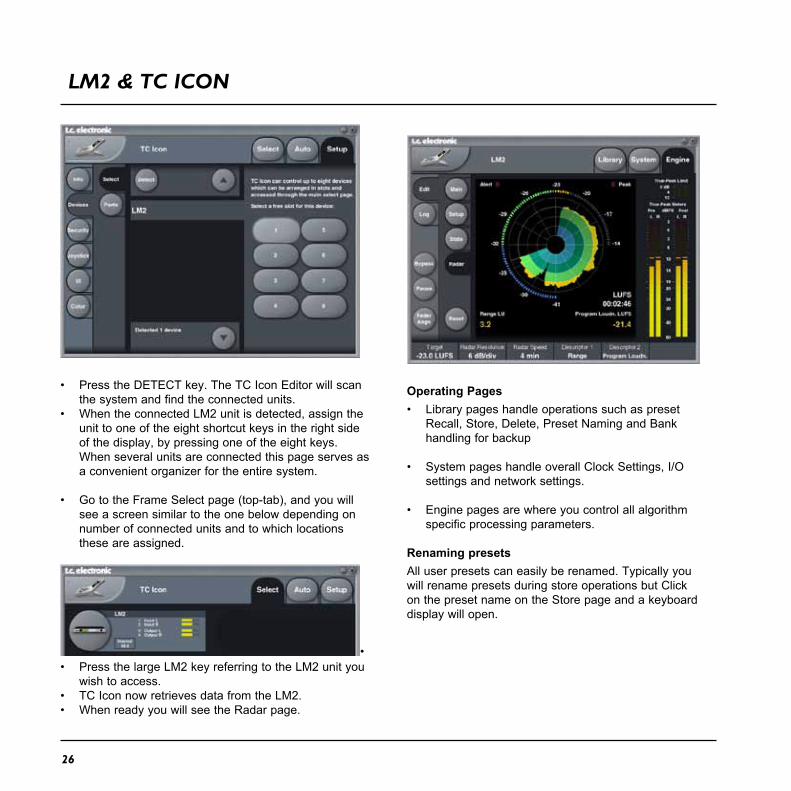
• Press the DETECT key. The TC Icon Editor will scan the system and find the connected units.
• When the connected LM2 unit is detected, assign the unit to one of the eight shortcut keys in the right side of the display, by pressing one of the eight keys.
When several units are connected this page serves as a convenient organizer for the entire system.
• Go to the Frame Select page (top-tab), and you will see a screen similar to the one below depending on number of connected units and to which locations these are assigned.
•• Press the large LM2 key referring to the LM2 unit you
wish to access.• TC Icon now retrieves data from the LM2.• When ready you will see the Radar page.
Operating Pages• Library pages handle operations such as preset
Recall, Store, Delete, Preset Naming and Bank handling for backup
• System pages handle overall Clock Settings, I/O settings and network settings.
• Engine pages are where you control all algorithm specific processing parameters.
Renaming presetsAll user presets can easily be renamed. Typically you will rename presets during store operations but Click on the preset name on the Store page and a keyboard display will open.
27
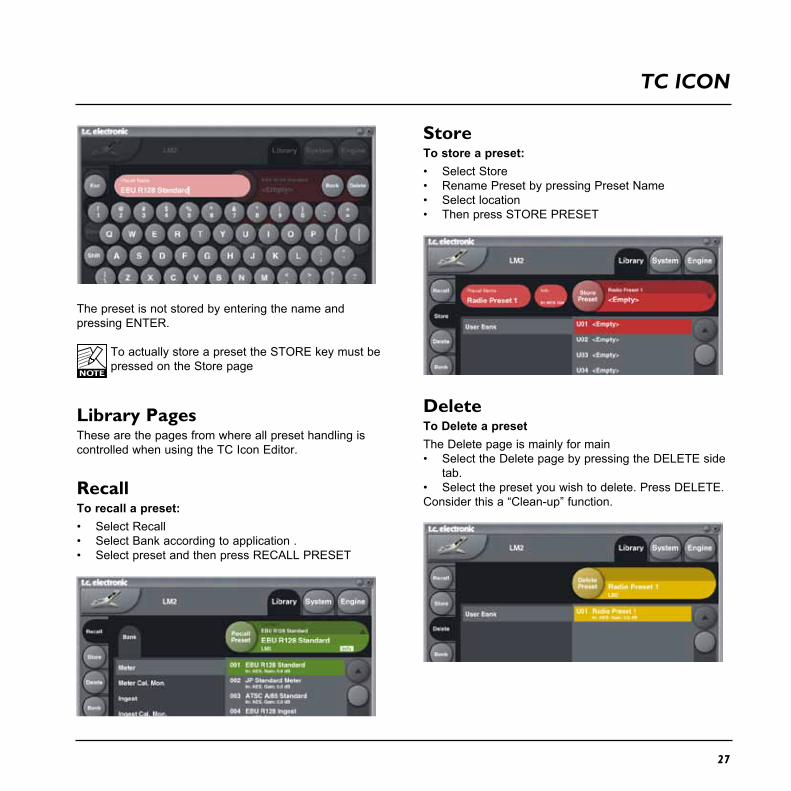
StoreTo store a preset:• Select Store• Rename Preset by pressing Preset Name• Select location• Then press STORE PRESET
DeleteTo Delete a presetThe Delete page is mainly for main• Select the Delete page by pressing the DELETE side
tab.• Select the preset you wish to delete. Press DELETE.Consider this a “Clean-up” function.
The preset is not stored by entering the name and pressing ENTER.
To actually store a preset the STORE key must be pressed on the Store page
Library Pages These are the pages from where all preset handling is controlled when using the TC Icon Editor.
RecallTo recall a preset:• Select Recall• Select Bank according to application .• Select preset and then press RECALL PRESET
TC ICON

28
TC ICON
Bank HandlingVia the Library Bank page it is possible to backup and retrieve the User bank either to your hard disk or to a PCMCIA card.
From BankIn this area you select which LM2 preset bank you wish to copy from.
From File If you have already stored banks on your computer this is where these files will appear.
To BankSelect to which LM2 bank you wish to copy the selected bank to.
To FileSelect “To File” if you wish to back-up the selected bank to your hard disk.
The TC Icon saves the bank files in a specific location. The location varies slightly between the different operation systems.
As an example Windows XP saves backup files in: C:\Documents and Settings\XX\Application Data\TC Electronic\TC Icon\LM2 Presets
(Note XX is the user name)
Do not move the files from this location or the TC Icon will not display the presets in the “From File” screen.
RenamePress to rename the selected bank.
DeletePress to delete the selected bank.

29
LM2 & TC ICON
Main page
The parameters on the Main page are described previously in the manual.

30
LM2 & TC ICON
Setup page
Momentary RangeSets the range of the outer ring in the Radar meter.Select between EBU +9 dB or EBU +18 dB.
Radar speedSets the duration of each radar revolution. Select from 1 minute to 24 hours. You may “zoom” between the settings, as long as the history isn’t reset. Pressing the
“X” key, or changing the Time Reference, resets the meter and descriptor history.
Radar resolutionSets the difference in loudness between each concentric circle in the Radar between 3 and 12 dB. Choose low numbers when targeting a platform with a low dynamic range tolerance. You may “zoom” between the settings, as long as the history isn’t reset. Pressing the “X” key,
31
LM2 & TC ICON
or changing the Time Reference, resets the meter and descriptor history.
Low Level BelowDetermines where the shift between green and blue happens in the outer ring. It indicates to the engineer that level is now at risk of being below the noise floor.
Alert IndicatorRange: Off/Stereo IntegrityThe Alert indicator is located on the Radar page and indicates suspected lack of stereo integrity based on measuring the difference of left/right outputs. If an average difference of 3 dB or more between left and right channels is meassured over a prolonged time, the LED is lit.
More alert functions may become available with new versions of LM2 software
Peak IndicatorThis parameter sets at which level the peak indicator will be invoked.
The remaining parameters are described earlier in this manual.

32
TC ICON & LM2
Stats Page
The Stats page gives an overview of essential parameters. Compared to the STATS page on the LM2 front, the TC Icon Stats page also holds the Sliding Loudness parameter.
Note! The Reset button resets the meters and the log file.

33
LM2 & TC ICON
Radar Page
The Radar page makes use of a unique way of visualizing short-term loudness, loudness history, and long-term statistical descriptors. It may be used with mono and stereo material for any type of program material.Press the “Radar” key to bring up the Radar page. This page will probably be used most of the time.
Note! The Reset button resets the meters and the log file.
Target Loudness is displayed at 12 o’clock of the outer ring, and at the bold, concentric circle of the radar. The Universal Descriptors, Consistency and Center of Gravity, are the yellow numbers in the lower part of the display. Press RESET to reset Radar and Descriptors.

34
RAdAR PAgE
Meter ResetPlease notice that the meter will be reset and the history/log-file is deleted in the following situations.
Power on off- turning of the LM2, Either from the front or the back, will reset the meter.
Reset- resetting the meter from the front by holding HOME and PAUSE pressed simultaneously, - or resetting the meter from the TC Icon Editor
Set Gain- activating the Set Gain function either from the front or via the TC Icon Editor
Recall- recalling a preset either from the front or via the TC Icon Editor
Selecting Loudness Standard- selecting a different Loudness model via the Edit page or vi the TC Icon Editor.

35
USINg MULTIPLE LM2’S
Up to 8 LM2’s can be conveniently controlled and monitored by a single TC Icon Editor. You can switch between and access each frame via the Select page. Log files can be stored in the same or different folders convenient tracking of each unit.

36
LOggINg
24/7 LoggingAs a standard feature LM2 comes with hindsight: the radar can show the past 24 hours, but LM2 actually includes so much memory of its own that you can take a detailed look one week back in time, even if it has had no connection to a computer. Dump log files routinely to PC or Mac and design graphing showing history etc. in Excel.(see guide on the following pages).
Log File FolderEnter the path where you want the logging files saved.Default folder PC; C:\Documents and Settings\XX\Application Data\TC Electronic\TC Icon\LM2 PresetsDefault folder Mac; /Users/XX/Documents/TC Icon Data/LM2 Presets- where XX is the users name.
Device IDSeveral LM2 units can be controlled via a single Icon Editor. Consider the Device ID as a label for the LM2. Per default the Device ID is the LM2 units serial number.The Device ID is clearly indicated in the logging file and typical use could be using this ID to refer to the processed signal - e.g. “TV1”, “Radio 1” etc.
Device ID is NOT the same as the Network Identifier found on the System Net page.The Network Identifier is used for easy identification in a network of TC Electronic devices.
Dump LogPress to dump the LOG file to the specified location.
Show Log Header For overview of the stored logs the Log header can be displayed using the “Show Log Header” function.
Example:

37
LOggINg
Loss of Log fileIt is important to notice the following situations that will cause the loss of the current LM2 log file.
- Turning off the LM2 using the power switch on the rear panel
- Disconnecting the power cable
If the device cannot be detected we therefore recommend trying the following steps before switching off the unit.
First, try to re-detect the device: Setup/Devices/Detect.If that doesn’t work, try to close and reopen the Icon application. As a third option try to detach the USB cable and wait 10 seconds before reattaching it.
Depending on needs/convenience 2 more options are available. - try a FULL reboot of the PC- try a FULL power OFF/ON, using the physical on/
off switch on the back of LM2. Wait 10 seconds from OFF to ON.
Note that you loose the Loudness Log File stored in the unit during this operation. See also the previous page “Meter Reset” describing other situations invoking loss of log file.
Viewing Log file dataThe Log file data can be viewed as text using e.g. Notepad (PC) or TextEdit (Mac).
By using Microsoft Excel or Mac iWorks Numbers the history Log file can be viewed graphically.
Procedure for importing data in MS Excel (Mac+PC)(the illustrations below are from a PC but the procedure is identical on Mac)
- In the dialog “Open” (Ctrl+O) select “All files” in File-Types
- Select the LM2 log file and click “Open”- Select “Delimited”
- Click “Next”- Select “Tab” as Delimiter and press “Next”
- in Columns Data format select “General”
- press “Advanced” and select “.” as Decimal separator. DO NOT SELECT “,” !
- Press “OK” and “Finish”
You have now imported the data. You may need to adjust column width etc. for better viewing.
38
LOggINg
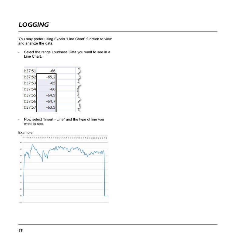
You may prefer using Excels “Line Chart” function to view and analyze the data.
- Select the range Loudness Data you want to see in a Line Chart.
- Now select “Insert - Line” and the type of line you want to see.
Example:

39
SETUP ExAMPLES - PROdUCTION
Fig 2Production meter extended with Radar.Use a preset from the Meter bank.
Fig 1Stand-alone Production meter for “mixing by numbers”.Use a preset from the Meter bank.

SETUP ExAMPLES - PROdUCTION
40
Fig 3Calibrated stereo listening added to metering.Use a preset from the Meter Cal. Mon. bank.
Fig 4Calibrated listening for multiple sets of speakers and headphones added to metering.Use a preset from the Meter bank.

41
SETUP ExAMPLES - INgEST
Fig 5Meter and gain normalize for broadcast Ingest and QC.Use a preset from the Ingest bank.
Fig 6Meter, gain normalize and calibrated monitoring for broadcast Ingest and QC.Use a preset from the Ingest Cal. Mon. bank.
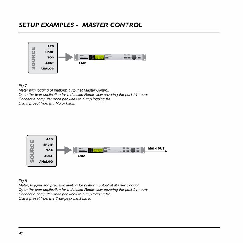
SETUP ExAMPLES - MASTER CONTROL
42
Fig 7Meter with logging of platform output at Master Control.Open the Icon application for a detailed Radar view covering the past 24 hours.Connect a computer once per week to dump logging file.Use a preset from the Meter bank.
Fig 8Meter, logging and precision limiting for platform output at Master Control.Open the Icon application for a detailed Radar view covering the past 24 hours.Connect a computer once per week to dump logging file.Use a preset from the True-peak Limit bank.

4343
SETUP ExAMPLES - LOggINg
Fig 9Gather logs from strategical consumer locations post transmission and post distribution.

44
SIgNAL fLOw dIAgRAM
45
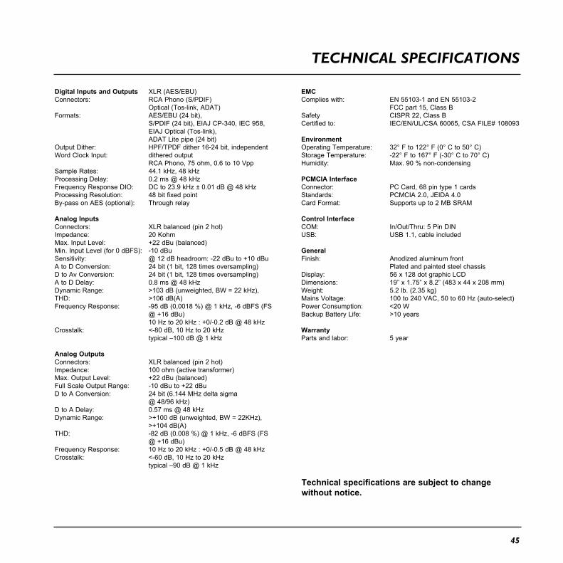
Digital Inputs and OutputsConnectors:
Formats:
Output Dither:Word Clock Input:
Sample Rates:Processing Delay:Frequency Response DIO:Processing Resolution:By-pass on AES (optional):
Analog InputsConnectors:Impedance:Max. Input Level:Min. Input Level (for 0 dBFS):Sensitivity:A to D Conversion:D to Av Conversion:A to D Delay:Dynamic Range:THD:Frequency Response:
Crosstalk:
Analog OutputsConnectors:Impedance:Max. Output Level:Full Scale Output Range:D to A Conversion:
D to A Delay:Dynamic Range:
THD:
Frequency Response:Crosstalk:
XLR (AES/EBU)RCA Phono (S/PDIF)Optical (Tos-link, ADAT)AES/EBU (24 bit),S/PDIF (24 bit), EIAJ CP-340, IEC 958,EIAJ Optical (Tos-link),ADAT Lite pipe (24 bit)HPF/TPDF dither 16-24 bit, independent dithered outputRCA Phono, 75 ohm, 0.6 to 10 Vpp44.1 kHz, 48 kHz0.2 ms @ 48 kHzDC to 23.9 kHz ± 0.01 dB @ 48 kHz48 bit fixed pointThrough relay
XLR balanced (pin 2 hot)20 Kohm+22 dBu (balanced)-10 dBu@ 12 dB headroom: -22 dBu to +10 dBu24 bit (1 bit, 128 times oversampling)24 bit (1 bit, 128 times oversampling)0.8 ms @ 48 kHz>103 dB (unweighted, BW = 22 kHz), >106 dB(A)-95 dB (0,0018 %) @ 1 kHz, -6 dBFS (FS @ +16 dBu)10 Hz to 20 kHz : +0/-0.2 dB @ 48 kHz<-80 dB, 10 Hz to 20 kHztypical –100 dB @ 1 kHz
XLR balanced (pin 2 hot)100 ohm (active transformer)+22 dBu (balanced)-10 dBu to +22 dBu24 bit (6.144 MHz delta sigma @ 48/96 kHz)0.57 ms @ 48 kHz>+100 dB (unweighted, BW = 22KHz), >+104 dB(A)-82 dB (0.008 %) @ 1 kHz, -6 dBFS (FS @ +16 dBu)10 Hz to 20 kHz : +0/-0.5 dB @ 48 kHz<-60 dB, 10 Hz to 20 kHztypical –90 dB @ 1 kHz
EMCComplies with:
SafetyCertified to:
EnvironmentOperating Temperature:Storage Temperature:Humidity:
PCMCIA InterfaceConnector:Standards:Card Format:
Control InterfaceCOM:USB:
GeneralFinish:
Display:Dimensions:Weight:Mains Voltage:Power Consumption:Backup Battery Life:
WarrantyParts and labor:
EN 55103-1 and EN 55103-2FCC part 15, Class BCISPR 22, Class BIEC/EN/UL/CSA 60065, CSA FILE# 108093
32° F to 122° F (0° C to 50° C)-22° F to 167° F (-30° C to 70° C)Max. 90 % non-condensing
PC Card, 68 pin type 1 cardsPCMCIA 2.0, JEIDA 4.0Supports up to 2 MB SRAM
In/Out/Thru: 5 Pin DINUSB 1.1, cable included
Anodized aluminum frontPlated and painted steel chassis56 x 128 dot graphic LCD19” x 1.75” x 8.2” (483 x 44 x 208 mm)5.2 lb. (2.35 kg)100 to 240 VAC, 50 to 60 Hz (auto-select)<20 W>10 years
5 year
Technical specifications are subject to change without notice.
TECHNICAL SPECIfICATIONS
