taylor aparat za sladoled
TRANSCRIPT

Models C708 & C716
Heat TreatmentSoft Serve Freezer
Operating Instructions
059061--M6/17/08
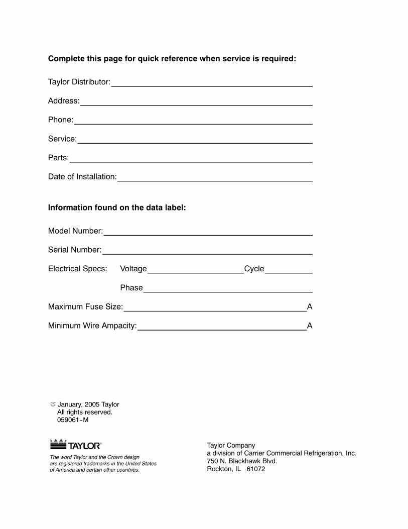
Complete this page for quick reference when service is required:
Taylor Distributor:
Address:
Phone:
Service:
Parts:
Date of Installation:
Information found on the data label:
Model Number:
Serial Number:
Electrical Specs: Voltage Cycle
Phase
Maximum Fuse Size: A
Minimum Wire Ampacity: A
E January, 2005 TaylorAll rights reserved.059061--M
The word Taylor and the Crown designare registered trademarks in the United Statesof America and certain other countries.
Taylor Companya division of Carrier Commercial Refrigeration, Inc.750 N. Blackhawk Blvd.Rockton, IL 61072
Models C708 & C716 Table of Contents
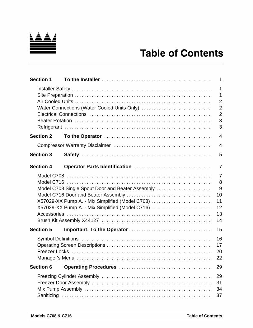
Table of Contents
Section 1 To the Installer 1. . . . . . . . . . . . . . . . . . . . . . . . . . . . . . . . . . . . . . . . . . . .
Installer Safety 1. . . . . . . . . . . . . . . . . . . . . . . . . . . . . . . . . . . . . . . . . . . . . . . . . . . . . . . .Site Preparation 1. . . . . . . . . . . . . . . . . . . . . . . . . . . . . . . . . . . . . . . . . . . . . . . . . . . . . . .Air Cooled Units 2. . . . . . . . . . . . . . . . . . . . . . . . . . . . . . . . . . . . . . . . . . . . . . . . . . . . . . .Water Connections (Water Cooled Units Only) 2. . . . . . . . . . . . . . . . . . . . . . . . . . . .Electrical Connections 2. . . . . . . . . . . . . . . . . . . . . . . . . . . . . . . . . . . . . . . . . . . . . . . . .Beater Rotation 3. . . . . . . . . . . . . . . . . . . . . . . . . . . . . . . . . . . . . . . . . . . . . . . . . . . . . . .Refrigerant 3. . . . . . . . . . . . . . . . . . . . . . . . . . . . . . . . . . . . . . . . . . . . . . . . . . . . . . . . . . .
Section 2 To the Operator 4. . . . . . . . . . . . . . . . . . . . . . . . . . . . . . . . . . . . . . . . . . .
Compressor Warranty Disclaimer 4. . . . . . . . . . . . . . . . . . . . . . . . . . . . . . . . . . . . . . .
Section 3 Safety 5. . . . . . . . . . . . . . . . . . . . . . . . . . . . . . . . . . . . . . . . . . . . . . . . . . . .
Section 4 Operator Parts Identification 7. . . . . . . . . . . . . . . . . . . . . . . . . . . . . . .
Model C708 7. . . . . . . . . . . . . . . . . . . . . . . . . . . . . . . . . . . . . . . . . . . . . . . . . . . . . . . . . .Model C716 8. . . . . . . . . . . . . . . . . . . . . . . . . . . . . . . . . . . . . . . . . . . . . . . . . . . . . . . . . .Model C708 Single Spout Door and Beater Assembly 9. . . . . . . . . . . . . . . . . . . . . .Model C716 Door and Beater Assembly 10. . . . . . . . . . . . . . . . . . . . . . . . . . . . . . . . . .X57029-XX Pump A. - Mix Simplified (Model C708) 11. . . . . . . . . . . . . . . . . . . . . . . .X57029-XX Pump A. - Mix Simplified (Model C716) 12. . . . . . . . . . . . . . . . . . . . . . . .Accessories 13. . . . . . . . . . . . . . . . . . . . . . . . . . . . . . . . . . . . . . . . . . . . . . . . . . . . . . . . . .Brush Kit Assembly X44127 14. . . . . . . . . . . . . . . . . . . . . . . . . . . . . . . . . . . . . . . . . . . .
Section 5 Important: To the Operator 15. . . . . . . . . . . . . . . . . . . . . . . . . . . . . . . . .
Symbol Definitions 16. . . . . . . . . . . . . . . . . . . . . . . . . . . . . . . . . . . . . . . . . . . . . . . . . . . .Operating Screen Descriptions 17. . . . . . . . . . . . . . . . . . . . . . . . . . . . . . . . . . . . . . . . . .Freezer Locks 20. . . . . . . . . . . . . . . . . . . . . . . . . . . . . . . . . . . . . . . . . . . . . . . . . . . . . . . .Manager's Menu 22. . . . . . . . . . . . . . . . . . . . . . . . . . . . . . . . . . . . . . . . . . . . . . . . . . . . . .
Section 6 Operating Procedures 29. . . . . . . . . . . . . . . . . . . . . . . . . . . . . . . . . . . . .
Freezing Cylinder Assembly 29. . . . . . . . . . . . . . . . . . . . . . . . . . . . . . . . . . . . . . . . . . . .Freezer Door Assembly 31. . . . . . . . . . . . . . . . . . . . . . . . . . . . . . . . . . . . . . . . . . . . . . . .Mix Pump Assembly 34. . . . . . . . . . . . . . . . . . . . . . . . . . . . . . . . . . . . . . . . . . . . . . . . . . .Sanitizing 37. . . . . . . . . . . . . . . . . . . . . . . . . . . . . . . . . . . . . . . . . . . . . . . . . . . . . . . . . . . .
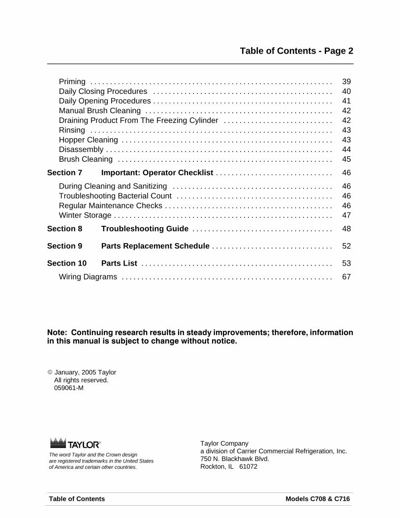
Table of Contents Models C708 & C716
Table of Contents - Page 2
Priming 39. . . . . . . . . . . . . . . . . . . . . . . . . . . . . . . . . . . . . . . . . . . . . . . . . . . . . . . . . . . . . .Daily Closing Procedures 40. . . . . . . . . . . . . . . . . . . . . . . . . . . . . . . . . . . . . . . . . . . . . .Daily Opening Procedures 41. . . . . . . . . . . . . . . . . . . . . . . . . . . . . . . . . . . . . . . . . . . . . .Manual Brush Cleaning 42. . . . . . . . . . . . . . . . . . . . . . . . . . . . . . . . . . . . . . . . . . . . . . . .Draining Product From The Freezing Cylinder 42. . . . . . . . . . . . . . . . . . . . . . . . . . . .Rinsing 43. . . . . . . . . . . . . . . . . . . . . . . . . . . . . . . . . . . . . . . . . . . . . . . . . . . . . . . . . . . . . .Hopper Cleaning 43. . . . . . . . . . . . . . . . . . . . . . . . . . . . . . . . . . . . . . . . . . . . . . . . . . . . . .Disassembly 44. . . . . . . . . . . . . . . . . . . . . . . . . . . . . . . . . . . . . . . . . . . . . . . . . . . . . . . . . .Brush Cleaning 45. . . . . . . . . . . . . . . . . . . . . . . . . . . . . . . . . . . . . . . . . . . . . . . . . . . . . . .
Section 7 Important: Operator Checklist 46. . . . . . . . . . . . . . . . . . . . . . . . . . . . . .
During Cleaning and Sanitizing 46. . . . . . . . . . . . . . . . . . . . . . . . . . . . . . . . . . . . . . . . .Troubleshooting Bacterial Count 46. . . . . . . . . . . . . . . . . . . . . . . . . . . . . . . . . . . . . . . .Regular Maintenance Checks 46. . . . . . . . . . . . . . . . . . . . . . . . . . . . . . . . . . . . . . . . . . .Winter Storage 47. . . . . . . . . . . . . . . . . . . . . . . . . . . . . . . . . . . . . . . . . . . . . . . . . . . . . . . .
Section 8 Troubleshooting Guide 48. . . . . . . . . . . . . . . . . . . . . . . . . . . . . . . . . . . .
Section 9 Parts Replacement Schedule 52. . . . . . . . . . . . . . . . . . . . . . . . . . . . . . .
Section 10 Parts List 53. . . . . . . . . . . . . . . . . . . . . . . . . . . . . . . . . . . . . . . . . . . . . . . . .
Wiring Diagrams 67. . . . . . . . . . . . . . . . . . . . . . . . . . . . . . . . . . . . . . . . . . . . . . . . . . . . . .
Note: Continuing research results in steady improvements; therefore, informationin this manual is subject to change without notice.
E January, 2005 TaylorAll rights reserved.059061-M
The word Taylor and the Crown designare registered trademarks in the United Statesof America and certain other countries.
Taylor Companya division of Carrier Commercial Refrigeration, Inc.750 N. Blackhawk Blvd.Rockton, IL 61072
1Models C708 & C716 To the Installer081208
Section 1 To the Installer
The following are general installation instructions.For complete installation details, please see thecheck out card.
Installer Safety
In all areas of the world, equipment shouldbe installed in accordance with existing local codes.Please contact your local authorities if you have anyquestions.
Care should be taken to ensure that all basic safetypractices are followed during the installation andservicing activities related to the installation andservice of Taylor equipment.
S Only authorized Taylor service personnelshould perform installation and repairs onthe equipment.
S Authorized service personnel should consultOSHA Standard 29CFRI910.147 or theapplicable code of the local area for theindustry standards on lockout/tagoutprocedures before beginning any installationor repairs.
S Authorized service personnel must ensurethat the proper PPE is available and wornwhen required during installation andservice.
S Authorized service personnel must removeall metal jewelry, rings, and watches beforeworking on electrical equipment.
The main power supply(s) to the freezermust be disconnected prior to performing anyrepairs. Failure to follow this instruction may result inpersonal injury or death from electrical shock orhazardous moving parts as well as poorperformance or damage to the equipment.
Note: All repairs must be performed by anauthorized Taylor Service Technician.
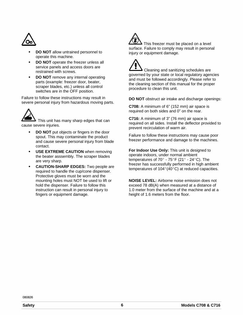
This unit has many sharp edges that cancause severe injuries.
Site Preparation
Review the area the unit is to be installed in beforeuncrating the unit making sure that all possiblehazards the user or equipment may come into havebeen addressed.
For Indoor Use Only: This unit is designed tooperate indoors, under normal ambienttemperatures of 70_-75_F (21_-24_C). The freezerhas successfully performed in high ambienttemperatures of 104_(40_C) at reduced capacities.
This unit must NOT be installed in an areawhere a water jet or hose can be used. NEVER usea water jet or hose to rinse or clean the unit. Failureto follow this instruction may result in electrocution.
This unit must be installed on a level surfaceto avoid the hazard of tipping. Extreme care shouldbe taken in moving this equipment for any reason.Two or more persons are required to safely movethis unit. Failure to comply may result in personalinjury or equipment damage.
Uncrate the unit and inspect it for damage. Reportany damage to your Taylor Distributor.
This piece of equipment is made in the USA and hasUSA sizes of hardware. All metric conversions areapproximate and vary in size.
2 Models C708 & C716To the Installer
080912
Air Cooled Units
DO NOT obstruct air intake and discharge openings:
Model C708: Requires a minimum of 6” (152 mm) ofclearance on both sides and 0” in the rear of theunit.Model C716: Requires a minimum of 3” (76 mm) ofclearance on all sides. Install the deflector providedto prevent recirculation of warm air.
This will allow for adequate air flow across thecondensers. Failure to allow adequate clearance canreduce the refrigeration capacity of the freezers andpossibly cause permanent damage to thecompressors.
Water Connections(Water Cooled Units Only)
An adequate cold water supply must be providedwith a hand shut-off valve. On the underside of thebase pan or on the right side, two 3/8” I.P.S. waterconnections for inlet and outlet are provided for easyhook-up. 1/2” inside diameter water lines should beconnected to the machine. (Flexible lines arerecommended, if local codes permit.) Depending onlocal water conditions, it may be advisable to installa water strainer to prevent foreign substances fromclogging the automatic water valve. There will beonly one water “in” and one water “out” connection.DO NOT install a hand shut-off valve on the water“out” line! Water should always flow in this order:first, through the automatic water valve; second,through the condenser; and third, through the outletfitting to an open trap drain.
A back flow prevention device isrequired on the incoming water connection side.Please refer to the applicable National, State, andlocal codes for determining the proper configuration.
Electrical Connections
In the United States, this equipment is intended tobe installed in accordance with the NationalElectrical Code (NEC), ANSI/NFPA 70-1987. Thepurpose of the NEC code is the practicalsafeguarding of persons and property from hazardsarising from the use of electricity. This code containsprovisions considered necessary for safety. In allother areas of the world, equipment should beinstalled in accordance with the existing local codes.Please contact your local authorities.
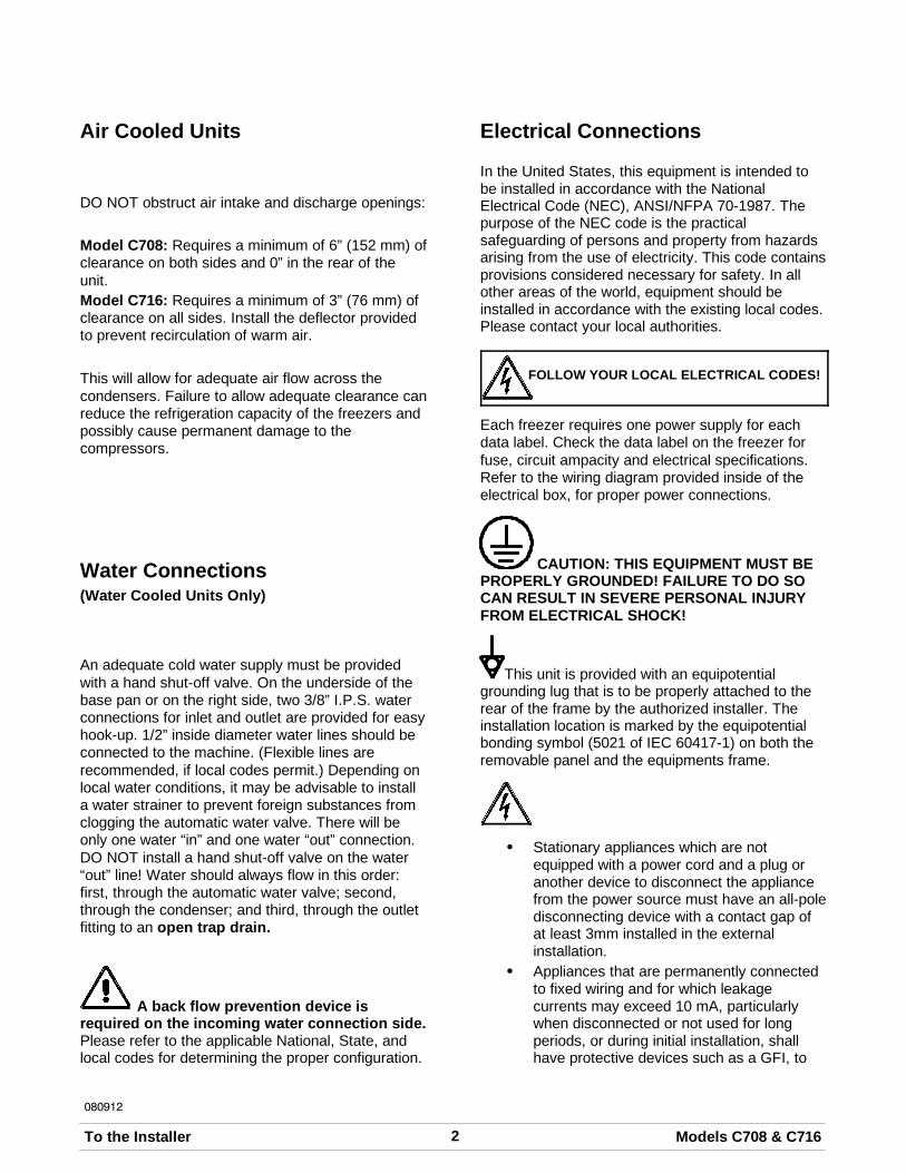
FOLLOW YOUR LOCAL ELECTRICAL CODES!
Each freezer requires one power supply for eachdata label. Check the data label on the freezer forfuse, circuit ampacity and electrical specifications.Refer to the wiring diagram provided inside of theelectrical box, for proper power connections.
CAUTION: THIS EQUIPMENT MUST BEPROPERLY GROUNDED! FAILURE TO DO SOCAN RESULT IN SEVERE PERSONAL INJURYFROM ELECTRICAL SHOCK!
This unit is provided with an equipotentialgrounding lug that is to be properly attached to therear of the frame by the authorized installer. Theinstallation location is marked by the equipotentialbonding symbol (5021 of IEC 60417-1) on both theremovable panel and the equipments frame.
S Stationary appliances which are notequipped with a power cord and a plug oranother device to disconnect the appliancefrom the power source must have an all-poledisconnecting device with a contact gap ofat least 3mm installed in the externalinstallation.
S Appliances that are permanently connectedto fixed wiring and for which leakagecurrents may exceed 10 mA, particularlywhen disconnected or not used for longperiods, or during initial installation, shallhave protective devices such as a GFI, to
3Models C708 & C716 To the Installer080912
protect against the leakage of current,installed by the authorized personnel to thelocal codes.
S Supply cords used with this unit shall beoil-resistant, sheathed flexible cable notlighter than ordinary polychloroprene orother equivalent syntheticelastomer-sheathed cord (Code designation60245 IEC 57) installed with the proper cordanchorage to relieve conductors from strain,including twisting, at the terminals andprotect the insulation of the conductors fromabrasion.
Beater Rotation
Beater rotation must be clockwise as viewedlooking into the freezing cylinder.
Note: The following procedures must be performedby an authorized Taylor service technician.
To correct rotation on a three-phase unit,interchange any two incoming power supply lines atfreezer main terminal block only.
To correct rotation on a single-phase unit, changethe leads inside the beater motor. (Follow diagramprinted on motor.)
Electrical connections are made directly to theterminal block provided in the main control box,located: C708 - behind the rear panel.
C716 - behind the lower front panel.
Refrigerant
In consideration of our environment, Taylorproudly uses only earth friendly HFC refrigerants.The HFC refrigerant used in this unit is R404A. Thisrefrigerant is generally considered non-toxic andnon-flammable, with an Ozone Depleting Potential(ODP) of zero (0).
However, any gas under pressure is potentiallyhazardous and must be handled with caution.
NEVER fill any refrigerant cylinder completely withliquid. Filling the cylinder to approximately 80% willallow for normal expansion.
Refrigerant liquid sprayed onto the skin maycause serious damage to tissue. Keep eyes and skinprotected. If refrigerant burns should occur, flushimmediately with cold water. If burns are severe,apply ice packs and contact a physicianimmediately.
Taylor reminds technicians to be cautious ofgovernment laws regarding refrigerant recovery,recycling, and reclaiming systems. If you have anyquestions regarding these laws, please contact thefactory Service Department.
WARNING: R404A refrigerant used inconjunction with polyolester oils is extremelymoisture absorbent. When opening a refrigerationsystem, the maximum time the system is open mustnot exceed 15 minutes. Cap all open tubing toprevent humid air or water from being absorbed bythe oil.
4 Models C708 & C716To the Operator
080714
Section 2 To the Operator
Your freezers have been carefully engineered andmanufactured to give you dependable operation.These units, when properly operated and cared for,will produce a consistent quality product. Like allmechanical products, they will require cleaning andmaintenance. A minimum amount of care andattention is necessary if the operating proceduresoutlined in this manual are followed closely.
This Operator's Manual should be read beforeoperating or performing any maintenance on yourequipment.
Your Taylor freezer will NOT eventually compensatefor and correct any errors during the set-up or fillingoperations. Thus, the initial assembly and primingprocedures are of extreme importance. It is stronglyrecommended that personnel responsible for theequipment's operation, both assembly anddisassembly, go through these procedures togetherin order to be properly trained and to make sure thatno confusion exists.
In the event you should require technical assistance,please contact your local authorized TaylorDistributor.
Note: Warranty is valid only if the parts areauthorized Taylor parts, purchased from anauthorized Taylor Distributor, and the requiredservice work is provided by an authorized Taylorservice technician. Taylor reserves the right to denywarranty claims on equipment or parts ifnon-approved parts or refrigerant were installed inthe machine, system modifications were performedbeyond factory recommendations, or it is determinedthat the failure was caused by neglect or abuse.
Note: Constant research results in steadyimprovements; therefore, information in thismanual is subject to change without notice.
If the crossed out wheeled bin symbol isaffixed to this product, it signifies that this product iscompliant with the EU Directive as well as othersimilar legislation in effect after August 13, 2005.Therefore, it must be collected separately after itsuse is completed, and cannot be disposed asunsorted municipal waste.
The user is responsible for returning the product tothe appropriate collection facility, as specified byyour local code.
For additional information regarding applicable locallaws, please contact the municipal facility and/orlocal distributor.
Compressor Warranty Disclaimer
The refrigeration compressors on this machine arewarranted for the term indicated on the warrantycard accompanying this machine. However, due tothe Montreal Protocol and the U.S. Clean Air ActAmendments of 1990, many new refrigerants arebeing tested and developed, thus seeking their wayinto the service industry. Some of these newrefrigerants are being advertised as drop-inreplacements for numerous applications. It shouldbe noted that, in the event of ordinary service to thismachine's refrigeration system, only the refrigerantspecified on the affixed data label should beused. The unauthorized use of alternate refrigerantswill void your compressor warranty. It will be theowner's responsibility to make this fact known to anytechnician he employs.
It should also be noted that Taylor does not warrantthe refrigerant used in its equipment. For example, ifthe refrigerant is lost during the course of ordinaryservice to this machine, Taylor has no obligation toeither supply or provide its replacement either atbillable or unbillable terms. Taylor does have theobligation to recommend a suitable replacement ifthe original refrigerant is banned, obsoleted, or nolonger available during the five year warranty of thecompressor.
Taylor will continue to monitor the industry and testnew alternates as they are being developed. Shoulda new alternate prove, through our testing, that itwould be accepted as a drop-in replacement, thenthe above disclaimer would become null and void.To find out the current status of an alternaterefrigerant as it relates to your compressor warranty,call the local Taylor Distributor or the Taylor Factory.Be prepared to provide the Model/Serial Number ofthe unit in question.
5Models C708 & C716 Safety080912
Section 3 Safety
We at Taylor Company are concerned about thesafety of the operator when he or she comes incontact with the freezer and its parts. Taylor hasgone to extreme efforts to design and manufacturebuilt-in safety features to protect both you and theservice technician. As an example, warning labelshave been attached to the freezer to further pointout safety precautions to the operator.
IMPORTANT - Failure to adhere to thefollowing safety precautions may result insevere personal injury or death. Failure tocomply with these warnings may damage themachine and its components. Componentdamage will result in part replacement expenseand service repair expense.
DO NOT operate the freezer withoutreading this Operator Manual. Failure to follow thisinstruction may result in equipment damage, poorfreezer performance, health hazards, or personalinjury.
This unit is provided with an equipotentialgrounding lug that is to be properly attached to therear of the frame by the authorized installer. Theinstallation location is marked by the equipotentialbonding symbol (5021 of IEC 60417-1) on both theremovable panel and the equipments frame.
DO NOT use a water jet to clean or rinsethe freezer. Failure to follow these instructions mayresult in serious electrical shock.
S DO NOT operate the freezer unless it isproperly grounded.
S DO NOT operate the freezer with largerfuses than specified on the freezer datalabel.
S DO NOT attempt any repairs unless themain power supply to the freezer has beendisconnected. Contact your local authorizedTaylor Distributor for service.
S Stationary appliances which are notequipped with a power cord and a plug oranother device to disconnect the appliancefrom the power source must have an all-poledisconnecting device with a contact gap ofat least 3mm installed in the externalinstallation.
S Appliances that are permanently connectedto fixed wiring and for which leakagecurrents may exceed 10 mA, particularlywhen disconnected or not used for longperiods, or during initial installation, shallhave protective devices such as a GFI, toprotect against the leakage of current,installed by the authorized personnel to thelocal codes.
S Supply cords used with this unit shall beoil-resistant, sheathed flexible cable notlighter than ordinary polychloroprene orother equivalent syntheticelastomer-sheathed cord (Code designation60245 IEC 57) installed with the proper cordanchorage to relieve conductors from strain,including twisting, at the terminals andprotect the insulation of the conductors fromabrasion.
Failure to follow these instructions may result inelectrocution. Contact your local authorized TaylorDistributor for service.
6 Models C708 & C716Safety
080826
S DO NOT allow untrained personnel tooperate this machine.
S DO NOT operate the freezer unless allservice panels and access doors arerestrained with screws.
S DO NOT remove any internal operatingparts (example: freezer door, beater,scraper blades, etc.) unless all controlswitches are in the OFF position.
Failure to follow these instructions may result insevere personal injury from hazardous moving parts.
This unit has many sharp edges that cancause severe injuries.
S DO NOT put objects or fingers in the doorspout. This may contaminate the productand cause severe personal injury from bladecontact.
S USE EXTREME CAUTION when removingthe beater asssembly. The scraper bladesare very sharp.
S CAUTION-SHARP EDGES: Two people arerequired to handle the cup/cone dispenser.Protective gloves must be worn and themounting holes must NOT be used to lift orhold the dispenser. Failure to follow thisinstruction can result in personal injury tofingers or equipment damage.
This freezer must be placed on a levelsurface. Failure to comply may result in personalinjury or equipment damage.
Cleaning and sanitizing schedules aregoverned by your state or local regulatory agenciesand must be followed accordingly. Please refer tothe cleaning section of this manual for the properprocedure to clean this unit.
DO NOT obstruct air intake and discharge openings:
C708: A minimum of 6” (152 mm) air space isrequired on both sides and 0” on the rear.
C716: A minimum of 3” (76 mm) air space isrequired on all sides. Install the deflector provided toprevent recirculation of warm air.
Failure to follow these instructions may cause poorfreezer performance and damage to the machines.
For Indoor Use Only: This unit is designed tooperate indoors, under normal ambienttemperatures of 70_ - 75_F (21_ - 24_C). Thefreezer has successfully performed in high ambienttemperatures of 104_(40_C) at reduced capacities.
NOISE LEVEL: Airborne noise emission does notexceed 78 dB(A) when measured at a distance of1.0 meter from the surface of the machine and at aheight of 1.6 meters from the floor.
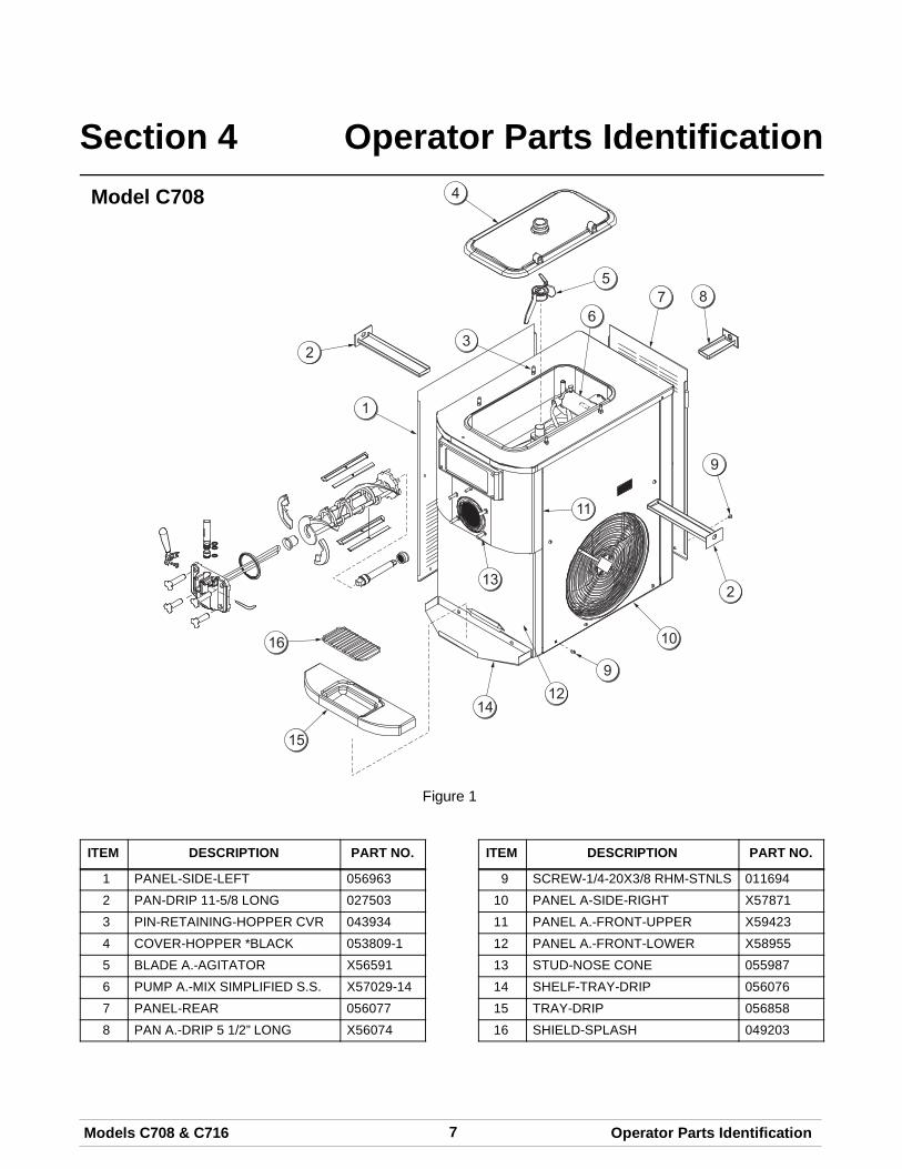
7Models C708 & C716 Operator Parts Identification
Section 4 Operator Parts IdentificationModel C708
Figure 1
ITEM DESCRIPTION PART NO.
1 PANEL-SIDE-LEFT 0569632 PAN-DRIP 11-5/8 LONG 0275033 PIN-RETAINING-HOPPER CVR 0439344 COVER-HOPPER *BLACK 053809-15 BLADE A.-AGITATOR X565916 PUMP A.-MIX SIMPLIFIED S.S. X57029-147 PANEL-REAR 0560778 PAN A.-DRIP 5 1/2” LONG X56074
ITEM DESCRIPTION PART NO.
9 SCREW-1/4-20X3/8 RHM-STNLS 01169410 PANEL A-SIDE-RIGHT X5787111 PANEL A.-FRONT-UPPER X5942312 PANEL A.-FRONT-LOWER X5895513 STUD-NOSE CONE 05598714 SHELF-TRAY-DRIP 05607615 TRAY-DRIP 05685816 SHIELD-SPLASH 049203
8 Models C708 & C716Operator Parts Identification
061228
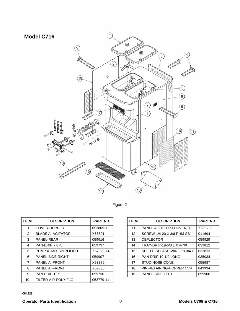
Model C716
Figure 2
ITEM DESCRIPTION PART NO.
1 COVER-HOPPER 053809-12 BLADE A.-AGITATOR X565913 PANEL-REAR 0599164 PAN-DRIP 7.875 0597375 PUMP A.-MIX SIMPLIFIED X57029-146 PANEL-SIDE-RIGHT 0599077 PANEL A.-FRONT X638798 PANEL A.-FRONT X598369 PAN-DRIP 12.5 05973610 FILTER-AIR-POLY-FLO 052779-11
ITEM DESCRIPTION PART NO.
11 PANEL A.-FILTER-LOUVERED X5992812 SCREW-1/4-20 X 3/8 RHM-SS 01169413 DEFLECTOR 05992914 TRAY-DRIP-19-5/8 L X 4-7/8 03381215 SHIELD-SPLASH-WIRE-19-3/4 L 03381316 PAN-DRIP 19-1/2 LONG 03503417 STUD-NOSE CONE 05598718 PIN-RETAINING-HOPPER CVR 04393419 PANEL-SIDE-LEFT 059906
9Models C708 & C716 Operator Parts Identification
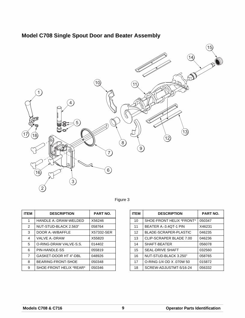
Model C708 Single Spout Door and Beater Assembly
Figure 3
ITEM DESCRIPTION PART NO.
1 HANDLE A.-DRAW-WELDED X562462 NUT-STUD-BLACK 2.563“ 0587643 DOOR A.-W/BAFFLE X57332-SER4 VALVE A.-DRAW X558205 O-RING-DRAW VALVE-S.S. 0144026 PIN-HANDLE-SS 0558197 GASKET-DOOR HT 4”-DBL 0489268 BEARING-FRONT-SHOE 0503489 SHOE-FRONT HELIX *REAR* 050346
ITEM DESCRIPTION PART NO.
10 SHOE-FRONT HELIX *FRONT* 05034711 BEATER A.-3.4QT-1 PIN X4623112 BLADE-SCRAPER-PLASTIC 04623513 CLIP-SCRAPER BLADE 7.00 04623614 SHAFT-BEATER 05607815 SEAL-DRIVE SHAFT 03256016 NUT-STUD-BLACK 3.250” 05876517 O-RING-1/4 OD X .070W 50 01587218 SCREW-ADJUSTMT-5/16-24 056332
10 Models C708 & C716Operator Parts Identification
080805
Model C716 Door and Beater Assembly
Figure 4
ITEM DESCRIPTION PART NO.
1 HANDLE A.-DRAW-WELDED X56421-12 NUT-STUD-BLACK 3.250 LONG 0587653 NUT-STUD*BLACK 2.563 LONG 0587644 DOOR A.-3SPT*HT*LG BAF X59923-SER5 PIN-HANDLE-TWIN 0598946 GASKET-DOOR HT 4”-DOUBLE 048926-17 O-RING--7/8 OD X .103W 0144028 VALVE A.-DRAW X598889 VALVE A.-DRAW*CENTER X5989010 SHOE-FRONT HELIX *FRONT* 050347
ITEM DESCRIPTION PART NO.
11 BEARING-FRONT-SHOE 05034812 SHOE-FRONT HELIX *REAR* 05034613 BLADE-SCRAPER-PLAS 8-1/8L 04623514 CLIP-SCRAPER BLADE 7.00” 04623615 BEATER A.-3.4QT-1 PIN X4623116 SHAFT-BEATER 03256417 SEAL-DRIVE SHAFT 03256018 O-RING-1/4 OD X .070W 50 01587219 SCREW-ADJUSTMENT-5/16-24 05633220 SEAL-DRAW VALVE H-RING 034698
11Models C708 & C716 Operator Parts Identification
X57029-XX Pump A. - Mix Simplified (Model C708)
Figure 5
ITEM DESCRIPTION PART NO.
1 - 7 PUMP ASSEMBLY - MIXSIMPLIFIED SOFT SERVE
X57029-14*
1 CYLINDER-PUMP-HOPPER-SOFT SERVE
057943
2 PIN A.-RETAINING X554503 PISTON 0535264 O-RING 2-1/8” OD - RED 0200515 CAP-VALVE 056874-14*6 GASKET - SIMPLIFIED PUMP
VALVE053527
7 ADAPTOR - MIX INLET 0548258 O-RING - 11/16 OD - RED 016132
ITEM DESCRIPTION PART NO.
9 PIN - COTTER 04473110 SHAFT A.-DRIVE-MIX PUMP-
HOPPERX41947
10a CRANK-DRIVE 03923510b SHAFT-DRIVE 04194811 O-RING - DRIVE SHAFT 04863212 O-RING 1-3/4 00890413 CLIP-MIX PUMP RETAINER 04464114 TUBE A.-FEED HOPPER
SOFT SERVEX56521
15 RING-CHECK .120 OD 056524*NOTE: THE STANDARD PUMP X57029-XX IS A -14.OVERRUN CAN BE CHANGED HIGHER OR LOWERBY SUBSTITUTING THE CAP (056874-XX) WITHCAPS AVAILABLE -1 THROUGH -20. THE HIGHERTHE DASH (-) NUMBER, THE HIGHER THEOVERRUN.
12 Models C708 & C716Operator Parts Identification
X57029-XX Pump A. - Mix Simplified (Model C716)
Figure 6
ITEM DESCRIPTION PART NO.
1 - 7 PUMP ASSEMBLY - MIXSIMPLIFIED SOFT SERVE
X57029-14*
1 CYLINDER-PUMP-HOPPER-SOFT SERVE
057943
2 PIN A.-RETAINING X554503 PISTON 0535264 O-RING 2-1/8” OD - RED 0200515 CAP-VALVE 056874-14*6 GASKET - SIMPLIFIED PUMP
VALVE053527
7 ADAPTOR - MIX INLET 0548258 O-RING - 11/16 OD - RED 016132
ITEM DESCRIPTION PART NO.
9 PIN - COTTER 04473110 SHAFT A.-DRIVE-MIX PUMP-
HOPPERX41947
10a CRANK-DRIVE 03923510b SHAFT-DRIVE 04194811 O-RING - DRIVE SHAFT 04863212 O-RING 1-3/4 00890413 CLIP-MIX PUMP RETAINER 04464114 RING-CHECK .120 OD 05652415 TUBE A.-FEED-LEFT X5980816 TUBE A.-FEED-RIGHT X59809
*NOTE: THE STANDARD PUMP X57029-XX IS -14.OVERRUN CAN BE CHANGED HIGHER OR LOWERBY SUBSTITUTING THE CAP (056874-XX) WITHCAPS AVAILABLE -1 THROUGH -20. THE HIGHERTHE DASH (-) NUMBER, THE HIGHER THEOVERRUN.
13Models C708 & C716 Operator Parts Identification060629
Accessories
Figure 7
ITEM DESCRIPTION PART NO.
1 SANITIZER-KAY 5 CASE 125 0410822 TOOL-O-RING REMOVAL 048260-WHT3 TOOL-SHAFT-DRIVE-PUMP-
HOPPER057167
4 LUBRICANT-TAYLOR HI-PERF 048232
ITEM DESCRIPTION PART NO.
5 PAIL-MIX 10 QT. 013163* KIT A.-TUNE-UP (C708) X56085* KIT A.-TUNE-UP (C716) X49463-82* KIT A.-PARTS TRAY (C708) X57797* KIT A.-PARTS TRAY (C716) X58449
*NOT SHOWN
14 Models C708 & C716Operator Parts Identification
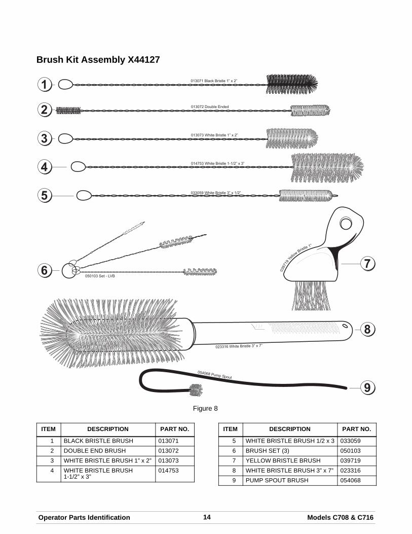
Brush Kit Assembly X44127
Figure 8
ITEM DESCRIPTION PART NO.
1 BLACK BRISTLE BRUSH 0130712 DOUBLE END BRUSH 0130723 WHITE BRISTLE BRUSH 1” x 2” 0130734 WHITE BRISTLE BRUSH
1-1/2” x 3”014753
ITEM DESCRIPTION PART NO.
5 WHITE BRISTLE BRUSH 1/2 x 3 0330596 BRUSH SET (3) 0501037 YELLOW BRISTLE BRUSH 0397198 WHITE BRISTLE BRUSH 3” x 7” 0233169 PUMP SPOUT BRUSH 054068
15Models C708 & C716 Important: To the Operator
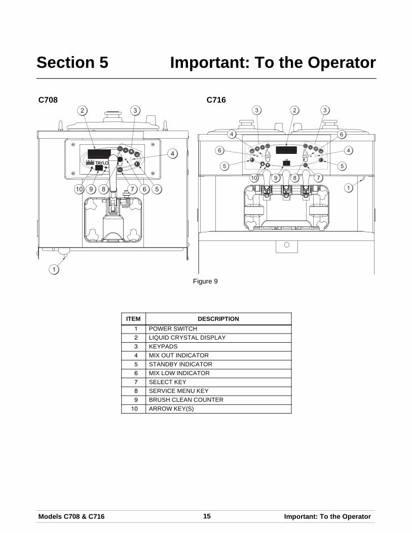
Section 5 Important: To the Operator
C708 C716
Figure 9
ITEM DESCRIPTION1 POWER SWITCH2 LIQUID CRYSTAL DISPLAY3 KEYPADS4 MIX OUT INDICATOR5 STANDBY INDICATOR6 MIX LOW INDICATOR7 SELECT KEY8 SERVICE MENU KEY9 BRUSH CLEAN COUNTER10 ARROW KEY(S)
16 Models C708 & C716Important: To the Operator
050628
Symbol Definitions
To better communicate in the International arena,symbols have replaced words on many of ouroperator switches, function, and fault indicators.Your Taylor equipment is designed with theseInternational symbols.
The following chart identifies the symbol definitions.
= SELECT
= UP ARROW
= DOWN ARROW
= AUTO
= HEAT CYCLE
= WASH
= MIX LOW
= MIX OUT
= MENU DISPLAY
= MIX PUMP
= STANDBY
Power SwitchWhen placed in the ON position, the power switchallows control panel operation.
Fluorescent DisplayThe fluorescent display is located on the frontcontrol panel. During normal operation the display isblank. The display is used to show menu optionsand notifies the operator if a fault is detected. OnInternational models, the display will indicate thetemperature of the mix in the hopper.
Indicator Lights
MIX LOW - When the MIX LOW symbol isilluminated, the mix hopper has a low supply of mixand should be refilled as soon as possible.
MIX OUT - When the MIX OUT symbol isilluminated, the mix hopper has been almostcompletely exhausted and has an insufficient supplyof mix to operate the freezer. At this time, the AUTOmode is locked out and the freezer will be placed inthe STANDBY mode. To initiate the refrigerationsystem, add mix to the mix hopper and touch theAUTO symbol . The freezer will automaticallybegin operation.
HEAT MODE - When the HEAT MODE symbol is illuminated, the freezer is in the process of a heatcycle.BRUSH CLEAN COUNTER - When the BRUSHCLEAN COUNTER display has counted down to “1”,the machine must be disassembled and brushcleaned within 24 hours.
Reset MechanismThe reset button is located in the service panel onthe left side of the C708. The reset buttons arelocated in the back panel of the C716. A reset buttonprotects the beater motor from an overloadcondition. Should an overload occur, the resetmechanism will trip. To properly reset the freezerplace the power switch in the OFF position. Pressthe reset button firmly. Turn the power switch to theON position. Touch the WASH symbol andobserve the freezer's performance.
WARNING:Donot usemetal objects topress the reset button. Failure to comply mayresult in severe personal injury or death.
17Models C708 & C716 Important: To the Operator050628
If the beater motor is turning properly, touch theWASH symbol to cancel the cycle. Touch theAUTO symbol to resume normal operation. If thefreezer shuts down again, contact your authorizedservice technician.
Air/Mix Pump Reset Mechanism
This reset button protects the pump from anoverload condition. Should an overload occur, thereset mechanism will trip. To reset the pump, pressthe reset button firmly.
WARNING: Do not use metal objects topress the reset button. Failure to comply mayresult in severe personal injury or death.
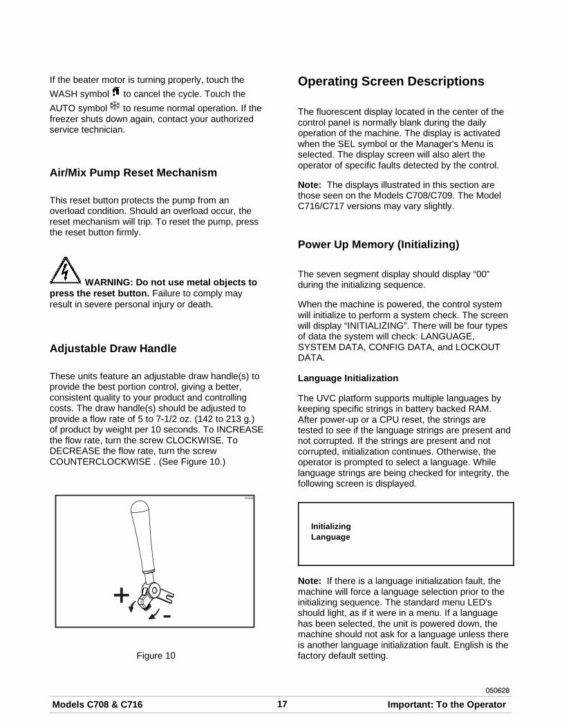
Adjustable Draw Handle
These units feature an adjustable draw handle(s) toprovide the best portion control, giving a better,consistent quality to your product and controllingcosts. The draw handle(s) should be adjusted toprovide a flow rate of 5 to 7-1/2 oz. (142 to 213 g.)of product by weight per 10 seconds. To INCREASEthe flow rate, turn the screw CLOCKWISE. ToDECREASE the flow rate, turn the screwCOUNTERCLOCKWISE . (See Figure 10.)
+-
10354
Figure 10
Operating Screen Descriptions
The fluorescent display located in the center of thecontrol panel is normally blank during the dailyoperation of the machine. The display is activatedwhen the SEL symbol or the Manager's Menu isselected. The display screen will also alert theoperator of specific faults detected by the control.
Note: The displays illustrated in this section arethose seen on the Models C708/C709. The ModelC716/C717 versions may vary slightly.
Power Up Memory (Initializing)
The seven segment display should display “00”during the initializing sequence.
When the machine is powered, the control systemwill initialize to perform a system check. The screenwill display “INITIALIZING”. There will be four typesof data the system will check: LANGUAGE,SYSTEM DATA, CONFIG DATA, and LOCKOUTDATA.
Language Initialization
The UVC platform supports multiple languages bykeeping specific strings in battery backed RAM.After power-up or a CPU reset, the strings aretested to see if the language strings are present andnot corrupted. If the strings are present and notcorrupted, initialization continues. Otherwise, theoperator is prompted to select a language. Whilelanguage strings are being checked for integrity, thefollowing screen is displayed.
InitializingLanguage
Note: If there is a language initialization fault, themachine will force a language selection prior to theinitializing sequence. The standard menu LED'sshould light, as if it were in a menu. If a languagehas been selected, the unit is powered down, themachine should not ask for a language unless thereis another language initialization fault. English is thefactory default setting.
18 Models C708 & C716Important: To the Operator
050628
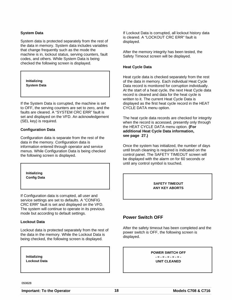
System Data
System data is protected separately from the rest ofthe data in memory. System data includes variablesthat change frequently such as the mode themachine is in, lockout status, serving counters, faultcodes, and others. While System Data is beingchecked the following screen is displayed.
InitializingSystem Data
If the System Data is corrupted, the machine is setto OFF, the serving counters are set to zero, and thefaults are cleared. A “SYSTEM CRC ERR” fault isset and displayed on the VFD. An acknowledgement(SEL key) is required.
Configuration Data
Configuration data is separate from the rest of thedata in the memory. Configuration data isinformation entered through operator and servicemenus. While Configuration Data is being checkedthe following screen is displayed.
InitializingConfig Data
If Configuration data is corrupted, all user andservice settings are set to defaults. A “CONFIGCRC ERR” fault is set and displayed on the VFD.The system will continue to operate in its previousmode but according to default settings.
Lockout Data
Lockout data is protected separately from the rest ofthe data in the memory. While the Lockout Data isbeing checked, the following screen is displayed.
InitializingLockout Data
If Lockout Data is corrupted, all lockout history datais cleared. A “LOCKOUT CRC ERR” fault isdisplayed.
After the memory integrity has been tested, theSafety Timeout screen will be displayed.
Heat Cycle Data
Heat cycle data is checked separately from the restof the data in memory. Each individual Heat CycleData record is monitored for corruption individually.At the start of a heat cycle, the next Heat Cycle datarecord is cleared and data for the heat cycle iswritten to it. The current Heat Cycle Data isdisplayed as the first heat cycle record in the HEATCYCLE DATA menu option.
The heat cycle data records are checked for integritywhen the record is accessed, presently only throughthe HEAT CYCLE DATA menu option. (Foradditional Heat Cycle Data information,see page 27.)
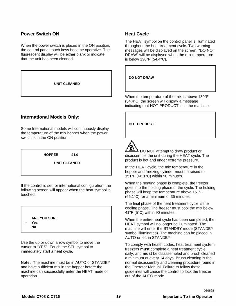
Once the system has initialized, the number of daysuntil brush cleaning is required is indicated on thecontrol panel. The SAFETY TIMEOUT screen willbe displayed with the alarm on for 60 seconds oruntil any control symbol is touched.
SAFETY TIMEOUTANY KEY ABORTS
Power Switch OFF
After the safety timeout has been completed and thepower switch is OFF, the following screen isdisplayed.
POWER SWITCH OFF- = - = - = - = - = -UNIT CLEANED
19Models C708 & C716 Important: To the Operator050628
Power Switch ON
When the power switch is placed in the ON position,the control panel touch keys become operative. Thefluorescent display will be either blank or indicatethat the unit has been cleaned.
UNIT CLEANED
International Models Only:
Some International models will continuously displaythe temperature of the mix hopper when the powerswitch is in the ON position.
HOPPER 21.0
UNIT CLEANED
If the control is set for international configuration, thefollowing screen will appear when the heat symbol istouched.
ARE YOU SURE> Yes
No
Use the up or down arrow symbol to move thecursor to “YES”. Touch the SEL symbol toimmediately start a heat cycle.
Note: The machine must be in AUTO or STANDBYand have sufficient mix in the hopper before themachine can successfully enter the HEAT mode ofoperation.
Heat CycleThe HEAT symbol on the control panel is illuminatedthroughout the heat treatment cycle. Two warningmessages will be displayed on the screen. “DO NOTDRAW” will be displayed when the mix temperatureis below 130°F (54.4°C).
DO NOT DRAW
When the temperature of the mix is above 130°F(54.4°C) the screen will display a messageindicating that HOT PRODUCT is in the machine.
HOT PRODUCT
DO NOT attempt to draw product ordisassemble the unit during the HEAT cycle. Theproduct is hot and under extreme pressure.
In the HEAT cycle, the mix temperature in thehopper and freezing cylinder must be raised to151°F (66.1°C) within 90 minutes.
When the heating phase is complete, the freezergoes into the holding phase of the cycle. The holdingphase will keep the temperature above 151°F(66.1°C) for a minimum of 35 minutes.
The final phase of the heat treatment cycle is thecooling phase. The freezer must cool the mix below41°F (5°C) within 90 minutes.
When the entire heat cycle has been completed, theHEAT symbol will no longer be illuminated. Themachine will enter the STANDBY mode (STANDBYsymbol illuminates). The machine can be placed inAUTO or left in STANDBY.
To comply with health codes, heat treatment systemfreezers must complete a heat treatment cycledaily, and must be disassembled and brush cleaneda minimum of every 14 days. Brush cleaning is thenormal disassembly and cleaning procedure found inthe Operator Manual. Failure to follow theseguidelines will cause the control to lock the freezerout of the AUTO mode.
20 Models C708 & C716Important: To the Operator
080222
If the Heat Treatment Cycle fails, the screen willdisplay a failure message and return the freezer tothe STANDBY mode.
Always comply with local guidelines for themaximum number of days allowed between brushclean cycles.
Freezer Locks
There are two types of freezer lock conditions thatcan occur: Hard Lock or Soft Lock. A Hard Lockrequires the machine be disassembled and brushcleaned. A Soft Lock can be corrected by eitherdisassembling and brush cleaning the machine, orby starting another heat treatment cycle.
HardlockThere are two causes of a hard lock failure. Thefreezer will hardlock if either the Brush Clean Timerhas elapsed or if a Thermistor Failure (FreezingCylinder or Hopper) occurred during a Heat cycle.
1. The following screen will be displayed if a BrushClean Cycle Time has occurred.
BRUSH CLEAN TIMEOUTFREEZER LOCKEDCLEANING REQ'D
> BRUSH CLEAN
Touching the SEL symbol will display the followingscreen.
FREEZER LOCKED
2. The following screen will display if there hasbeen a thermistor failure (freezing cylinder orhopper) during the heat treatment process.
SYSTEM FAULTFREEZER LOCKEDSERVICE REQ'D
> BRUSH CLEAN
Touching the SEL symbol will indicate whichthermistor caused the Hard Lock.
HOPPER THERM BAD
FREEZER LOCKED
If the machine has hard locked and an attempt ismade to enter AUTO, the machine will enter theSTANDBY mode and display the following message.
FREEZER LOCKED
To restore the message that identified the reason forthe hard lock, turn the power switch OFF for fiveseconds and then return the power switch to the ONposition. The original message with the reason forthe Hard Lock will be displayed.
The FREEZER LOCKED message will remain onthe display until the brush clean requirements arefulfilled. The freezer must be disassembled in orderto activate the five minute timer on the displayscreen. Once the timer counts down to zero, thelockout is cleared.
Soft LockIf a heat treatment cycle has not been initiated withinthe last 24 hours, a soft lock failure will occur. A softlock allows the operator to correct the cause of thesoft lock. The operator has the option of eitherstarting another heat cycle or brush cleaning themachine. When a soft lock occurs, the machine willgo into the STANDBY mode. The following messageis displayed on the screen. The reason for the softlock is indicated on the second line.
NO HEAT CYCLE STARTREASON
> HEAT CYCLEBRUSH CLEAN
If the reason for the soft lock has been corrected,selecting HEAT CYCLE initiates a Heat Cycleimmediately. Selecting BRUSH CLEAN when theprevious message is displayed will hard lock themachine and brush cleaning will be necessary.
21Models C708 & C716 Important: To the Operator050628
Following are the variable messages for soft lockfailures that appear on the second line of the screen.
POWER SWITCH OFF Power switch was in theOFF position.
MIX OUT PRESENT There was a mix outcondition present.
AUTO OR STANDBYOFF
The machine was not inthe AUTO or STANDBYmode.
NO HEAT CYCLETRIED
A heat treatment cyclewas not attempted inthe last 24 hours.(AUTO HEAT TIMEwas advanced or a pow-er loss was experiencedat the time the cyclewas to occur.)
If the following screen appears, a soft lock hasoccurred during the heat treatment cycle.
HEAT TREAT FAILUREFREEZER LOCKED
> HEAT CYCLEBRUSH CLEAN
A soft lock can also occur any time during operationwhen the hopper or freezing cylinder temperaturerises above 59°F (15°C), the temperature rises andremains above 45°F(7°C) for more than one hour, orthe temperature rises and remains above 41°F(5°C)for more than four hours.
If a PRODUCT OVER TEMPERATURE conditionoccurs during operation, the following screen willappear.
PRODUCT OVER TEMP
> HEAT CYCLEBRUSH CLEAN
When one of these messages appears, automaticfreezer operation cannot take place until the freezeris disassembled and brush cleaned, or hascompleted a heat treatment cycle.
Once the freezer is unlocked by starting a heattreatment cycle the HEAT symbol will illuminate andthe following message will be displayed on thescreen.
DO NOT DRAW
If BRUSH CLEAN is selected to clear the lockout bybrush cleaning the machine, the FREEZERLOCKED message will remain on the display untilthe brush clean requirements are fulfilled. Thefreezer must be disassembled in order to activatethe five minute timer on the display screen. Oncethe timer counts down to zero, the lockout iscleared.
FREEZER LOCKED
To restore the message that identified the reason forthe soft lock, turn the power switch OFF for fiveseconds, and then return the power switch to theON position. The original message with the reasonfor the soft lock will be displayed.
HEAT TREAT FAILUREREASON
> HEAT CYCLEBRUSH CLEAN
Note: A record of Heat Cycle Data and Lock OutHistory can be found in the Manager's Menu.
22 Models C708 & C716Important: To the Operator
060413
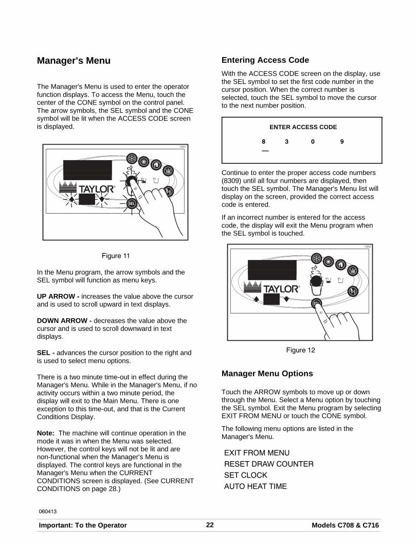
Manager's Menu
The Manager's Menu is used to enter the operatorfunction displays. To access the Menu, touch thecenter of the CONE symbol on the control panel.The arrow symbols, the SEL symbol and the CONEsymbol will be lit when the ACCESS CODE screenis displayed.
Figure 11
In the Menu program, the arrow symbols and theSEL symbol will function as menu keys.
UP ARROW - increases the value above the cursorand is used to scroll upward in text displays.
DOWN ARROW - decreases the value above thecursor and is used to scroll downward in textdisplays.
SEL - advances the cursor position to the right andis used to select menu options.
There is a two minute time-out in effect during theManager's Menu. While in the Manager's Menu, if noactivity occurs within a two minute period, thedisplay will exit to the Main Menu. There is oneexception to this time-out, and that is the CurrentConditions Display.
Note: The machine will continue operation in themode it was in when the Menu was selected.However, the control keys will not be lit and arenon-functional when the Manager's Menu isdisplayed. The control keys are functional in theManager's Menu when the CURRENTCONDITIONS screen is displayed. (See CURRENTCONDITIONS on page 28.)
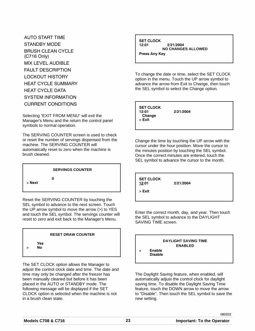
Entering Access CodeWith the ACCESS CODE screen on the display, usethe SEL symbol to set the first code number in thecursor position. When the correct number isselected, touch the SEL symbol to move the cursorto the next number position.
ENTER ACCESS CODE
8 3 0 9__
Continue to enter the proper access code numbers(8309) until all four numbers are displayed, thentouch the SEL symbol. The Manager's Menu list willdisplay on the screen, provided the correct accesscode is entered.
If an incorrect number is entered for the accesscode, the display will exit the Menu program whenthe SEL symbol is touched.
Figure 12
Manager Menu Options
Touch the ARROW symbols to move up or downthrough the Menu. Select a Menu option by touchingthe SEL symbol. Exit the Menu program by selectingEXIT FROM MENU or touch the CONE symbol.
The following menu options are listed in theManager's Menu.
EXIT FROM MENU
RESET DRAW COUNTER
SET CLOCK
AUTO HEAT TIME
23Models C708 & C716 Important: To the Operator080222
AUTO START TIME
STANDBY MODE
BRUSH CLEAN CYCLE(C716 Only)
MIX LEVEL AUDIBLE
FAULT DESCRIPTION
LOCKOUT HISTORY
HEAT CYCLE SUMMARY
HEAT CYCLE DATA
SYSTEM INFORMATION
CURRENT CONDITIONS
Selecting “EXIT FROM MENU” will exit theManager's Menu and the return the control panelsymbols to normal operation.
The SERVING COUNTER screen is used to checkor reset the number of servings dispensed from themachine. The SERVING COUNTER willautomatically reset to zero when the machine isbrush cleaned.
SERVINGS COUNTER
0> Next
Reset the SERVING COUNTER by touching theSEL symbol to advance to the next screen. Touchthe UP arrow symbol to move the arrow (>) to YESand touch the SEL symbol. The servings counter willreset to zero and exit back to the Manager's Menu.
RESET DRAW COUNTER
Yes> No
The SET CLOCK option allows the Manager toadjust the control clock date and time. The date andtime may only be changed after the freezer hasbeen manually cleaned but before it has beenplaced in the AUTO or STANDBY mode. Thefollowing message will be displayed if the SETCLOCK option is selected when the machine is notin a brush clean state.
SET CLOCK12:01 2/21/2004
NO CHANGES ALLOWEDPress Any Key
To change the date or time, select the SET CLOCKoption in the menu. Touch the UP arrow symbol toadvance the arrow from Exit to Change, then touchthe SEL symbol to select the Change option.
SET CLOCK12:01 2/21/2004Change
> Exit
Change the time by touching the UP arrow with thecursor under the hour position. Move the cursor tothe minutes position by touching the SEL symbol.Once the correct minutes are entered, touch theSEL symbol to advance the cursor to the month.
SET CLOCK12:01 2/21/2004
> Exit
Enter the correct month, day, and year. Then touchthe SEL symbol to advance to the DAYLIGHTSAVING TIME screen.
DAYLIGHT SAVING TIMEENABLED
> EnableDisable
The Daylight Saving feature, when enabled, willautomatically adjust the control clock for daylightsaving time. To disable the Daylight Saving Timefeature, touch the DOWN arrow to move the arrowto “Disable”. Then touch the SEL symbol to save thenew setting.
24 Models C708 & C716Important: To the Operator
080222
The AUTO HEAT TIME screen allows the Managerto set the time of day in which the heat treatmentcycle will start.
AUTO HEAT TIME00:00
Change> Exit
To set the AUTO HEAT TIME, touch the UP arrowsymbol to move the arrow to “Change”. Then touchthe SEL symbol. The screen will display the timewith the cursor under the hour position.
AUTO HEAT TIME00:00
Touch the arrow symbols to increase or decreasethe hour to the desired setting. Then move thecursor to the minutes position by touching the SELsymbol. Adjust the setting for minutes. Then touchthe SEL symbol to save the setting and return to theAUTO HEAT TIME screen. Touch the SEL symbolto exit the screen and return to the Menu.
The AUTO START TIME option allows the Managerto set the time of day at which the machineautomatically enters the AUTO mode from theSTANDBY mode. The machine must be in theSTANDBY mode without a freezer lock condition inorder to AUTO start at the programmable time. TheAUTO START TIME can also be Disabled andrequire starting the AUTO mode manually.
AUTO START TIMEDISABLED
Enable> Disable
Enable the AUTO START TIME by touching the UParrow symbol to move the arrow up to Enable.Touch the SEL symbol to advance to the nextscreen.
AUTO START TIME00:00
Change> Exit
Program the AUTO START TIME by touching theUP arrow symbol to move the arrow to “Change”.Touch the SEL symbol to advance to the nextscreen.
AUTO START TIME00:00
Use the arrow symbols to program the AUTOSTART TIME by increasing or decreasing the hoursetting above the cursor. Touch the SEL symbol toadvance the cursor and program the minutessetting. Touch the SEL symbol to return to theprevious screen with the new time setting displayed.Touch the SEL symbol to exit the screen and returnto the Menu.The STANDBY option is used to manually place themachine in the standby mode during long, no drawperiods. Select the STANDBY screen from theManager's Menu. Touch the SEL symbol to activateStandby. Standby may also be entered by touchingthe STANDBY key when not in the Manager's Menu.Discontinue Standby operation by exiting theManager's Menu and select the AUTO mode.
STANDBY MODE
> EXIT
The BRUSH CLEAN CYCLE option allows theManager to select the maximum number of daysbetween brush cleaning the Model C716 . The brushclean cycle may only be changed after the freezerhas been manually cleaned, but before it has beenplaced in the AUTO or STANDBY mode.Note: This option can only be accessed through theService Menu for the C708.
25Models C708 & C716 Important: To the Operator
The following message will be displayed if theBRUSH CLEAN CYCLE option is selected when themachine is not in a brush clean state.
BRUSH CLEAN CYCLENo Changes Allowed
Press Any Key
Figure 13
Change the number of days between brush cleanintervals by using the arrow symbols. Touch the SELsymbol to save the setting and exit back to theMenu. The number of days displayed on the brushclean counter will change to the new setting.
BRUSH CLEAN CYCLETIME 14 DAYS
Figure 14
Always comply with local guidelines on the numberof days allowed between brush clean cycles.
The MIX LEVEL AUDIBLE option, when enabled,will alert the operator with an audible tone whenthere is Mix Low or Mix Out condition. The followingscreen is displayed upon selecting this option.
MIX LEVEL AUDIBLE
> EnableDisable
Disable the audible tone feature by touching theDOWN arrow symbol to move the arrow to“Disable”. Touch the SEL symbol to save the newsetting and return to the Menu. The control panelicons for Mix Low and Mix Out will illuminate as themix level drops in the hopper, but the audible tonewill be disabled.
The FAULT DESCRIPTION display will indicate ifthere is a fault with the freezer and where the faultoccurred. When no faults are detected, the followingscreen will be displayed.
FAULT DESCRIPTIONNO FAULT FOUND
Touch the SEL symbol to display the next faultfound or return to the Menu if no other faults exist.Touching the SEL symbol any time faults aredisplayed will clear the faults, if corrected, uponreturning to the Menu screen.
Listed below are the variable messages which willappear, along with an explanation for the correctiveaction.
NO FAULT FOUND - There was no fault found inthe freezer. Nothing will appear on the screen afterthis variable message appears.
BEATER OVERLOAD - Place the power switch inthe OFF position. Press the beater reset buttonfirmly. Place the power switch in the ON positionand restart in AUTO.
HPCO COMPRESSOR - Place the power switch inthe OFF position. Wait 5 minutes for the machine tocool. Place the power switch in the ON position andrestart in AUTO.
HOPPER THERMISTOR BAD* - Place the powerswitch in the OFF position. Replace the hopperthermistor probe.
BARREL THERMISTOR BAD* - Place the powerswitch in the OFF position. Replace the barrelthermistor probe.
*Note: Three codes have been set up to assist indiagnosing bad thermistor probes. If a probe hasshorted (resistance less than 1 ohm), “SHRT” will bedisplayed on the screen for its respective machinelocation. If the probe is open (resistance above 1megohm), “OPEN” will be displayed. If the actualprobe environment exceeds 200 °F (93°C), therespective screen display location will read “OVER”indicating the temperature is “out of range”.
COMP ON TOO LONG - The compressor run timeexceeded the 11 minute timer.
26 Models C708 & C716Important: To the Operator
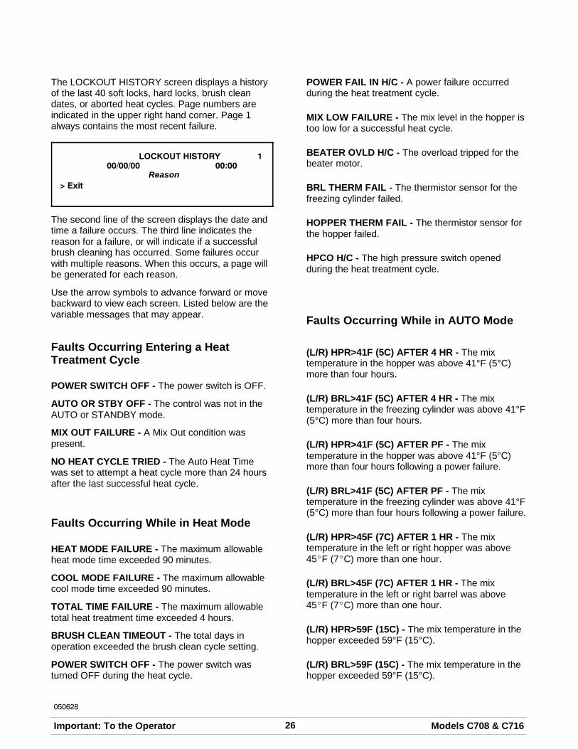
050628
The LOCKOUT HISTORY screen displays a historyof the last 40 soft locks, hard locks, brush cleandates, or aborted heat cycles. Page numbers areindicated in the upper right hand corner. Page 1always contains the most recent failure.
LOCKOUT HISTORY 100/00/00 00:00
Reason> Exit
The second line of the screen displays the date andtime a failure occurs. The third line indicates thereason for a failure, or will indicate if a successfulbrush cleaning has occurred. Some failures occurwith multiple reasons. When this occurs, a page willbe generated for each reason.
Use the arrow symbols to advance forward or movebackward to view each screen. Listed below are thevariable messages that may appear.
Faults Occurring Entering a HeatTreatment Cycle
POWER SWITCH OFF - The power switch is OFF.
AUTO OR STBY OFF - The control was not in theAUTO or STANDBY mode.
MIX OUT FAILURE - A Mix Out condition waspresent.
NO HEAT CYCLE TRIED - The Auto Heat Timewas set to attempt a heat cycle more than 24 hoursafter the last successful heat cycle.
Faults Occurring While in Heat Mode
HEAT MODE FAILURE - The maximum allowableheat mode time exceeded 90 minutes.
COOL MODE FAILURE - The maximum allowablecool mode time exceeded 90 minutes.
TOTAL TIME FAILURE - The maximum allowabletotal heat treatment time exceeded 4 hours.
BRUSH CLEAN TIMEOUT - The total days inoperation exceeded the brush clean cycle setting.
POWER SWITCH OFF - The power switch wasturned OFF during the heat cycle.
POWER FAIL IN H/C - A power failure occurredduring the heat treatment cycle.
MIX LOW FAILURE - The mix level in the hopper istoo low for a successful heat cycle.
BEATER OVLD H/C - The overload tripped for thebeater motor.
BRL THERM FAIL - The thermistor sensor for thefreezing cylinder failed.
HOPPER THERM FAIL - The thermistor sensor forthe hopper failed.
HPCO H/C - The high pressure switch openedduring the heat treatment cycle.
Faults Occurring While in AUTO Mode
(L/R) HPR>41F (5C) AFTER 4 HR - The mixtemperature in the hopper was above 41°F (5°C)more than four hours.
(L/R) BRL>41F (5C) AFTER 4 HR - The mixtemperature in the freezing cylinder was above 41°F(5°C) more than four hours.
(L/R) HPR>41F (5C) AFTER PF - The mixtemperature in the hopper was above 41°F (5°C)more than four hours following a power failure.
(L/R) BRL>41F (5C) AFTER PF - The mixtemperature in the freezing cylinder was above 41°F(5°C) more than four hours following a power failure.
(L/R) HPR>45F (7C) AFTER 1 HR - The mixtemperature in the left or right hopper was above45_F (7_C) more than one hour.
(L/R) BRL>45F (7C) AFTER 1 HR - The mixtemperature in the left or right barrel was above45_F (7_C) more than one hour.
(L/R) HPR>59F (15C) - The mix temperature in thehopper exceeded 59°F (15°C).
(L/R) BRL>59F (15C) - The mix temperature in thehopper exceeded 59°F (15°C).
27Models C708 & C716 Important: To the Operator050628
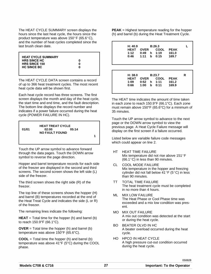
The HEAT CYCLE SUMMARY screen displays thehours since the last heat cycle, the hours since theproduct temperature was above 150_F (65.6_C),and the number of heat cycles completed since thelast brush clean date.
HEAT CYCLE SUMMARYHRS SINCE HC 0HRS SINCE 150 0HC SINCE BC 0
The HEAT CYCLE DATA screen contains a recordof up to 366 heat treatment cycles. The most recentheat cycle data will be shown first.
Each heat cycle record has three screens. The firstscreen displays the month and day of the heat cycle,the start time and end time, and the fault description.The bottom line displays the record number andindicates if a power failure occurred during the heatcycle (POWER FAILURE IN HC).
HEAT TREAT CYCLE01/01 02:00 05:14
NO FAULT FOUND1
Touch the UP arrow symbol to advance forwardthrough the data pages. Touch the DOWN arrowsymbol to reverse the page direction.
Hopper and barrel temperature records for each sideof the freezer are displayed in the second and thirdscreens. The second screen shows the left side (L)side of the freezer.
The third screen shows the right side (R) of thefreezer.
The top line of these screens shows the hopper (H)and barrel (B) temperatures recorded at the end ofthe Heat Treat Cycle and indicates the side (L or R)of the freezer.
The remaining lines indicate the following:
HEAT = Total time for the hopper (h) and barrel (b)to reach 150.9°F (66.1°C).
OVER = Total time the hopper (h) and barrel (b)temperature was above 150°F (65.6°C).
COOL = Total time the hopper (h) and barrel (b)temperature was above 41°F (5°C) during the COOLphase.
PEAK = Highest temperature reading for the hopper(h) and barrel (b) during the Heat Treatment Cycle.
H: 40.9 B:26.3 LHEAT OVER COOL PEAK1:12 0:49 h 1:19 161.00:46 1:11 b 0:15 169.7
H: 38.0 B:23.7 RHEAT OVER COOL PEAK1:09 0:52 h 1:11 161.20:66 1:00 b 0:11 169.9
The HEAT time indicates the amount of time takenin each zone to reach 150.9°F (66.1°C). Each zonemust remain above 150°F (65.6°C) for a minimum of35 minutes.
Touch the UP arrow symbol to advance to the nextpage or the DOWN arrow symbol to view theprevious page. A Heat Cycle Failure message willdisplay on the first screen if a failure occurred.
Listed below are variable failure code messageswhich could appear on line 2.
HT HEAT TIME FAILUREMix temperature did not rise above 151_F(66.1_C) in less than 90 minutes.
CL COOL MODE FAILUREMix temperature in the hopper and freezingcylinder did not fall below 41_F (5_C) in lessthan 90 minutes.
TT TOTAL TIME FAILUREThe heat treatment cycle must be completedin no more than 4 hours.
ML MIX LOW FAILUREThe Heat Phase or Cool Phase time wasexceeded and a mix low condition was pres-ent.
MO MIX OUT FAILUREA mix out condition was detected at the startor during the heat cycle.
BO BEATER OLVD IN HCA beater overload occurred during the heatcycle.
HO HPCO IN HEAT CYCLEA high pressure cut-out condition occurredduring the heat cycle.
28 Models C708 & C716Important: To the Operator
081111
PF POWER FAILURE IN HCA power failure caused the Heat Phase,Cool Phase, or Total Cycle Time to exceedthe maximum allowed time. If a power failureoccurs, but the heat treatment cycle doesnot fail, an asterisk(*) will appear on the thirdline of the display.
OP OPERATOR INTERRUPTIndicates the heat cycle was aborted in theOPERATOR INTERRUPT option in the Ser-vice Menu.
PS POWER SWITCH OFFThe power switch was placed into the OFFposition during the heat cycle.
TH THERMISTOR FAILUREA thermistor probe has failed.
PD PRODUCT DOOR OFFA product door is not in place or is loose.
The SYSTEM INFORMATION is displayed on threeseparate screens. The first screen contains thecontrol and software version installed in themachine.
SOFTWARE VERSIONC708 CONTROL UVC3VERSION 1.07> Next
Touch the SEL symbol to advance to the nextsystem information screen containing the softwarelanguage version.
LanguageV2.00 English 621
> Next
Touch the SEL symbol to advance to the thirdsystem information screen containing the model billof material and machine serial number. Touching theSEL symbol again will return to the Menu list.
B.O.M. C70827C000S/N K0000000
> Next
The CURRENT CONDITIONS screen provides theviscosity readings for the product when the machineis running, and the hopper and the freezing cylindertemperatures for the machine.
VISC 0.0HOPPER 41.0
CURRENT CONDITIONS is the only Menu screenthat will return the control panel keys to normaloperation. The Menu symbols will not be lit whenthis option is selected but the panel touch keys arefully functional. Exit the CURRENT CONDITIONSscreen and return to the Menu by touching the SELsymbol.
29Models C708 & C716 Operating Procedures
Section 6 Operating Procedures
The C708 stores mix in a hopper and has a 3.4quart (3.2 liter) capacity freezing cylinder with asingle spout door. The C716 stores mix in twohoppers and has two 3.4 quart (3.2 liter) capacityfreezing cylinders with a three spout door.
The Model C708 has been selected to illustrate thestep-by-step operating procedures. Duplicate theprocedures, where they apply, for the secondfreezing cylinder on the Model C716.
We begin our instructions at the point where weenter the store in the morning and find the partsdisassembled and laid out to air dry from theprevious night's cleaning.
These opening procedures will show you how toassemble these parts into the freezer, sanitize them,and prime the freezer with fresh mix in preparationto serve your first portion.
If you are disassembling the machine for the firsttime or need information to get to this starting pointin our instructions, turn to page 44, “Disassembly”,and start there.
Freezing Cylinder Assembly
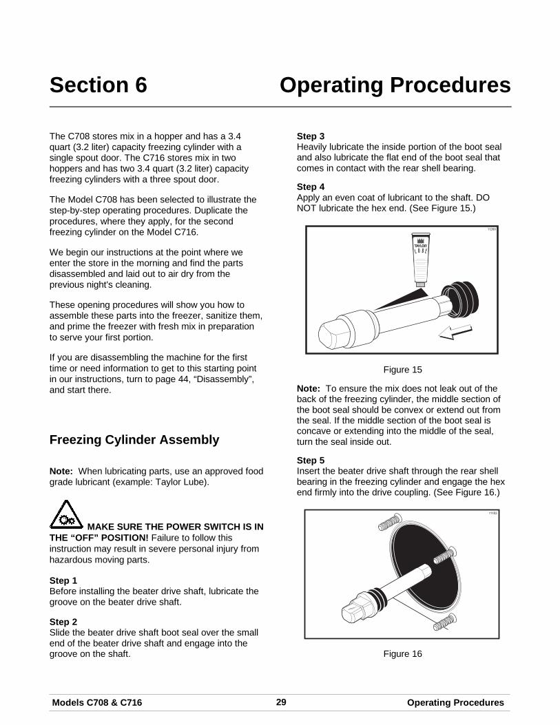
Note: When lubricating parts, use an approved foodgrade lubricant (example: Taylor Lube).
MAKE SURE THE POWER SWITCH IS INTHE “OFF” POSITION! Failure to follow thisinstruction may result in severe personal injury fromhazardous moving parts.
Step 1Before installing the beater drive shaft, lubricate thegroove on the beater drive shaft.
Step 2Slide the beater drive shaft boot seal over the smallend of the beater drive shaft and engage into thegroove on the shaft.
Step 3Heavily lubricate the inside portion of the boot sealand also lubricate the flat end of the boot seal thatcomes in contact with the rear shell bearing.
Step 4Apply an even coat of lubricant to the shaft. DONOT lubricate the hex end. (See Figure 15.)
R
11269
Figure 15
Note: To ensure the mix does not leak out of theback of the freezing cylinder, the middle section ofthe boot seal should be convex or extend out fromthe seal. If the middle section of the boot seal isconcave or extending into the middle of the seal,turn the seal inside out.
Step 5Insert the beater drive shaft through the rear shellbearing in the freezing cylinder and engage the hexend firmly into the drive coupling. (See Figure 16.)
Figure 16
30 Models C708 & C716Operating Procedures
USE EXTREME CAUTION when handlingthe beater assembly. The scraper blades are verysharp and may cause injury.
Step 6Before installing the beater assembly, check thescraper blades for any nicks or signs of wear. If anynicks are present, or if the blades are worn, replaceboth blades.
If the blades are in good condition, install thescraper blade clips over the scraper blades. Placethe rear scraper blade over the rear holding pin onthe beater. (See Figure 17.)
11271
Figure 17
Note: Scraper blades should be replaced every 3months.
Note: The hole on the scraper blade must fitsecurely over the pin to prevent costly damage.
Step 7Holding the rear blade on the beater, slide it into thefreezing cylinder halfway. Install the front scraperblade over the front holding pin. (See Figure 18.)
11249
Figure 18
Step 8Install the beater shoes. (See Figure 19.)
Figure 19
Step 9Slide the beater assembly the rest of the way intothe freezing cylinder.
Make sure the beater assembly is in position overthe drive shaft by turning the beater slightly until thebeater is properly seated. When in position, thebeater will not protrude beyond the front of thefreezing cylinder. (See Figure 20.)
11250
Figure 20
Repeat these steps for the other side of theModel C716.
31Models C708 & C716 Operating Procedures
Freezer Door AssemblyThe assembly of the C708 freezer door is differentfrom the C716 freezer door. Please follow theappropriate instructions for your machine.
Model C708 Freezer Door AssemblyStep 1Place the door gasket into the groove on the back ofthe freezer door. Slide the front bearing over thebaffle rod so the flanged edge is against the door.DO NOT lubricate the gasket or bearing.(See Figure 21.)
Figure 21Step 2Slide the three o-rings into the grooves on the drawvalve and lubricate. (See Figure 22.)
10423
Figure 22
Step 3Lightly lubricate the inside of the top of the freezerdoor valve cavity. (See Figure 23.)
Figure 23
Step 4Insert the draw valve from the top, with the drawhandle slot facing forward. (See Figure 24.)
Figure 24
32 Models C708 & C716Operating Procedures
Model C708 Freezer Door Assembly (Cont'd.)
Step 5Insert the baffle rod through the beater in thefreezing cylinder. With the door seated on thefreezer studs, install the handscrews, with the longerones on top. Tighten equally in a criss-cross patternto insure the door is snug. (See Figure 25.)
Figure 25
Step 6Slide the fork of the draw handle into the slot of thedraw valve. Secure with pivot pin. (See Figure 26.)
Figure 26
Note: The C708 features an adjustable draw handleto provide portion control, giving a better consistentquality to your product and controlling costs.
The draw handle should be adjusted to provide aflow rate of 5 to 7-1/2 oz. (142 g. to 213 g.) ofproduct by weight per 10 seconds. To INCREASEthe flow rate, turn the adjustment screwCLOCKWISE. Turn the adjustment screwCOUNTER-CLOCKWISE to DECREASE the flowrate.
Step 7Slide the two drip pans into the holes in the left andrear panels. (See Figure 31.)
Figure 27
Step 8Install the front drip tray and splash shield under thedoor spout. (See Figure 32.)
Figure 28
33Models C708 & C716 Operating Procedures
Model C716 Freezer Door Assembly
Step 1Place the door gaskets into the grooves on the backof the freezer door.
Step 2Slide the front bearings over the baffle rods. Theflanged edges should be against the door. DO NOTlubricate the gaskets or bearings.
Step 3Insert the baffle rods through the beaters in thefreezing cylinders. With the door seated on thefreezer studs, install the handscrews, with the longerones on top. Tighten equally in a criss-cross patternto insure the door is snug.
Figure 29
Step 4Slide the three o-rings into the grooves of eachstandard draw valve. Slide the H-ring and o-ring intothe grooves of the center draw valve. Lubricate theH-ring and o-rings.
Step 5Lubricate the inside of the freezer door spouts, topand bottom.
Step 6Insert the draw valves from the bottom until the slotin each draw valve comes into view.
Figure 30
Step 7Position each draw handle with the adjustmentscrew facing down. Slide the fork of each drawhandle into the slot of each draw valve, starting fromthe right.
Step 8Slide the pivot pin through the draw handles as thehandles are inserted into the draw valves
Note: This freezer features adjustable draw handlesto provide portion control, giving a better consistentquality to your product and controlling costs. Thedraw handles should be adjusted to provide a flowrate of 5 to 7-1/2 oz. (142 g. to 213 g.) of product byweight per 10 seconds.
34 Models C708 & C716Operating Procedures
To INCREASE the flow rate, turn the adjustmentscrew CLOCKWISE. To DECREASE the flow rate,turn the adjustment screw COUNTER-CLOCKWISE.
Step 9Snap the design caps over the bottom of the doorspouts.
Step 10Slide the two rear drip trays into the holes in theback panel. Slide the two drip pans into the holes inthe side panels. (See Figure 31.)
Figure 31
Step 11Install the front drip tray and splash shield under thedoor spouts. (See Figure 32.)
Figure 32
Mix Pump Assembly
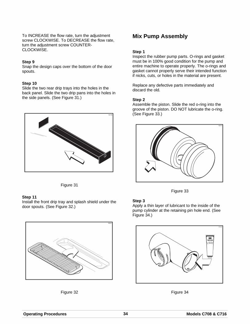
Step 1Inspect the rubber pump parts. O-rings and gasketmust be in 100% good condition for the pump andentire machine to operate properly. The o-rings andgasket cannot properly serve their intended functionif nicks, cuts, or holes in the material are present.
Replace any defective parts immediately anddiscard the old.
Step 2Assemble the piston. Slide the red o-ring into thegroove of the piston. DO NOT lubricate the o-ring.(See Figure 33.)
Figure 33
Step 3Apply a thin layer of lubricant to the inside of thepump cylinder at the retaining pin hole end. (SeeFigure 34.)
15130
L U B E
R
Figure 34
35Models C708 & C716 Operating Procedures
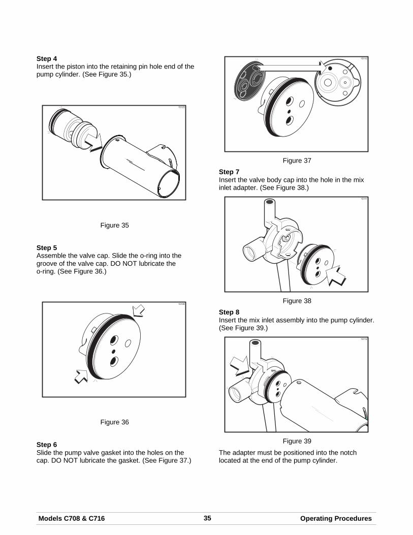
Step 4Insert the piston into the retaining pin hole end of thepump cylinder. (See Figure 35.)
15123
Figure 35
Step 5Assemble the valve cap. Slide the o-ring into thegroove of the valve cap. DO NOT lubricate theo-ring. (See Figure 36.)
15109
Figure 36
Step 6Slide the pump valve gasket into the holes on thecap. DO NOT lubricate the gasket. (See Figure 37.)
15110
Figure 37
Step 7Insert the valve body cap into the hole in the mixinlet adapter. (See Figure 38.)
15111
Figure 38
Step 8Insert the mix inlet assembly into the pump cylinder.(See Figure 39.)
15112
Figure 39
The adapter must be positioned into the notchlocated at the end of the pump cylinder.
36 Models C708 & C716Operating Procedures
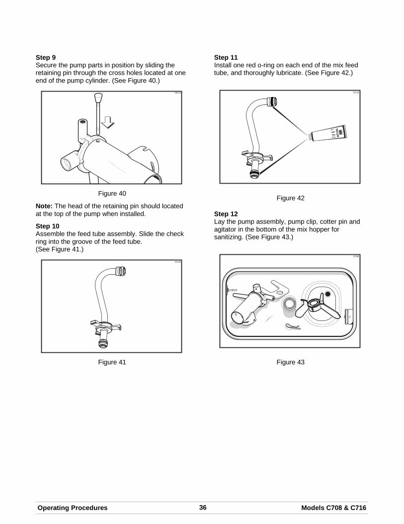
Step 9Secure the pump parts in position by sliding theretaining pin through the cross holes located at oneend of the pump cylinder. (See Figure 40.)
15113
Figure 40
Note: The head of the retaining pin should locatedat the top of the pump when installed.
Step 10Assemble the feed tube assembly. Slide the checkring into the groove of the feed tube.(See Figure 41.)
15133
Figure 41
Step 11Install one red o-ring on each end of the mix feedtube, and thoroughly lubricate. (See Figure 42.)
15132
Figure 42
Step 12Lay the pump assembly, pump clip, cotter pin andagitator in the bottom of the mix hopper forsanitizing. (See Figure 43.)
12166
Figure 43
37Models C708 & C716 Operating Procedures080617
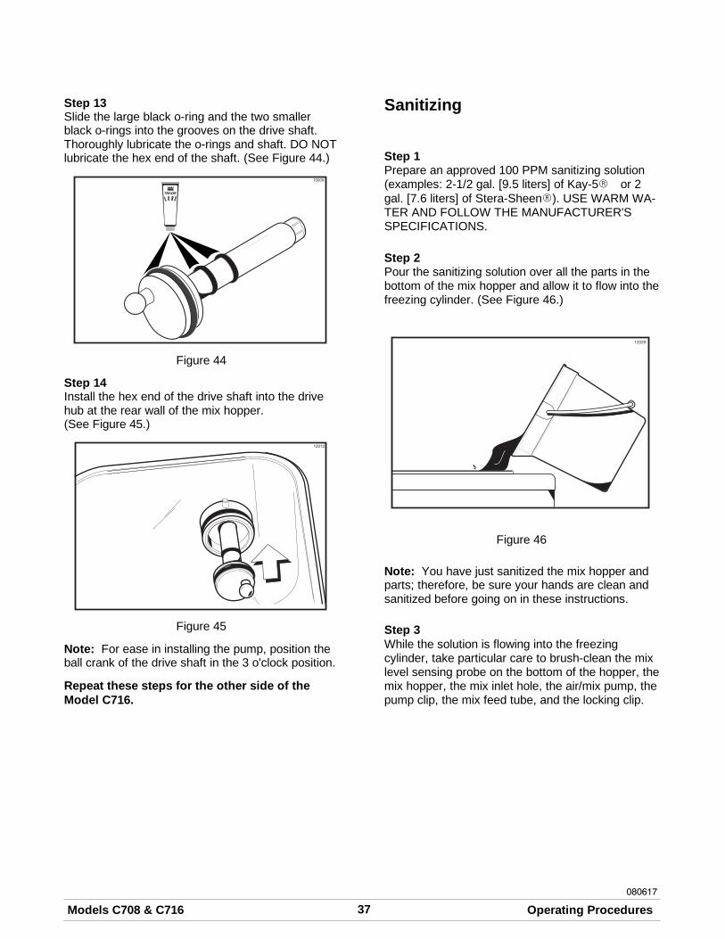
Step 13Slide the large black o-ring and the two smallerblack o-rings into the grooves on the drive shaft.Thoroughly lubricate the o-rings and shaft. DO NOTlubricate the hex end of the shaft. (See Figure 44.)
Figure 44
Step 14Install the hex end of the drive shaft into the drivehub at the rear wall of the mix hopper.(See Figure 45.)
Figure 45
Note: For ease in installing the pump, position theball crank of the drive shaft in the 3 o'clock position.
Repeat these steps for the other side of theModel C716.
Sanitizing
Step 1Prepare an approved 100 PPM sanitizing solution(examples: 2-1/2 gal. [9.5 liters] of Kay-5R or 2gal. [7.6 liters] of Stera-SheenR). USE WARM WA-TER AND FOLLOW THE MANUFACTURER'SSPECIFICATIONS.
Step 2Pour the sanitizing solution over all the parts in thebottom of the mix hopper and allow it to flow into thefreezing cylinder. (See Figure 46.)
Figure 46
Note: You have just sanitized the mix hopper andparts; therefore, be sure your hands are clean andsanitized before going on in these instructions.
Step 3While the solution is flowing into the freezingcylinder, take particular care to brush-clean the mixlevel sensing probe on the bottom of the hopper, themix hopper, the mix inlet hole, the air/mix pump, thepump clip, the mix feed tube, and the locking clip.
38 Models C708 & C716Operating Procedures
080617
Step 4Install the pump assembly at the rear of the mixhopper. To position the pump on the drive hub, alignthe drive hole in the piston with the drive crank ofthe drive shaft. Secure the pump in place by slippingthe pump clip over the collar of the pump, makingsure the clip fits into the grooves in the collar.(See Figure 47.)
Figure 47
Step 5
Install the pump end of the mix feedtube and secure with the cotter pin. Failure tofollow this instruction could result in sanitizerspraying on the operator. (See Figure 48.)
12185
Figure 48
Step 6Prepare another pail of approved 100 PPM sanitiz-ing solution (examples: 2-1/2 gal. [9.5 liters] ofKay-5R or 2 gal. [7.6 liters] of Stera-SheenR).USE WARM WATER AND FOLLOW THEMANUFACTURER'S SPECIFICATIONS.
Step 7Pour the sanitizing solution into the mix hopper.
Step 8Brush the exposed sides of the hopper.
Step 9Place the power switch in the ON position.
Step 10Touch the WASH symbol . This will cause thesanitizing solution in the freezing cylinder to beagitated. Wait at least 5 minutes before proceedingwith these instructions.
Step 11With a pail beneath the door spout(s), open the drawvalve and touch the PUMP symbol . Open andclose the draw valve 6 times.
Note: Momentarily open the center draw valve tosanitize the center door spout (C716 only).
Draw off the remaining sanitizing solution.
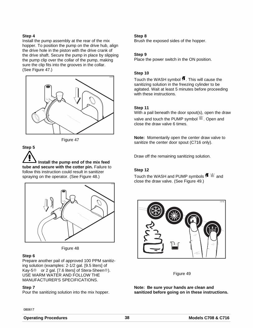
Step 12Touch the WASH and PUMP symbols andclose the draw valve. (See Figure 49.)
Figure 49
Note: Be sure your hands are clean andsanitized before going on in these instructions.
39Models C708 & C716 Operating Procedures
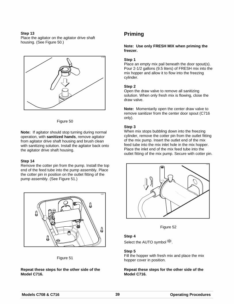
Step 13Place the agitator on the agitator drive shafthousing. (See Figure 50.)
12182
Figure 50
Note: If agitator should stop turning during normaloperation, with sanitized hands, remove agitatorfrom agitator drive shaft housing and brush cleanwith sanitizing solution. Install the agitator back ontothe agitator drive shaft housing.
Step 14Remove the cotter pin from the pump. Install the topend of the feed tube into the pump assembly. Placethe cotter pin in position on the outlet fitting of thepump assembly. (See Figure 51.)
Figure 51
Repeat these steps for the other side of theModel C716.
Priming
Note: Use only FRESH MIX when priming thefreezer.
Step 1Place an empty mix pail beneath the door spout(s).Pour 2-1/2 gallons (9.5 liters) of FRESH mix into themix hopper and allow it to flow into the freezingcylinder.
Step 2Open the draw valve to remove all sanitizingsolution. When only fresh mix is flowing, close thedraw valve.
Note: Momentarily open the center draw valve toremove sanitizer from the center door spout (C716only).
Step 3When mix stops bubbling down into the freezingcylinder, remove the cotter pin from the outlet fittingof the mix pump. Insert the outlet end of the mixfeed tube into the mix inlet hole in the mix hopper.Place the inlet end of the mix feed tube into theoutlet fitting of the mix pump. Secure with cotter pin.
Figure 52
Step 4Select the AUTO symbol .
Step 5Fill the hopper with fresh mix and place the mixhopper cover in position.
Repeat these steps for the other side of theModel C716.
40 Models C708 & C716Operating Procedures
080222
Daily Closing ProceduresThis procedure must be performed oncedaily!
The function of the Heat Treatment Cycle is todestroy bacteria by raising the temperature of themix in the freezing cylinder and the hopper to aspecified temperature for a specified period of time,and then bringing the temperature back down lowenough to retard spoilage.The Heat Treatment Cycle will start at the timedesignated in the Auto Heat Time.
IMPORTANT: The level of mix in the hoppersmust be high enough to cover the agitatorpaddles. Note: If the BRUSH CLEAN COUNTERdisplay has counted down to one day, do not addmix. The machine must be disassembled and brushcleaned within 24 hours.
The freezer must be in the AUTO (AUTO symbol illuminated) or in the STANDBY mode (STANDBYsymbol illuminated) before the HEAT cycle maybe started.Step 1Remove the hopper cover(s).
MAKE SURE YOUR HANDS ARE CLEAN ANDSANITIZED BEFORE PERFORMING THESE NEXTSTEPS.
Step 2Remove the agitator(s) from the mix hopper(s).Step 3Remove the design caps (C716 only).Step 4Take the agitator(s), hopper cover(s) and designcap(s) to the sink for further cleaning and sanitizing.Step 5Rinse these parts in cool, clean water.Step 6Prepare a small amount of an approved 100 PPMcleaning/sanitizing solution (example: Kay-5® orStera-Sheen®). USE WARM WATER AND FOL-LOW THE MANUFACTURER'S SPECIFICATIONS.Brush clean the agitator(s) and the hopper cover(s).
Step 7Prepare a small amount of an approved 100 PPMcleaning/sanitizing solution (example: Kay-5® orStera-Sheen®). USE WARM WATER AND FOL-LOW THE MANUFACTURER'S SPECIFICATIONS.Sanitize the agitator(s) and hopper cover(s).
Step 8Install the agitator(s) back onto the agitator driveshaft housing(s). Replace the hopper cover(s).
IMPORTANT: If you do not install the agitator(s)correctly, the machine will fail the heat cycle andlock out in the morning.
Step 9Return to the freezer with a small amount ofcleaning solution. Dip the door spout brush into thecleaning solution and brush clean the door spout(s)and bottom of the draw valve(s).
Note: To assure sanitary conditions are maintained,brush each item for a total of 60 seconds, repeatedlydipping the brush in cleaning solution.(See Figure 53.)
Figure 53
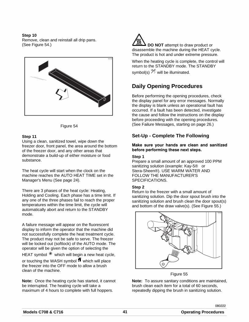
41Models C708 & C716 Operating Procedures080222
Step 10Remove, clean and reinstall all drip pans.(See Figure 54.)
Figure 54
Step 11Using a clean, sanitized towel, wipe down thefreezer door, front panel, the area around the bottomof the freezer door, and any other areas thatdemonstrate a build-up of either moisture or foodsubstance.
The heat cycle will start when the clock on themachine reaches the AUTO HEAT TIME set in theManager's Menu (See page 24).
There are 3 phases of the heat cycle: Heating,Holding and Cooling. Each phase has a time limit. Ifany one of the three phases fail to reach the propertemperatures within the time limit, the cycle willautomatically abort and return to the STANDBYmode.
A failure message will appear on the fluorescentdisplay to inform the operator that the machine didnot successfully complete the heat treatment cycle.The product may not be safe to serve. The freezerwill be locked out (softlock) of the AUTO mode. Theoperator will be given the option of selecting theHEAT symbol which will begin a new heat cycle,or touching the WASH symbol which will placethe freezer into the OFF mode to allow a brushclean of the machine.
Note: Once the heating cycle has started, it cannotbe interrupted. The heating cycle will take amaximum of 4 hours to complete with full hoppers.
DO NOT attempt to draw product ordisassemble the machine during the HEAT cycle.The product is hot and under extreme pressure.
When the heating cycle is complete, the control willreturn to the STANDBY mode. The STANDBYsymbol(s) will be illuminated.
Daily Opening ProceduresBefore performing the opening procedures, checkthe display panel for any error messages. Normallythe display is blank unless an operational fault hasoccurred. If a fault has been detected, investigatethe cause and follow the instructions on the displaybefore proceeding with the opening procedures.(See Failure Messages, starting on page 26.)
Set-Up - Complete The Following
Make sure your hands are clean and sanitizedbefore performing these next steps.
Step 1Prepare a small amount of an approved 100 PPMsanitizing solution (example: Kay-5® orStera-Sheen®). USE WARM WATER ANDFOLLOW THE MANUFACTURER'SSPECIFICATIONS.
Step 2Return to the freezer with a small amount ofsanitizing solution. Dip the door spout brush into thesanitizing solution and brush clean the door spout(s)and bottom of the draw valve(s). (See Figure 55.)
Figure 55
Note: To assure sanitary conditions are maintained,brush clean each item for a total of 60 seconds,repeatedly dipping the brush in sanitizing solution.
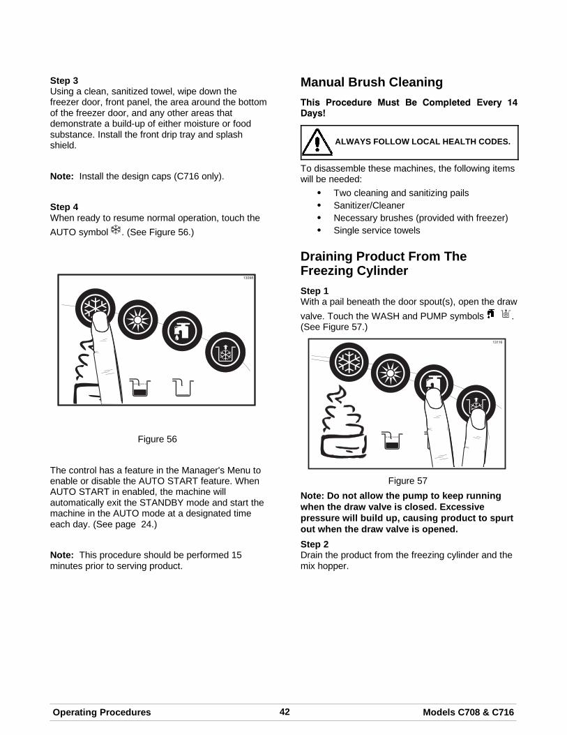
42 Models C708 & C716Operating Procedures
Step 3Using a clean, sanitized towel, wipe down thefreezer door, front panel, the area around the bottomof the freezer door, and any other areas thatdemonstrate a build-up of either moisture or foodsubstance. Install the front drip tray and splashshield.
Note: Install the design caps (C716 only).
Step 4When ready to resume normal operation, touch theAUTO symbol . (See Figure 56.)
Figure 56
The control has a feature in the Manager's Menu toenable or disable the AUTO START feature. WhenAUTO START in enabled, the machine willautomatically exit the STANDBY mode and start themachine in the AUTO mode at a designated timeeach day. (See page 24.)
Note: This procedure should be performed 15minutes prior to serving product.
Manual Brush CleaningThis Procedure Must Be Completed Every 14Days!
ALWAYS FOLLOW LOCAL HEALTH CODES.
To disassemble these machines, the following itemswill be needed:
S Two cleaning and sanitizing pailsS Sanitizer/CleanerS Necessary brushes (provided with freezer)S Single service towels
Draining Product From TheFreezing CylinderStep 1With a pail beneath the door spout(s), open the drawvalve. Touch the WASH and PUMP symbols .(See Figure 57.)
Figure 57Note: Do not allow the pump to keep runningwhen the draw valve is closed. Excessivepressure will build up, causing product to spurtout when the draw valve is opened.Step 2Drain the product from the freezing cylinder and themix hopper.
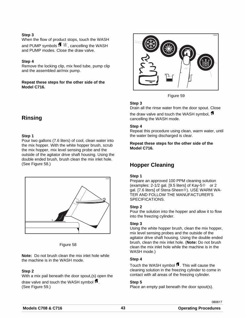
43Models C708 & C716 Operating Procedures080617
Step 3When the flow of product stops, touch the WASHand PUMP symbols , cancelling the WASHand PUMP modes. Close the draw valve.
Step 4Remove the locking clip, mix feed tube, pump clipand the assembled air/mix pump.
Repeat these steps for the other side of theModel C716.
Rinsing
Step 1Pour two gallons (7.6 liters) of cool, clean water intothe mix hopper. With the white hopper brush, scrubthe mix hopper, mix level sensing probe and theoutside of the agitator drive shaft housing. Using thedouble ended brush, brush clean the mix inlet hole.(See Figure 58.)
Figure 58
Note: Do not brush clean the mix inlet hole whilethe machine is in the WASH mode.
Step 2With a mix pail beneath the door spout,(s) open thedraw valve and touch the WASH symbol .(See Figure 59.)
Figure 59
Step 3Drain all the rinse water from the door spout. Closethe draw valve and touch the WASH symbol, cancelling the WASH mode.
Step 4Repeat this procedure using clean, warm water, untilthe water being discharged is clear.
Repeat these steps for the other side of theModel C716.
Hopper Cleaning
Step 1Prepare an approved 100 PPM cleaning solution(examples: 2-1/2 gal. [9.5 liters] of Kay-5R or 2gal. [7.6 liters] of Stera-SheenR). USE WARM WA-TER AND FOLLOW THE MANUFACTURER'SSPECIFICATIONS.
Step 2Pour the solution into the hopper and allow it to flowinto the freezing cylinder.
Step 3Using the white hopper brush, clean the mix hopper,mix level sensing probes and the outside of theagitator drive shaft housing. Using the double endedbrush, clean the mix inlet hole. (Note: Do not brushclean the mix inlet hole while the machine is in theWASH mode.)
Step 4Touch the WASH symbol . This will cause thecleaning solution in the freezing cylinder to come incontact with all areas of the freezing cylinder.
Step 5Place an empty pail beneath the door spout(s).
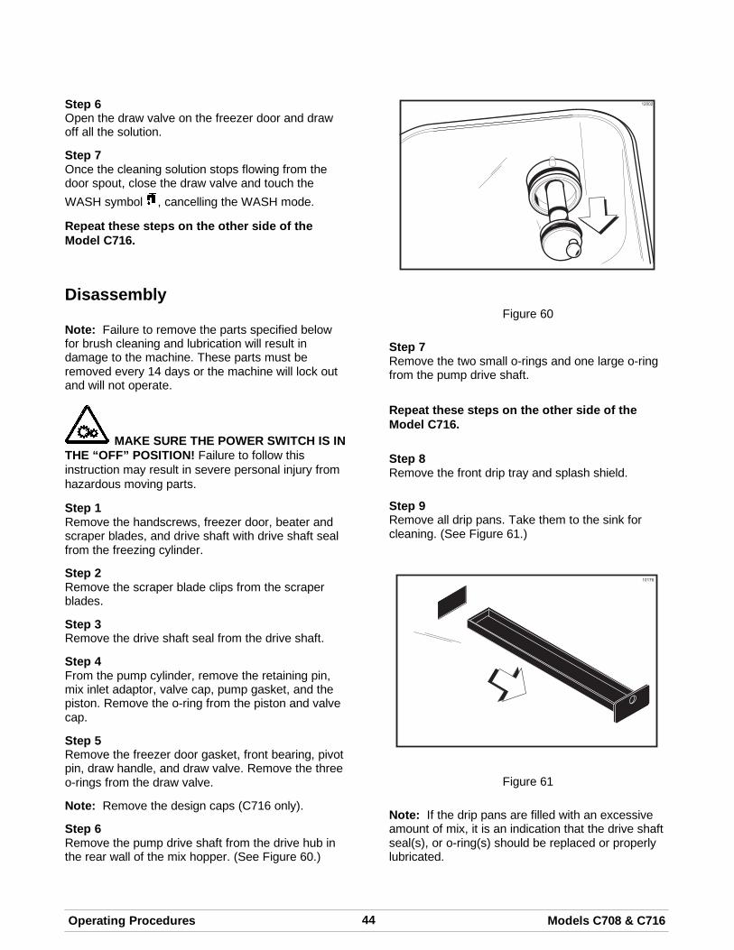
44 Models C708 & C716Operating Procedures
Step 6Open the draw valve on the freezer door and drawoff all the solution.
Step 7Once the cleaning solution stops flowing from thedoor spout, close the draw valve and touch theWASH symbol , cancelling the WASH mode.
Repeat these steps on the other side of theModel C716.
Disassembly
Note: Failure to remove the parts specified belowfor brush cleaning and lubrication will result indamage to the machine. These parts must beremoved every 14 days or the machine will lock outand will not operate.
MAKE SURE THE POWER SWITCH IS INTHE “OFF” POSITION! Failure to follow thisinstruction may result in severe personal injury fromhazardous moving parts.
Step 1Remove the handscrews, freezer door, beater andscraper blades, and drive shaft with drive shaft sealfrom the freezing cylinder.
Step 2Remove the scraper blade clips from the scraperblades.
Step 3Remove the drive shaft seal from the drive shaft.
Step 4From the pump cylinder, remove the retaining pin,mix inlet adaptor, valve cap, pump gasket, and thepiston. Remove the o-ring from the piston and valvecap.
Step 5Remove the freezer door gasket, front bearing, pivotpin, draw handle, and draw valve. Remove the threeo-rings from the draw valve.
Note: Remove the design caps (C716 only).
Step 6Remove the pump drive shaft from the drive hub inthe rear wall of the mix hopper. (See Figure 60.)
Figure 60
Step 7Remove the two small o-rings and one large o-ringfrom the pump drive shaft.
Repeat these steps on the other side of theModel C716.
Step 8Remove the front drip tray and splash shield.
Step 9Remove all drip pans. Take them to the sink forcleaning. (See Figure 61.)
Figure 61
Note: If the drip pans are filled with an excessiveamount of mix, it is an indication that the drive shaftseal(s), or o-ring(s) should be replaced or properlylubricated.
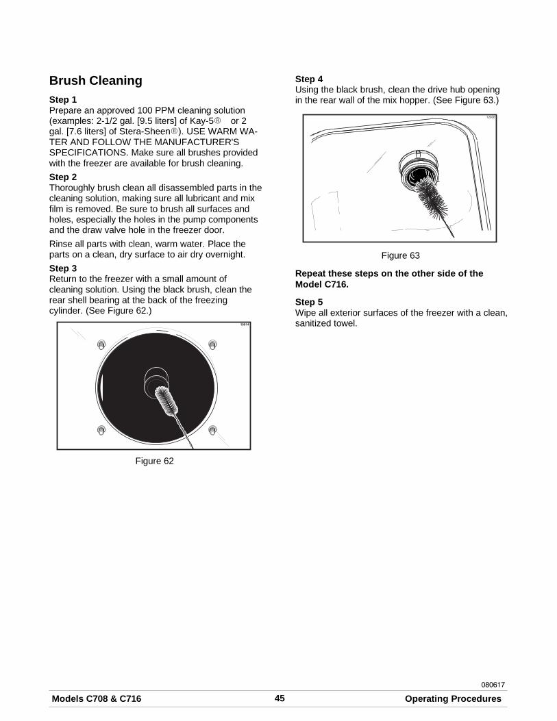
45Models C708 & C716 Operating Procedures080617
Brush CleaningStep 1Prepare an approved 100 PPM cleaning solution(examples: 2-1/2 gal. [9.5 liters] of Kay-5R or 2gal. [7.6 liters] of Stera-SheenR). USE WARM WA-TER AND FOLLOW THE MANUFACTURER'SSPECIFICATIONS. Make sure all brushes providedwith the freezer are available for brush cleaning.Step 2Thoroughly brush clean all disassembled parts in thecleaning solution, making sure all lubricant and mixfilm is removed. Be sure to brush all surfaces andholes, especially the holes in the pump componentsand the draw valve hole in the freezer door.Rinse all parts with clean, warm water. Place theparts on a clean, dry surface to air dry overnight.Step 3Return to the freezer with a small amount ofcleaning solution. Using the black brush, clean therear shell bearing at the back of the freezingcylinder. (See Figure 62.)
Figure 62
Step 4Using the black brush, clean the drive hub openingin the rear wall of the mix hopper. (See Figure 63.)
Figure 63
Repeat these steps on the other side of theModel C716.
Step 5Wipe all exterior surfaces of the freezer with a clean,sanitized towel.
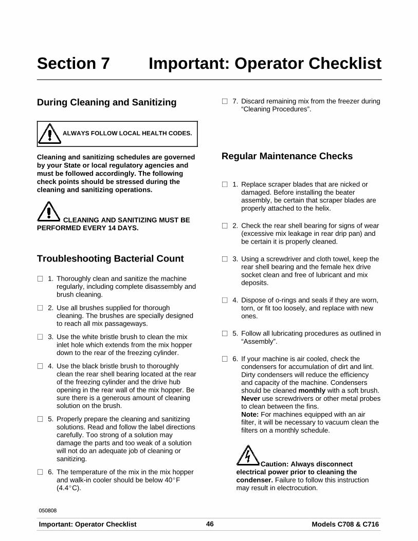
46 Models C708 & C716Important: Operator Checklist
050808
Section 7 Important: Operator Checklist
During Cleaning and Sanitizing
ALWAYS FOLLOW LOCAL HEALTH CODES.
Cleaning and sanitizing schedules are governedby your State or local regulatory agencies andmust be followed accordingly. The followingcheck points should be stressed during thecleaning and sanitizing operations.
CLEANING AND SANITIZING MUST BEPERFORMED EVERY 14 DAYS.
Troubleshooting Bacterial Count
j 1. Thoroughly clean and sanitize the machineregularly, including complete disassembly andbrush cleaning.
j 2. Use all brushes supplied for thoroughcleaning. The brushes are specially designedto reach all mix passageways.
j 3. Use the white bristle brush to clean the mixinlet hole which extends from the mix hopperdown to the rear of the freezing cylinder.
j 4. Use the black bristle brush to thoroughlyclean the rear shell bearing located at the rearof the freezing cylinder and the drive hubopening in the rear wall of the mix hopper. Besure there is a generous amount of cleaningsolution on the brush.
j 5. Properly prepare the cleaning and sanitizingsolutions. Read and follow the label directionscarefully. Too strong of a solution maydamage the parts and too weak of a solutionwill not do an adequate job of cleaning orsanitizing.
j 6. The temperature of the mix in the mix hopperand walk-in cooler should be below 40_F(4.4_C).
j 7. Discard remaining mix from the freezer during“Cleaning Procedures”.
Regular Maintenance Checks
j 1. Replace scraper blades that are nicked ordamaged. Before installing the beaterassembly, be certain that scraper blades areproperly attached to the helix.
j 2. Check the rear shell bearing for signs of wear(excessive mix leakage in rear drip pan) andbe certain it is properly cleaned.
j 3. Using a screwdriver and cloth towel, keep therear shell bearing and the female hex drivesocket clean and free of lubricant and mixdeposits.
j 4. Dispose of o-rings and seals if they are worn,torn, or fit too loosely, and replace with newones.
j 5. Follow all lubricating procedures as outlined in“Assembly”.
j 6. If your machine is air cooled, check thecondensers for accumulation of dirt and lint.Dirty condensers will reduce the efficiencyand capacity of the machine. Condensersshould be cleaned monthly with a soft brush.Never use screwdrivers or other metal probesto clean between the fins.Note: For machines equipped with an airfilter, it will be necessary to vacuum clean thefilters on a monthly schedule.
Caution: Always disconnectelectrical power prior to cleaning thecondenser. Failure to follow this instructionmay result in electrocution.
47Models C708 & C716 Important: Operator Checklist080222
j 7. If your machine is water cooled, check thewater lines for kinks or leaks. Kinks can occurwhen the machine is moved back and forth forcleaning or maintenance purposes.Deteriorated or cracked water lines should bereplaced only by an authorized Taylordistributor.
Winter Storage
If the place of business is to be closed during thewinter months, it is important to protect the freezerby following certain precautions, particularly if thebuilding is subject to freezing conditions.
Disconnect the freezer from the main power sourceto prevent possible electrical damage.
On water cooled freezers, disconnect the watersupply. Relieve pressure on the spring in the watervalve. Use air pressure on the outlet side to blow outany water remaining in the condenser. This isextremely important. Failure to follow thisprocedure may cause severe and costly damage tothe refrigeration system.
Your local Taylor Distributor can perform this winterstorage service for you.
Wrap detachable parts of the freezer such asbeater, blades, drive shaft, and freezer door, andplace them in a protected dry place. Rubber trimparts and gaskets can be protected by wrappingthem with moisture-proof paper. All parts should bethoroughly cleaned of dried mix or lubrication whichattract mice and other vermin.
It is recommended that an authorized servicetechnician perform winter storage draining, to insureall water has been removed. This will guard againstfreezing and rupturing of the components.
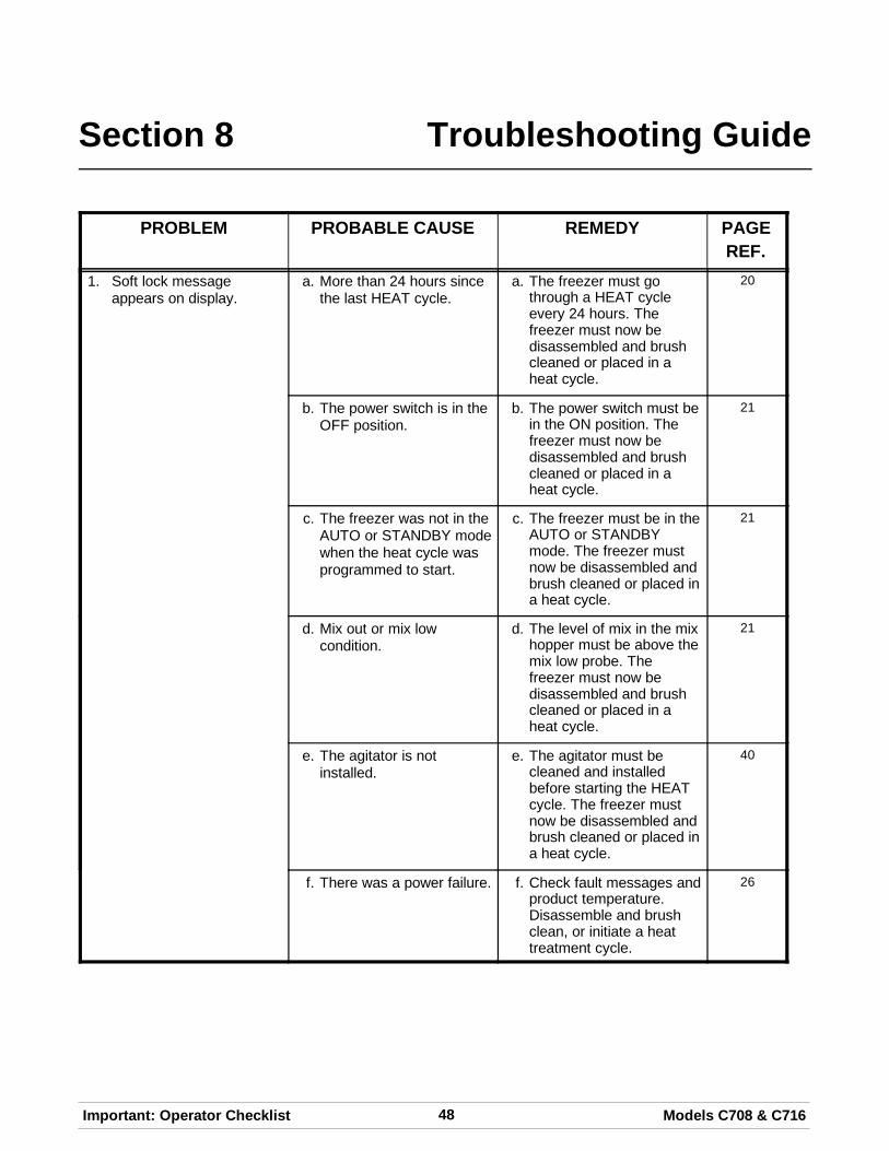
48 Models C708 & C716Important: Operator Checklist
Section 8 Troubleshooting Guide
PROBLEM PROBABLE CAUSE REMEDY PAGEREF.
1. Soft lock messageappears on display.
a. More than 24 hours sincethe last HEAT cycle.
a. The freezer must gothrough a HEAT cycleevery 24 hours. Thefreezer must now bedisassembled and brushcleaned or placed in aheat cycle.
20
b. The power switch is in theOFF position.
b. The power switch must bein the ON position. Thefreezer must now bedisassembled and brushcleaned or placed in aheat cycle.
21
c. The freezer was not in theAUTO or STANDBY modewhen the heat cycle wasprogrammed to start.
c. The freezer must be in theAUTO or STANDBYmode. The freezer mustnow be disassembled andbrush cleaned or placed ina heat cycle.
21
d. Mix out or mix lowcondition.
d. The level of mix in the mixhopper must be above themix low probe. Thefreezer must now bedisassembled and brushcleaned or placed in aheat cycle.
21
e. The agitator is notinstalled.
e. The agitator must becleaned and installedbefore starting the HEATcycle. The freezer mustnow be disassembled andbrush cleaned or placed ina heat cycle.
40
f. There was a power failure. f. Check fault messages andproduct temperature.Disassemble and brushclean, or initiate a heattreatment cycle.
26
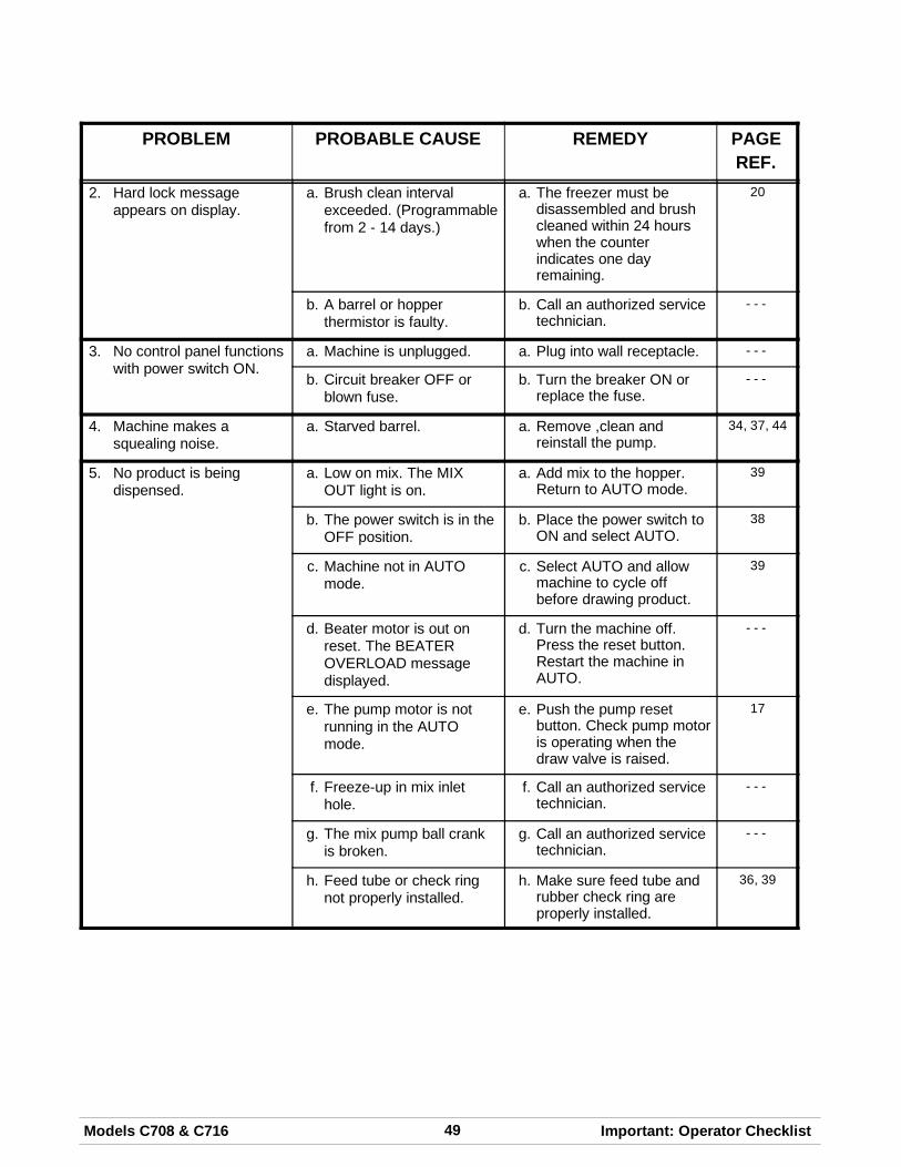
49Models C708 & C716 Important: Operator Checklist
PROBLEM PROBABLE CAUSE REMEDY PAGEREF.
2. Hard lock messageappears on display.
a. Brush clean intervalexceeded. (Programmablefrom 2 - 14 days.)
a. The freezer must bedisassembled and brushcleaned within 24 hourswhen the counterindicates one dayremaining.
20
b. A barrel or hopperthermistor is faulty.
b. Call an authorized servicetechnician.
- - -
3. No control panel functionswith power switch ON.
a. Machine is unplugged. a. Plug into wall receptacle. - - -
b. Circuit breaker OFF orblown fuse.
b. Turn the breaker ON orreplace the fuse.
- - -
4. Machine makes asquealing noise.
a. Starved barrel. a. Remove ,clean andreinstall the pump.
34, 37, 44
5. No product is beingdispensed.
a. Low on mix. The MIXOUT light is on.
a. Add mix to the hopper.Return to AUTO mode.
39
b. The power switch is in theOFF position.
b. Place the power switch toON and select AUTO.
38
c. Machine not in AUTOmode.
c. Select AUTO and allowmachine to cycle offbefore drawing product.
39
d. Beater motor is out onreset. The BEATEROVERLOAD messagedisplayed.
d. Turn the machine off.Press the reset button.Restart the machine inAUTO.
- - -
e. The pump motor is notrunning in the AUTOmode.
e. Push the pump resetbutton. Check pump motoris operating when thedraw valve is raised.
17
f. Freeze-up in mix inlethole.
f. Call an authorized servicetechnician.
- - -
g. The mix pump ball crankis broken.
g. Call an authorized servicetechnician.
- - -
h. Feed tube or check ringnot properly installed.
h. Make sure feed tube andrubber check ring areproperly installed.
36, 39
50 Models C708 & C716Important: Operator Checklist
PROBLEM PROBABLE CAUSE REMEDY PAGEREF.
6. The product is too soft. a. Draw rate is set too fast. a. Adjust draw rate of 5 to 71/2 oz. (142 g. to 213 g.)of product by weight in 10seconds.
17
7. The product is too thick. a. Freezing cylinder notprimed correctly.
a. Drain the freezing cylinderand reprime the machine.
39
b. Air/mix pump incorrectlyassembled.
b. Follow assemblyprocedures carefully.
34
c. The viscosity control is settoo cold.
c. Call an authorized servicetechnician.
- - -
d. Freeze-up in mix inlethole.
d. Call an authorized servicetechnician.
- - -
e. Butterfat is in the pump. e. Disassemble , clean andreinstall the pump.
34, 37, 44
8. The mix in the hopper istoo warm.
a. Hopper cover is not inposition.
a. Clean and sanitize hoppercover and place inposition.
40
b. The agitator is notinstalled.
b. Clean and sanitize theagitator and install.
40
c. The hopper temperature isout of adjustment.
c. Call an authorized servicetechnician.
- - -
9. The mix in the hopper istoo cold.
a. The hopper temperature isout of adjustment.
a. Call an authorized servicetechnician.
- - -
10. Mix Low and Mix Outprobes are notfunctioning.
a. Milkstone build-up in thehopper.
a. Clean hoppers thoroughly. 45
11. Product is collecting ontop of the freezer door.
a. The top o-ring on drawvalve is improperlylubricated or worn.
a. Lubricate properly orreplace the o-ring.
33
12. Excessive mix leakagefrom the bottom of doorspout.
a. Bottom o-ring on drawvalve is improperlylubricated or worn.
a. Lubricate properly orreplace the o-ring.
33
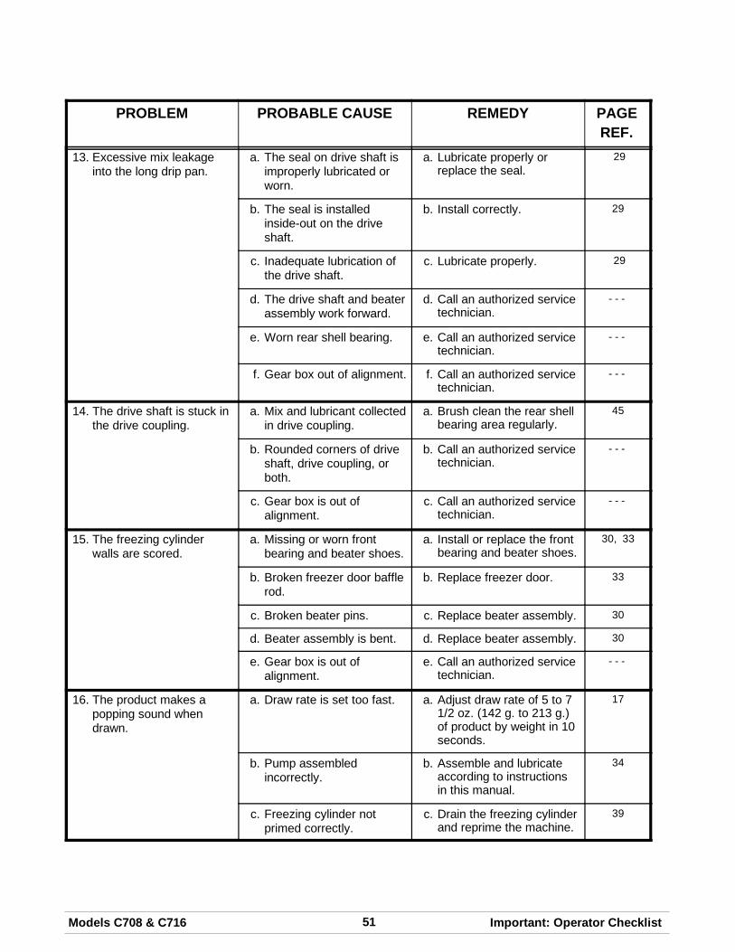
51Models C708 & C716 Important: Operator Checklist
PROBLEM PROBABLE CAUSE REMEDY PAGEREF.
13. Excessive mix leakageinto the long drip pan.
a. The seal on drive shaft isimproperly lubricated orworn.
a. Lubricate properly orreplace the seal.
29
b. The seal is installedinside-out on the driveshaft.
b. Install correctly. 29
c. Inadequate lubrication ofthe drive shaft.
c. Lubricate properly. 29
d. The drive shaft and beaterassembly work forward.
d. Call an authorized servicetechnician.
- - -
e. Worn rear shell bearing. e. Call an authorized servicetechnician.
- - -
f. Gear box out of alignment. f. Call an authorized servicetechnician.
- - -
14. The drive shaft is stuck inthe drive coupling.
a. Mix and lubricant collectedin drive coupling.
a. Brush clean the rear shellbearing area regularly.
45
b. Rounded corners of driveshaft, drive coupling, orboth.
b. Call an authorized servicetechnician.
- - -
c. Gear box is out ofalignment.
c. Call an authorized servicetechnician.
- - -
15. The freezing cylinderwalls are scored.
a. Missing or worn frontbearing and beater shoes.
a. Install or replace the frontbearing and beater shoes.
30, 33
b. Broken freezer door bafflerod.
b. Replace freezer door. 33
c. Broken beater pins. c. Replace beater assembly. 30
d. Beater assembly is bent. d. Replace beater assembly. 30
e. Gear box is out ofalignment.
e. Call an authorized servicetechnician.
- - -
16. The product makes apopping sound whendrawn.
a. Draw rate is set too fast. a. Adjust draw rate of 5 to 71/2 oz. (142 g. to 213 g.)of product by weight in 10seconds.
17
b. Pump assembledincorrectly.
b. Assemble and lubricateaccording to instructionsin this manual.
34
c. Freezing cylinder notprimed correctly.
c. Drain the freezing cylinderand reprime the machine.
39
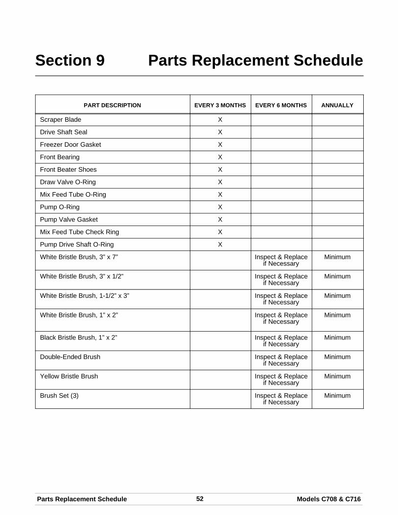
52 Models C708 & C716Parts Replacement Schedule
Section 9 Parts Replacement Schedule
PART DESCRIPTION EVERY 3 MONTHS EVERY 6 MONTHS ANNUALLY
Scraper Blade X
Drive Shaft Seal X
Freezer Door Gasket X
Front Bearing X
Front Beater Shoes X
Draw Valve O-Ring X
Mix Feed Tube O-Ring X
Pump O-Ring X
Pump Valve Gasket X
Mix Feed Tube Check Ring X
Pump Drive Shaft O-Ring X
White Bristle Brush, 3” x 7” Inspect & Replaceif Necessary
Minimum
White Bristle Brush, 3” x 1/2” Inspect & Replaceif Necessary
Minimum
White Bristle Brush, 1-1/2” x 3” Inspect & Replaceif Necessary
Minimum
White Bristle Brush, 1” x 2” Inspect & Replaceif Necessary
Minimum
Black Bristle Brush, 1” x 2” Inspect & Replaceif Necessary
Minimum
Double-Ended Brush Inspect & Replaceif Necessary
Minimum
Yellow Bristle Brush Inspect & Replaceif Necessary
Minimum
Brush Set (3) Inspect & Replaceif Necessary
Minimum
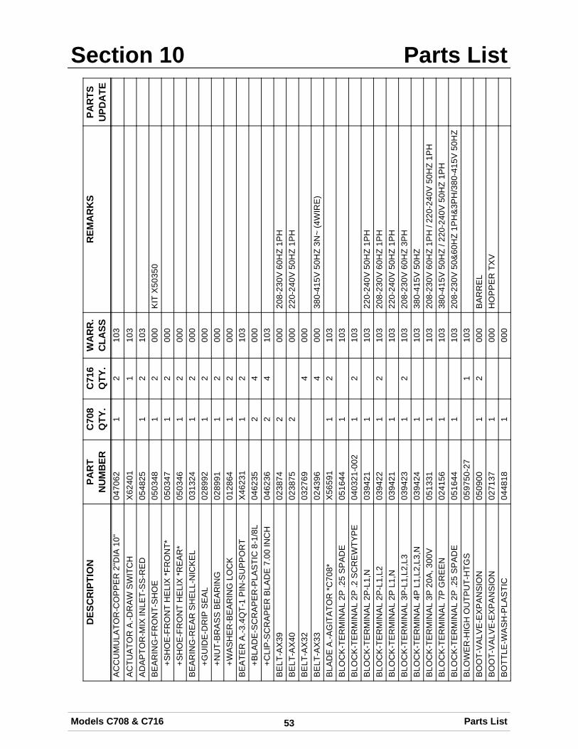
Section 10 Parts List
53Models C708 & C716 Parts List
DES
CR
IPTI
ON
PAR
TN
UM
BER
C70
8Q
TY.
C71
6Q
TY.
WA
RR
.C
LASS
REM
AR
KS
PAR
TSU
PDA
TEA
CC
UM
ULA
TOR
-CO
PP
ER
2"D
IA10
"04
7062
12
103
AC
TUA
TOR
A.-D
RA
WS
WIT
CH
X62
401
110
3A
DA
PTO
R-M
IXIN
LET-
SS
-RE
D05
4825
12
103
BE
AR
ING
-FR
ON
T-S
HO
E05
0348
12
000
KIT
X50
350
+SH
OE
-FR
ON
TH
ELI
X*F
RO
NT*
0503
471
200
0+S
HO
E-F
RO
NT
HE
LIX
*RE
AR
*05
0346
12
000
BE
AR
ING
-RE
AR
SH
ELL
-NIC
KE
L03
1324
12
000
+GU
IDE
-DR
IPS
EA
L02
8992
12
000
+NU
T-B
RA
SS
BE
AR
ING
0289
911
200
0+W
AS
HE
R-B
EA
RIN
GLO
CK
0128
641
200
0B
EA
TER
A.-3
.4Q
T-1
PIN
-SU
PP
OR
TX
4623
11
210
3+B
LAD
E-S
CR
AP
ER
-PLA
STI
C8-
1/8L
0462
352
400
0+C
LIP
-SC
RA
PE
RB
LAD
E7.
00IN
CH
0462
362
410
3B
ELT
-AX
3902
3874
200
020
8-23
0V60
HZ
1PH
BE
LT-A
X40
0238
752
000
220-
240V
50H
Z1P
HB
ELT
-AX
3203
2769
400
0B
ELT
-AX
3302
4396
400
038
0-41
5V50
HZ
3N~
(4W
IRE
)B
LAD
EA
.-AG
ITA
TOR
*C70
8*X
5659
11
210
3B
LOC
K-T
ER
MIN
AL
2P.2
5S
PA
DE
0516
441
103
BLO
CK
-TE
RM
INA
L2P
.2S
CR
EW
TYP
E04
0321
-002
12
103
BLO
CK
-TE
RM
INA
L2P
-L1,
N03
9421
110
322
0-24
0V50
HZ
1PH
BLO
CK
-TE
RM
INA
L2P
-L1,
L203
9422
12
103
208-
230V
60H
Z1P
HB
LOC
K-T
ER
MIN
AL
2PL1
,N03
9421
110
322
0-24
0V50
HZ
1PH
BLO
CK
-TE
RM
INA
L3P
-L1,
L2,L
303
9423
12
103
208-
230V
60H
Z3P
HB
LOC
K-T
ER
MIN
AL
4PL1
,L2,
L3,N
0394
241
103
380-
415V
50H
ZB
LOC
K-T
ER
MIN
AL
3P20
A,3
00V
0513
311
103
208-
230V
60H
Z1P
H/2
20-2
40V
50H
Z1P
HB
LOC
K-T
ER
MIN
AL
7PG
RE
EN
0241
561
103
380-
415V
50H
Z/2
20-2
40V
50H
Z1P
HB
LOC
K-T
ER
MIN
AL
2P.2
5S
PA
DE
0516
441
103
208-
230V
50&
60H
Z1P
H&
3PH
/380
-415
V50
HZ
BLO
WE
R-H
IGH
OU
TPU
T-H
TGS
0597
50-2
71
103
BO
OT-
VA
LVE
-EX
PA
NS
ION
0509
001
200
0B
AR
RE
LB
OO
T-V
ALV
E-E
XP
AN
SIO
N02
7137
100
0H
OP
PE
RTX
VB
OTT
LE-W
AS
H-P
LAS
TIC
0448
181
000
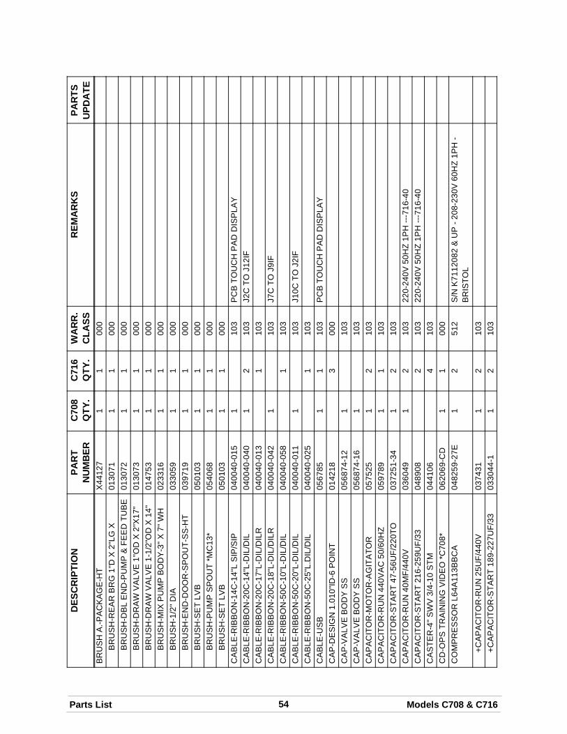
54Parts List Models C708 & C716
DES
CR
IPTI
ON
PAR
TSU
PDA
TER
EMA
RK
SW
AR
R.
CLA
SSC
716
QTY
.C
708
QTY
.PA
RT
NU
MB
ERB
RU
SH
A.-P
AC
KA
GE
-HT
X44
127
11
000
BR
US
H-R
EA
RB
RG
1"D
X2"
LGX
0130
711
100
0B
RU
SH
-DB
LE
ND
-PU
MP
&FE
ED
TUB
E01
3072
11
000
BR
US
H-D
RA
WV
ALV
E1"
OD
X2"
X17
"01
3073
11
000
BR
US
H-D
RA
WV
ALV
E1-
1/2"
OD
X14
"01
4753
11
000
BR
US
H-M
IXP
UM
PB
OD
Y-3
"X7"
WH
0233
161
100
0B
RU
SH
-1/2
"DIA
0330
591
100
0B
RU
SH
-EN
D-D
OO
R-S
PO
UT-
SS
-HT
0397
191
100
0B
RU
SH
-SE
TLV
B05
0103
11
000
BR
US
H-P
UM
PS
PO
UT
*MC
13*
0540
681
100
0B
RU
SH
-SE
TLV
B05
0103
11
000
CA
BLE
-RIB
BO
N-1
4C-1
4"L
SIP
/SIP
0400
40-0
151
103
PC
BTO
UC
HP
AD
DIS
PLA
YC
AB
LE-R
IBB
ON
-20C
-14"
L-D
IL/D
IL04
0040
-040
12
103
J2C
TOJ1
2IF
CA
BLE
-RIB
BO
N-2
0C-1
7"L-
DIL
/DIL
R04
0040
-013
110
3C
AB
LE-R
IBB
ON
-20C
-18"
L-D
IL/D
ILR
0400
40-0
421
103
J7C
TOJ9
IFC
AB
LE-R
IBB
ON
-50C
-10"
L-D
IL/D
IL04
0040
-058
110
3C
AB
LE-R
IBB
ON
-50C
-20"
L-D
IL/D
IL04
0040
-011
110
3J1
0CTO
J2IF
CA
BLE
-RIB
BO
N-5
0C-2
5"L.
DIL
/DIL
0400
40-0
251
103
CA
BLE
-US
B05
6785
11
103
PC
BTO
UC
HP
AD
DIS
PLA
YC
AP
-DE
SIG
N1.
010"
ID-6
PO
INT
0142
183
000
CA
P-V
ALV
EB
OD
YS
S05
6874
-12
110
3C
AP
-VA
LVE
BO
DY
SS
0568
74-1
61
103
CA
PA
CIT
OR
-MO
TOR
-AG
ITA
TOR
0575
251
210
3C
AP
AC
ITO
R-R
UN
440V
AC
50/6
0HZ
0597
891
110
3C
AP
AC
ITO
R-S
TAR
T47
-56U
F/22
0TO
0372
51-3
41
210
3C
AP
AC
ITO
R-R
UN
40M
F/44
0V03
6049
12
103
220-
240V
50H
Z1P
H---
716-
40C
AP
AC
ITO
R-S
TAR
T21
6-25
9UF/
3304
8908
210
322
0-24
0V50
HZ
1PH
---71
6-40
CA
STE
R-4
"SW
V3/
4-10
STM
0441
064
103
CD
-OP
STR
AIN
ING
VID
EO
*C70
8*06
2069
-CD
11
000
CO
MP
RE
SS
OR
L64A
113B
BC
A04
8259
-27E
12
512
S/N
K71
1208
2&
UP
-208
-230
V60
HZ
1PH
-B
RIS
TOL
+CA
PA
CIT
OR
-RU
N25
UF/
440V
0374
311
210
3+C
AP
AC
ITO
R-S
TAR
T18
9-22
7UF/
3303
3044
-11
210
3

55Models C708 & C716 Parts List
DES
CR
IPTI
ON
PAR
TSU
PDA
TER
EMA
RK
SW
AR
R.
CLA
SSC
716
QTY
.C
708
QTY
.PA
RT
NU
MB
ER+R
ELA
Y-S
TAR
T-C
OM
PR
ES
SO
R06
2363
12
103
+GR
OM
ME
T-C
OM
PR
ES
SO
RM
OU
NTI
NG
0374
284
800
0
+SLE
EV
E-M
OU
NTI
NG
-CO
MP
.03
9924
48
000
CO
MP
RE
SS
OR
L63A
113D
BLA
0482
59-3
31
251
2S
/NK
7112
086
&U
P-2
08-2
30V
60H
Z3P
H-
BR
ISTO
LC
OM
PR
ES
SO
RC
S20
K6E
-PFV
-238
0570
11-2
71
251
2S
/NK
7109
124
&P
RIO
R-2
08-2
30V
60H
Z1P
H-C
OP
ELA
WE
LD+C
AP
AC
ITO
R-R
UN
40M
F/44
0V03
6049
12
103
"+C
AP
AC
ITO
R-S
TAR
T18
9-22
7UF/
330V
0330
44-1
12
103
"+R
ELA
Y-S
TAR
T-C
OM
PR
ES
SO
R05
2401
-27
12
103
CO
MP
RE
SS
OR
L63A
113D
BLA
0482
59-3
31
251
2K
7112
084
&U
PC
OM
PR
ES
SO
RC
S20
K6E
-TF5
-238
0570
11-3
31
251
2S
/NK
7109
134
&P
RIO
R-2
08-2
30V
60H
Z3P
H/2
20-2
40V
50H
Z3P
H-C
OP
ELA
WE
LDC
OM
PR
ES
SO
RC
S20
K6E
-PFZ
-238
0570
11-4
01
251
2S
/NK
7066
782
&P
RIO
R-2
20-2
40V
50H
Z1P
H-C
OP
ELA
WE
LD+C
AP
AC
ITO
R-R
UN
40M
F/44
0V03
6049
110
3"
+CA
PA
CIT
OR
-STA
RT
216-
259U
F/33
0V04
8908
110
3"
+RE
LAY
-STA
RT-
CO
MP
RE
SS
OR
0519
57-4
01
103
"C
OM
PR
ES
SO
RC
S20
K6E
-TFD
-238
0570
11-5
81
251
238
0-41
5V50
HZ
3N~
(4W
IRE
)C
ON
DE
NS
ER
-AC
12LX
18H
X3.
12T-
5RW
0558
13-1
110
3LE
FTC
ON
DE
NS
ER
-AC
12LX
18H
X3.
12T-
5RW
0558
13-2
110
3R
IGH
TC
ON
DE
NS
ER
-AC
16X
163R
OW
14FP
I05
6944
110
3C
OU
PLI
NG
-DR
IVE
3/4
HE
XX
1-7/
801
2721
12
103
CO
UP
LIN
G-3
/8FS
X1/
4FS
0317
912
210
3C
OU
PLI
NG
-3/8
FSX
5/16
FS05
4654
12
103
LIN
EA
.DIS
CH
AR
GE
CO
VE
R-H
OP
PE
R*B
LAC
K*
SE
EK
ITA
.CO
VE
R-H
OP
PE
RD
EC
AL-
INS
T-C
LN-D
AY
-HT-
SS
0452
731
100
0D
EC
AL-
INS
T-C
LN-H
T-S
S04
5276
11
000
DE
CA
L-TR
OU
BLE
SH
OO
T03
8374
11
000
DE
FLE
CTO
R-B
LOW
ER
-EX
HA
US
T05
9929
110
3D
IAG
RA
M-W
IRIN
G*C
708/
C70
9*05
7010
-27
100
020
8-23
0V60
HZ
1PH
DIA
GR
AM
-WIR
ING
*C70
8/C
709*
0570
10-3
31
000
208-
230V
60H
Z3P
H
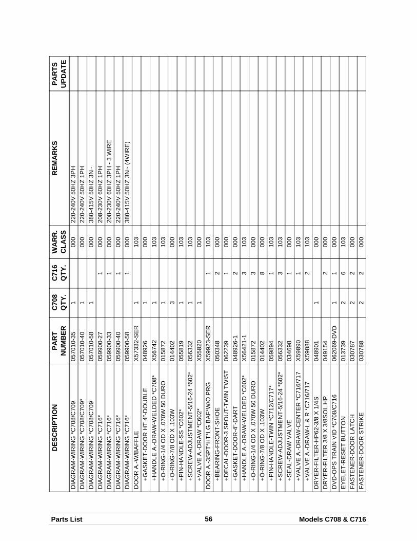
56Parts List Models C708 & C716
DES
CR
IPTI
ON
PAR
TSU
PDA
TER
EMA
RK
SW
AR
R.
CLA
SSC
716
QTY
.C
708
QTY
.PA
RT
NU
MB
ERD
IAG
RA
M-W
IRIN
G*C
708/
C70
905
7010
-35
100
022
0-24
0V50
HZ
3PH
DIA
GR
AM
-WIR
ING
*C70
8/C
709*
0570
10-4
01
000
220-
240V
50H
Z1P
HD
IAG
RA
M-W
IRIN
G*C
708/
C70
905
7010
-58
100
038
0-41
5V50
HZ
3N~
DIA
GR
AM
-WIR
ING
*C71
6*05
9900
-27
100
020
8-23
0V60
HZ
1PH
DIA
GR
AM
-WIR
ING
*C71
6*05
9900
-33
100
020
8-23
0V60
HZ
3PH
-3W
IRE
DIA
GR
AM
-WIR
ING
*C71
6*05
9900
-40
100
022
0-24
0V50
HZ
1PH
DIA
GR
AM
-WIR
ING
*C71
6*05
9900
-58
100
038
0-41
5V50
HZ
3N~
(4W
IRE
)D
OO
RA
.-W/B
AFF
LEX
5733
2-S
ER
110
3+G
AS
KE
T-D
OO
RH
T4"
-DO
UB
LE04
8926
100
0+H
AN
DLE
A.-D
RA
W-W
ELD
ED
*C70
8*X
5674
21
103
+O-R
ING
-1/4
OD
X.0
70W
50D
UR
O01
5872
110
3+O
-RIN
G-7
/8O
DX
.103
W01
4402
300
0+P
IN-H
AN
DLE
-SS
*C60
2*05
5819
110
3+S
CR
EW
-AD
JUS
TME
NT-
5/16
-24
*602
*05
6332
110
3+V
ALV
EA
.-DR
AW
*C60
2*X
5582
01
000
DO
OR
A.-3
SP
T*H
T*LG
BA
F*W
/OP
RG
X59
923-
SE
R1
103
+BE
AR
ING
-FR
ON
T-S
HO
E05
0348
200
0+D
EC
AL-
DO
OR
-3S
PO
UT-
TWIN
TWIS
T06
2239
100
0+G
AS
KE
T-D
OO
R-4
"-D
AR
T04
8926
-12
000
+HA
ND
LEA
.-DR
AW
-WE
LDE
D*C
602*
X56
421-
13
103
+O-R
ING
-1/4
OD
X.0
70W
50D
UR
O01
5872
300
0+O
-RIN
G-7
/8O
DX
.103
W01
4402
800
0+P
IN-H
AN
DLE
-TW
IN*C
712/
C71
7*05
9894
110
3+S
CR
EW
-AD
JUS
TME
NT-
5/16
-24
*602
*05
6332
310
3+S
EA
L-D
RA
WV
ALV
E03
4698
100
0+V
ALV
EA
.-DR
AW
-CE
NTE
R*C
716/
717
X59
890
110
3+V
ALV
EA
.-DR
AW
-L&
R*C
716/
717
X59
888
210
3D
RY
ER
-FIL
TER
-HP
62-3
/8X
1/4S
0489
011
000
DR
YE
R-F
ILTE
R3/
8X
3/8S
OL
HP
0491
542
000
DV
D-O
PS
TRA
INV
ID*C
708/
C71
606
2069
-DV
D1
100
0E
YE
LET-
RE
SE
TB
UTT
ON
0137
392
610
3FA
STE
NE
R-D
OO
RLA
TCH
0307
872
200
0FA
STE
NE
R-D
OO
RS
TRIK
E03
0788
22
000
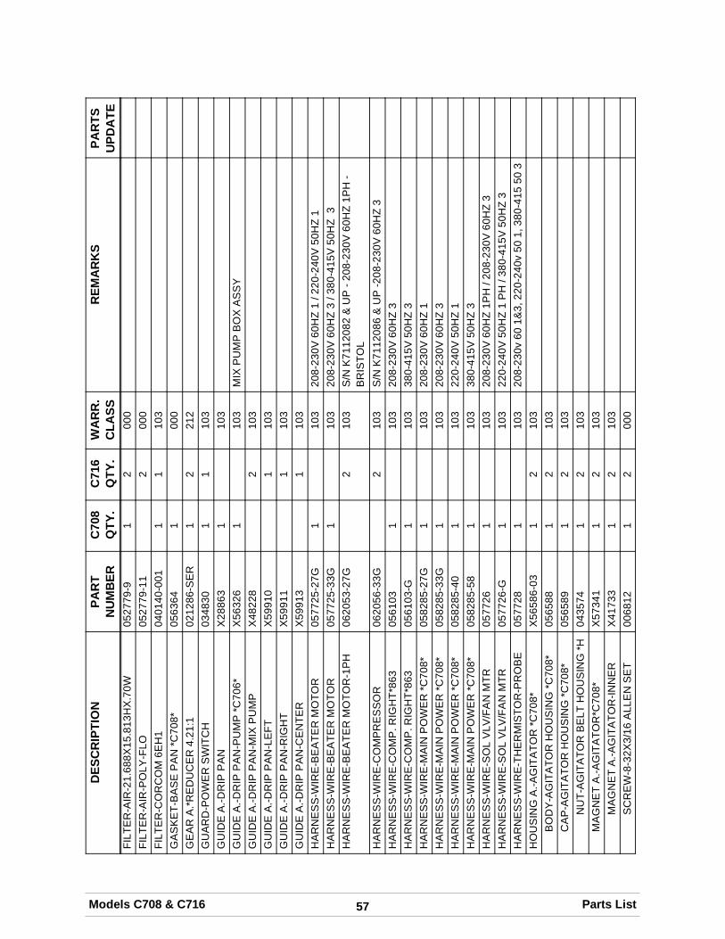
57Models C708 & C716 Parts List
DES
CR
IPTI
ON
PAR
TSU
PDA
TER
EMA
RK
SW
AR
R.
CLA
SSC
716
QTY
.C
708
QTY
.PA
RT
NU
MB
ERFI
LTE
R-A
IR-2
1.68
8X15
.813
HX
.70W
0527
79-9
12
000
FILT
ER
-AIR
-PO
LY-F
LO05
2779
-11
200
0FI
LTE
R-C
OR
CO
M6E
H1
0401
40-0
011
110
3G
AS
KE
T-B
AS
EP
AN
*C70
8*05
6364
100
0G
EA
RA
.*RE
DU
CE
R4.
21:1
0212
86-S
ER
12
212
GU
AR
D-P
OW
ER
SW
ITC
H03
4830
11
103
GU
IDE
A.-D
RIP
PA
NX
2886
31
103
GU
IDE
A.-D
RIP
PA
N-P
UM
P*C
706*
X56
326
110
3M
IXP
UM
PB
OX
AS
SY
GU
IDE
A.-D
RIP
PA
N-M
IXP
UM
PX
4822
82
103
GU
IDE
A.-D
RIP
PA
N-L
EFT
X59
910
110
3G
UID
EA
.-DR
IPP
AN
-RIG
HT
X59
911
110
3G
UID
EA
.-DR
IPP
AN
-CE
NTE
RX
5991
31
103
HA
RN
ES
S-W
IRE
-BE
ATE
RM
OTO
R05
7725
-27G
110
320
8-23
0V60
HZ
1/2
20-2
40V
50H
Z1
HA
RN
ES
S-W
IRE
-BE
ATE
RM
OTO
R05
7725
-33G
110
320
8-23
0V60
HZ
3/3
80-4
15V
50H
Z3
HA
RN
ES
S-W
IRE
-BE
ATE
RM
OTO
R-1
PH
0620
53-2
7G2
103
S/N
K71
1208
2&
UP
-208
-230
V60
HZ
1PH
-B
RIS
TOL
HA
RN
ES
S-W
IRE
-CO
MP
RE
SS
OR
0620
56-3
3G2
103
S/N
K71
1208
6&
UP
-208
-230
V60
HZ
3H
AR
NE
SS
-WIR
E-C
OM
P.R
IGH
T*86
305
6103
110
320
8-23
0V60
HZ
3H
AR
NE
SS
-WIR
E-C
OM
P.R
IGH
T*86
305
6103
-G1
103
380-
415V
50H
Z3
HA
RN
ES
S-W
IRE
-MA
INP
OW
ER
*C70
8*05
8285
-27G
110
320
8-23
0V60
HZ
1H
AR
NE
SS
-WIR
E-M
AIN
PO
WE
R*C
708*
0582
85-3
3G1
103
208-
230V
60H
Z3
HA
RN
ES
S-W
IRE
-MA
INP
OW
ER
*C70
8*05
8285
-40
110
322
0-24
0V50
HZ
1H
AR
NE
SS
-WIR
E-M
AIN
PO
WE
R*C
708*
0582
85-5
81
103
380-
415V
50H
Z3
HA
RN
ES
S-W
IRE
-SO
LV
LV/F
AN
MTR
0577
261
103
208-
230V
60H
Z1P
H/2
08-2
30V
60H
Z3
HA
RN
ES
S-W
IRE
-SO
LV
LV/F
AN
MTR
0577
26-G
110
322
0-24
0V50
HZ
1P
H/3
80-4
15V
50H
Z3
HA
RN
ES
S-W
IRE
-TH
ER
MIS
TOR
-PR
OB
E05
7728
110
320
8-23
0v60
1&3,
220-
240v
501,
380-
415
503
HO
US
ING
A.-A
GIT
ATO
R*C
708*
X56
586-
031
210
3B
OD
Y-A
GIT
ATO
RH
OU
SIN
G*C
708*
0565
881
210
3C
AP
-AG
ITA
TOR
HO
US
ING
*C70
8*05
6589
12
103
NU
T-A
GIT
ATO
RB
ELT
HO
US
ING
*H04
3574
12
103
MA
GN
ET
A.-A
GIT
ATO
R*C
708*
X57
341
12
103
MA
GN
ET
A.-A
GIT
ATO
R-IN
NE
RX
4173
31
210
3S
CR
EW
-8-3
2X3/
16A
LLE
NS
ET
0068
121
200
0
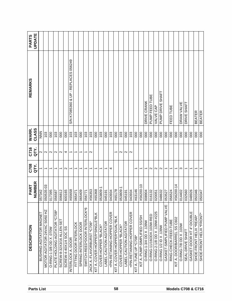
58Parts List Models C708 & C716
DES
CR
IPTI
ON
PAR
TSU
PDA
TER
EMA
RK
SW
AR
R.
CLA
SSC
716
QTY
.C
708
QTY
.PA
RT
NU
MB
ERB
US
HIN
G-A
GIT
ATO
RM
AG
NE
T05
7342
12
NN
NM
OTO
R-A
GIT
ATO
R-2
4VA
C50
/60
HZ
0505
35-0
31
210
3O
-RIN
G-1
-3/8
OD
X.0
70W
0173
951
200
0P
LATE
-HO
LDIN
G-A
GIT
ATO
R*C
708*
0565
871
210
3S
CR
EW
-8-3
2X3/
16A
LLE
NS
ET
0068
121
200
0S
CR
EW
-4-4
0X1/
4S
OC
SS
6001
652
400
0IN
TER
LOC
KA
.-DO
OR
X65
658
11
103
S/N
K70
8536
0&
UP
-RE
PLA
CE
S05
6249
FITT
ING
DO
OR
INTE
RLO
CK
0654
711
110
3S
PR
ING
-INTE
RLO
CK
DO
OR
0654
091
100
0S
WIT
CH
-RE
ED
*DO
OR
INTE
RLO
CK
*605
6771
11
103
JAC
KA
.-FLA
VO
RB
UR
ST
*C70
6*X
5635
31
210
3K
ITA
.-CO
VE
R-H
OP
PE
R*S
ING
LE*B
LKX
6536
81
000
CO
VE
R-H
OP
PE
R*B
LAC
K*
0538
09-1
110
3LA
BE
L-C
AU
TIO
N-A
GIT
ATO
R04
5191
100
0+P
IN-R
ETA
ININ
G-H
OP
PE
RC
OV
ER
0439
344
103
KIT
A.-C
OV
ER
-HO
PP
ER
*DU
AL*
BLK
X65
178
100
0C
OV
ER
-HO
PP
ER
*BLA
CK
*05
3809
-12
103
LAB
EL-
CA
UTI
ON
-AG
ITA
TOR
0451
912
000
+PIN
-RE
TAIN
ING
-HO
PP
ER
CO
VE
R04
3934
210
3K
ITA
.-TU
NE
UP
*C70
8*X
6314
61
000
KIT
A.-P
UM
P-S
IMP
LIFI
ED
SS
/SH
X56
200-
101
000
O-R
ING
-1-3
/4O
DX
.139
W00
8904
100
0D
RIV
EC
RA
NK
O-R
ING
-11/
16O
DX
.103
W-R
ED
0161
322
000
PU
MP
FEE
DTU
BE
O-R
ING
-2-1
/8O
DX
.139
W-#
225
0200
512
000
VA
LVE
CA
PO
-RIN
G1/
2ID
X.1
39W
0486
322
000
PU
MP
DR
IVE
SH
AFT
GA
SK
ET-
SIM
PLI
FIE
DP
UM
PV
ALV
E05
3527
100
0R
ING
-CH
EC
K-F
EE
D-T
UB
E05
6524
100
0FE
ED
TUB
EK
ITA
.-DO
OR
/BA
RR
EL
SS
C60
2X
5620
0-14
100
0O
-RIN
G-7
/8O
DX
.103
W01
4402
300
0D
RA
WV
ALV
ES
EA
L-D
RIV
ES
HA
FT03
2560
100
0D
RIV
ES
HA
FTG
AS
KE
T-D
OO
RH
T4"
-DO
UB
LE04
8926
100
0S
HO
E-F
RO
NT
HE
LIX
*RE
AR
*05
0346
100
0B
EA
TER
SH
OE
-FR
ON
TH
ELI
X*F
RO
NT*
0503
471
000
BE
ATE
R
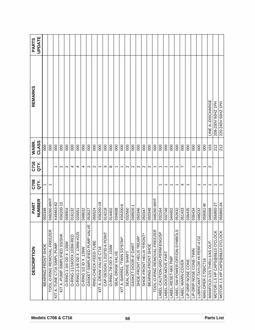
59Models C708 & C716 Parts List
DES
CR
IPTI
ON
PAR
TSU
PDA
TER
EMA
RK
SW
AR
R.
CLA
SSC
716
QTY
.C
708
QTY
.PA
RT
NU
MB
ERB
EA
RIN
G-F
RO
NT-
SH
OE
0503
481
000
TOO
L-O
-RIN
GR
EM
OV
AL-
FRE
EZE
R04
8260
-WH
T1
000
KIT
A.-T
UN
EC
716
SIM
PL
PU
MP
X49
463-
821
000
KIT
A.-P
UM
P-S
IMP
LIFI
ED
SS
/SH
KX
5620
0-10
200
0O
-RIN
G-1
-3/4
OD
X.1
39W
0089
042
000
O-R
ING
-11/
16O
DX
.103
W-R
ED
0161
324
000
O-R
ING
-2-1
/8O
DX
.139
W-#
225
0200
514
000
O-R
ING
1/2
IDX
.139
W04
8632
400
0G
AS
KE
T-S
IMP
LIFI
ED
PU
MP
VA
LVE
0535
272
000
RIN
G-C
HE
CK
-FE
ED
-TU
BE
0565
242
000
KIT
A.-D
RA
WV
ALV
EC
716
X56
200-
181
000
CA
P-D
ES
IGN
1.01
0"ID
-6P
OIN
T01
4218
300
0O
-RIN
G-7
/8O
DX
.103
W01
4402
800
0S
EA
L-D
RA
WV
ALV
E03
4698
100
0K
ITA
.-BA
RR
EL
*TW
INS
S*8
784*
X56
200-
61
000
SE
AL-
DR
IVE
SH
AFT
0325
602
000
GA
SK
ET-
DO
OR
-4"-
DA
RT
0489
26-1
200
0S
HO
E-F
RO
NT
HE
LIX
*RE
AR
*05
0346
200
0S
HO
E-F
RO
NT
HE
LIX
*FR
ON
T*05
0347
200
0B
EA
RIN
G-F
RO
NT-
SH
OE
0503
482
000
TOO
L-O
-RIN
GR
EM
OV
AL-
FRE
EZE
R04
8260
-WH
T1
000
LAB
EL-
CA
UTI
ON
-GR
D-P
ER
M-E
NG
/SP
0321
641
100
0LA
BE
L-D
OO
R-M
OV
EP
AR
T03
2749
11
000
LAB
EL-
RE
SE
T-M
IXP
MP
0444
521
100
0LA
BE
L-S
W-P
OW
ER
-OFF
/ON
-SY
MB
OLS
0526
321
100
0LA
BE
L-W
AR
N-C
OV
ER
0514
334
700
0LI
P-D
RIP
-NO
SE
CO
NE
0364
351
000
LIP
-DR
IP-N
OS
EC
ON
E-T
WIN
0364
341
000
LUB
RIC
AN
T-TA
YLO
RH
IPE
RF-
4O
Z04
8232
11
000
MA
N-O
PE
RC
708/
C71
605
9061
-M1
100
0M
AN
IFO
LD-1
/2S
THR
U-1
/4S
OU
T-04
6688
12
103
LIN
EA
.-DIS
CH
AR
GE
MO
TOR
-1.5
HP
CA
PS
@8&
10O
'CLO
CK
0568
65-2
71
212
208-
230V
60H
Z1P
HM
OTO
R-1
.5H
PC
AP
S@
8&10
O'C
LOC
K05
6865
-34
121
222
0-24
0V50
HZ
1PH
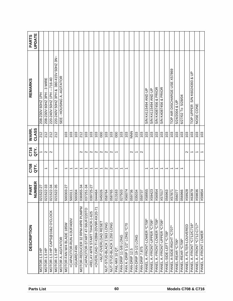
60Parts List Models C708 & C716
DES
CR
IPTI
ON
PAR
TSU
PDA
TER
EMA
RK
SW
AR
R.
CLA
SSC
716
QTY
.C
708
QTY
.PA
RT
NU
MB
ERM
OTO
R-1
.5H
P02
1522
-27
121
220
8-23
0V60
HZ
1PH
MO
TOR
-1.5
HP
0215
22-3
31
221
220
8-23
0V60
HZ
3PH
-3W
IRE
MO
TOR
-1.5
HP
CA
PS
@10
&2
O'C
LOC
K02
1522
-34
221
222
0-24
0V50
HZ
1PH
---71
6-40
MO
TOR
-1.5
HP
0215
22-3
51
212
220-
240V
50H
Z3P
H&
380-
415V
50H
Z3N
~M
OTO
RA
.-AG
ITA
TOR
SE
E-H
OU
SIN
GA
.-AG
ITA
TOR
MO
TOR
-FA
NW
/4B
LAD
E18
5W50
0303
-27
110
3+C
AP
AC
ITO
R-R
UN
4.0U
F/40
0V50
0311
110
3+G
UA
RD
-FA
N50
0304
110
3M
OTO
R-R
ED
UC
ER
32R
PM
-HP
RP
UM
PM
0369
55-3
41
221
2+C
AP
AC
ITO
R-S
TAR
T47
-56U
F/22
0TO
0372
51-3
41
210
3+R
ELA
Y-M
TRS
TAR
TTI
#4C
R-1
-625
0397
25-2
71
210
3+O
VE
RLO
AD
-TI#
2BM
-20V
9R-K
K20
-71
0444
641
210
3+N
UT-
OV
ER
LOA
DR
ES
ET
0450
261
200
0N
UT-
STU
D-B
LAC
K2.
563
LON
G05
8764
22
103
NU
T-S
TUD
-BLA
CK
3.25
0LO
NG
0587
652
210
3P
AIL
-MIX
10Q
T.01
3163
11
000
PA
N-D
RIP
11-5
/8LO
NG
0275
031
103
PA
NA
.-DR
IP5
1/2"
LON
G*C
70X
5607
41
103
PA
N-D
RIP
12.5
0597
362
NN
NP
AN
-DR
IP19
-1/2
LON
G03
5034
110
3P
AN
-DR
IP7.
875
0597
372
103
PA
NE
LA
.-FR
ON
T-LO
WE
R*C
708*
X58
955
110
3S
/NK
4115
494
AN
DU
PP
AN
EL
A.-F
RO
NT-
UP
PE
R*C
708*
X59
423
110
3S
/NK
4115
494
AN
DU
PP
AN
EL
A.-F
RO
NT-
LOW
ER
*C70
8*X
5695
41
103
S/N
K40
8745
6&
PR
IOR
PA
NE
LA
.-FR
ON
T-U
PP
ER
*C70
8*X
5701
71
103
S/N
K40
8745
6&
PR
IOR
PA
NE
L-S
IDE
-LE
FT*C
708*
0569
631
103
PA
NE
LA
-SID
E-R
IGH
T*C
707*
X57
871
110
3TO
PA
IRD
ISC
HA
RG
EU
SE
X57
869
PA
NE
L-R
EA
R*C
706*
0560
771
103
5/24
/200
4&
UP
PA
NE
L-R
EA
R*C
708*
0569
661
103
6/27
/02
To5/
28/0
4P
AN
EL
A.-F
ILTE
R-L
OU
VE
RE
DX
5992
82
103
PA
NE
LA
.-FR
ON
T*C
712/
C71
6*X
6387
91
103
TOP
UP
PE
RS
/NK
6024
393
&U
PP
AN
EL
A.-F
RO
NT
*C71
2-C
717*
X59
836
110
3N
OS
EC
ON
EP
AN
EL
A.-F
RO
NT
LOW
ER
X59
854
110
3
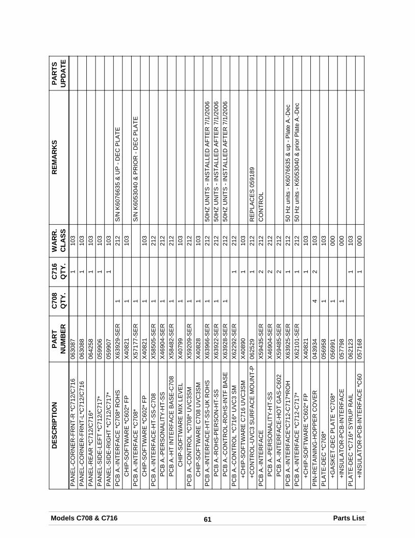
61Models C708 & C716 Parts List
DES
CR
IPTI
ON
PAR
TSU
PDA
TER
EMA
RK
SW
AR
R.
CLA
SSC
716
QTY
.C
708
QTY
.PA
RT
NU
MB
ERP
AN
EL-
CO
RN
ER
-FR
NT-
R*C
712/
C71
606
3087
110
3P
AN
EL-
CO
RN
ER
-FR
NT-
L*C
712/
C71
606
3088
110
3P
AN
EL-
RE
AR
*C71
2/C
716*
0642
581
103
PA
NE
L-S
IDE
-LE
FT*C
712/
C71
7*05
9906
110
3P
AN
EL-
SID
E-R
IGH
T*C
712/
C71
7*05
9907
110
3P
CB
A.-I
NTE
RFA
CE
*C70
8*R
OH
SX
6392
9-S
ER
121
2S
/NK
6076
635
&U
P-D
EC
PLA
TEC
HIP
-SO
FTW
AR
E*C
602*
FPX
4082
11
103
PC
BA
.-IN
TER
FAC
E*C
708*
X57
177-
SE
R1
S/N
K60
5304
0&
PR
IOR
-DE
CP
LATE
CH
IP-S
OFT
WA
RE
*C60
2*FP
X40
821
110
3P
CB
A.-I
NTE
RFA
CE
-HT-
SS
-C70
8X
5850
5-S
ER
121
2P
CB
A.-P
ER
SO
NA
LITY
-HT-
SS
X46
904-
SE
R1
212
PC
BA
.-HT
INTE
RFA
CE
BA
SE
-C70
8X
5848
2-S
ER
121
2C
HIP
-SO
FTW
AR
EM
IXLE
VE
LX
4079
91
103
PC
BA
.-CO
NTR
OL
*C70
8*U
VC
3SM
X59
209-
SE
R1
212
CH
IP-S
OFT
WA
RE
C70
8U
VC
3SM
X40
828
110
3P
CB
A.-I
NTE
RFA
CE
-HT-
SS
-UK
RO
HS
X63
966-
SE
R1
212
50H
ZU
NIT
S-I
NS
TALL
ED
AFT
ER
7/1/
2006
PC
BA
.-RO
HS
-PE
RS
ON
-HT-
SS
X63
922-
SE
R1
212
50H
ZU
NIT
S-I
NS
TALL
ED
AFT
ER
7/1/
2006
PC
BA
.-CO
NTR
OL-
RO
HS
-INTF
BA
SE
X63
928-
SE
R1
212
50H
ZU
NIT
S-I
NS
TALL
ED
AFT
ER
7/1/
2006
PC
BA
.-CO
NTR
OL
*C71
6*U
VC
3S
MX
6229
2-S
ER
121
2+C
HIP
-SO
FTW
AR
EC
716
UV
C3S
MX
4089
01
103
+CO
NTR
OL-
UV
C3
SU
RFA
CE
MO
UN
T-P
0625
291
212
RE
PLA
CE
S05
9189
PC
BA
.-IN
TER
FAC
EX
5943
5-S
ER
221
2C
ON
TRO
LP
CB
A.-P
ER
SO
NA
LITY
-HT-
SS
X46
904-
SE
R2
212
PC
BA
.-IN
TER
FAC
E-H
OT
GA
S-C
602
X59
485-
SE
R2
212
PC
BA
.-IN
TER
FAC
E*C
712-
C71
7*R
OH
X63
925-
SE
R1
212
50H
zun
its-K
6076
635
&up
-Pla
teA
.-Dec
PC
BA
.-IN
TER
FAC
E*C
712-
C71
7*X
6210
1-S
ER
121
250
Hz
units
-K60
5304
0&
prio
rPla
teA
.-Dec
+CH
IP-S
OFT
WA
RE
*C60
2*FP
X40
821
110
3P
IN-R
ETA
ININ
G-H
OP
PE
RC
OV
ER
0439
344
210
3P
LATE
-DE
C*C
708*
0569
581
103
+GA
SK
ET-
DE
CP
LATE
*C70
8*05
6991
100
0+I
NS
ULA
TOR
-PC
B-IN
TER
FAC
E05
7798
100
0P
LATE
-DE
C*C
716*
SY
RU
PR
AIL
0621
231
103
+IN
SU
LATO
R-P
CB
-INTE
RFA
CE
*C60
0571
681
000
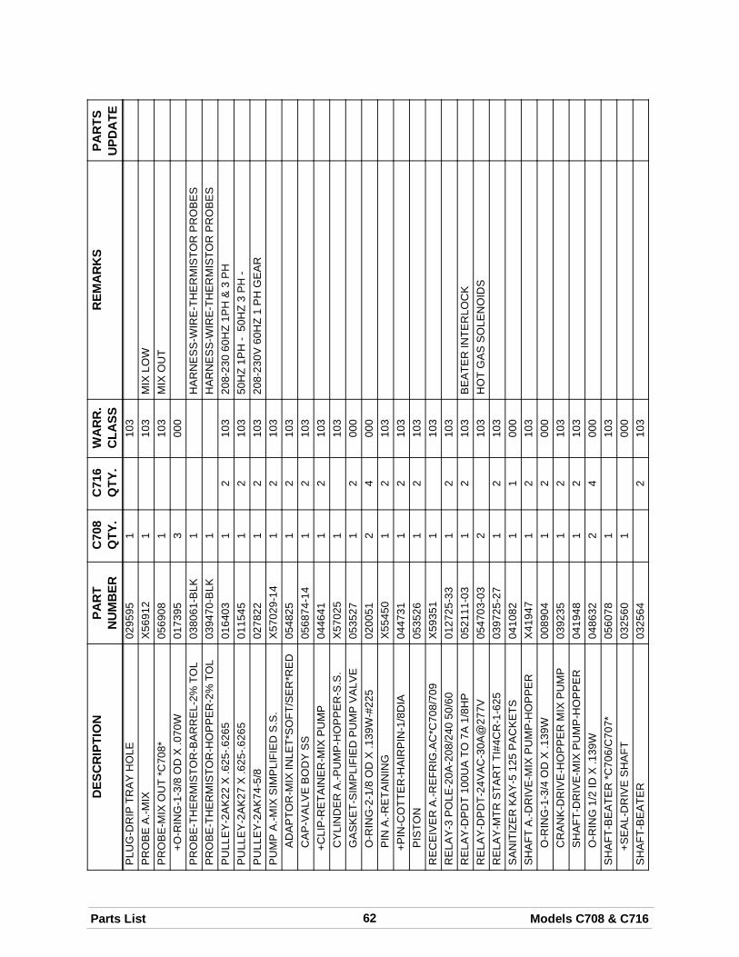
62Parts List Models C708 & C716
DES
CR
IPTI
ON
PAR
TSU
PDA
TER
EMA
RK
SW
AR
R.
CLA
SSC
716
QTY
.C
708
QTY
.PA
RT
NU
MB
ERP
LUG
-DR
IPTR
AY
HO
LE02
9595
110
3P
RO
BE
A.-M
IXX
5691
21
103
MIX
LOW
PR
OB
E-M
IXO
UT
*C70
8*05
6908
110
3M
IXO
UT
+O-R
ING
-1-3
/8O
DX
.070
W01
7395
300
0P
RO
BE
-TH
ER
MIS
TOR
-BA
RR
EL-
2%TO
L03
8061
-BLK
1H
AR
NE
SS
-WIR
E-T
HE
RM
ISTO
RP
RO
BE
SP
RO
BE
-TH
ER
MIS
TOR
-HO
PP
ER
-2%
TOL
0394
70-B
LK1
HA
RN
ES
S-W
IRE
-TH
ER
MIS
TOR
PR
OB
ES
PU
LLE
Y-2
AK
22X
.625
-.626
501
6403
12
103
208-
230
60H
Z1P
H&
3P
HP
ULL
EY
-2A
K27
X.6
25-.6
265
0115
451
210
350
HZ
1PH
-50
HZ
3P
H-
PU
LLE
Y-2
AK
74-5
/802
7822
12
103
208-
230V
60H
Z1
PH
GE
AR
PU
MP
A.-M
IXS
IMP
LIFI
ED
S.S
.X
5702
9-14
12
103
AD
AP
TOR
-MIX
INLE
T*S
OFT
/SE
R*R
ED
0548
251
210
3C
AP
-VA
LVE
BO
DY
SS
0568
74-1
41
210
3+C
LIP
-RE
TAIN
ER
-MIX
PU
MP
0446
411
210
3C
YLI
ND
ER
A.-P
UM
P-H
OP
PE
R-S
.S.
X57
025
110
3G
AS
KE
T-S
IMP
LIFI
ED
PU
MP
VA
LVE
0535
271
200
0O
-RIN
G-2
-1/8
OD
X.1
39W
-#22
502
0051
24
000
PIN
A.-R
ETA
ININ
GX
5545
01
210
3+P
IN-C
OTT
ER
-HA
IRP
IN-1
/8D
IA04
4731
12
103
PIS
TON
0535
261
210
3R
EC
EIV
ER
A.-R
EFR
IG.A
C*C
708/
709
X59
351
110
3R
ELA
Y-3
PO
LE-2
0A-2
08/2
4050
/60
0127
25-3
31
210
3R
ELA
Y-D
PD
T10
0UA
TO7A
1/8H
P05
2111
-03
12
103
BE
ATE
RIN
TER
LOC
KR
ELA
Y-D
PD
T-24
VA
C-3
0A@
277V
0547
03-0
32
103
HO
TG
AS
SO
LEN
OID
SR
ELA
Y-M
TRS
TAR
TTI
#4C
R-1
-625
0397
25-2
71
210
3S
AN
ITIZ
ER
KA
Y-5
125
PA
CK
ETS
0410
821
100
0S
HA
FTA
.-DR
IVE
-MIX
PU
MP
-HO
PP
ER
X41
947
12
103
O-R
ING
-1-3
/4O
DX
.139
W00
8904
12
000
CR
AN
K-D
RIV
E-H
OP
PE
RM
IXP
UM
P03
9235
12
103
SH
AFT
-DR
IVE
-MIX
PU
MP
-HO
PP
ER
0419
481
210
3O
-RIN
G1/
2ID
X.1
39W
0486
322
400
0S
HA
FT-B
EA
TER
*C70
6/C
707*
0560
781
103
+SE
AL-
DR
IVE
SH
AFT
0325
601
000
SH
AFT
-BE
ATE
R03
2564
210
3
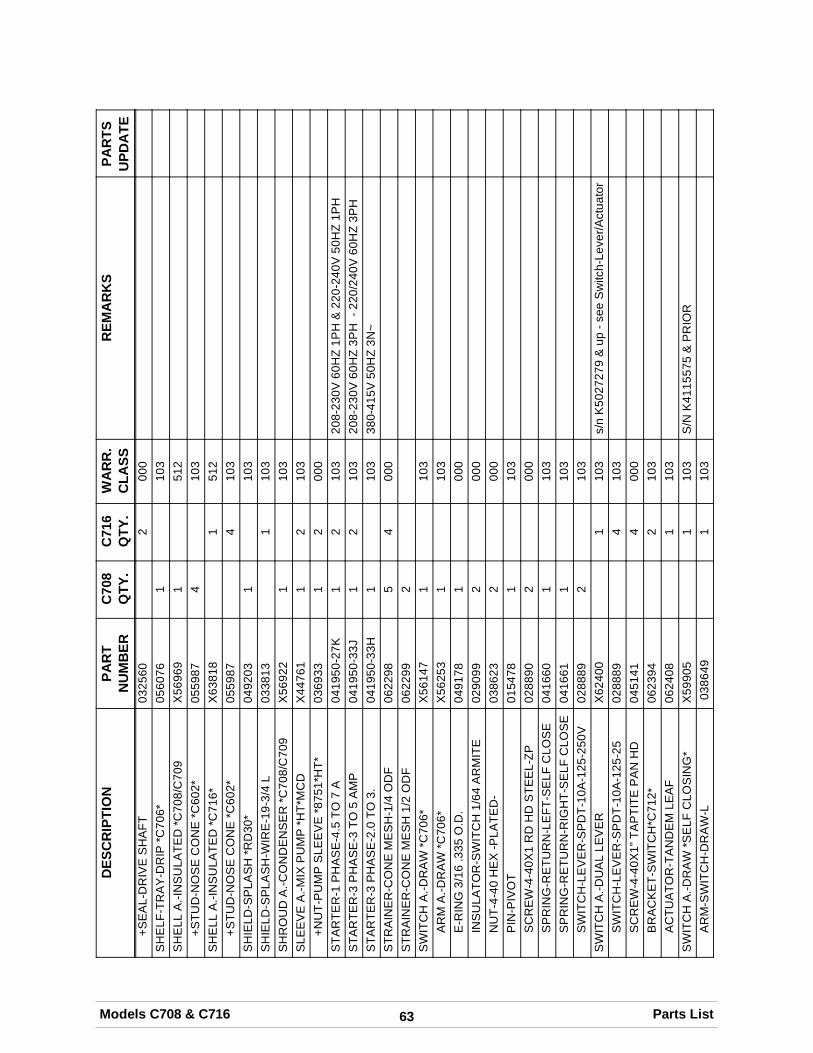
63Models C708 & C716 Parts List
DES
CR
IPTI
ON
PAR
TSU
PDA
TER
EMA
RK
SW
AR
R.
CLA
SSC
716
QTY
.C
708
QTY
.PA
RT
NU
MB
ER+S
EA
L-D
RIV
ES
HA
FT03
2560
200
0S
HE
LF-T
RA
Y-D
RIP
*C70
6*05
6076
110
3S
HE
LLA
.-IN
SU
LATE
D*C
708/
C70
9X
5696
91
512
+STU
D-N
OS
EC
ON
E*C
602*
0559
874
103
SH
ELL
A.-I
NS
ULA
TED
*C71
6*X
6381
81
512
+STU
D-N
OS
EC
ON
E*C
602*
0559
874
103
SH
IELD
-SP
LAS
H*R
D30
*04
9203
110
3S
HIE
LD-S
PLA
SH
-WIR
E-1
9-3/
4L
0338
131
103
SH
RO
UD
A.-C
ON
DE
NS
ER
*C70
8/C
709
X56
922
110
3S
LEE
VE
A.-M
IXP
UM
P*H
T*M
CD
X44
761
12
103
+NU
T-P
UM
PS
LEE
VE
*875
1*H
T*03
6933
12
000
STA
RTE
R-1
PH
AS
E-4
.5TO
7A
0419
50-2
7K1
210
320
8-23
0V60
HZ
1PH
&22
0-24
0V50
HZ
1PH
STA
RTE
R-3
PH
AS
E-3
TO5
AM
P04
1950
-33J
12
103
208-
230V
60H
Z3P
H-2
20/2
40V
60H
Z3P
HS
TAR
TER
-3P
HA
SE
-2.0
TO3.
0419
50-3
3H1
103
380-
415V
50H
Z3N
~S
TRA
INE
R-C
ON
EM
ES
H-1
/4O
DF
0622
985
400
0S
TRA
INE
R-C
ON
EM
ES
H1/
2O
DF
0622
992
SW
ITC
HA
.-DR
AW
*C70
6*X
5614
71
103
AR
MA
.-DR
AW
*C70
6*X
5625
31
103
E-R
ING
3/16
.335
O.D
.04
9178
100
0IN
SU
LATO
R-S
WIT
CH
1/64
AR
MIT
E02
9099
200
0N
UT-
4-40
HE
X-P
LATE
D-
0386
232
000
PIN
-PIV
OT
0154
781
103
SC
RE
W-4
-40X
1R
DH
DS
TEE
L-ZP
0288
902
000
SP
RIN
G-R
ETU
RN
-LE
FT-S
ELF
CLO
SE
0416
601
103
SP
RIN
G-R
ETU
RN
-RIG
HT-
SE
LFC
LOS
E04
1661
110
3S
WIT
CH
-LE
VE
R-S
PD
T-10
A-1
25-2
50V
0288
892
103
SW
ITC
HA
.-DU
AL
LEV
ER
X62
400
110
3s/
nK
5027
279
&up
-see
Sw
itch-
Leve
r/Act
uato
rS
WIT
CH
-LE
VE
R-S
PD
T-10
A-1
25-2
502
8889
410
3S
CR
EW
-4-4
0X1"
TAP
TITE
PA
NH
D04
5141
400
0B
RA
CK
ET-
SW
ITC
H*C
712*
0623
942
103
AC
TUA
TOR
-TA
ND
EM
LEA
F06
2408
110
3S
WIT
CH
A.-D
RA
W*S
ELF
CLO
SIN
G*
X59
905
110
3S
/NK
4115
575
&P
RIO
RA
RM
-SW
ITC
H-D
RA
W-L
0386
491
103
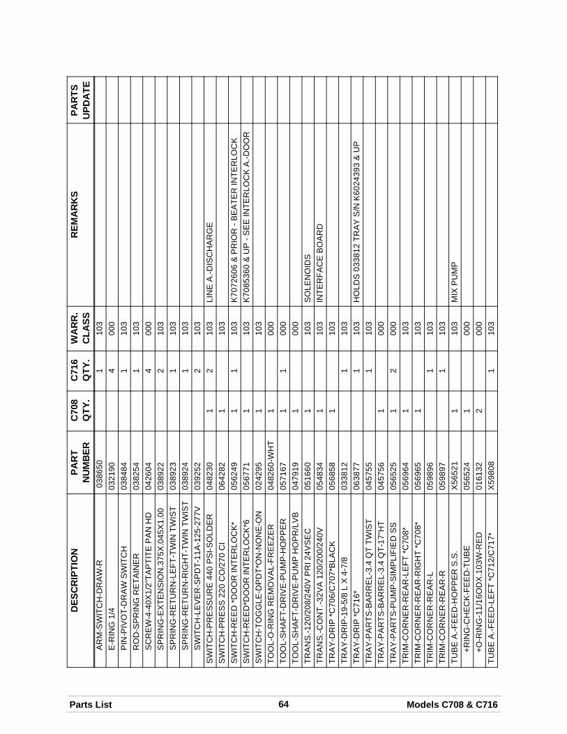
64Parts List Models C708 & C716
DES
CR
IPTI
ON
PAR
TSU
PDA
TER
EMA
RK
SW
AR
R.
CLA
SSC
716
QTY
.C
708
QTY
.PA
RT
NU
MB
ERA
RM
-SW
ITC
H-D
RA
W-R
0386
501
103
E-R
ING
1/4
0321
904
000
PIN
-PIV
OT-
DR
AW
SW
ITC
H03
8484
110
3R
OD
-SP
RIN
GR
ETA
INE
R03
8254
110
3S
CR
EW
-4-4
0X1/
2"TA
PTI
TEP
AN
HD
0426
044
000
SP
RIN
G-E
XTE
NS
ION
.375
X.0
45X
1.00
0389
222
103
SP
RIN
G-R
ETU
RN
-LE
FT-T
WIN
TWIS
T03
8923
110
3S
PR
ING
-RE
TUR
N-R
IGH
T-TW
INTW
IST
0389
241
103
SW
ITC
H-L
EV
ER
-SP
DT-
11A
-125
-277
V03
9252
210
3S
WIT
CH
-PR
ES
SU
RE
440
PS
I-SO
LDE
R04
8230
12
103
LIN
EA
.-DIS
CH
AR
GE
SW
ITC
H-P
RE
SS
220
CO
/270
CI
0642
821
103
SW
ITC
H-R
EE
D*D
OO
RIN
TER
LOC
K*
0562
491
110
3K
7072
606
&P
RIO
R-B
EA
TER
INTE
RLO
CK
SW
ITC
H-R
EE
D*D
OO
RIN
TER
LOC
K*6
0567
711
103
K70
8536
0&
UP
-SE
EIN
TER
LOC
KA
.-DO
OR
SW
ITC
H-T
OG
GLE
-DP
DT*
ON
-NO
NE
-ON
0242
951
103
TOO
L-O
-RIN
GR
EM
OV
AL-
FRE
EZE
R04
8260
-WH
T1
000
TOO
L-S
HA
FT-D
RIV
E-P
UM
P-H
OP
PE
R05
7167
11
000
TOO
L-S
HA
FT-D
RIV
E-P
UM
PH
OP
R/L
VB
0479
191
000
TRA
NS
.-120
/208
/240
VP
RI2
4VS
EC
0516
601
103
SO
LEN
OID
STR
AN
S.-C
ON
T.-3
2VA
120/
200/
240V
0548
341
103
INTE
RFA
CE
BO
AR
DTR
AY
-DR
IP*C
706/
C70
7*B
LAC
K05
6858
110
3TR
AY
-DR
IP-1
9-5/
8L
X4-
7/8
0338
121
103
TRA
Y-D
RIP
*C71
6*06
3877
110
3H
OLD
S03
3812
TRA
YS
/NK
6024
393
&U
PTR
AY
-PA
RTS
-BA
RR
EL-
3.4
QT
TWIS
T04
5755
110
3TR
AY
-PA
RTS
-BA
RR
EL-
3.4
QT-
17"H
T04
5756
100
0TR
AY
-PA
RTS
-PU
MP
-SIM
PLI
FIE
DS
S05
6525
12
000
TRIM
-CO
RN
ER
-RE
AR
-LE
FT*C
708*
0569
641
103
TRIM
-CO
RN
ER
-RE
AR
-RIG
HT
*C70
8*05
6965
110
3TR
IM-C
OR
NE
R-R
EA
R-L
0598
961
103
TRIM
-CO
RN
ER
-RE
AR
-R05
9897
110
3TU
BE
A.-F
EE
D-H
OP
PE
RS
.S.
X56
521
110
3M
IXP
UM
P+R
ING
-CH
EC
K-F
EE
D-T
UB
E05
6524
100
0+O
-RIN
G-1
1/16
OD
X.1
03W
-RE
D01
6132
200
0TU
BE
A.-F
EE
D-L
EFT
*C71
2/C
717*
X59
808
110
3
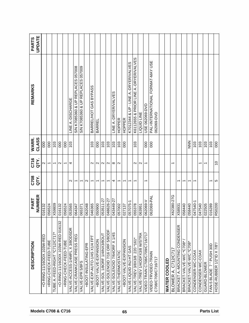
65Models C708 & C716 Parts List
DES
CR
IPTI
ON
PAR
TSU
PDA
TER
EMA
RK
SW
AR
R.
CLA
SSC
716
QTY
.C
708
QTY
.PA
RT
NU
MB
ER+O
-RIN
G-1
1/16
OD
X.1
03W
-RE
D01
6132
200
0+R
ING
-CH
EC
K-F
EE
D-T
UB
E05
6524
100
0TU
BE
A.-F
EE
D-R
IGH
T*C
712/
C71
7*X
5980
91
103
+O-R
ING
-11/
16O
DX
.103
W-R
ED
0161
3201
6132
200
0+R
ING
-CH
EC
K-F
EE
D-T
UB
E05
6524
100
0V
ALV
E-A
CC
ES
S-1
/4M
FLX
3/8O
DS
DR
0535
652
410
3LI
NE
A.-D
ISC
HA
RG
EV
ALV
E-C
RA
NK
CA
SE
PR
ES
SR
EG
0643
471
S/N
K70
8536
0&
UP
RE
PLA
CE
S05
7008
VA
LVE
-EP
R5/
8FS
0653
711
S/N
K70
8536
0&
UP
RE
PLA
CE
S05
7009
+BO
OT-
INS
ULA
TIN
G-E
PR
0620
482
VA
LVE
-EX
P-A
UTO
-1/4
SX
1/4
FPT
0463
651
210
3B
AR
RE
L/H
OT
GA
SB
YP
AS
S+B
OO
T-V
ALV
E-E
XP
AN
SIO
N05
0900
12
000
BA
RR
EL
VA
LVE
-SO
L1/
8OR
F1/
4IN
X3/
8OU
T05
3511
-27
12
103
VA
LVE
-SO
LEN
OID
7/16
OR
F5/
8OD
F04
8626
-27
12
103
VA
LVE
-SO
LEN
OID
7/64
OR
FX
1/4S
0434
49-2
74
810
3LI
NE
A.-D
RY
ER
/VA
LVE
SV
ALV
E-T
HE
RM
OS
TATI
C05
7002
12
103
HO
PP
ER
+BO
OT-
VA
LVE
-EX
PA
NS
ION
0271
371
000
HO
PP
ER
VA
LVE
-LIQ
UID
INJ-
HT
GA
S05
7075
-11
K70
1234
4&
UP
-LIN
EA
.-DR
YE
R/V
ALV
ES
VA
LVE
-TR
EV
3/8X
3/8
220
*161
*05
5378
12
103
K61
1265
5&
PR
IOR
LIN
EA
.-DR
YE
R/V
ALV
ES
VA
LVE
-TR
EV
1/4O
DFX
3/8
W/S
TRA
0639
512
LIQ
UID
LIN
EV
IDE
O-T
RA
INC
708/
C70
9/C
716/
717
0620
69-V
11
000
US
E06
2069
-DV
DV
IDE
O-T
RV
IDE
O-T
RA
INC
708/
C70
9/C
716/
717
0620
69-P
AL
000
PA
L=IN
TER
NA
TIO
NA
LFO
RM
AT-
MA
YU
SE
0620
69-D
VD
WA
TER
CO
OLE
DB
LOW
ER
A.C
712/
C71
7X
6238
0-27
G1
BR
AC
KE
TA
.-MO
UN
TIN
GC
ON
DE
NS
ER
X58
931
1B
RA
CK
ET-
VA
LVE
-W/C
*C70
8*/
0584
401
BR
AC
KE
T-V
ALV
E-W
/C*C
708*
0584
401
NN
NC
ON
DE
NS
ER
-WC
-CO
AX
0475
40-1
110
3C
ON
DE
NS
ER
-WC
-CO
AX
0475
401
103
GU
AR
D-B
LOW
ER
0225
051
103
FAN
-5B
LAD
E7
"PU
SH
30D
0162
891
103
HO
SE
-RU
BB
ER
1/2"
IDX
7/8"
/R
5020
05
1000
0
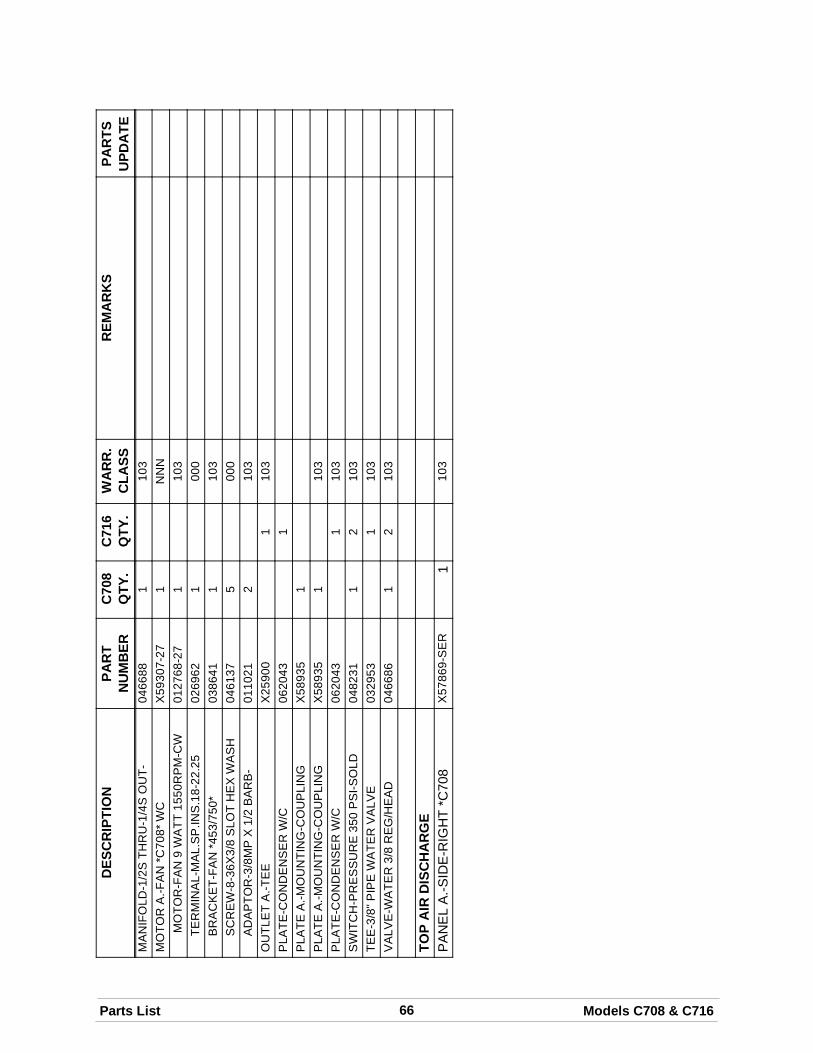
66Parts List Models C708 & C716
DES
CR
IPTI
ON
PAR
TSU
PDA
TER
EMA
RK
SW
AR
R.
CLA
SSC
716
QTY
.C
708
QTY
.PA
RT
NU
MB
ERM
AN
IFO
LD-1
/2S
THR
U-1
/4S
OU
T-04
6688
110
3M
OTO
RA
.-FA
N*C
708*
WC
X59
307-
271
NN
NM
OTO
R-F
AN
9W
ATT
1550
RP
M-C
W01
2768
-27
110
3TE
RM
INA
L-M
AL.
SP
.INS
.18-
22.2
502
6962
100
0B
RA
CK
ET-
FAN
*453
/750
*03
8641
110
3S
CR
EW
-8-3
6X3/
8S
LOT
HE
XW
AS
H04
6137
500
0A
DA
PTO
R-3
/8M
PX
1/2
BA
RB
-01
1021
210
3O
UTL
ET
A.-T
EE
X25
900
110
3P
LATE
-CO
ND
EN
SE
RW
/C06
2043
1P
LATE
A.-M
OU
NTI
NG
-CO
UP
LIN
GX
5893
51
PLA
TEA
.-MO
UN
TIN
G-C
OU
PLI
NG
X58
935
110
3P
LATE
-CO
ND
EN
SE
RW
/C06
2043
110
3S
WIT
CH
-PR
ES
SU
RE
350
PS
I-SO
LD04
8231
12
103
TEE
-3/8
"PIP
EW
ATE
RV
ALV
E03
2953
110
3V
ALV
E-W
ATE
R3/
8R
EG
/HE
AD
0466
861
210
3
TOP
AIR
DIS
CH
AR
GE
PA
NE
LA
.-SID
E-R
IGH
T*C
708
X57
869-
SE
R1
103
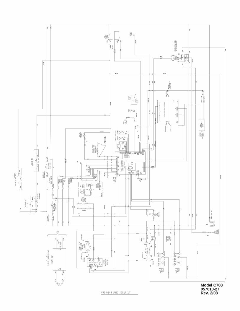
Model C708057010-27Rev. 2/08
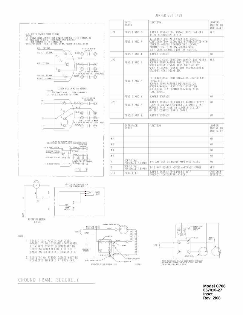
Model C708057010-27InsetRev. 2/08
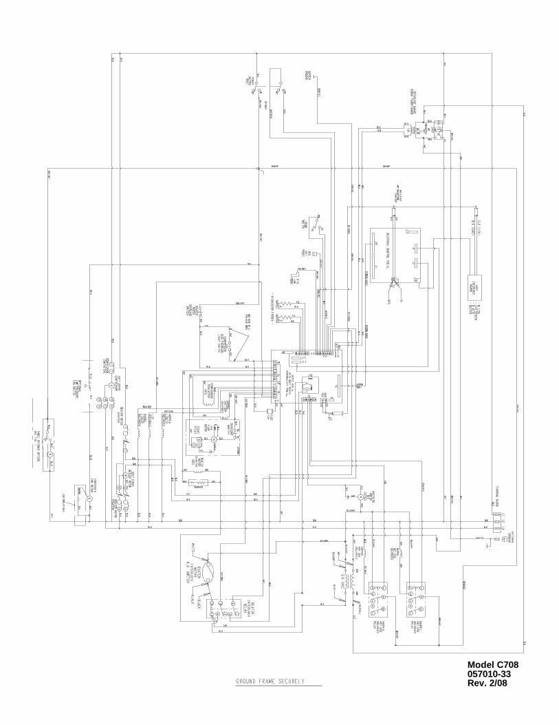
Model C708057010-33Rev. 2/08
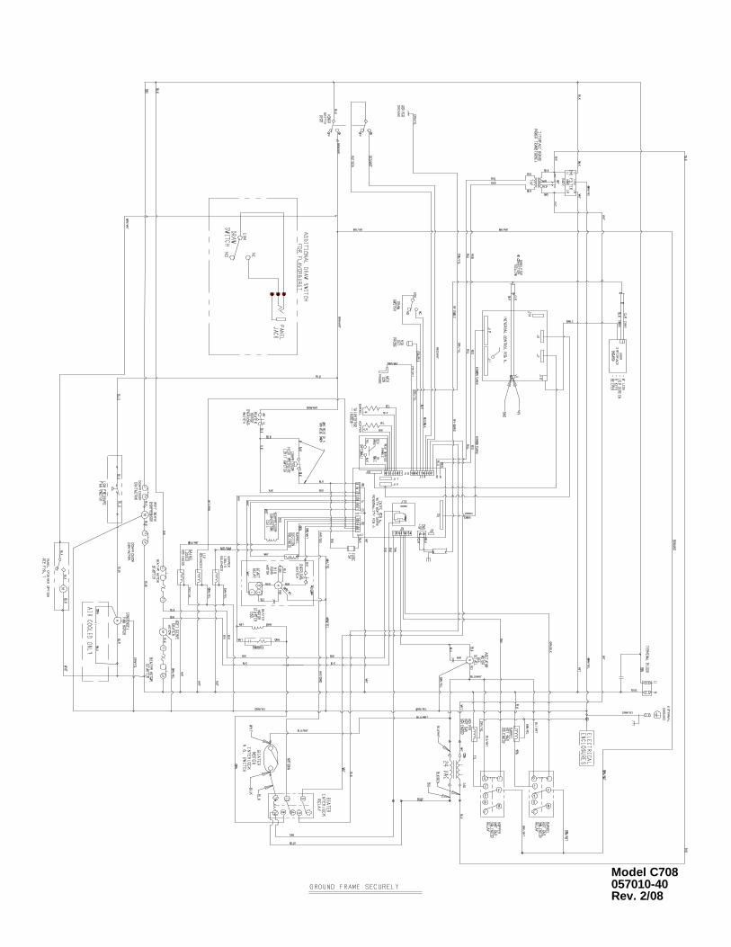
Model C708057010-40Rev. 2/08
Model C708057010-58Rev. 2/08
Model C716059900-27Rev. 2/08
Model C716059900-27InsetRev. 2/08
Model C716059900-33Rev. 2/08
Model C716059900-40Rev. 2/08
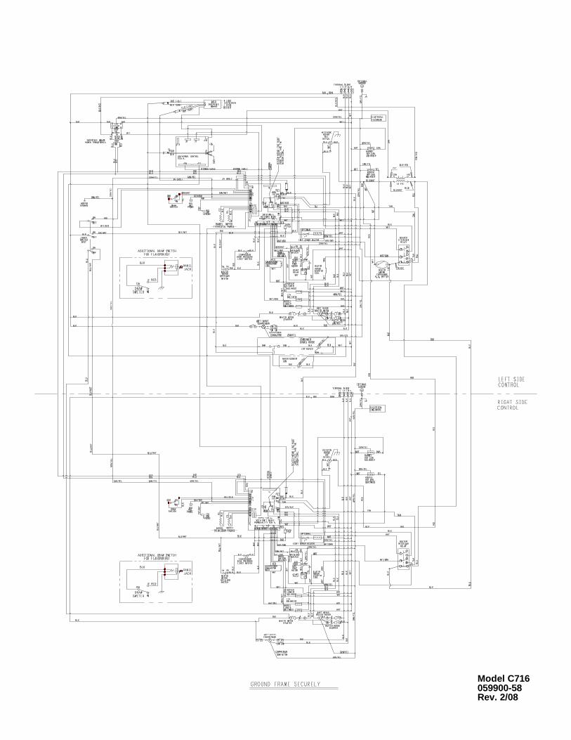
Model C716059900-58Rev. 2/08