task: mccs.18.01 (core) perform compass … · ... given a lensatic compass and a known line of...
TRANSCRIPT

1-18-1
TASK: MCCS.18.01 (CORE) PERFORM COMPASS HANDLING PROCEDURES
CONDITION: GIVEN A LENSATIC COMPASS AND A KNOW N LINE OF DIRECTION/AZIMUTH.
STANDARD: TO ENSURE CALIBRATION W ITHIN THREE DEGREES.
EVALUATION GUIDELINES TO BE USED DURING TRAINING:
Condition: The Marine is provided a lensatic compass and known line of direction.
Standard: The Marine must inspect the three major parts and measure the accuracy of a lensatic compass.
PERFORMANCE STEPS:
1. Inspect the three major parts of the lensatic compass.
a. The three major parts of the lensatic compass are the cover, base, and lens. The diagram below illustrates the lensatic compass.
(1) Cover. The compass cover protects the floating dial. It contains the sighting wire (front sight) and two luminous sightingslots or dots used for night navigation.
(2) Base. The body of the compass contains the following movable parts: floating dial, bezel ring, and magnetic arrow.
(a) The floating dial is mounted on a pivot so it can rotate freely when the compass is held leveled. Printed on the dial in
luminous figures are an arrow and the letters E and W . The luminous magnetic arrow always points to magnetic north
and the letters fall at east (E) 90° and west (W) 270° on the dial. There are two scales; the outer scale denotes mils and
the inner scale (normally in red) denotes degrees.
(b)Encasing the floating dial is a glass containing a fixed black index line.
(c) The bezel ring is a ratchet device that clicks when turned. It contains 120 clicks when rotated fully. Each click is equal
to 3°. The short luminous line that is used in conjunction with the north-seeking arrow during navigation is contained in
the glass face of the bezel ring.
1-18-2
(d) The thumb loop is attached to the base of the compass.
(3) Rear sight or Lens . The rear sight contains a lens and sighting slot. The lens is used to read the dial. The sighting slot is
used in conjunction with the sighting wire for sighting on objects. The rear sight also serves as a lock and clamps the dial
when closed for its protection. The rear sight must be opened more than 45° to allow the dial to float freely.
NOTE: When opened, the straightedge on the left side of the compass has a coordinate scale; the scale is 1:50,000
in newer compasses.
WARNING: Some older compasses will have a 1:25,000 scale. This scale can be used with a 1:50,000-scale map, but
the values read must be halved. Check the scale.
b. A detailed inspection is required when first obtaining and using a compass. One of the most important parts to check is the
floating dial, which contains the magnetic arrow. The user must also make sure the sighting wire is straight, the glass and crystalparts are not broken, the numbers on the dial are readable, and most important, that the dial does not stick.
2. Maintain prescribed separation between the lensatic compass and metal objects and electrical sources.
- Metal objects and electrical sources can affect the performance of a compass. Nonmagnetic metals and alloys do not affect
compass readings. The following separation distances are suggested to ensure proper functioning of a compass:
(1) High-tension power lines … … … … … … … … … … … 55 meters
(2) Field gun, truck, or tank … … … … … … … … … … … 18 meters
(3) Telegraph or telephone wires
and barbed wire … … … … … … … … … … … … … … … 10 meters
(4) Machinegun … … … … … … … … … … … … … … … … 2 meters
(5) Steel helmet or rifle … … … … … … … … … … … … … 1/2 meter
3. Measure the accuracy of the lensatic compass.
- A compass in good working condition is very accurate. However, a compass has to be checked periodically on a known line of
direction, such as a surveyed azimuth using a declination station. Do not use compasses with more than 3°+ variation.
4. Protect the lensatic compass.
- If traveling with the compass unfolded, make sure the rear sight is fully folded down onto the bezel ring. This will lock thefloating dial and prevent vibration, as well as protect the crystal and rear sight from damage.
REFERENCE(S):
FM 21-26, Map Reading and Land Navigation
1-18-3
TASK: MCCS.18.02 (CORE) PERFORM LAND NAVIGATION USING A COMPASS
CONDITION: GIVEN THE REQUIREMENT.
STANDARD: TO DEMONSTRATE UNDERSTANDING PER THE REFERENCE.
EVALUATION GUIDELINES TO BE USED DURING TRAINING:
Conditions: Given 782-gear, compass, and an azimuth and distance to designated points.
Standard: To traverse two out of three designated points.
PERFORMANCE STEPS:
1. Determine daylight or darkness pace counts.
a. A pace is equal to one natural step, about 30 inches long. To accurately use the pace count method, you must know how many
paces it takes you to walk 100 meters. To determine this, you must walk an accurately measured course and count the number of
paces you take. A pace course can be as short as 100 meters or as long as 600 meters. The pace course, regardless of length,
must be on similar terrain to what you will be walking over. It does no good to walk a course on flat terrain and then try to use
that pace count on hilly terrain. To determine your pace count on a 600-meter course, count the paces it takes you to walk the 600
meters, then divide the total paces by 6. The answer will give you the average paces it takes you to walk 100 meters. It isimportant that each person who navigates while dismounted knows his pace count.
(1) There are many methods to keep track of the distance traveled when using the pace count. Some of these methods include
putting a pebble in your pocket every time you have walked 100 meters according to your pace count; tying knots on a string;
or putting marks in a notebook. Do not try to remember the count; always use one of these methods or design your own
method.
(2) Certain conditions affect your pace count in the field, and you must allow for them by making adjustments.
(a) Slopes. Your pace will lengthen on a downslope and shorten on an upgrade. Keeping this in mind, if it normally takes you
120 paces to walk 100 meters, your pace count may increase to 130 or more when walking up a slope.
(b) Winds. A head wind shortens the pace and a tail wind increases it.
(c) Surfaces. Sand, gravel, mud, snow, and similar surface materials tend to shorten the pace.
(d) Elements. Falling snow, rain, or ice causes the pace to be reduced in length.
(e) Clothing. Excess clothing and boots with poor traction affect the pace length.
(f) Visibility. Poor visibility, such as in fog, rain, or darkness, will shorten your pace.
b. The basic technique used for nighttime land navigation is dead reckoning with several compasses recommended. The point man
will be in front of the navigator but just a few steps away for easy control of the azimuth. Smaller steps are taken during night
navigation so remember the pace count will be different. It is recommended that a pace count obtained by using a predetermined
100-meter pace course be used at night.
2. Preset and follow a prescribed azimuth.
- Although different models of the lensatic compass vary somewhat in the details of their use, the principles are the same.
(1) During daylight hours or with a light source
(a) Hold the compass level in the palm of the hand.
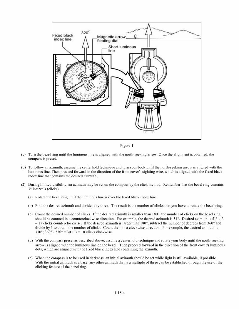
(b) Rotate it until the desired azimuth falls under the fixed black index line (e.g., 320°), maintaining the azimuth asprescribed (figure 1).
1-18-4
Figure 1
(c) Turn the bezel ring until the luminous line is aligned with the north-seeking arrow. Once the alignment is obtained, thecompass is preset.
(d) To follow an azimuth, assume the centerhold technique and turn your body until the north-seeking arrow is aligned with the
luminous line. Then proceed forward in the direction of the front cover's sighting wire, which is aligned with the fixed black
index line that contains the desired azimuth.
(2) During limited visibility, an azimuth may be set on the compass by the click method. Remember that the bezel ring contains
3° intervals (clicks).
(a) Rotate the bezel ring until the luminous line is over the fixed black index line.
(b) Find the desired azimuth and divide it by three. The result is the number of clicks that you have to rotate the bezel ring.
(c) Count the desired number of clicks. If the desired azimuth is smaller than 180°, the number of clicks on the bezel ring
should be counted in a counterclockwise direction. For example, the desired azimuth is 51°. Desired azimuth is 51° ÷ 3
= 17 clicks counterclockwise. If the desired azimuth is larger than 180°, subtract the number of degrees from 360° and
divide by 3 to obtain the number of clicks. Count them in a clockwise direction. For example, the desired azimuth is
330°; 360° - 330° = 30 ÷ 3 = 10 clicks clockwise.
(d) With the compass preset as described above, assume a centerhold technique and rotate your body until the north-seeking
arrow is aligned with the luminous line on the bezel. Then proceed forward in the direction of the front cover's luminousdots, which are aligned with the fixed black index line containing the azimuth.
(e) When the compass is to be used in darkness, an initial azimuth should be set while light is still available, if possible.
With the initial azimuth as a base, any other azimuth that is a multiple of three can be established through the use of the
clicking feature of the bezel ring.
1-18-5
NOTES: Sometimes the desired azimuth is not exactly divisible by three, causing an option of rounding up or
rounding down. If the azimuth is rounded up, this causes an increase in the value of the azimuth, and
the object is found on the left. If the azimuth is rounded down, this causes a decrease in the value of the
azimuth, and the object is found on the right.
3. Bypass an obstacle, as required.
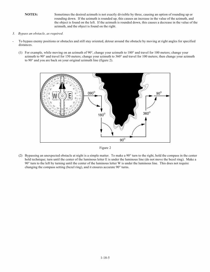
- To bypass enemy positions or obstacles and still stay oriented, detour around the obstacle by moving at right angles for specifieddistances.
(1) For example, while moving on an azimuth of 90°, change your azimuth to 180° and travel for 100 meters; change your
azimuth to 90° and travel for 150 meters; change your azimuth to 360° and travel for 100 meters; then change your azimuth
to 90° and you are back on your original azimuth line (figure 2).
Figure 2
(2) Bypassing an unexpected obstacle at night is a simple matter. To make a 90° turn to the right, hold the compass in the center
hold technique; turn until the center of the luminous letter E is under the luminous line (do not move the bezel ring). Make a
90° turn to the left by turning until the center of the luminous letter W is under the luminous line. This does not require
changing the compass setting (bezel ring), and it ensures accurate 90° turns.
1-18-6
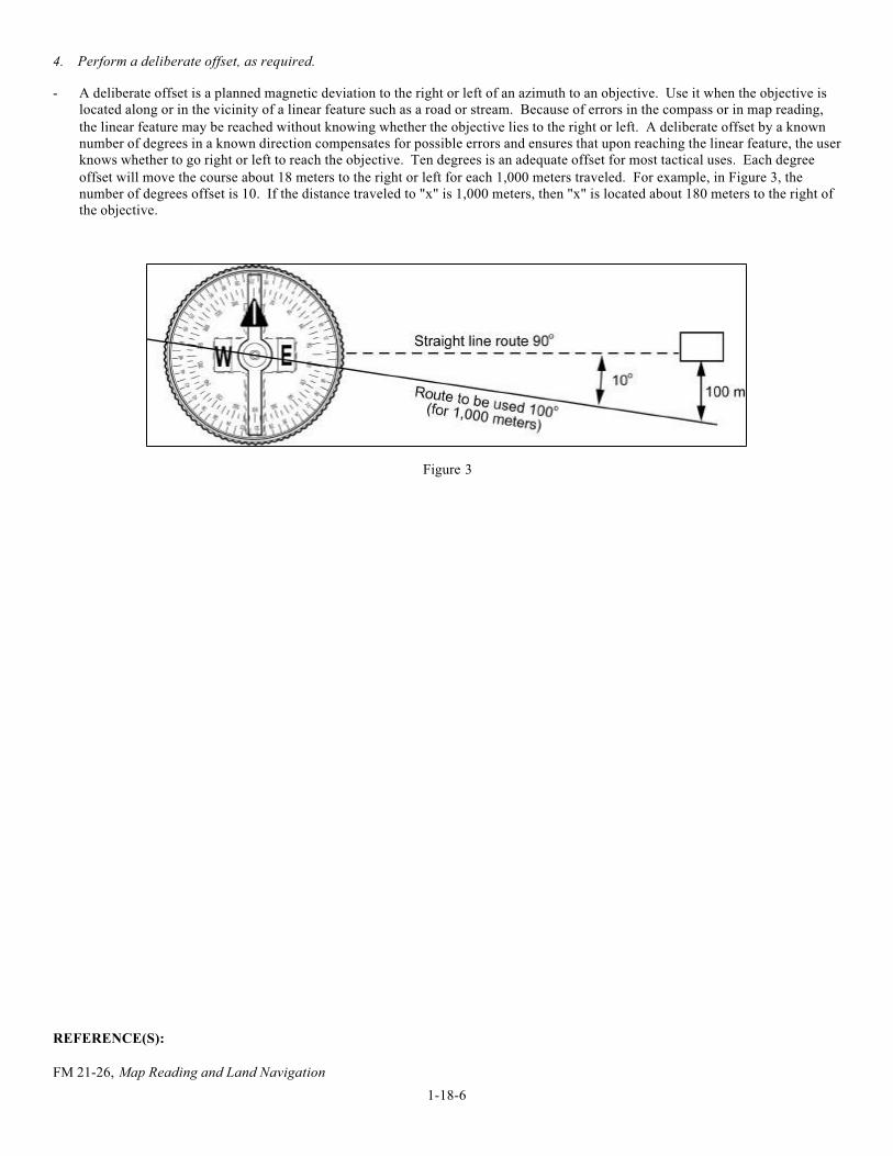
4. Perform a deliberate offset, as required.
- A deliberate offset is a planned magnetic deviation to the right or left of an azimuth to an objective. Use it when the objective is
located along or in the vicinity of a linear feature such as a road or stream. Because of errors in the compass or in map reading,
the linear feature may be reached without knowing whether the objective lies to the right or left. A deliberate offset by a known
number of degrees in a known direction compensates for possible errors and ensures that upon reaching the linear feature, the user
knows whether to go right or left to reach the objective. Ten degrees is an adequate offset for most tactical uses. Each degree
offset will move the course about 18 meters to the right or left for each 1,000 meters traveled. For example, in Figure 3, the
number of degrees offset is 10. If the distance traveled to "x" is 1,000 meters, then "x" is located about 180 meters to the right of
the objective.
Figure 3
REFERENCE(S):
FM 21-26, Map Reading and Land Navigation
1-18-7
TASK: MCCS.18.03 (CORE) PERFORM BASIC MAP READING
CONDITIONS: GIVEN THE REQUIREMENT.
STANDARDS: TO DEMONSTRATE UNDERSTANDING PER THE REFERENCE.
EVALUATION GUIDELINES TO BE USED DURING TRAINING:
Conditions: The Marine is provided a 1:50,000 map, a coordinate scale, a protractor, paper, a pen, and six-digit gridcoordinates to various natural and manmade features.
Standard: The Marine must correctly identify the six colors of a map and what each color represents; accurately
determine the six-digit grid coordinate of a specified point on a map to within +/- 100 meters; accurately
plot a six-digit grid coordinate on the map to within +/- 100 meters; correctly identify the following
natural features on the map: hill, finger, draw, saddle, ridge, and cliff, correctly measure the straight line
distance between two points on the map to within +/- 100 meters (the two points must be at least 4,000
meters apart); and correctly measure the curved line distance between two points on the map to within +/-
200 meters (the two points must be at least 4,000 meters apart and must be along a road or other curvedlinear feature) per the reference.
Administrative Notes: When identifying a finger, a draw, and a ridge on a map, the Marine must be provided two six-digit grid
coordinates, one for each end of the specified feature.
PERFORMANCE STEPS:
1. Identify the following marginal information found on a topographical map: declination diagram, bar scale, contour interval note,
and legend.
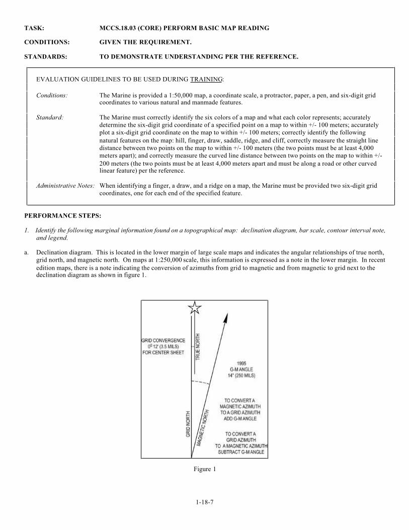
a. Declination diagram. This is located in the lower margin of large scale maps and indicates the angular relationships of true north,
grid north, and magnetic north. On maps at 1:250,000 scale, this information is expressed as a note in the lower margin. In recent
edition maps, there is a note indicating the conversion of azimuths from grid to magnetic and from magnetic to grid next to thedeclination diagram as shown in figure 1.
Figure 1

1-18-8
b. Bar scale. These are located in the center of the lower margin. They are rulers used to convert map distance to ground distance as
shown in figure 2. Maps have three or more bar scales, each in a different unit of measure. Care should be exercised when usingthe scales, especially in the selection of the unit of measure that is needed.
Figure 2
c. Contour interval note. This note is found in the center of the lower margin normally below the bar scales. It states the vertical
distance between adjacent contour lines of the map. When supplementary contours are used, the interval is indicated. In recentedition maps, the contour interval is given in meters instead of feet.
d. Legend. The legend is located in the lower left margin. It illustrates and identifies the topographic symbols used to depict some
of the more prominent features on the map. The symbols are not always the same on every map. Always refer to the legend to
avoid errors when reading a map.
2. Identify the three types of contour lines found on a topographical map.
- Contour lines are the most common method of showing relief and elevation on a standard topographic map. A contour line
represents an imaginary line on the ground, above or below sea level. All points on the contour line are at the same elevation.
The elevation represented by contour lines is the vertical distance above or below sea level. The three types of contour lines used
on a standard topographic map are shown in figure 3:
Figure 3
(1) Index. Starting at zero elevation or mean sea level, every fifth contour line is a heavier line. These are known as index
contour lines. Normally, each index contour line is numbered at some point. This number is the elevation of that line.
1-18-9
(2) Intermediate. The contour lines falling between the index contour lines are called intermediate contour lines. These lines are
finer and do not have their elevations given. There are normally four intermediate contour lines between index contour lines.
(2) Supplementary. These contour lines resemble dashes. They show changes in elevation of at least one-half the contour
interval. These lines are normally found where there is very little change in elevation, such as on level terrain.
3. Identify the 10 terrain features found on a topographical map.
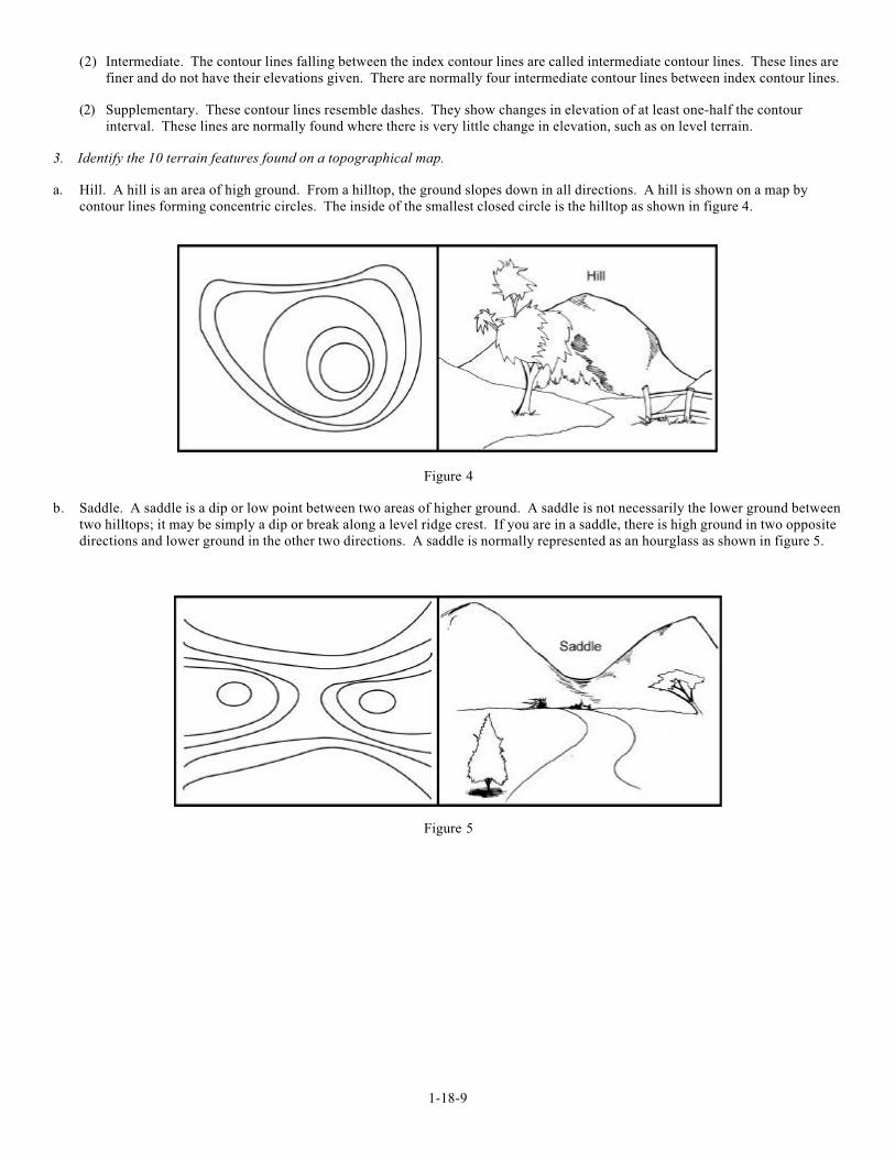
a. Hill. A hill is an area of high ground. From a hilltop, the ground slopes down in all directions. A hill is shown on a map by
contour lines forming concentric circles. The inside of the smallest closed circle is the hilltop as shown in figure 4.
Figure 4
b. Saddle. A saddle is a dip or low point between two areas of higher ground. A saddle is not necessarily the lower ground between
two hilltops; it may be simply a dip or break along a level ridge crest. If you are in a saddle, there is high ground in two opposite
directions and lower ground in the other two directions. A saddle is normally represented as an hourglass as shown in figure 5.
Figure 5
1-18-10
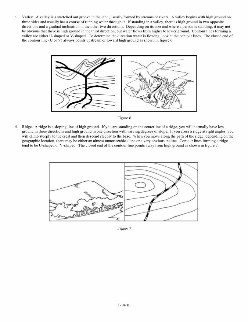
c. Valley. A valley is a stretched out groove in the land, usually formed by streams or rivers. A valley begins with high ground on
three sides and usually has a course of running water through it. If standing in a valley, there is high ground in two opposite
directions and a gradual inclination in the other two directions. Depending on its size and where a person is standing, it may not
be obvious that there is high ground in the third direction, but water flows from higher to lower ground. Contour lines forming a
valley are either U-shaped or V-shaped. To determine the direction water is flowing, look at the contour lines. The closed end ofthe contour line (U or V) always points upstream or toward high ground as shown in figure 6.
Figure 6
d. Ridge. A ridge is a sloping line of high ground. If you are standing on the centerline of a ridge, you will normally have low
ground in three directions and high ground in one direction with varying degrees of slope. If you cross a ridge at right angles, you
will climb steeply to the crest and then descend steeply to the base. When you move along the path of the ridge, depending on the
geographic location, there may be either an almost unnoticeable slope or a very obvious incline. Contour lines forming a ridge
tend to be U-shaped or V-shaped. The closed end of the contour line points away from high ground as shown in figure 7.
Figure 7
1-18-11
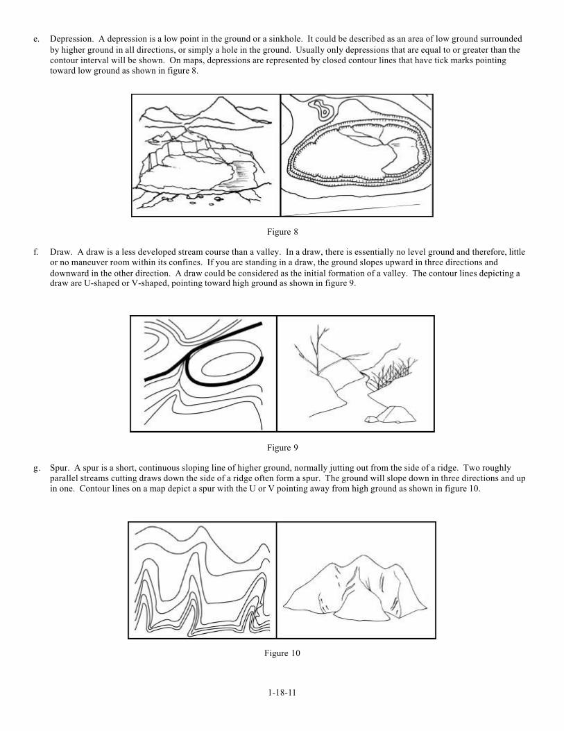
e. Depression. A depression is a low point in the ground or a sinkhole. It could be described as an area of low ground surrounded
by higher ground in all directions, or simply a hole in the ground. Usually only depressions that are equal to or greater than the
contour interval will be shown. On maps, depressions are represented by closed contour lines that have tick marks pointing
toward low ground as shown in figure 8.
Figure 8
f. Draw. A draw is a less developed stream course than a valley. In a draw, there is essentially no level ground and therefore, little
or no maneuver room within its confines. If you are standing in a draw, the ground slopes upward in three directions and
downward in the other direction. A draw could be considered as the initial formation of a valley. The contour lines depicting adraw are U-shaped or V-shaped, pointing toward high ground as shown in figure 9.
Figure 9
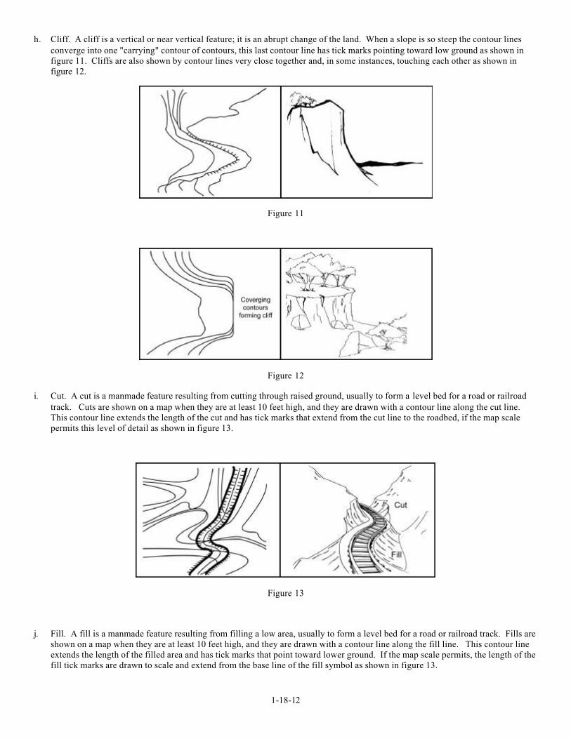
g. Spur. A spur is a short, continuous sloping line of higher ground, normally jutting out from the side of a ridge. Two roughly
parallel streams cutting draws down the side of a ridge often form a spur. The ground will slope down in three directions and up
in one. Contour lines on a map depict a spur with the U or V pointing away from high ground as shown in figure 10.
Figure 10
1-18-12
h. Cliff. A cliff is a vertical or near vertical feature; it is an abrupt change of the land. When a slope is so steep the contour lines
converge into one "carrying" contour of contours, this last contour line has tick marks pointing toward low ground as shown in
figure 11. Cliffs are also shown by contour lines very close together and, in some instances, touching each other as shown in
figure 12.
Figure 11
Figure 12
i. Cut. A cut is a manmade feature resulting from cutting through raised ground, usually to form a level bed for a road or railroad
track. Cuts are shown on a map when they are at least 10 feet high, and they are drawn with a contour line along the cut line.
This contour line extends the length of the cut and has tick marks that extend from the cut line to the roadbed, if the map scale
permits this level of detail as shown in figure 13.
Figure 13
j. Fill. A fill is a manmade feature resulting from filling a low area, usually to form a level bed for a road or railroad track. Fills are
shown on a map when they are at least 10 feet high, and they are drawn with a contour line along the fill line. This contour line
extends the length of the filled area and has tick marks that point toward lower ground. If the map scale permits, the length of the
fill tick marks are drawn to scale and extend from the base line of the fill symbol as shown in figure 13.
1-18-13
4. Identify the features represented by the six colors used on military maps.
a. Black. Indicates cultural (manmade) features such as buildings and roads, surveyed spot elevations, and all labels.
b. Red Brown. The colors red and brown are combined to identify cultural features, all relief features, non-surveyed spot elevations,and elevations such as the contour lines on red-light readable maps.
c. Blue. Identifies hydrograph or water features such as lakes, swamps, rivers, and drainage.
d. Green. Identifies vegetation with military significance such as woods, orchards, and vineyards.
e. Brown. Identifies all relief features and elevation such as contours on older edition maps and cultivated land on red-light readable
maps.
f. Red. Classifies cultural features such as populated areas, main roads, and boundaries on older maps.
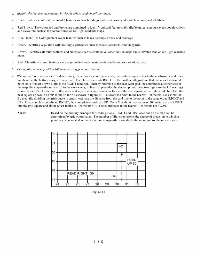
5. Plot a point on a map within 100 meters using grid coordinates.
a. Without a Coordinate Scale. To determine grids without a coordinate scale, the reader simply refers to the north-south grid lines
numbered at the bottom margin of any map. Then he or she reads RIGHT to the north-south grid line that precedes the desired
point (this first set of two digits is the RIGHT reading). Then by referring to the east-west grid lines numbered at either side of
the map, the map reader moves UP to the east-west grid line that precedes the desired point (these two digits are the UP reading).
Coordinates 3050, locate the 1,000-meter grid square in which point C is located; the next square to the right would be 3150; the
next square up would be 3051; and so forth as shown in figure 14. To locate the point to the nearest 100 meters, use estimation.
By mentally dividing the grid square in tenths, estimate the distance from the grid line to the point in the same order (RIGHT and
UP). Give complete coordinate RIGHT, then complete coordinate UP. Point C is about two-tenths or 200 meters to the RIGHTinto the grid square and about seven-tenths or 700 meters UP. The coordinates to the nearest 100 meters are 302507.
NOTE: Based on the military principle for reading maps (RIGHT and UP), locations on the map can be
determined by grid coordinates. The number of digits represents the degree of precision to which a
point has been located and measured on a map— the more digits the more precise the measurement.
Figure 14
1-18-14
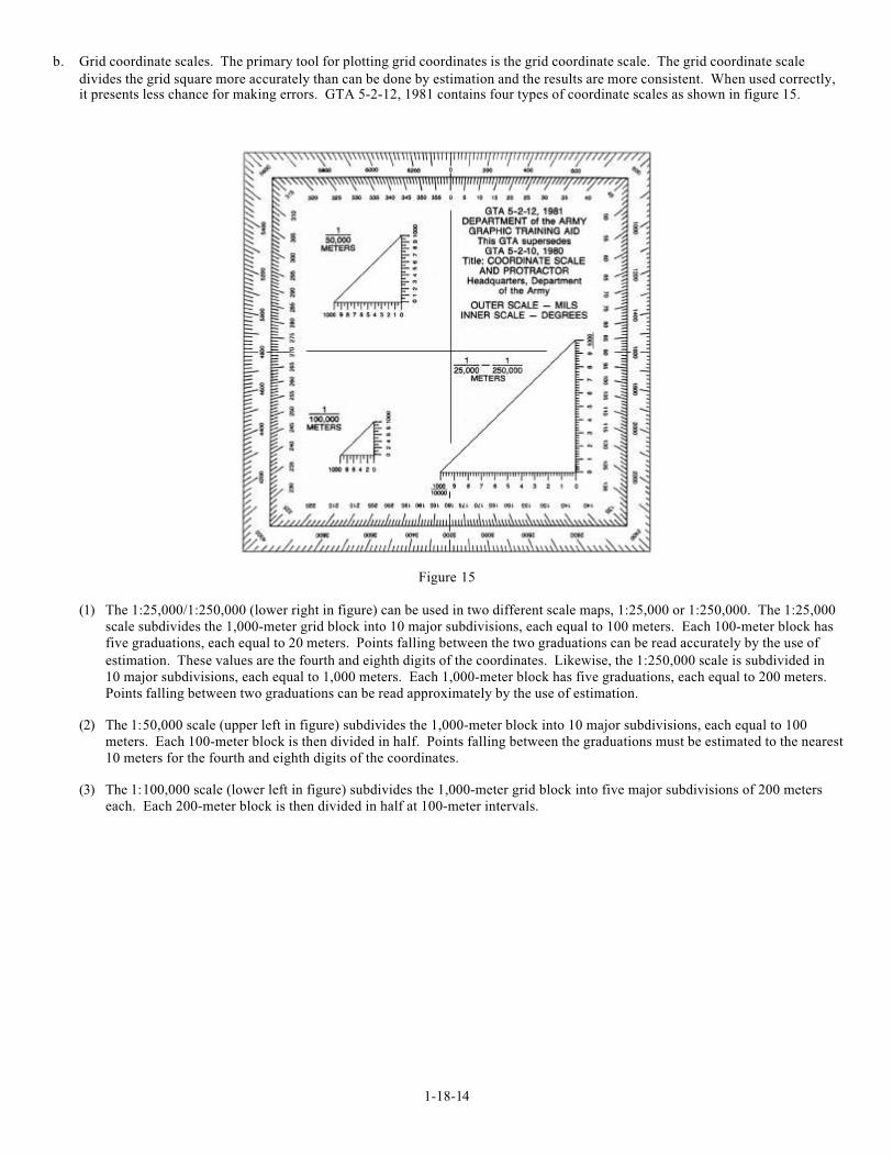
b. Grid coordinate scales. The primary tool for plotting grid coordinates is the grid coordinate scale. The grid coordinate scale
divides the grid square more accurately than can be done by estimation and the results are more consistent. When used correctly,it presents less chance for making errors. GTA 5-2-12, 1981 contains four types of coordinate scales as shown in figure 15.
Figure 15
(1) The 1:25,000/1:250,000 (lower right in figure) can be used in two different scale maps, 1:25,000 or 1:250,000. The 1:25,000
scale subdivides the 1,000-meter grid block into 10 major subdivisions, each equal to 100 meters. Each 100-meter block has
five graduations, each equal to 20 meters. Points falling between the two graduations can be read accurately by the use of
estimation. These values are the fourth and eighth digits of the coordinates. Likewise, the 1:250,000 scale is subdivided in
10 major subdivisions, each equal to 1,000 meters. Each 1,000-meter block has five graduations, each equal to 200 meters.
Points falling between two graduations can be read approximately by the use of estimation.
(2) The 1:50,000 scale (upper left in figure) subdivides the 1,000-meter block into 10 major subdivisions, each equal to 100
meters. Each 100-meter block is then divided in half. Points falling between the graduations must be estimated to the nearest
10 meters for the fourth and eighth digits of the coordinates.
(3) The 1:100,000 scale (lower left in figure) subdivides the 1,000-meter grid block into five major subdivisions of 200 meters
each. Each 200-meter block is then divided in half at 100-meter intervals.
1-18-15
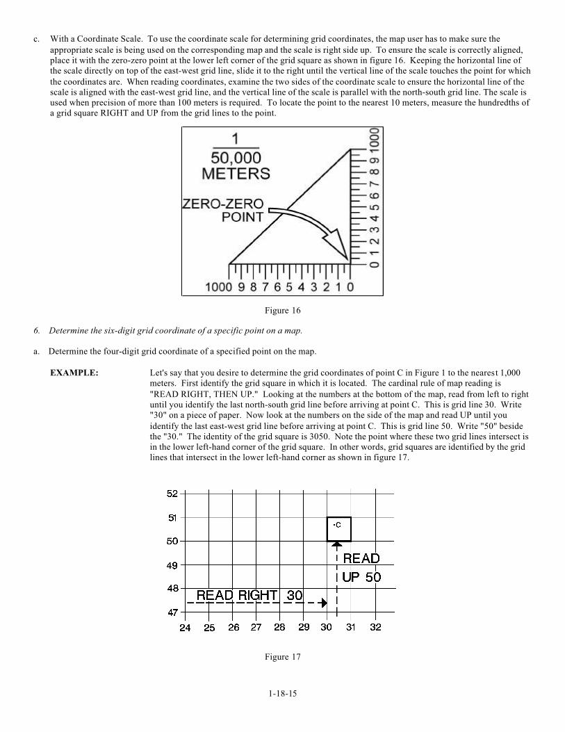
c. With a Coordinate Scale. To use the coordinate scale for determining grid coordinates, the map user has to make sure the
appropriate scale is being used on the corresponding map and the scale is right side up. To ensure the scale is correctly aligned,
place it with the zero-zero point at the lower left corner of the grid square as shown in figure 16. Keeping the horizontal line of
the scale directly on top of the east-west grid line, slide it to the right until the vertical line of the scale touches the point for which
the coordinates are. When reading coordinates, examine the two sides of the coordinate scale to ensure the horizontal line of the
scale is aligned with the east-west grid line, and the vertical line of the scale is parallel with the north-south grid line. The scale is
used when precision of more than 100 meters is required. To locate the point to the nearest 10 meters, measure the hundredths of
a grid square RIGHT and UP from the grid lines to the point.
Figure 16
6. Determine the six-digit grid coordinate of a specific point on a map.
a. Determine the four-digit grid coordinate of a specified point on the map.
EXAMPLE: Let's say that you desire to determine the grid coordinates of point C in Figure 1 to the nearest 1,000
meters. First identify the grid square in which it is located. The cardinal rule of map reading is
"READ RIGHT, THEN UP." Looking at the numbers at the bottom of the map, read from left to right
until you identify the last north-south grid line before arriving at point C. This is grid line 30. Write
"30" on a piece of paper. Now look at the numbers on the side of the map and read UP until you
identify the last east-west grid line before arriving at point C. This is grid line 50. Write "50" beside
the "30." The identity of the grid square is 3050. Note the point where these two grid lines intersect is
in the lower left-hand corner of the grid square. In other words, grid squares are identified by the grid
lines that intersect in the lower left-hand corner as shown in figure 17.
Figure 17
1-18-16
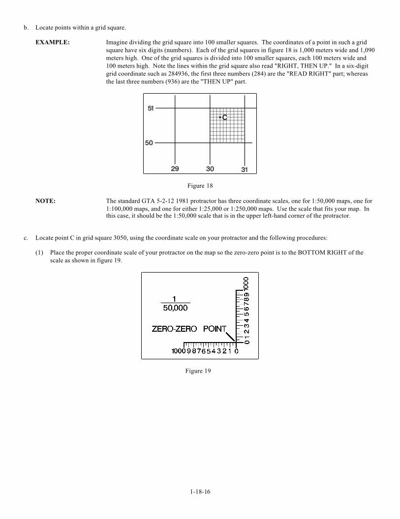
b. Locate points within a grid square.
EXAMPLE: Imagine dividing the grid square into 100 smaller squares. The coordinates of a point in such a grid
square have six digits (numbers). Each of the grid squares in figure 18 is 1,000 meters wide and 1,090
meters high. One of the grid squares is divided into 100 smaller squares, each 100 meters wide and
100 meters high. Note the lines within the grid square also read "RIGHT, THEN UP." In a six-digit
grid coordinate such as 284936, the first three numbers (284) are the "READ RIGHT" part; whereas
the last three numbers (936) are the "THEN UP" part.
Figure 18
NOTE: The standard GTA 5-2-12 1981 protractor has three coordinate scales, one for 1:50,000 maps, one for
1:100,000 maps, and one for either 1:25,000 or 1:250,000 maps. Use the scale that fits your map. Inthis case, it should be the 1:50,000 scale that is in the upper left-hand corner of the protractor.
c. Locate point C in grid square 3050, using the coordinate scale on your protractor and the following procedures:
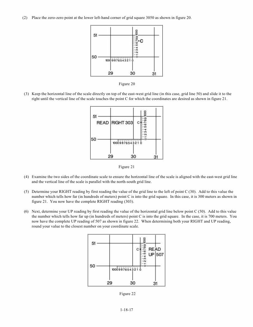
(1) Place the proper coordinate scale of your protractor on the map so the zero-zero point is to the BOTTOM RIGHT of the
scale as shown in figure 19.
Figure 19
1-18-17
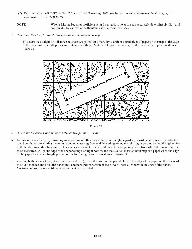
(2) Place the zero-zero point at the lower left-hand corner of grid square 3050 as shown in figure 20.
Figure 20
(3) Keep the horizontal line of the scale directly on top of the east-west grid line (in this case, grid line 50) and slide it to the
right until the vertical line of the scale touches the point C for which the coordinates are desired as shown in figure 21.
Figure 21
(4) Examine the two sides of the coordinate scale to ensure the horizontal line of the scale is aligned with the east-west grid line
and the vertical line of the scale is parallel with the north-south grid line.
(5) Determine your RIGHT reading by first reading the value of the grid line to the left of point C (30). Add to this value the
number which tells how far (in hundreds of meters) point C is into the grid square. In this case, it is 300 meters as shown in
figure 21. You now have the complete RIGHT reading (303).
(6) Next, determine your UP reading by first reading the value of the horizontal grid line below point C (50). Add to this value
the number which tells how far up (in hundreds of meters) point C is into the grid square. In the case, it is 700 meters. You
now have the complete UP reading of 507 as shown in figure 22. When determining both your RIGHT and UP reading,
round your value to the closest number on your coordinate scale.
Figure 22
1-18-18
(7) By combining the RIGHT reading (303) with the UP reading (507), you have accurately determined the six-digit grid
coordinate of point C (303507).
NOTE: When a Marine becomes proficient at land navigation, he or she can accurately determine six-digit grid
coordinates by estimation without the use of a coordinate scale.
7. Determine the straight-line distance between two points on a map.
- To determine straight-line distance between two points on a map, lay a straight-edged piece of paper on the map so the edge
of the paper touches both points and extends past them. Make a tick mark on the edge of the paper at each point as shown in
figure 23.
Figure 23
8. Determine the curved-line distance between two points on a map.
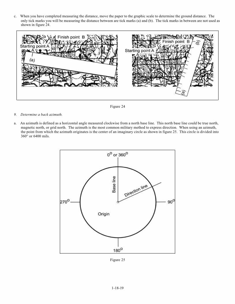
a. To measure distance along a winding road, stream, or other curved line, the straightedge of a piece of paper is used. In order to
avoid confusion concerning the point to begin measuring from and the ending point, an eight-digit coordinate should be given for
both the starting and ending points. Place a tick mark on the paper and map at the beginning point from which the curved line is
to be measured. Align the edge of the paper along a straight portion and make a tick mark on both map and paper when the edgeof the paper leaves the straight portion of the line being measured as shown in figure 24.
b. Keeping both tick marks together (on paper and map), place the point of the pencil close to the edge of the paper on the tick mark
to hold it in place and pivot the paper until another straight portion of the curved line is aligned with the edge of the paper.
Continue in this manner until the measurement is completed.
1-18-19
c. When you have completed measuring the distance, move the paper to the graphic scale to determine the ground distance. The
only tick marks you will be measuring the distance between are tick marks (a) and (b). The tick marks in between are not used asshown in figure 24 .
Figure 24
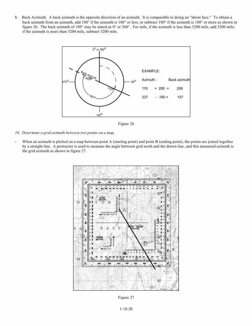
9. Determine a back azimuth.
a. An azimuth is defined as a horizontal angle measured clockwise from a north base line. This north base line could be true north,
magnetic north, or grid north. The azimuth is the most common military method to express direction. When using an azimuth,
the point from which the azimuth originates is the center of an imaginary circle as shown in figure 25. This circle is divided into
360° or 6400 mils.
Figure 25
1-18-20
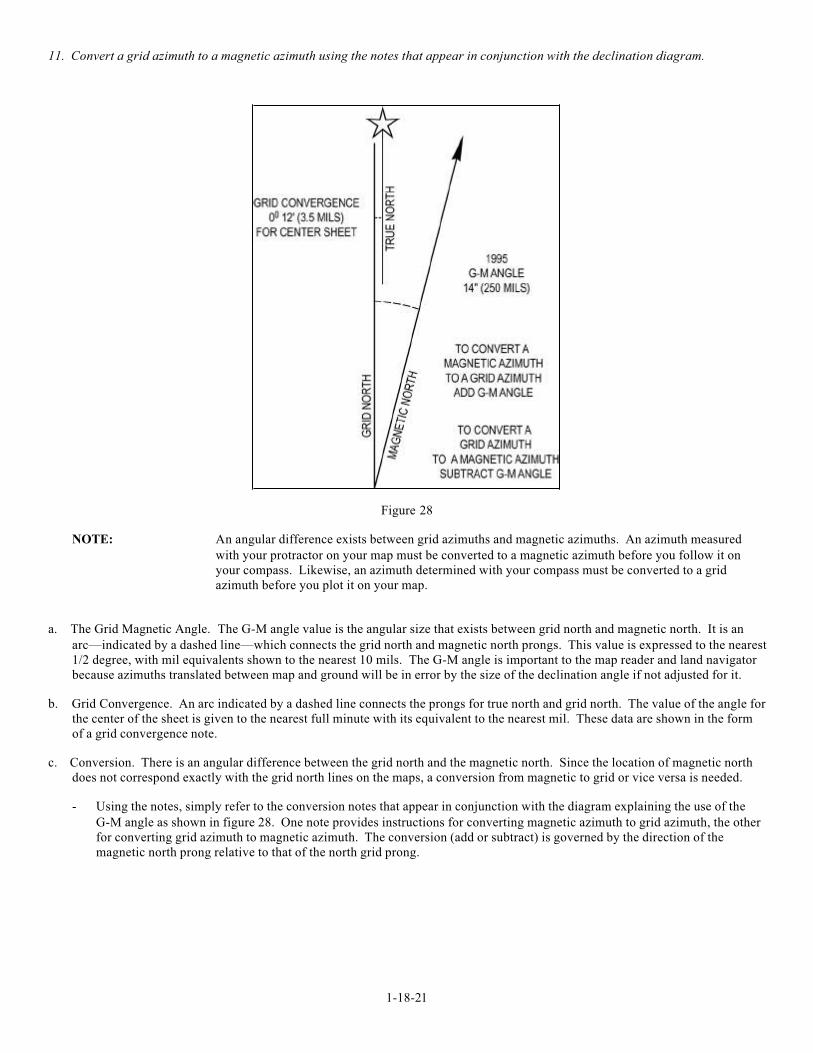
b. Back Azimuth. A back azimuth is the opposite direction of an azimuth. It is comparable to doing an "about face." To obtain a
back azimuth from an azimuth, add 180° if the azimuth is 180° or less; or subtract 180° if the azimuth is 180° or more as shown in
figure 26. The back azimuth of 180° may be stated as 0° or 360°. For mils, if the azimuth is less than 3200 mils, add 3200 mils;
if the azimuth is more than 3200 mils, subtract 3200 mils.
Figure 26
10. Determine a grid azimuth between two points on a map.
- When an azimuth is plotted on a map between point A (starting point) and point B (ending point), the points are joined together
by a straight line. A protractor is used to measure the angle between grid north and the drawn line, and this measured azimuth is
the grid azimuth as shown in figure 27.
Figure 27
1-18-21
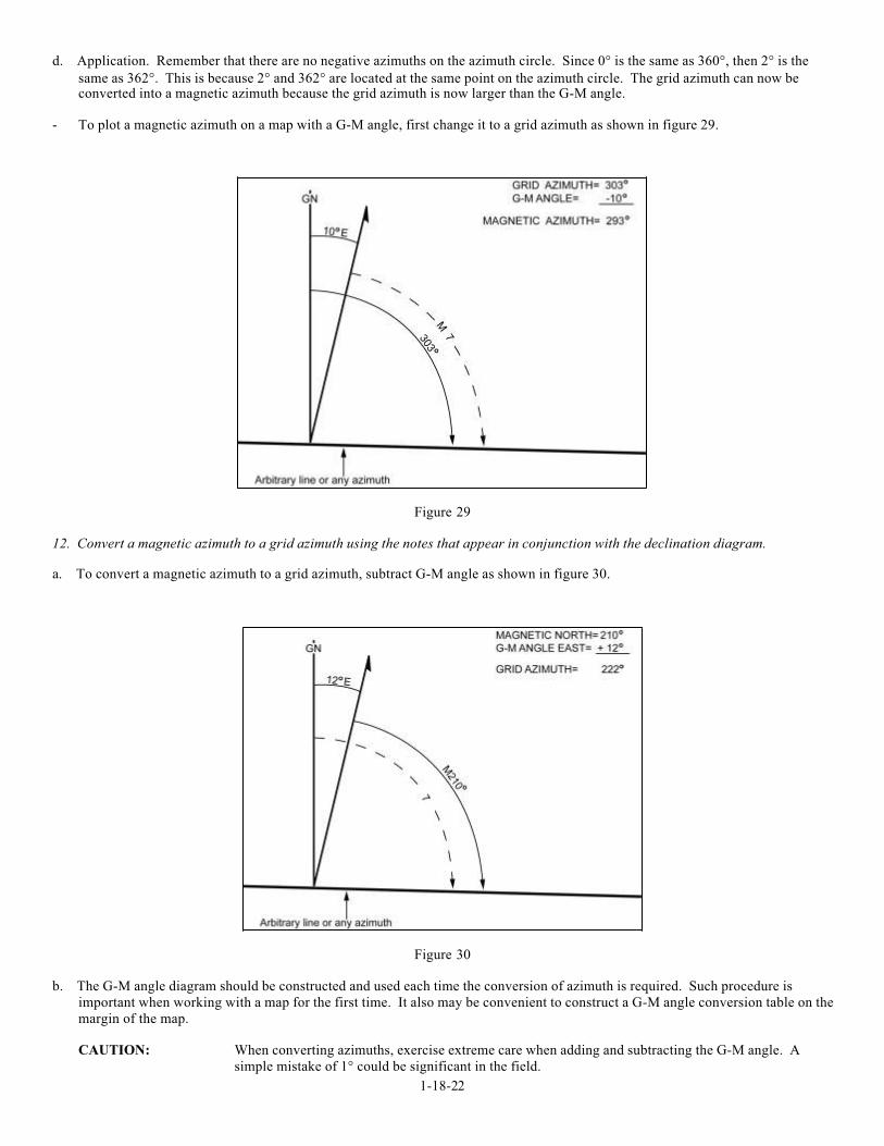
11. Convert a grid azimuth to a magnetic azimuth using the notes that appear in conjunction with the declination diagram.
Figure 28
NOTE: An angular difference exists between grid azimuths and magnetic azimuths. An azimuth measured
with your protractor on your map must be converted to a magnetic azimuth before you follow it on
your compass. Likewise, an azimuth determined with your compass must be converted to a grid
azimuth before you plot it on your map.
a. The Grid Magnetic Angle. The G-M angle value is the angular size that exists between grid north and magnetic north. It is an
arc—indicated by a dashed line—which connects the grid north and magnetic north prongs. This value is expressed to the nearest
1/2 degree, with mil equivalents shown to the nearest 10 mils. The G-M angle is important to the map reader and land navigator
because azimuths translated between map and ground will be in error by the size of the declination angle if not adjusted for it.
b. Grid Convergence. An arc indicated by a dashed line connects the prongs for true north and grid north. The value of the angle for
the center of the sheet is given to the nearest full minute with its equivalent to the nearest mil. These data are shown in the form
of a grid convergence note.
c. Conversion. There is an angular difference between the grid north and the magnetic north. Since the location of magnetic north
does not correspond exactly with the grid north lines on the maps, a conversion from magnetic to grid or vice versa is needed.
- Using the notes, simply refer to the conversion notes that appear in conjunction with the diagram explaining the use of the
G-M angle as shown in figure 28. One note provides instructions for converting magnetic azimuth to grid azimuth, the other
for converting grid azimuth to magnetic azimuth. The conversion (add or subtract) is governed by the direction of the
magnetic north prong relative to that of the north grid prong.
1-18-22
d. Application. Remember that there are no negative azimuths on the azimuth circle. Since 0° is the same as 360°, then 2° is the
same as 362°. This is because 2° and 362° are located at the same point on the azimuth circle. The grid azimuth can now beconverted into a magnetic azimuth because the grid azimuth is now larger than the G-M angle.
- To plot a magnetic azimuth on a map with a G-M angle, first change it to a grid azimuth as shown in figure 29.
Figure 29
12. Convert a magnetic azimuth to a grid azimuth using the notes that appear in conjunction with the declination diagram.
a. To convert a magnetic azimuth to a grid azimuth, subtract G-M angle as shown in figure 30.
Figure 30
b. The G-M angle diagram should be constructed and used each time the conversion of azimuth is required. Such procedure is
important when working with a map for the first time. It also may be convenient to construct a G-M angle conversion table on the
margin of the map.
CAUTION: When converting azimuths, exercise extreme care when adding and subtracting the G-M angle. A
simple mistake of 1° could be significant in the field.
1-18-23
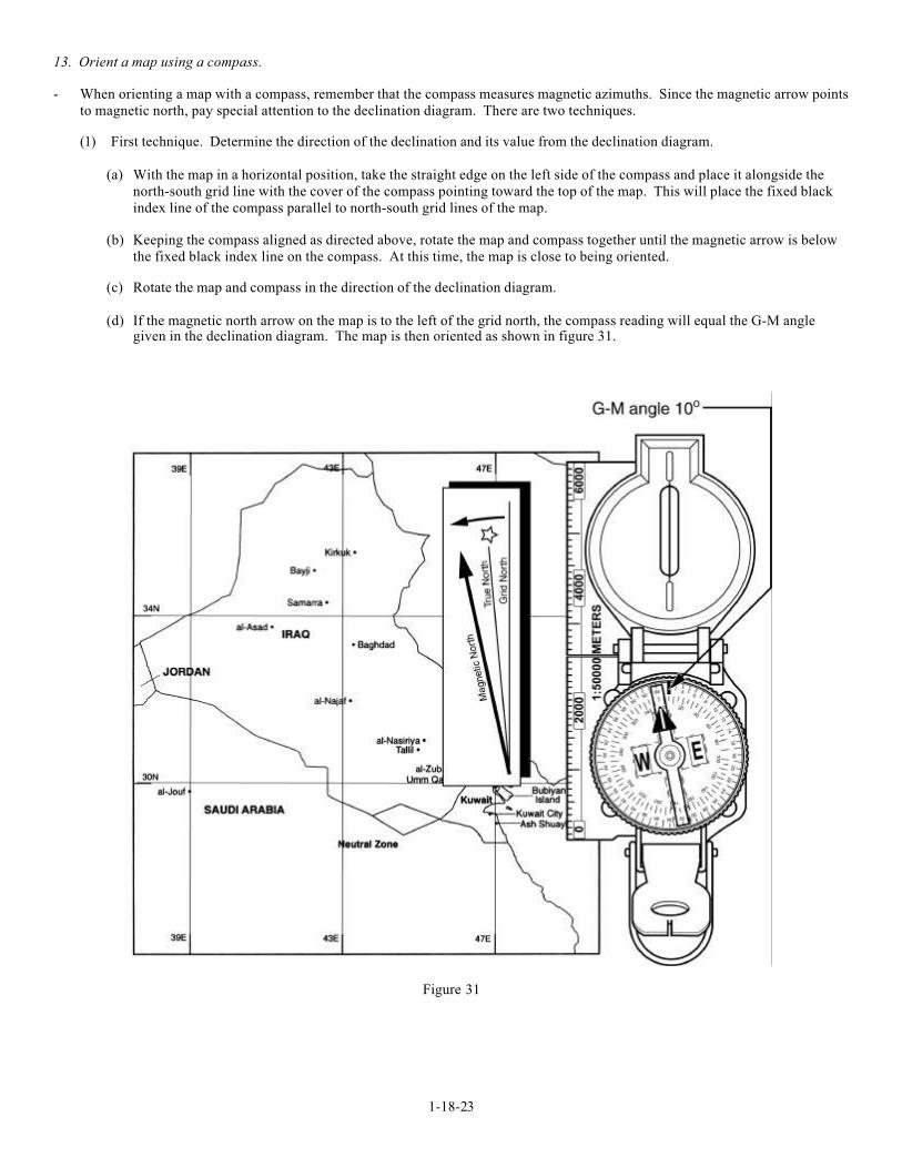
13. Orient a map using a compass.
- When orienting a map with a compass, remember that the compass measures magnetic azimuths. Since the magnetic arrow points
to magnetic north, pay special attention to the declination diagram. There are two techniques.
(1) First technique. Determine the direction of the declination and its value from the declination diagram.
(a) With the map in a horizontal position, take the straight edge on the left side of the compass and place it alongside the
north-south grid line with the cover of the compass pointing toward the top of the map. This will place the fixed black
index line of the compass parallel to north-south grid lines of the map.
(b) Keeping the compass aligned as directed above, rotate the map and compass together until the magnetic arrow is below
the fixed black index line on the compass. At this time, the map is close to being oriented.
(c) Rotate the map and compass in the direction of the declination diagram.
(d) If the magnetic north arrow on the map is to the left of the grid north, the compass reading will equal the G-M anglegiven in the declination diagram. The map is then oriented as shown in figure 31.
Figure 31
1-18-24
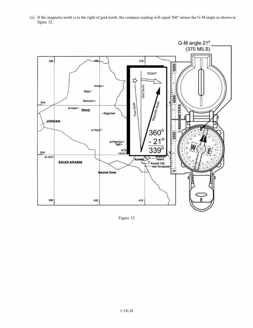
(e) If the magnetic north is to the right of grid north, the compass reading will equal 360° minus the G-M angle as shown in
figure 32.
Figure 32
1-18-25
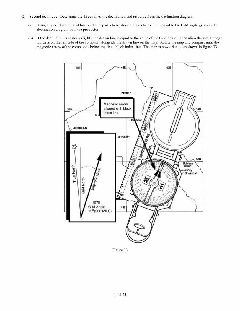
(2) Second technique. Determine the direction of the declination and its value from the declination diagram.
(a) Using any north-south grid line on the map as a base, draw a magnetic azimuth equal to the G-M angle given in the
declination diagram with the protractor.
(b) If the declination is easterly (right), the drawn line is equal to the value of the G-M angle. Then align the straightedge,
which is on the left side of the compass, alongside the drawn line on the map. Rotate the map and compass until the
magnetic arrow of the compass is below the fixed black index line. The map is now oriented as shown in figure 33.
Figure 33
1-18-26
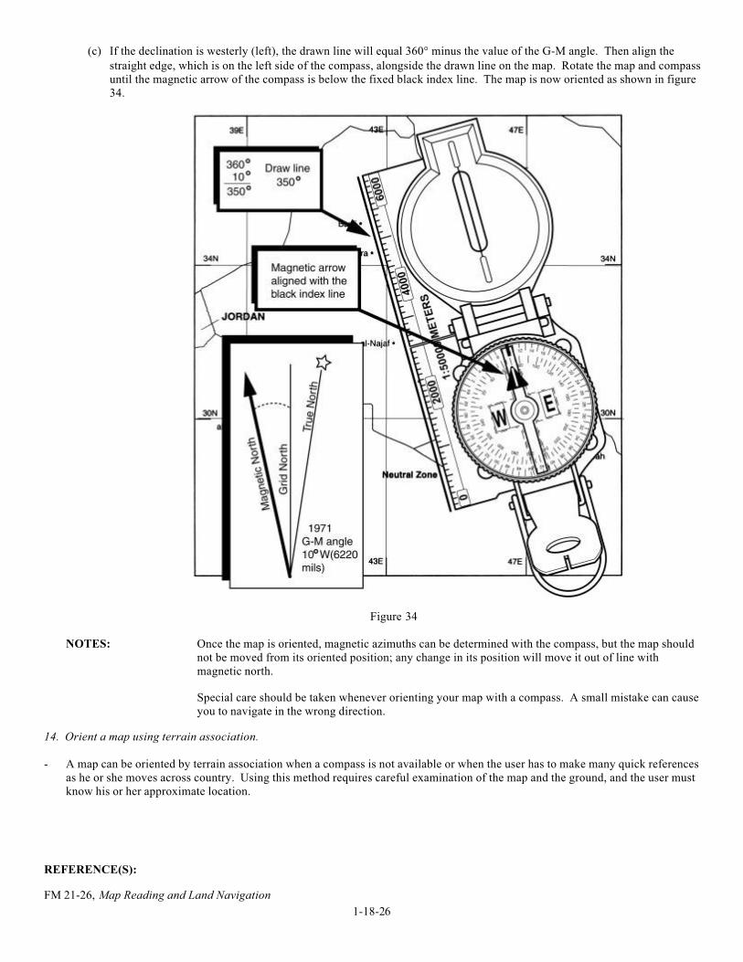
(c) If the declination is westerly (left), the drawn line will equal 360° minus the value of the G-M angle. Then align the
straight edge, which is on the left side of the compass, alongside the drawn line on the map. Rotate the map and compass
until the magnetic arrow of the compass is below the fixed black index line. The map is now oriented as shown in figure
34.
Figure 34
NOTES: Once the map is oriented, magnetic azimuths can be determined with the compass, but the map should
not be moved from its oriented position; any change in its position will move it out of line with
magnetic north.
Special care should be taken whenever orienting your map with a compass. A small mistake can cause
you to navigate in the wrong direction.
14. Orient a map using terrain association.
- A map can be oriented by terrain association when a compass is not available or when the user has to make many quick references
as he or she moves across country. Using this method requires careful examination of the map and the ground, and the user must
know his or her approximate location.
REFERENCE(S):
FM 21-26, Map Reading and Land Navigation
1-18-27
TASK: MCCS.18.04 (CORE) PERFORM LAND NAVIGATION WITH A MAP AND COMPASS
CONDITION: GIVEN THE REQUIREMENT.
STANDARD: TO DEMONSTRATE UNDERSTANDING PER THE REFERENCE.
EVALUATION GUIDELINES TO BE USED DURING TRAINING:
Condition: In a field environment during both day and night, the Marine is provided paper, a pen, a protractor, a lensatic
compass, a 1:50,000 military map, the six-digit grid coordinate of his current location, the six-digit grid
coordinates of and the magnetic azimuths to five checkpoints, and 782-gear.
Standard: The Marine must navigate to the five checkpoints, using a map and compass.
Administrative Notes: The land navigation route must have at least four separate direction changes, must be a total of
2400 meters in length during the day and 1200 meters in length during the night, and must have no
major obstacles (such as ponds, etc.) that the Marine must navigate around.
The Marine will not be permitted to use a flashlight after he begins the first leg of his night land
navigation course.
PERFORMANCE STEPS:
1. Determine daylight or darkness pace counts.
a. A pace is equal to one natural step, about 30 inches long. To accurately use the pace count method, you must know how many
paces it takes you to walk 100 meters. To determine this, you must walk an accurately measured course and count the number of
paces you take. A pace course can be as short as 100 meters or as long as 600 meters. The pace course, regardless of length,
must be on similar terrain to what you will be walking over. It does no good to walk a course on flat terrain and then try to use
that pace count on hilly terrain. To determine your pace count on a 600-meter course, count the paces it takes you to walk the 600
meters, then divide the total paces by 6. The answer will give you the average paces it takes you to walk 100 meters. It isimportant that each person who navigates while dismounted knows his pace count.
(1) There are many methods to keep track of the distance traveled when using the pace count. Some of these methods are put a
pebble in your pocket every time you have walked 100 meters according to your pace count; tie knots in a string; or put
marks in a notebook. Do not try to remember the count; always use one of these methods or design your own method.
(2) Certain conditions affect your pace count in the field, and you must allow for them by making adjustments.
(a) Slopes. Your pace will lengthen on a downslope and shorten on an upgrade. Keeping this in mind, if it normally takesyou 120 paces to walk 100 meters, your pace count may increase to 130 or more when walking up a slope.
(b) Winds. A head wind shortens the pace and a tail wind increases it.
(c) Surfaces. Sand, gravel, mud, snow, and similar surface materials tend to shorten the pace.
(d) Elements. Falling snow, rain, or ice causes the pace to be reduced in length.
(e) Clothing. Excess clothing and boots with poor traction affect the pace length.
(f) Visibility. Poor visibility, such as in fog, rain, or darkness, will shorten your pace.
b. The basic technique used for nighttime land navigation is dead reckoning with several compasses recommended. The point man
will be in front of the navigator but just a few steps away for easy control of the azimuth. Smaller steps are taken during night
navigation, so remember, the pace count will be different. It is recommended that a pace count obtained by using a predetermined100-meter pace course be used at night.
1-18-28
2. Perform basic map reading.
a. The six colors of a map and what each color represents.
(1) Black represents manmade features such as buildings, roads, trails, power lines, mines, and towers.
(2) Blue represents hydrographic or water features such as streams, rivers, ponds, lakes, swamps, and reservoirs.
(3) Green represents vegetation such as orchards, forests, and shrubs.
(4) Red represents major roads and other cultural features such as populated areas and boundaries.
(5) Brown represents contour lines.
(6) Red and brown are combined to identify cultural features, all relief features, non-surveyed spot elevations, and elevation,
such as contour lines on red-light readable maps.
NOTE: Newer maps have combined red and brown to the color identified as “red/brown.” This was done because
the color red did not show up well under a red lens flashlight. Therefore, the Marine may substitute
“red/brown” for red and brown; however, he must still identify what “"red/brown” represents, i.e., major
roads and contour lines.
b. Determine the six-digit grid coordinate of a specified point on a map.
NOTE: There is only one rule to remember when reading or reporting grid coordinates—always read to the RIGHT
and then UP.
(1) Determine the four-digit grid coordinate of a specified point on the map.
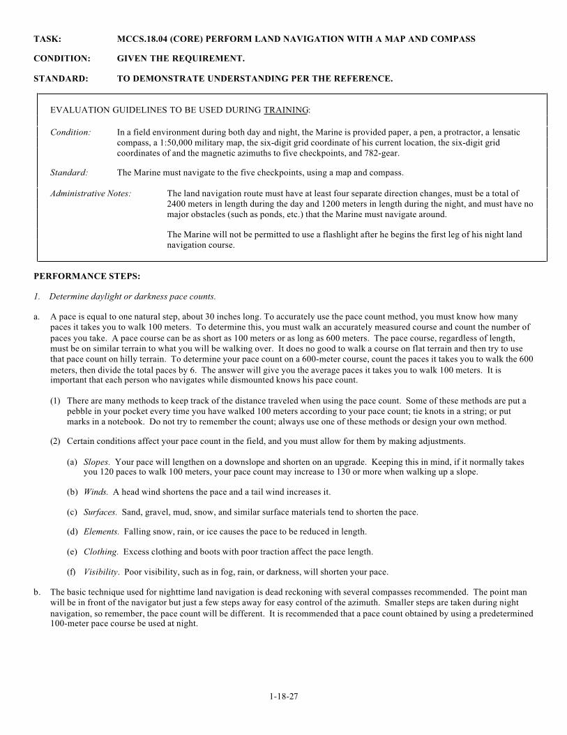
EXAMPLE: Let’s say that you desire to determine the grid coordinates of point C in figure 1 to the nearest 1,000
meters. First identify the grid square in which it is located. The cardinal rule of map reading is “READ
RIGHT, THEN UP.” In other words, looking at the numbers at the bottom of the map, read from left to
right until you identify the last north-south grid line before arriving at point C. This is grid line 30. Write
“30” on a piece of paper. Now look at the numbers on the side of the map and read UP until you identify
the last east-west grid line before arriving at point C. This is grid line 50. Write “50” beside the “30.” The
identity of the grid square is 3050. Note that the point where these two grid lines intersect is in the lower
left hand corner of the grid square. In other words, identify grid squares by the grid lines that intersect in
the lower left hand corner (figure 1).
Figure 1
1-18-29
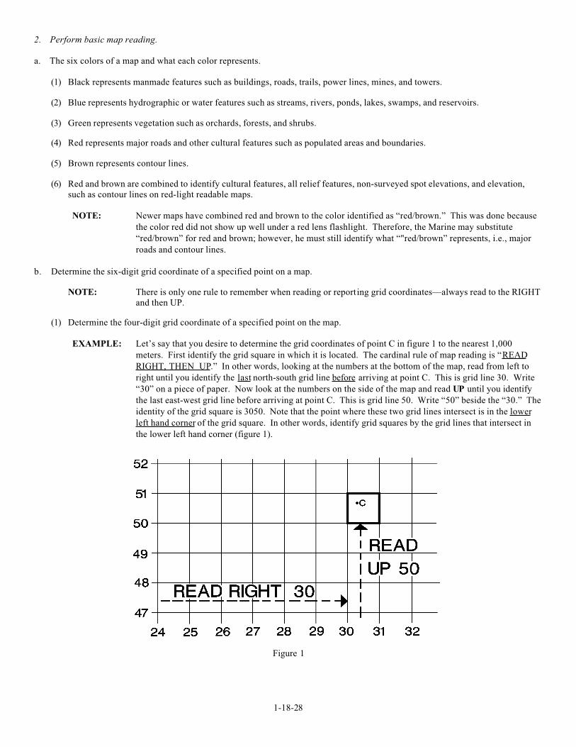
(2) Locate points within a grid square.
EXAMPLE: Imagine dividing the grid square into 100 smaller squares. The coordinates of a point in such a grid square
have six digits (numbers). Each of the grid squares in figure 2 is 1,000 meters wide and 1,000 meters high.
One of the grid squares is divided into 100 smaller squares, each 100 meters wide and 100 meters high.
Note that the lines within the grid square also read “RIGHT, THEN UP.” In a six-digit grid coordinate,
such as 303507, the first 3 numbers (303) are the “READ RIGHT” part; whereas, the last 3 numbers (507)
are the “THEN UP” part.
Figure 2
NOTE: The standard GTA 5-2-12 1981 protractor has three coordinate scales, one for 1:50,000 maps, one for
1:100,000 maps, and one for either 1:25,000 or 1:250,000 maps. Use the scale that fits your map. In this
case, it should be the 1:50,000 scale that is in the upper left hand corner of the protractor.
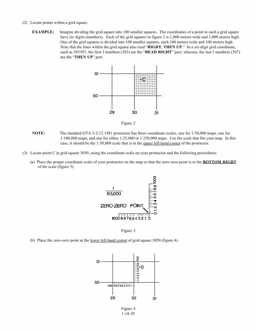
(3) Locate point C in grid square 3050, using the coordinate scale on your protractor and the following procedures:
(a) Place the proper coordinate scale of your protractor on the map so that the zero-zero point is to the BOTTOM RIGHT
of the scale (figure 3).
Figure 3
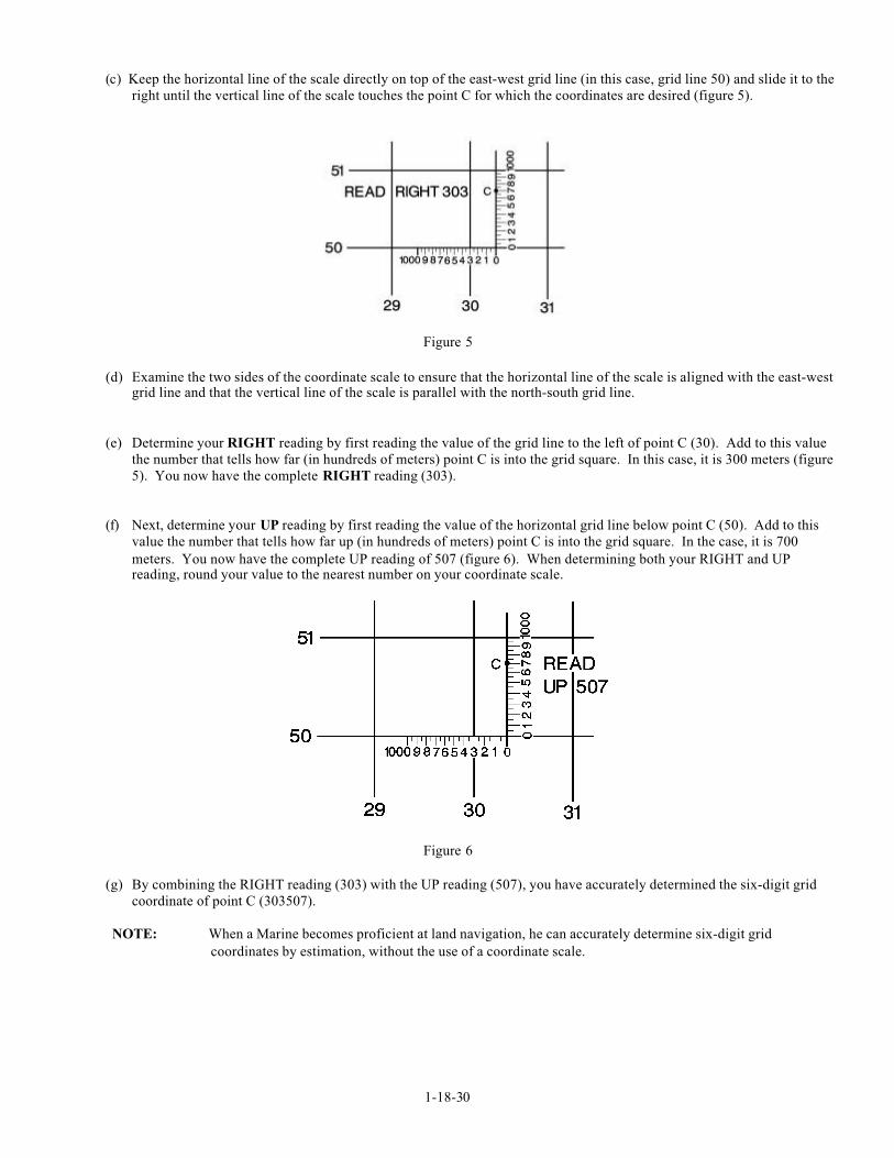
(b) Place the zero-zero point at the lower left hand corner of grid square 3050 (figure 4).
Figure 4
1-18-30
(c) Keep the horizontal line of the scale directly on top of the east-west grid line (in this case, grid line 50) and slide it to the
right until the vertical line of the scale touches the point C for which the coordinates are desired (figure 5).
Figure 5
(d) Examine the two sides of the coordinate scale to ensure that the horizontal line of the scale is aligned with the east-westgrid line and that the vertical line of the scale is parallel with the north-south grid line.
(e) Determine your RIGHT reading by first reading the value of the grid line to the left of point C (30). Add to this value
the number that tells how far (in hundreds of meters) point C is into the grid square. In this case, it is 300 meters (figure
5). You now have the complete RIGHT reading (303).
(f) Next, determine your UP reading by first reading the value of the horizontal grid line below point C (50). Add to this
value the number that tells how far up (in hundreds of meters) point C is into the grid square. In the case, it is 700
meters. You now have the complete UP reading of 507 (figure 6). When determining both your RIGHT and UPreading, round your value to the nearest number on your coordinate scale.
Figure 6
(g) By combining the RIGHT reading (303) with the UP reading (507), you have accurately determined the six-digit grid
coordinate of point C (303507).
NOTE: When a Marine becomes proficient at land navigation, he can accurately determine six-digit grid
coordinates by estimation, without the use of a coordinate scale.
1-18-31
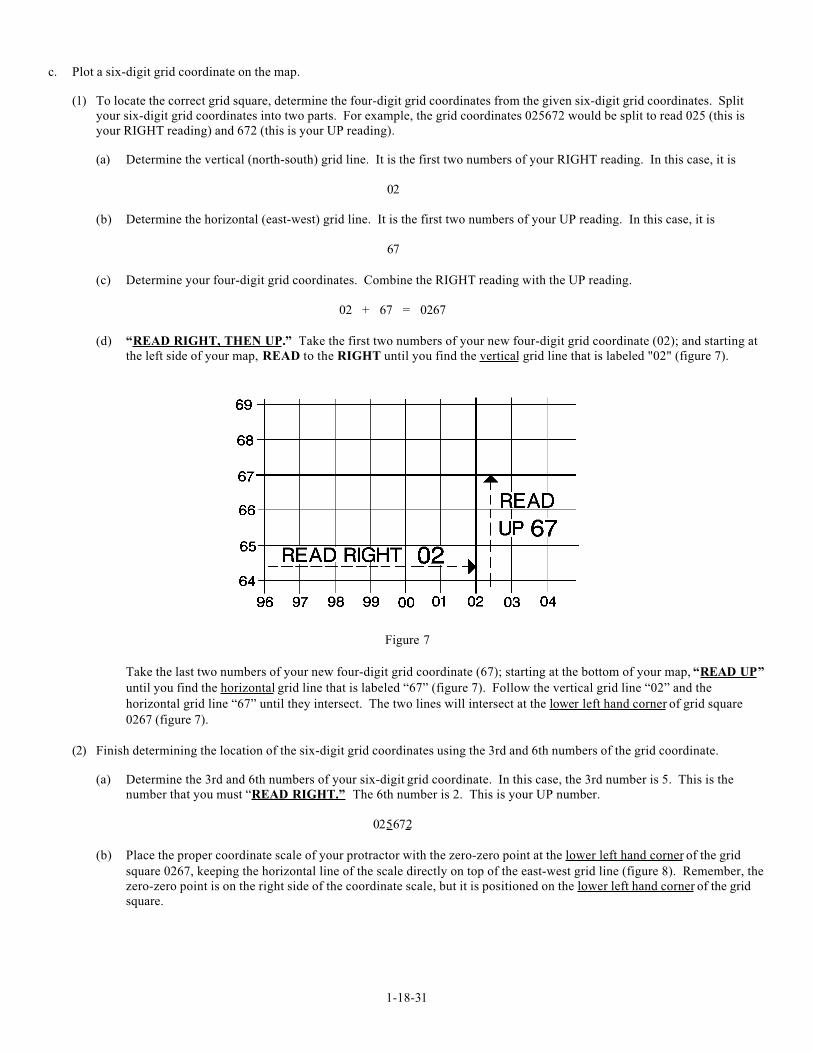
c. Plot a six-digit grid coordinate on the map.
(1) To locate the correct grid square, determine the four-digit grid coordinates from the given six-digit grid coordinates. Split
your six-digit grid coordinates into two parts. For example, the grid coordinates 025672 would be split to read 025 (this is
your RIGHT reading) and 672 (this is your UP reading).
(a) Determine the vertical (north-south) grid line. It is the first two numbers of your RIGHT reading. In this case, it is
02
(b) Determine the horizontal (east-west) grid line. It is the first two numbers of your UP reading. In this case, it is
67
(c) Determine your four-digit grid coordinates. Combine the RIGHT reading with the UP reading.
02 + 67 = 0267
(d) “READ RIGHT, THEN UP.” Take the first two numbers of your new four-digit grid coordinate (02); and starting at
the left side of your map, READ to the RIGHT until you find the vertical grid line that is labeled "02" (figure 7).
Figure 7
Take the last two numbers of your new four-digit grid coordinate (67); starting at the bottom of your map, “READ UP”
until you find the horizontal grid line that is labeled “67” (figure 7). Follow the vertical grid line “02” and the
horizontal grid line “67” until they intersect. The two lines will intersect at the lower left hand corner of grid square
0267 (figure 7).
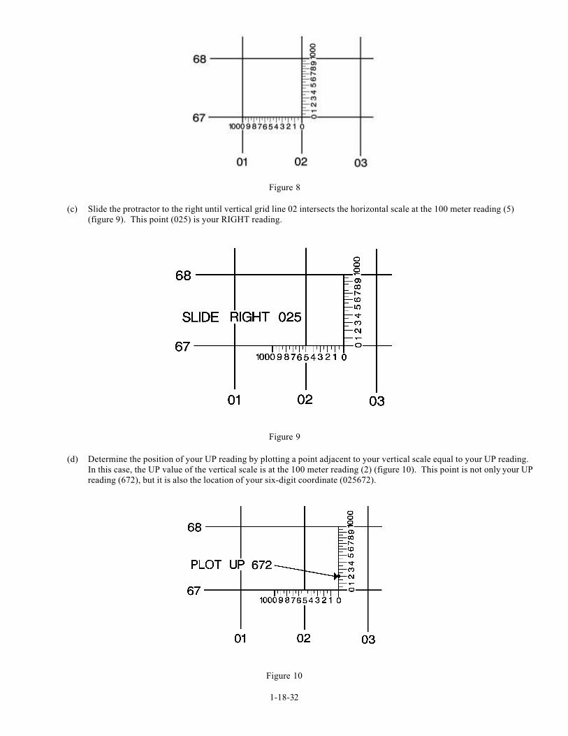
(2) Finish determining the location of the six-digit grid coordinates using the 3rd and 6th numbers of the grid coordinate.
(a) Determine the 3rd and 6th numbers of your six-digit grid coordinate. In this case, the 3rd number is 5. This is the
number that you must “READ RIGHT.” The 6th number is 2. This is your UP number.
025672
(b) Place the proper coordinate scale of your protractor with the zero-zero point at the lower left hand corner of the grid
square 0267, keeping the horizontal line of the scale directly on top of the east-west grid line (figure 8). Remember, the
zero-zero point is on the right side of the coordinate scale, but it is positioned on the lower left hand corner of the grid
square.
1-18-32
Figure 8
(c) Slide the protractor to the right until vertical grid line 02 intersects the horizontal scale at the 100 meter reading (5)
(figure 9). This point (025) is your RIGHT reading.
Figure 9
(d) Determine the position of your UP reading by plotting a point adjacent to your vertical scale equal to your UP reading.
In this case, the UP value of the vertical scale is at the 100 meter reading (2) (figure 10). This point is not only your UP
reading (672), but it is also the location of your six-digit coordinate (025672).
Figure 10
1-18-33
d. Identify natural features on a map.
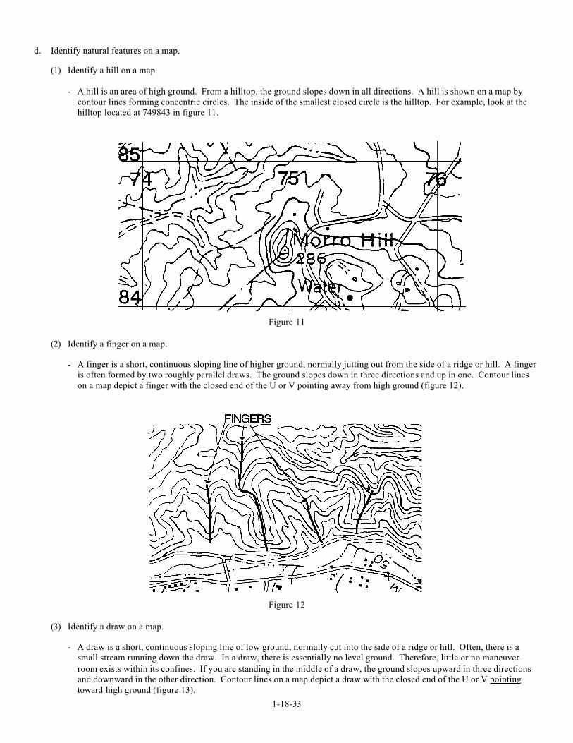
(1) Identify a hill on a map.
- A hill is an area of high ground. From a hilltop, the ground slopes down in all directions. A hill is shown on a map by
contour lines forming concentric circles. The inside of the smallest closed circle is the hilltop. For example, look at the
hilltop located at 749843 in figure 11.
Figure 11
(2) Identify a finger on a map.
- A finger is a short, continuous sloping line of higher ground, normally jutting out from the side of a ridge or hill. A finger
is often formed by two roughly parallel draws. The ground slopes down in three directions and up in one. Contour lines
on a map depict a finger with the closed end of the U or V pointing away from high ground (figure 12).
Figure 12
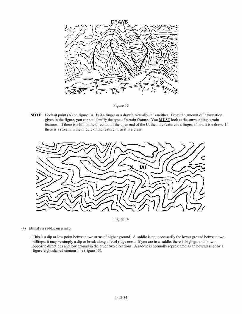
(3) Identify a draw on a map.
- A draw is a short, continuous sloping line of low ground, normally cut into the side of a ridge or hill. Often, there is a
small stream running down the draw. In a draw, there is essentially no level ground. Therefore, little or no maneuver
room exists within its confines. If you are standing in the middle of a draw, the ground slopes upward in three directions
and downward in the other direction. Contour lines on a map depict a draw with the closed end of the U or V pointing
toward high ground (figure 13).
1-18-34
Figure 13
NOTE: Look at point (A) on figure 14. Is it a finger or a draw? Actually, it is neither. From the amount of information
given in the figure, you cannot identify the type of terrain feature. You MUST look at the surrounding terrain
features. If there is a hill in the direction of the open end of the U, then the feature is a finger; if not, it is a draw. If
there is a stream in the middle of the feature, then it is a draw.
Figure 14
(4) Identify a saddle on a map.
- This is a dip or low point between two areas of higher ground. A saddle is not necessarily the lower ground between two
hilltops; it may be simply a dip or break along a level ridge crest. If you are in a saddle, there is high ground in two
opposite directions and low ground in the other two directions. A saddle is normally represented as an hourglass or by a
figure-eight shaped contour line (figure 15).
1-18-35
Figure 15
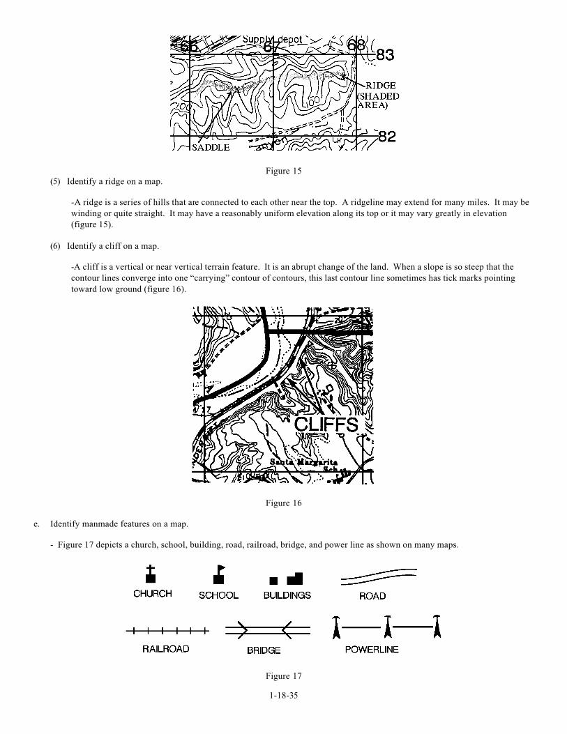
(5) Identify a ridge on a map.
-A ridge is a series of hills that are connected to each other near the top. A ridgeline may extend for many miles. It may be
winding or quite straight. It may have a reasonably uniform elevation along its top or it may vary greatly in elevation
(figure 15).
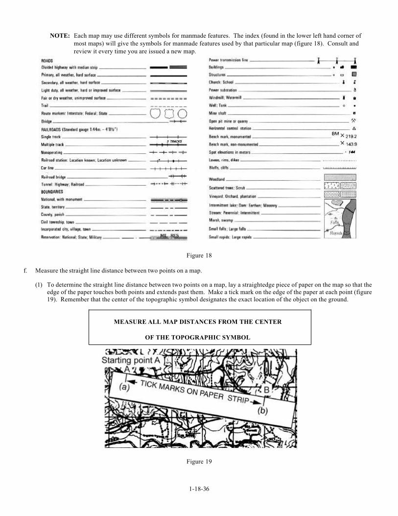
(6) Identify a cliff on a map.
-A cliff is a vertical or near vertical terrain feature. It is an abrupt change of the land. When a slope is so steep that the
contour lines converge into one “carrying” contour of contours, this last contour line sometimes has tick marks pointing
toward low ground (figure 16).
Figure 16
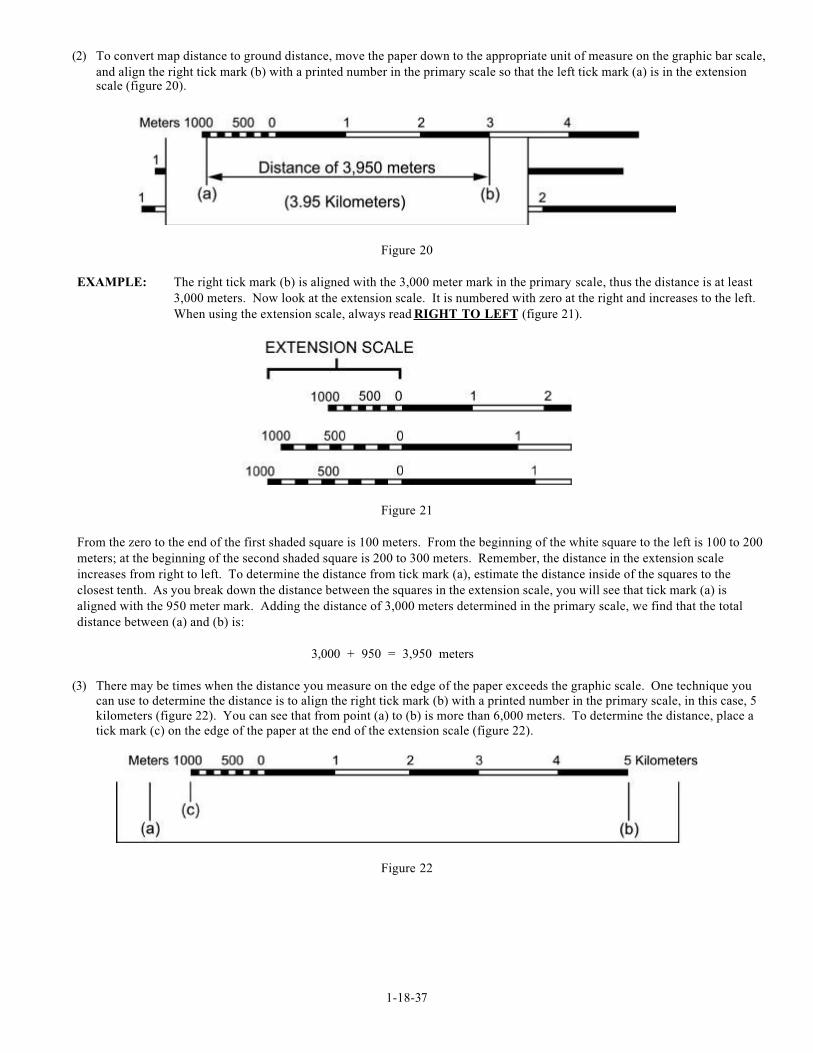
e. Identify manmade features on a map.
- Figure 17 depicts a church, school, building, road, railroad, bridge, and power line as shown on many maps.
Figure 17
1-18-36
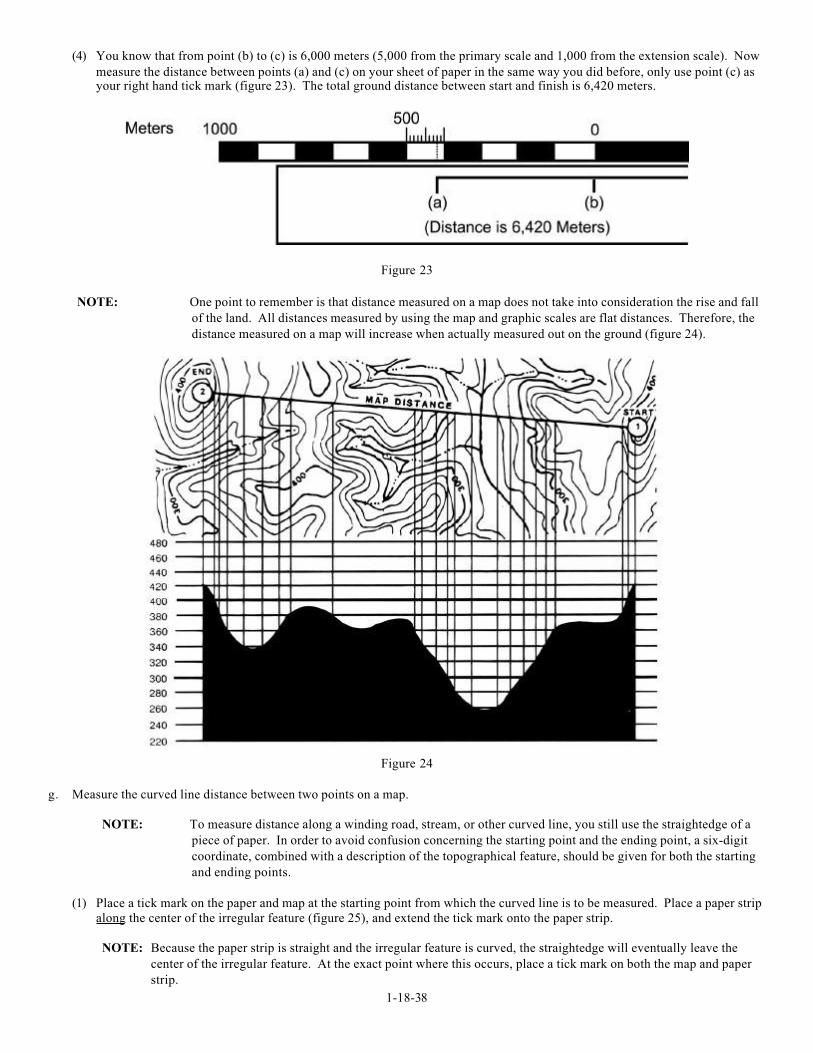
NOTE: Each map may use different symbols for manmade features. The index (found in the lower left hand corner of
most maps) will give the symbols for manmade features used by that particular map (figure 18). Consult and
review it every time you are issued a new map.
Figure 18
f. Measure the straight line distance between two points on a map.
(1) To determine the straight line distance between two points on a map, lay a straightedge piece of paper on the map so that the
edge of the paper touches both points and extends past them. Make a tick mark on the edge of the paper at each point (figure
19). Remember that the center of the topographic symbol designates the exact location of the object on the ground.
MEASURE ALL MAP DISTANCES FROM THE CENTER
OF THE TOPOGRAPHIC SYMBOL
Figure 19
1-18-37
(2) To convert map distance to ground distance, move the paper down to the appropriate unit of measure on the graphic bar scale,
and align the right tick mark (b) with a printed number in the primary scale so that the left tick mark (a) is in the extensionscale (figure 20).
Figure 20
EXAMPLE: The right tick mark (b) is aligned with the 3,000 meter mark in the primary scale, thus the distance is at least
3,000 meters. Now look at the extension scale. It is numbered with zero at the right and increases to the left.
When using the extension scale, always read RIGHT TO LEFT (figure 21).
Figure 21
From the zero to the end of the first shaded square is 100 meters. From the beginning of the white square to the left is 100 to 200
meters; at the beginning of the second shaded square is 200 to 300 meters. Remember, the distance in the extension scale
increases from right to left. To determine the distance from tick mark (a), estimate the distance inside of the squares to the
closest tenth. As you break down the distance between the squares in the extension scale, you will see that tick mark (a) is
aligned with the 950 meter mark. Adding the distance of 3,000 meters determined in the primary scale, we find that the total
distance between (a) and (b) is:
3,000 + 950 = 3,950 meters
(3) There may be times when the distance you measure on the edge of the paper exceeds the graphic scale. One technique you
can use to determine the distance is to align the right tick mark (b) with a printed number in the primary scale, in this case, 5
kilometers (figure 22). You can see that from point (a) to (b) is more than 6,000 meters. To determine the distance, place a
tick mark (c) on the edge of the paper at the end of the extension scale (figure 22).
Figure 22
1-18-38
(4) You know that from point (b) to (c) is 6,000 meters (5,000 from the primary scale and 1,000 from the extension scale). Now
measure the distance between points (a) and (c) on your sheet of paper in the same way you did before, only use point (c) asyour right hand tick mark (figure 23). The total ground distance between start and finish is 6,420 meters.
Figure 23
NOTE: One point to remember is that distance measured on a map does not take into consideration the rise and fall
of the land. All distances measured by using the map and graphic scales are flat distances. Therefore, the
distance measured on a map will increase when actually measured out on the ground (figure 24).
Figure 24
g. Measure the curved line distance between two points on a map.
NOTE: To measure distance along a winding road, stream, or other curved line, you still use the straightedge of a
piece of paper. In order to avoid confusion concerning the starting point and the ending point, a six-digit
coordinate, combined with a description of the topographical feature, should be given for both the starting
and ending points.
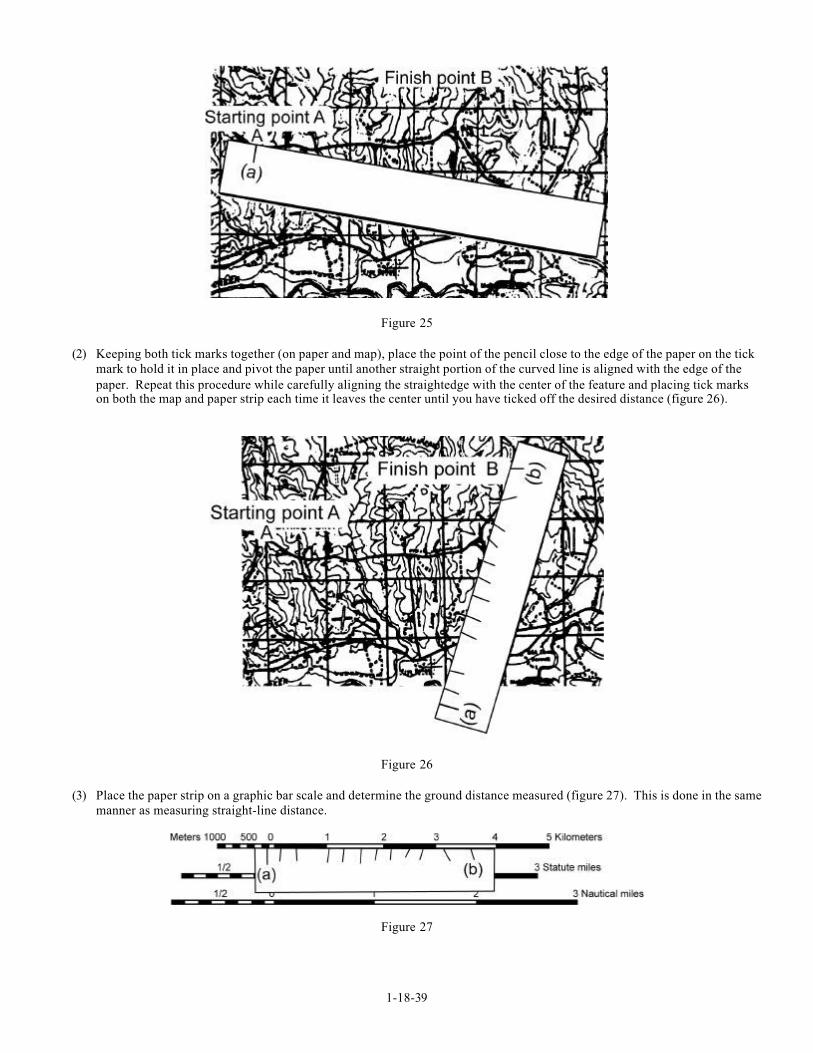
(1) Place a tick mark on the paper and map at the starting point from which the curved line is to be measured. Place a paper strip
along the center of the irregular feature (figure 25), and extend the tick mark onto the paper strip.
NOTE: Because the paper strip is straight and the irregular feature is curved, the straightedge will eventually leave the
center of the irregular feature. At the exact point where this occurs, place a tick mark on both the map and paper
strip.
1-18-39
Figure 25
(2) Keeping both tick marks together (on paper and map), place the point of the pencil close to the edge of the paper on the tick
mark to hold it in place and pivot the paper until another straight portion of the curved line is aligned with the edge of the
paper. Repeat this procedure while carefully aligning the straightedge with the center of the feature and placing tick markson both the map and paper strip each time it leaves the center until you have ticked off the desired distance (figure 26).
Figure 26
(3) Place the paper strip on a graphic bar scale and determine the ground distance measured (figure 27). This is done in the same
manner as measuring straight-line distance.
Figure 27

1-18-40
3. Follow an azimuth using the center-hold technique.
- First, open the compass to its fullest so that the cover forms a straightedge with the base. Move the lens (rear sight) to the rearmost
position, allowing the dial to float freely. Next, place your thumb through the thumb loop, form a steady base with your third and
fourth fingers, and extend your index finger along the side of the compass. Place the thumb of the other hand between the lens
(rear sight) and the bezel ring; extend the index finger along the remaining side of the compass and the remaining fingers around
the fingers of the other hand. Pull your elbows firmly into your sides; this will place the compass between your chin and your belt.
To measure an azimuth, simply turn your entire body toward the object, pointing the compass cover directly at the object. Once
you are pointing at the object, look down and read the azimuth from beneath the fixed black index line (figure 28). This preferred
method offers the following advantages over the sighting technique. It can be used
(1) Faster and easier
(2) Under all conditions of visibility
(3) When navigating over any type of terrain
(4) Without putting down the rifle; however, the rifle must he slung well back over either shoulder
(5) Without removing eyeglasses
Figure 28
1-18-41
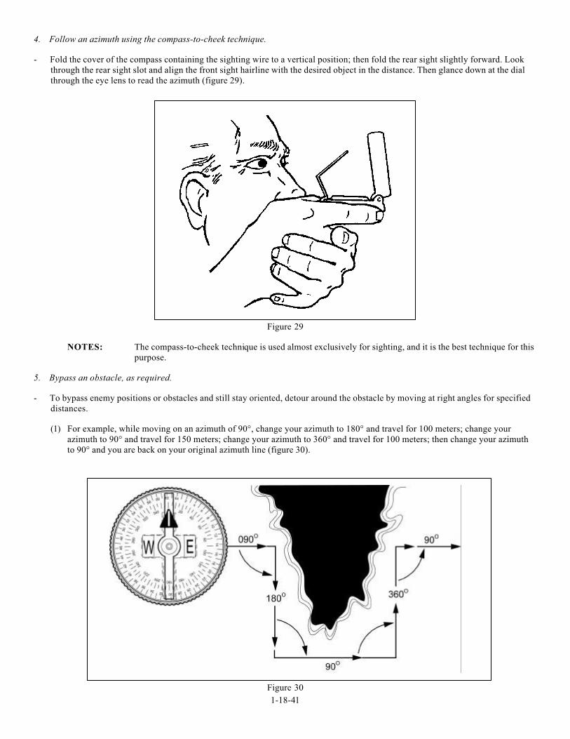
4. Follow an azimuth using the compass-to-cheek technique.
- Fold the cover of the compass containing the sighting wire to a vertical position; then fold the rear sight slightly forward. Look
through the rear sight slot and align the front sight hairline with the desired object in the distance. Then glance down at the dial
through the eye lens to read the azimuth (figure 29).
Figure 29
NOTES: The compass-to-cheek technique is used almost exclusively for sighting, and it is the best technique for this
purpose.
5. Bypass an obstacle, as required.
- To bypass enemy positions or obstacles and still stay oriented, detour around the obstacle by moving at right angles for specified
distances.
(1) For example, while moving on an azimuth of 90°, change your azimuth to 180° and travel for 100 meters; change your
azimuth to 90° and travel for 150 meters; change your azimuth to 360° and travel for 100 meters; then change your azimuth
to 90° and you are back on your original azimuth line (figure 30).
Figure 30
1-18-42
(2) Bypassing an unexpected obstacle at night is a simple matter. To make a 90° turn to the right, hold the compass in the center
hold technique; turn until the center of the luminous letter E is under the luminous line (do not move the bezel ring). To make
a 90° turn to the left, turn until the center of the luminous letter W is under the luminous line. This does not require changing
the compass setting (bezel ring), and it ensures accurate 90° turns.
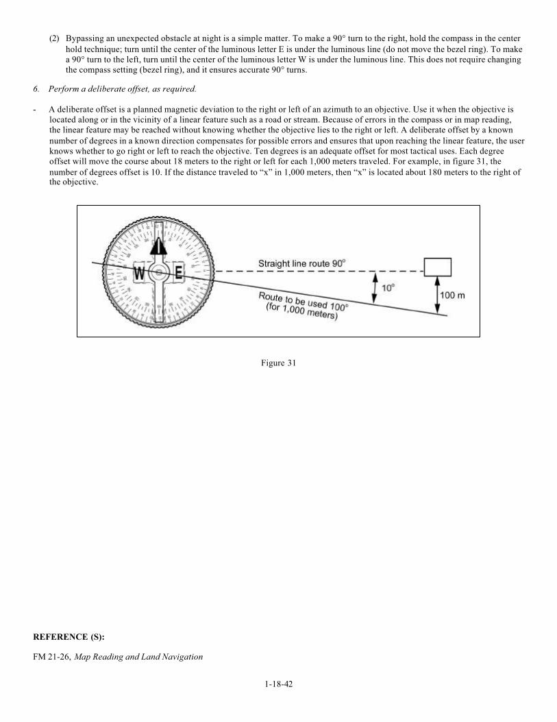
6. Perform a deliberate offset, as required.
- A deliberate offset is a planned magnetic deviation to the right or left of an azimuth to an objective. Use it when the objective is
located along or in the vicinity of a linear feature such as a road or stream. Because of errors in the compass or in map reading,
the linear feature may be reached without knowing whether the objective lies to the right or left. A deliberate offset by a known
number of degrees in a known direction compensates for possible errors and ensures that upon reaching the linear feature, the user
knows whether to go right or left to reach the objective. Ten degrees is an adequate offset for most tactical uses. Each degree
offset will move the course about 18 meters to the right or left for each 1,000 meters traveled. For example, in figure 31, the
number of degrees offset is 10. If the distance traveled to “x” in 1,000 meters, then “x” is located about 180 meters to the right ofthe objective.
Figure 31
REFERENCE (S):
FM 21-26, Map Reading and Land Navigation