tactics, techniques, and procedures (ttps) for the joint network
TRANSCRIPT

FMI 6-02.60
Tactics, Techniques, and Procedures (TTPs) for the Joint Network Node-Network (JNN-N)
SEPTEMBER 2006 Expires SEPTEMBER 2008
DISTRIBUTION RESTRICTION. Approved for public release; distribution is unlimited.
Headquarters, Department of the Army

FMI 6-02.60
Distribution Restriction: Approved for public release; distribution is unlimited.
i
Field Manual Interim No. 6-02.60
Headquarters Department of the Army
Washington, DC, 5 September 2006 Expires 5 September 2008
Tactics, Techniques, and Procedures (TTPs) for the Joint Network Node-Network (J-NN-N)
Contents Page
PREFACE...............................................................................................................v Chapter 1 THE JOINT NETWORK TRANSPORT CAPABILITIES - SPIRAL................... 1-1
Joint Network Transport Capabilities - Spiral ..................................................... 1-2 Chapter 2 JOINT NETWORK NODE-NETWORK .............................................................. 2-1
Network Description ........................................................................................... 2-1 Transmission Capabilities................................................................................... 2-3 Connectivity to Current Networks....................................................................... 2-8
Chapter 3 EMPLOYMENT OF THE JOINT NETWORK NODE-NETWORK AT THE DIVISION, BRIGADE, AND BATTALION LEVEL............................................. 3-1 Division ............................................................................................................... 3-1 Brigade Combat Teams...................................................................................... 3-3 Battalion.............................................................................................................. 3-5
Chapter 4 JOINT NETWORK NODE-NETWORK NETWORK MANAGEMENT............... 4-1 Network Management Components................................................................... 4-1 Network Management at the Division................................................................. 4-2 Network Management at the Brigade................................................................. 4-3 Network Management at the Battalion ............................................................... 4-3
Appendix A UNIT HUB NODE COMPONENT LISTING .......................................................A-1 Baseband Shelter ...............................................................................................A-2 Satellite Vans......................................................................................................A-6
Appendix B JOINT NETWORK NODE COMPONENTS AND CONNECTIVITY ..................B-1 Components .......................................................................................................B-2 Patch Panels ......................................................................................................B-3 Non-Secure Data Network..................................................................................B-4 Secure Internet Protocol Data Network............................................................B-28 Voice Switching ................................................................................................B-48 Signal Entry Panels ..........................................................................................B-58 Satellite Transportable Terminal ......................................................................B-61 Transit Cases ...................................................................................................B-61 Maintenance .....................................................................................................B-61

Contents
ii FMI 6-02.60 5 September 2006
Appendix C COMMAND POST NODE COMPONENT LISTING, STARTUP, AND MAINTENANCE PROCEDURES ......................................................................C-1 Division and Brigade Interface Cases ................................................................C-1 Battalion Command Post Node System Components .......................................C-7 Configuring the Battalion Router Case.............................................................C-15 Command Post Node Transit Case Maintenenance........................................C-23
Appendix D KU BAND SATELLITE TRANSPORTABLE TERMINAL .................................D-1 Capabilities .........................................................................................................D-1 Ku Band Satellite Transportable Terminal Equipment Description ....................D-3 Equipment Power Up..........................................................................................D-6
GLOSSARY ..........................................................................................Glossary-1 REFERENCES ..................................................................................References-1 INDEX.......................................................................................................... Index-1
Figures Figure 1-1. JNN Network at Division and Below ....................................................................1-1 Figure 1-2. JNTC-S Support for CSS .....................................................................................1-3 Figure 1-3. JNTC-S Military Intelligence Support ...................................................................1-4 Figure 2-1. JNN and Associated Equipment ..........................................................................2-3 Figure 2-2. Ku Band Satellite Terminal Connection via SEP MP3.........................................2-5 Figure 2-3. GMF Satellite Terminal Connection via SEP MP3...............................................2-6 Figure 2-4. SMART-T Terminal Connection via SEP MP1 ....................................................2-6 Figure 2-5. HCLOS (V1) and (V3) Terminal Connection via SEP MP 2 ................................2-7 Figure 2-6. Over-the-Air Communications Links ....................................................................2-8 Figure 3-1. Division to BCT Connectivity................................................................................3-3 Figure 3-2. Representative CP Configuration ........................................................................3-4 Figure 3-3. Battalion Command Post Connectivity.................................................................3-5 Figure A-1. Division Network Satellite Systems Overview .....................................................A-1 Figure A-2. Baseband and Satellite Vans Interconnections...................................................A-2 Figure B-1. JNN and BCT Deployment ..................................................................................B-1 Figure B-2. JNN Roadside View.............................................................................................B-2 Figure B-3. JNN Curbside View..............................................................................................B-3 Figure B-4. Information Assurance-based Architecture .........................................................B-4 Figure B-5. NIPRNET Data Network ......................................................................................B-5 Figure B-6. SIPRNET Data Network ................................................................................... B-29 Figure B-7. Secure Virtual Network with TACLANEs.......................................................... B-46 Figure B-8. JNN NIPRNET Voice Diagram ......................................................................... B-49 Figure B-9. JNN SIPRNET Voice Diagram ......................................................................... B-50 Figure B-10. Voice Connectivity to MSE and TRI-TAC Networks....................................... B-53 Figure B-11. TRC Block Diagram........................................................................................ B-56 Figure B-12. Signal Flow Using KIV-7................................................................................. B-57

Contents
5 September 2006 FMI 6-02.60 iii
Figure B-13. Typical KIV-19 Application.............................................................................. B-58 Figure B-14. Cable Connections for MP1............................................................................ B-59 Figure B-15. Cable Connections for MP2............................................................................ B-60 Figure B-16. Cable Connections for MP3............................................................................ B-60 Figure C-1. SIPRNET and NIPRNET Domains..................................................................... C-2 Figure C-2. Connection between JNN and Interface Cases ................................................. C-5 Figure C-3. Red and Black Voice Telephony Case............................................................... C-6 Figure C-4. Battalion Command Post Node Block Diagram ................................................. C-8 Figure C-5. LOS Block Diagram.......................................................................................... C-11 Figure C-6. Network Diagram of CPN Transit Cases and JNN........................................... C-13 Figure D-1. Equipment Racks ............................................................................................... D-2 Figure D-2. Satellite Transportable Terminal Trailer ............................................................. D-3 Figure D-3. Block Diagram .................................................................................................... D-7
Tables Table 3-1. Network Hub Platoon ............................................................................................3-1 Table 3-2. Joint Network Node Section..................................................................................3-4 Table 3-3. Command Post Support Section...........................................................................3-5 Table B-1. Configure a Tier 1 Router .....................................................................................B-6 Table B-2. Representative Entries for Tier 1 Router Configuration........................................B-6 Table B-3. Configure a Tier 2 Router .................................................................................. B-11 Table B-4. Representative Entries for Tier 2 Router Configuration..................................... B-12 Table B-5. Configure a VPN Router .................................................................................... B-18 Table B-6. Representative Entries for a VPN Router Configuration ................................... B-19 Table B-7. Connecting and Configuring Firewall................................................................. B-24 Table B-8. Set IP Address ................................................................................................... B-25 Table B-9. Connect Using TELNET .................................................................................... B-25 Table B-10. Connect Using WebUI ..................................................................................... B-25 Table B-11. Representative Entries for a JNN Firewall Configuration ................................ B-25 Table B-12. Representative Entries for a SIPRNET Tier 1 Router Configuration............... B-29 Table B-13. Representative Entries for a SIPRNET Tier 2 Router Configuration............... B-36 Table B-14. Configuring the TACLANE............................................................................... B-46 Table B-15. Configuring the Call Manager .......................................................................... B-50 Table B-16. Vantage Start up and Configuration ................................................................ B-53 Table C-1. SIPRNET Connection Points............................................................................... C-4 Table C-2. NIPRNET Connection Points............................................................................... C-4 Table C-3. CPN Router Case Connection Points................................................................ C-14 Table C-4. Sample Configuration File for Battalion SIPRNET Case................................... C-15 Table C-5. Sample Configuration File for Battalion NIPRNET Case................................... C-20

This page intentionally left blank.

5 September 2006 FMI 6-02.60 v
Preface This manual provides tactics, techniques, and procedures (TTPs) for the Joint Network Node-Network (JNN-N) in the predeployment, deployment planning, and management to support military operations and training. The scope of this manual includes descriptions of the JNN-N components and their functions, applications, procedures, planning, management, and maintenance providing a user reference guide to support the deployment and operation of the JNN-N in support of the digitized force. When applicable, the reader is referred to the appropriate technical manuals and other documentation for more detailed information on subject matter beyond the scope of this manual.
This publication applies to the Active Army, the Army National Guard (ARNG)/Army National Guard of the United States (ARNGUS), and the United States Army Reserve (USAR) unless otherwise stated.
The proponent of this publication is the United States Army Training and Doctrine Command (TRADOC). Provide electronic comments and suggestions at http://www.doctrine.gordon.army.mil or send comments and recommendations on DA Form 2028 (Recommended Changes to Publications and Blank Forms) directly to Commander, United States Army Signal Center and Fort Gordon, ATTN: ATZH-CDD (Doctrine Branch), Fort Gordon, Georgia 30905-5000 or via e-mail to [email protected].
Unless this publication states otherwise, masculine nouns and pronouns do not refer exclusively to men.

This page intentionally left blank.
5 September 2006 FMI 6-02.60 1-1
Chapter 1
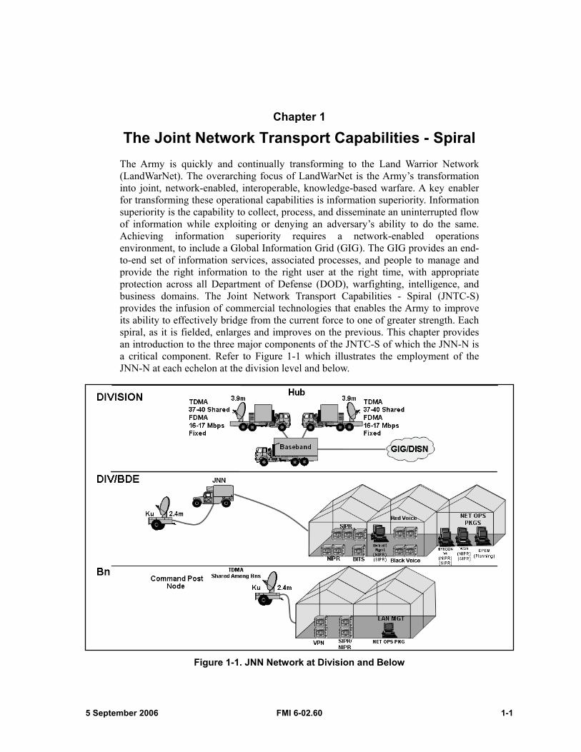
The Joint Network Transport Capabilities - Spiral The Army is quickly and continually transforming to the Land Warrior Network (LandWarNet). The overarching focus of LandWarNet is the Army’s transformation into joint, network-enabled, interoperable, knowledge-based warfare. A key enabler for transforming these operational capabilities is information superiority. Information superiority is the capability to collect, process, and disseminate an uninterrupted flow of information while exploiting or denying an adversary’s ability to do the same. Achieving information superiority requires a network-enabled operations environment, to include a Global Information Grid (GIG). The GIG provides an end-to-end set of information services, associated processes, and people to manage and provide the right information to the right user at the right time, with appropriate protection across all Department of Defense (DOD), warfighting, intelligence, and business domains. The Joint Network Transport Capabilities - Spiral (JNTC-S) provides the infusion of commercial technologies that enables the Army to improve its ability to effectively bridge from the current force to one of greater strength. Each spiral, as it is fielded, enlarges and improves on the previous. This chapter provides an introduction to the three major components of the JNTC-S of which the JNN-N is a critical component. Refer to Figure 1-1 which illustrates the employment of the JNN-N at each echelon at the division level and below.
Figure 1-1. JNN Network at Division and Below

Chapter 1
1-2 FMI 6-02.60 5 September 2006
JOINT NETWORK TRANSPORT CAPABILITIES - SPIRAL 1-1. Commanders have been unable to leverage strategic and tactical information obtained from a single network to gain a tactical advantage over the enemy. The ability to obtain information from the Army’s portion of the GIG and to enable better decisions for precision engagement, maneuver, or information operations is vital for the sustainability and employment of current forces.
1-2. In order to obtain informational superiority, the current tactical communications systems must be capable of high mobility and joint and strategic interoperability. To gain this interoperability, modernized communications teams must use like equipment or compatible government off-the-shelf (GOTS) and commercial off-the-shelf (COTS) equipment found in the GIG infrastructure, while maintaining tactical mobility.
1-3. Joint and strategic interoperability underpins the efforts to create a single integrated communications package that enables the brigade combat team (BCT) to deploy autonomously, to work directly for a joint headquarters (e.g., joint force land component command, joint task force, or other joint force component commands), or work for a division or corps.
1-4. Bridge to future networks is the Army’s near term solution to the current bandwidth capability gap as it transitions to the Warfighter Information Network-Tactical (WIN-T). It provides a solution to the near-term operational requirements for beyond line of sight (BLOS) capability and integrates commercial satellite programs with military programs. The use of the commercial Ku band is critical to this initiative and is used extensively. The supporting system architecture is the JNTC-S.
1-5. The three major transport components of JNTC-S that use commercial-based satellite communications (SATCOM) systems are the combat service support (CSS) SATCOM, Trojan Special Purpose Integrated Remote Intelligence (SPIRIT), and the JNN-N.
CSS SATCOM 1-6. The CSS SATCOM provides wideband Non Secure Internet Protocol Router Network (NIPRNET) connectivity to all major sustainment nodes across the Army. The CSS SATCOM enables deployed maneuver and support battalions to reach key sites located in the continental United States (CONUS) and in sanctuary. It is combined with the wireless CSS Automated Information Systems Interface (CAISI) system to provide flexible connectivity down to the unit level logistics systems (ULLS) ground, and ULLS-S4 system. Refer to Figure 1-2 which illustrates the JNTC-S Support for Sustainment Units.

The Joint Network Transport Capabilities - Spiral
5 September 2006 FMI 6-02.60 1-3
Figure 1-2. JNTC-S Support for Sustainment Units
TROJAN SPIRIT 1-7. Trojan SPIRIT is a military intelligence operated system that is a critical network enabler for the commander and the intelligence elements. It is currently the primary network capability connecting the deployed user to Top Secret Sensitive Compartmented Information (TS/SCI) networks which include the Joint Worldwide Intelligence Communications System (JWICS) and the National Security Agency (NSA) network. Seventeen locations within the division have now been identified as requiring TS/SCI points of presence or connectivity (to include three per BCT). Currently there are two Trojan SPIRITs designated for the division; one Trojan SPIRIT for the BCT and the remaining points of presence will be tunneled through the Joint Network Node (JNN) components via KG-175 tactical fastlane (TACLANE) in-line network encryption (INE) devices. Figure 1-3 depicts the Trojan SPIRIT at division or brigade being tunneled through the JNN to other points of presence that do not have a dedicated Trojan SPIRIT. This is done by using a KG-175 within the respective TS/SCI enclaves.

Chapter 1
1-4 FMI 6-02.60 5 September 2006
Figure 1-3. JNTC-S Military Intelligence Support
5 September 2006 FMI 6-02.60 2-1
Chapter 2
Joint Network Node-Network Army and joint operations are required to pass high volumes of data over greater distances while maintaining a high degree of flexibility and mobility. Many of the information exchanges are critical, time-sensitive, and must be analyzed and used quickly. The JNN-N provides this capability though a suite of voice, video, and data communication tools designed to meet the needs of the division, brigade, and battalion command post structure. This chapter provides an overview of the components that make up the JNN-N and describes the employment at different levels.
NETWORK DESCRIPTION 2-1. The JNN is a suite of communications equipment, housed in transportable shelters and associated transit cases, for the purpose of providing the resources for the network manager to exercise effective control over communication links, trunks, and groups within a deployed network. The JNN-N provides the capabilities to interface those resources with satellite and terrestrial transmission resources to establish a robust network consistent with the Army's vision for the modular division and BCT force structure down to the battalion command post level. The JNN-N is comprised of five fielded major communications nodes, transit cases, and Ku band satellite transportable terminals for the division through battalion levels.
UNIT HUB NODE 2-2. The Unit Hub Node (UHN) connects the time division multiple access (TDMA) and frequency division multiple access (FDMA) Ku band satellite network architectures together. The UHN provides end-to-end Ku band satellite link network connectivity which will allow tactical JNN access into the standard tactical entry point (STEP), teleport, Defense Information Systems Network (DISN), and the Defense Switched Network (DSN) services. The UHN consists of three major communications assemblages: the baseband shelter and two combined TDMA and FDMA satellite shelters. The following paragraphs provide basic descriptions and capabilities of the UHN.
Baseband Shelter
2-3. The baseband UHN is housed in a transportable shelter and transported on a 5-ton family of medium tactical vehicles (FMTV) with one 35 kW diesel generator. The first two iterations (spiral 1) were fielded on commercial semi tractor-trailers with one 40 kW generator. The baseband UHN is a transportable circuit switched and IP-based nodal communications system that supports the modular BCT and division force structure. The baseband shelter is equipped with the necessary components to interface with the JNN, command post node (CPN), and the GIG via Ku band satellite. Equipment included within the baseband shelter are routers, switches, firewalls, servers, communications security (COMSEC) equipment, conditioned diphase modems, media converters, one transmission resource controller (TRC) multiplexer, and one private branch exchange (PBX). The baseband shelter serves as the divisional interface point into the GIG, which pulls services such as SECRET Internet Protocol Router Network (SIPRNET), NIPRNET, and DSN via fiber optic connection. Appendix A contains a detailed listing of components and interconnectivity for the baseband shelter.
Chapter 2
2-2 FMI 6-02.60 5 September 2006
TDMA and FDMA Satellite Vans 2-4. TDMA is digital transmission technology that allows a number of users to access a single radio frequency (RF) carrier without interference by allocating unique time slots to each user within each carrier separated by time. FDMA is a static multiple access technique where transponder bandwidth is subdivided into smaller frequency bands or subchannels. Each subchannel is then assigned to a specific user. This method is frequently used, but it does not readily adapt to changing traffic loads. The UHN fielded in spiral one had two satellite vans – one dedicated to TDMA and one to FDMA. Subsequent fielding’s also had two satellite vans with each van containing both TDMA and FDMA equipment. The TDMA and FDMA satellite vans are housed in a transportable shelter and have two commercial 20 kW diesel generators mounted on a 5-ton FMTV truck bed and two commercial 3-ton environmental control units (ECUs). Within each of the satellite vans is a master reference terminal (MRT) for all the TDMA subnets (one subnet per BCT, brigade, and division). Appendix A contains a detailed listing of components and connectivity between the satellite vans and the baseband shelter.
JNN 2-5. The JNN is located at the division and BCT levels. The JNN consists of a high-mobility multipurpose wheeled vehicle (HMMWV) mounted S-250 shelter communications platform that allows a division and BCT headquarters to assume control of critical pieces of network services, network management, and prioritization when the division and BCT fights as a whole. The division and BCT JNN connect into the UHN for end-to-end network service connection into the GIG, DISN, and DSN. With the use of a division and BCT JNN, the divisional and BCT G-6 or S-6 will assume network responsibility from Network Enterprise Technology Command (NETCOM) to allow the communications support plan to mirror the tactical priority of effort.
2-6. The JNN supports user interfaces into NIPRNET and SIPRNET data networks. There are four transit cases to support the user interfaces into red and black voice networks, network and management service components, and voice over internet protocol (VoIP) phones. One additional transit case containing the Battlefield Video Teleconferencing (BVTC) which provides the management of teleconferencing using both H.320 and H.323 multimedia communication standards. There is one 2.4M dish Ku band satellite transportable terminal (STT) fielded with the JNN to provide direct reachback capabilities to higher command and or strategic enclaves using FDMA and TDMA
2-7. The JNN can provide up to 3 Mbps FDMA satellite communications and is capable of shared bursts up to 4 Mbps to the CPN. The JNN is also capable of simultaneous STEP and or joint interface through the UHN to provide NIPRNET and SIPRNET access. Figure 2-1 shows a typical JNN with its associated equipment at the division and BCT levels. Appendix B contains a detailed list of components and connectivity of the JNN.
CPN 2-8. The CPN interface cases are a group of deployable transit cases located at the division, BCT, and battalion level. At the division and BCT level, the CPN transit cases are deployed with the JNN shelter. The SIPRNET and NIPRNET transit cases provide data services to subscribers in the network, voice switching functions which provide VoIP, transmission system Ku band services (TDMA and FDMA), and user local area network (LAN) services for the subscriber to mesh into the GIG. Refer to Appendix C for further information.

Joint Network Node-Network
5 September 2006 FMI 6-02.60 2-3
Figure 2-1. JNN and Associated Equipment
2-9. Following are the major networking capabilities provided by JNN to support network enabled voice, data, and video services:
Supports 32 secure telephone equipment (STE) subscribers (also supports 2 dial central office [DCO] connections).
Supports 48 2-wire phone subscribers (SIPRNET and NIPRNET). Supports 24 Internet Protocol (IP) voice subscribers (SIPRNET and NIPRNET). Supports 46 IP data subscribers (SIPRNET and NIPRNET) (includes 24 data subscribers
connected to IP phones). Supports one local black Private Branch Exchange (PBX) Transmission Level 1 Signal (1.544
Mbps or tier 1) T1 trunk. Supports 8 MSE black long local voice subscribers. Supports Defense Red Switch Network (DRSN) long local access to the TRC via a Pairgain
modem. Supports remote BVTC access to the TRC via a Pairgain modem. Supports 2 MSE Digital Transmission Group (DTG) supporting voice and data.
2-10. The JNN facilitates the management of digital groups, trunks, and circuits. It provides the means through which the communications resources at a node can be monitored, controlled, and managed. JNN capabilities include Ethernet switching, IP routing, network management, and network security services that include network intrusion detection.
TRANSMISSION CAPABILITIES 2-11. The JNN provides a high-speed and high-capacity backbone communications network focused on rapidly moving information in a manner that supports commanders, staff, functional units, and capabilities-based formations. The JNN-N enables commanders to plan, prepare, and execute multiple missions and tasks simultaneously. The JNN-N connects to the GIG, through the UHN and provides autonomous brigade

Chapter 2
2-4 FMI 6-02.60 5 September 2006
operations by allowing brigade networking access and capabilities without requiring traditional division or higher echelon communication support. The JNN-N will also provide NIPRNET connectivity down to the battalion level of operations. The JNN-N capabilities provide joint and coalition connectivity and allow for interfacing to current network communications systems through:
STEP. BLOS. Line of sight (LOS).
2-12. The STEP and teleport sites provide multiband, multimedia, and worldwide reachback capabilities to DISN in addition to providing a variety of voice, video, and data transport services to classified and unclassified users. The STEP and teleport sites support high throughput and multiband and multimedia telecommunications services for deployed forces of all services in all operational scenarios.
2-13. The Ku band STT is the primary link connectivity to provide DISN services through the UHN to the JNN. To ensure continuity of DISN services, a secondary network or link connectivity may be established to the STEP or teleport site to ensure that there is no break in DISN services in the event the primary (Ku band) link experiences network connectivity outages.
2-14. Regional STEP or teleport sites provide the following services on a requested or as-needed basis. Data Services:
NIPRNET. SIPRNET.
Voice Services: DSN - A worldwide private-line telephone network. DRSN - A global secure voice service which provides the President, Secretary of Defense,
Joint Chiefs of Staff, combatant commanders, and selected agencies with command and control secure voice and voice-conferencing capabilities up to the TS/SCI level.
Video Services: DISN video services provide interoperable dial-up and dedicated subscriber services for
point-to-point and multipoint video conferencing. Provide a means to communicate within the different SATCOM systems.
BLOS INTERFACING CAPABILITIES 2-15. The JNN is designed to interface with existing satellite Ku band and ground mobile forces (GMF) transport systems. The JNN can also interface with the typical SATCOM systems to provide reach and or range extension capabilities such as the Secure Mobile Anti-jam Reliable Tactical Terminal (SMART-T) AN/TSC-154 and the Flyaway Tri-Band Satellite Terminal (FTSAT) AN-USC-60A. These SATCOM terminals can provide alternate and additional reach capabilities to the area of operations (AO) and STEP or teleport sites in addition to range extension capabilities. The following paragraphs provide a brief description of these typical communication transport systems that are most likely to interface with the JNN.
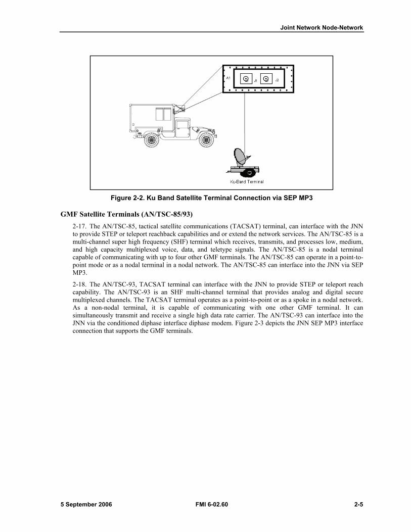
Ku Band Satellite Terminal 2-16. At the division and BCT level, the JNN is fielded with a STT to provide access to the Ku band commercial satellite constellation to support FDMA and TDMA networks. At the battalion level the STT provides TDMA access only. Each level provides reach and or reachback capabilities to a higher command and strategic enclaves. The 2.4M Ku band satellite trailer interfaces into the JNN via the Ku modems and or conditioned diphase interface (CTM-100) modems. Figure 2-2 illustrates the JNN signal entry panel (SEP) MP3 A1 interface connection which supports the Ku band SATCOM terminal. Refer to Appendix D for setup and equipment information.
Joint Network Node-Network
5 September 2006 FMI 6-02.60 2-5
Figure 2-2. Ku Band Satellite Terminal Connection via SEP MP3
GMF Satellite Terminals (AN/TSC-85/93) 2-17. The AN/TSC-85, tactical satellite communications (TACSAT) terminal, can interface with the JNN to provide STEP or teleport reachback capabilities and or extend the network services. The AN/TSC-85 is a multi-channel super high frequency (SHF) terminal which receives, transmits, and processes low, medium, and high capacity multiplexed voice, data, and teletype signals. The AN/TSC-85 is a nodal terminal capable of communicating with up to four other GMF terminals. The AN/TSC-85 can operate in a point-to-point mode or as a nodal terminal in a nodal network. The AN/TSC-85 can interface into the JNN via SEP MP3.
2-18. The AN/TSC-93, TACSAT terminal can interface with the JNN to provide STEP or teleport reach capability. The AN/TSC-93 is an SHF multi-channel terminal that provides analog and digital secure multiplexed channels. The TACSAT terminal operates as a point-to-point or as a spoke in a nodal network. As a non-nodal terminal, it is capable of communicating with one other GMF terminal. It can simultaneously transmit and receive a single high data rate carrier. The AN/TSC-93 can interface into the JNN via the conditioned diphase interface diphase modem. Figure 2-3 depicts the JNN SEP MP3 interface connection that supports the GMF terminals.

Chapter 2
2-6 FMI 6-02.60 5 September 2006
Figure 2-3. GMF Satellite Terminal Connection via SEP MP3
SMART-T (AN/TSC-154) 2-19. The SMART-T is a transportable satellite communications system that provides robust, anti-jam, low probability of intercept (LPI) communications. The SMART-T may be used to extend JNN services BLOS. The SMART-T interfaces into the JNN via the CX-11230 conditioned diphase modem. Figure 2-4 depicts the JNN SEP MP1 interface connections that support the SMART-T assemblage.
Figure 2-4. SMART-T Terminal Connection via SEP MP1

Joint Network Node-Network
5 September 2006 FMI 6-02.60 2-7
FTSAT (AN/USC-60A) 2-20. The AN/USC-60A, FTSAT, is a COTS terminal supporting theater deployed communications and special user requirements. It is a small, lightweight tri-band satellite communications terminal. The FTSAT can operate on C-band, X-band, and Ku band frequencies. The FTSAT can provide STEP and teleport connectivity to provide GIG, DSN, DISN services to the JNN or be used to extend BLOS services. The FTSAT interfaces into the JNN via SEP MP3. Figure 2-4 above depicts the JNN SEP MP1 A1, A2, A3, and A4 interface connections that support the FTSAT assemblages.
LOS INTERFACING CAPABILITIES 2-21. The JNN is designed to interface with existing terrestrial LOS systems (e.g., high capacity line of sight (HCLOS) systems: AN/TRC-190(V)3; LOS, AN/TRC-190 (V1); and the Tropospheric Scatter Radio terminal [TROPO], AN/TRC-170) to extend network services to modular forces.
2-22. The HCLOS radio (V3) is a terrestrial, microwave radio system capable of 8 Mbps of data throughput which can vary depending on the radio band selected. Each AN/TRC-190(V3) is equipped with three HCLOS radios and provides up to 25 miles of extended range communication capabilities. The AN/TRC-190(V3) interfaces into the JNN via the Quad Multiplexer (QMUX) (JNN spiral 1) or the Flex Multiplexer (FLEXMUX) (JNN spirals 2-7), Fiber Optic Modem (FOM), or Tactical Fiber Optic Cable Assembly (TFOCA). Figure 2-5 depicts the JNN SEP MP2 interface connections which support the HCLOS assemblages.
Figure 2-5. HCLOS (V1) and (V3) Terminal Connection via SEP MP 2
TROPO Terminal (AN/TRC-170) 2-23. The TROPO terminal interfaces with the JNN to provide BLOS and LOS capability. The AN/TRC-170 is a transportable, self-enclosed tropo-scatter terminal (multi-channel) capable of transmitting and receiving analog and digital data over varying distances (up to 100 miles). The TROPO terminals are deployed at hybrid nodes for internodal and extended range (skip node) communications. The AN/TRC-170 radio terminal will extend the JNN network services up to 100 miles and interfaces into the JNN via the diphase modem. Refer to Figure 2-6 for the overview of the over-the-air communications links.

Chapter 2
2-8 FMI 6-02.60 5 September 2006
Figure 2-6. Over-the-Air Communications Links
CONNECTIVITY TO CURRENT NETWORKS 2-24. The JNN at the division and or BCT levels provides a high-speed wide area network (WAN) infrastructure that connects the BCT main command post (CP) to the joint voice and data networks. The JNN allows tactical users to interface into the GIG, joint, interagency organizations, and the division headquarters. The JNN is also interoperable with commercial networks and current force communications networks (e.g., mobile subscriber equipment [MSE] and Tri-Service Tactical Communications Program [TRI-TAC]). The JNN interfaces with high bandwidth satellite and terrestrial data transmission systems currently in the Army inventory providing video teleconferencing, email, and local area network services. The JNN can support two MSE and TRI-TAC DTGs via the diphase modems, DTG modem, or the Vantage. The JNN connects directly to the following systems:
MSE - The JNN can support two MSE digital transmission groups. Typically, the following assemblages will interface into the JNN:
NODE CENTER SWITCH (NCS) - The JNN can provide DISN services to the NCS which in turn provides essential switching, traffic control, and access points for MSE. The NCS interfaces into the JNN via the CX-11230 cable on SEP MP1.
FORCED ENTRY SWITCH (FES) - The JNN can provide DISN services to the FES. LEN - The JNN can provide DISN services to the LEN switch.
TRI-TAC – The TRI-TAC communication networks consist of components that ensure subscribers have the capability to transmit and receive voice, data, and video. The JNN can support two TRI-TAC DTGs. Typically the following assemblages will interface into the JNN:
AN/TTC-39D SWITCH - The JNN can provide DISN services to the AN/TTC-39D switch.

Joint Network Node-Network
5 September 2006 FMI 6-02.60 2-9
AN/TTC-56 – The JNN can provide DISN services to the AN/TTC-56 Single Shelter Switch (SSS).
2-25. The Vantage provides an H.323 gateway between tactical and commercial networks. The Vantage takes various types of network elements (Integrated Services Digital Network [ISDN], IP, radio, and analog voice) and allows distant ends to talk to each other while providing services such as affiliation and or disaffiliation, routing, bandwidth, and link management. JNN VoIP subscribers register with the Vantage and receive a Tactical User ID (TUID)) for communication within the tactical Time Division Multiplexer (TDM) network.
JNN CPN TRANSIT CASES 2-26. The JNN CPN cases are a group of lightweight deployable transit cases that consist of SIPRNET and NIPRNET communication processing equipment for voice and data functions at the division and BCT level. At the division and BCT level the CPN transit cases are deployed with the JNN shelter. The SIPRNET and NIPRNET transit cases provide data services to subscribers in the network, voice switching functions which provide VoIP, transmission system Ku band services (TDMA and FDMA), and user LAN services for the subscriber to mesh into the GIG. The SIPRNET data cases consist of data case A, data case B, and an Uninterruptible Power Supply (UPS) case. The NIPRNET data cases consist of the data case B and an UPS case.

This page intentionally left blank.

3-1 FMI 6-02.60 5 September 2006
Chapter 3
Employment of the Joint Network Node-Network at the Division, Brigade, and Battalion Level
The JNN-N is designed to be employed at all levels of the Army structure and fully supports the modularity concept of the Army. The JNN-N is scalable to provide capabilities necessary to support different CPs ranging from battalion CPs to larger and more complex CPs at the brigade and division. This chapter discusses the employment of the JNN-N at the division, brigade, and battalion.
DIVISION 3-1. The division headquarters uses all components of the JNN-N. This section describes the employment of the JNN-N at division.
UNIT HUB NODE 3-2. The UHN is used to provide the division access into the STEP or teleport range of services. The hub is located in close proximity to the STEP and is usually cabled into its network. One UHN is fielded at the division level for this requirement. In order to increase the responsiveness of a complex network and to facilitate the bandwidth required to support the division headquarters and BCT networks, the division can employ a network operations (NETOPS) cell with the UHN. The G-6 will exercise control of the network and NETOPS through the UHN. The MRT at the UHN allows the TDMA mesh resources to be allocated across the division and provide the means to ensure that priority units, down to the battalion level, have the necessary bandwidth to accomplish their mission. The UHN flattens the disparate TDMA satellite network structure and increases the bandwidth capability from approximately 6 Mbps to 40 Mbps, while an embedded NETOPS cell can provide the management to enable the division network.
3-3. The network hub platoon of the division network support company contains the personnel to install and operate the baseband shelter and satellite shelters. Table 3-1 shows the structure of the network hub platoon. MOS 25N (Nodal Network Systems Operator-Maintainer) has been approved and will be reflected in place of MOS 25F (Switch Systems Operator-Maintainer) in the operation of the JNN-N at the division and brigade levels.
Table 3-1. Network Hub Platoon
Rank MOS Position O2 25A00 Platoon Leader W3 250N Network Management Technician E7 25S40 Platoon Sergeant Baseband Team E6 25F30 Switch System Supervisor E5 25B20 Senior LAN Manager E5 25F20 Senior Switch Sys Operator-Maintainer E4 25B10 LAN Manager TDMA Multiband Team E5 25S20 TACSAT System Team Chief

Chapter 3
3-2 FMI 6-02.60 5 September 2006
Table 3-1. Network Hub Platoon
Rank MOS Position E4 25S10 TACSAT System Operator-Maintainer E3 25S10 TACSAT System Operator-Maintainer FDMA Multiband Team E5 25S20 TACSAT System Team Chief E4 25S10 TACSAT System Operator-Maintainer E3 25S10 TACSAT System Operator-Maintainer Hub Support Team E5 25B20 Senior LAN Manager E4 25B10 LAN Manager E3 25U10 Signal Support System Specialist E4 25L10 Cable System Installer Maintainer E4 25L10 Cable System Installer Maintainer
JOINT NETWORK NODE 3-4. There are typically three JNNs located within the division headquarters to support three command and control elements: division main command post (CP) and the tactical command posts (TAC CPs) 1 and 2. The TAC CP provides the commander the flexibility to organize continuous full spectrum operations. The division main CP may be located anywhere within the division AO but is larger and thus entails a longer time to set up and tear down. For this reason the main CP typically will set up in a semi-stationary base within the theater or sanctuary. The JNN provides the division G-6 the means to exercise network control from the main CP and the two TAC CPs. The G-6 also provides NETOPS support for the CPs through the division network, operations, and security center.
3-5. The division headquarters may deploy with command and control of six BCTs and possibly other service land forces. If the division is given command and control of other service land components, additional joint manning and network management equipment may be necessary to support the mission. An example of network management equipment is the Joint Network Management System which is not doctrinally allocated to division level forces.
3-6. In addition to expanding bandwidth, the division has the capability to dynamically reassign the bandwidth so that the communications support plan matches the division commander’s ground tactical plan. The division UHN, through the MRT, ordinarily provides this. If a BCT is deployed autonomously it can be equipped with a push package containing an MRT to control the bandwidth of its subordinate battalions through the JNN. This provides an unprecedented capability to adjust bandwidth on demand to those who need it to enable the ground tactical plan.
3-7. The division and BCT will be equipped with the necessary JNN assemblages and equipment which may vary depending on the division mission, to provide network services to modular formations (e.g., division, BCT, and battalion [BN]) to meet their current information requirements. Figure 3-1 illustrates the various connectivity services between the division, BCT, BN CPN, and STEP or teleport locations.
HCLOS 3-8. Each JNN section has an AN/TRC-190(V) 3 (HCLOS) capable of providing up to 8mbps of data throughput. At division there are three HCLOS, and two at each BCT, allocated to be used with the JNN-N. The HCLOS can be used to establish connectivity with the three division CPs or subordinate BCTs. The HCLOS is used to provide additional bandwidth when the satellite bandwidth becomes saturated, when the mission dictates, when the terrain allows, and for sustainment operations. The HCLOS can also be used for establishing communications with MSE equipped units.

Employment of the Joint Network Node-Network at the Division, Brigade, and Battalion Level
5 September 2006 FMI 6-02.60 3-3
Figure 3-1. Division to BCT Connectivity
BRIGADE COMBAT TEAMS 3-9. The heavy brigade combat team (HBCT), infantry brigade combat team (IBCT), and Stryker brigade combat team (SBCT) have two JNNs to support a main CP and a TAC. The brigade S-6 typically operates out of the brigade Nodal Operations Security Center (BNOSC) located at the main CP and based on mission requirements, plans, coordinates, and directs the execution of the brigade communications support plan using the JNN as his focal point. The JNN will typically be emplaced near the CP with the voice and data cases for NIPRNET and SIPRNET located within the brigade NOSC. The S-6 will exercise monitoring and control of the brigade network using the management tools. Figure 3-2 shows a representative CP at the BCT level. The employment of the JNN is essentially the same at the division and BCT level with the exception of the authorized manning levels, control functions, and planning characteristics.

Chapter 3
3-4 FMI 6-02.60 5 September 2006
Figure 3-2. Representative CP Configuration
3-10. The JNN team establishes communications and extends the capabilities from the van via TFOCA II to the SIPRNET and NIPRNET voice and data transit cases in the CP. The individual sections under the guidance of the S-6 will connect their systems.
3-11. In addition to the Ku satellite trailer, each JNN has an AN/TRC-190(V3) HCLOS to establish connectivity to adjacent brigades or subordinate battalions as needed. This provides a traffic capability of 8 Mbps to adjacent brigades and 2 Mbps to subordinate battalions when the battalion is equipped with an AN/TRC-190(V1) LOS.
3-12. There are two network extension platoons in the BCT network support company which contain the personnel to operate the JNN. Table 3-2 lists the personnel required in the JNN section. MOS 25N has been approved and will be reflected in place of 25F in the operation of the JNN-N at the division and brigade levels. Refer to page 3-1. MOS 25Q (Transmission Systems Operator-Maintainer) has been approved to replace 25F as the Range Extension Operator and will be reflected on future manning documents.
Table 3-2. Joint Network Node Section
Rank MOS Position E6 25F30 Extension Switch Supervisor E5 25F20 Sr Switch System Operator-Maintainer E3 25F10 Extension Switch Operator-Maintainer E4 25F10 Range Extension Operator E5 25S20 TACSAT System Team Chief E4 25S10 TACSAT System Operator-Maintainer E3 25S10 TACSAT System Operator-Maintainer

Employment of the Joint Network Node-Network at the Division, Brigade, and Battalion Level
5 September 2006 FMI 6-02.60 3-5
COMMAND POST NODE 3-13. There is one CPN located at the brigade level to provide support to the mobile command group or TAC CP based on mission requirements. Table 3-3 shows the composition of the CPN support section.
Table 3-3. Command Post Support Section
Rank MOS Position E5 25Q20 Senior Transmission Systems Operator-Maintainer E3 25Q10 Transmission Systems Operator-Maintainer E4 25B10 Information Systems Specialist E3 25B10 Information Systems Specialist
BATTALION 3-14. There is one CPN located at the battalion level to provide voice and data capabilities. It uses TDMA satellite transmission to gain access through the JNN or UHN to the GIG. The CPN consists of a Ku band trailer and associated transit cases to provide a wide array of services. Figure 3-3 shows battalion connectivity to the brigade using the TDMA mesh.
3-15. The CPN is located at the battalion CP, and the battalion S-6 typically exercises control from this location. The equipment that is used to interface with the CPN in the CP is organic to the unit; therefore the unit sets up and operates the equipment with technical oversight from the S-6. The battalion may have an AN-TRC-190(V1) assigned, to provide a 2 Mbps traffic capability to the brigade when the mission dictates. The personnel to operate the CPN are assigned to the S-6 section.
Figure 3-3. Battalion Command Post Connectivity

This page intentionally left blank.
5 September 2006 FMI 6-02.60 4-1
Chapter 4
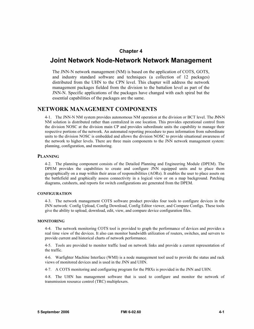
Joint Network Node-Network Network Management The JNN-N network management (NM) is based on the application of COTS, GOTS, and industry standard software and techniques (a collection of 12 packages) distributed from the UHN to the CPN level. This chapter will address the network management packages fielded from the division to the battalion level as part of the JNN-N. Specific applications of the packages have changed with each spiral but the essential capabilities of the packages are the same.
NETWORK MANAGEMENT COMPONENTS 4-1. The JNN-N NM system provides autonomous NM operation at the division or BCT level. The JNN-N NM solution is distributed rather than centralized in one location. This provides operational control from the division NOSC at the division main CP and provides subordinate units the capability to manage their respective portions of the network. An automated reporting procedure to pass information from subordinate units to the division NOSC is embedded and allows the division NOSC to provide situational awareness of the network to higher levels. There are three main components to the JNN network management system: planning, configuration, and monitoring.
PLANNING 4-2. The planning component consists of the Detailed Planning and Engineering Module (DPEM). The DPEM provides the capabilities to create and configure JNN equipped units and to place them geographically on a map within their areas of responsibilities (AORs). It enables the user to place assets on the battlefield and graphically assess connectivity in a logical view or on a map background. Patching diagrams, cutsheets, and reports for switch configurations are generated from the DPEM.
CONFIGURATION 4-3. The network management COTS software product provides four tools to configure devices in the JNN network: Config Upload, Config Download, Config Editor viewer, and Compare Configs. These tools give the ability to upload, download, edit, view, and compare device configuration files.
MONITORING 4-4. The network monitoring COTS tool is provided to graph the performance of devices and provides a real time view of the devices. It also can monitor bandwidth utilization of routers, switches, and servers to provide current and historical charts of network performance.
4-5. Tools are provided to monitor traffic load on network links and provide a current representation of the traffic.
4-6. Warfighter Machine Interface (WMI) is a node management tool used to provide the status and rack views of monitored devices and is used in the JNN and UHN.
4-7. A COTS monitoring and configuring program for the PBXs is provided in the JNN and UHN.
4-8. The UHN has management software that is used to configure and monitor the network of transmission resource control (TRC) multiplexers.
Chapter 4
4-2 FMI 6-02.60 5 September 2006
NETWORK MANAGEMENT AT THE DIVISION 4-9. The senior mission commander commands and controls the network. The commander delegates the authority to control and configure the network to the G-6. The G-6 participates in the military decision making process (MDMP) and identifies the optimum placement of network equipment and personnel to achieve the goals of the commander.
4-10. Network operations (NETOPS) control is the authority granted to the senior signal officer by the operational commander.
UNIT HUB NODE 4-11. The management package for the UHN serves as the central point in the network for the devices that require a centralized management server such as firewalls and intrusion detection systems (IDS). There are separate hardware platforms for the SIPRNET and NIPRNET domains. The management tools include:
WMI management. TRC planning software. Network monitoring management software to monitor and configure the PBX. Network management software to configure and monitor routers. Firewall and IDS managers. TACLANE management software to monitor and control KG-175’s in the network. MRT that supports the management and planning of the SATCOM network.
DIVISION MAIN (DMAIN) G-6 4-12. The network management tools provided to the DMAIN G-6 are designed to aid in the planning and management of the TOC LAN. These tools are —
DPEM. Integrated system control (ISYSCON V4). Software to monitor and manage the LAN. Separate laptops to control the SIPRNET and NIPRNET domains.
DMAIN NETOPS 4-13. The NETOPS section will work in conjunction with the DMAIN G-6 and will always be collocated with a JNN. It contains the necessary tools for planning and to manage the WAN, administer and monitor IDS and firewalls, software to manage TACLANEs in the network, and separate platforms for the SIPRNET and NIPRNET domains.
DMAIN JNN 4-14. The JNN package includes a limited planning capability for the TACLANEs. WMI is used to monitor the JNN components within the network and has the capability to monitor link status.
DIVISION TAC CP 1 AND CP 2 G-6 4-15. The DTAC G-6 section has the same capabilities as the DMAIN G-6 section with the exception that it does not contain the capability of the DPEM. The DTAC G-6 section does have the capability to monitor and manage the DTAC LAN.
DIVISION TAC CP 1 AND CP 2 NETOPS 4-16. The division TAC CP 1 and CP 2 NETOPS section has the same capability as the DMAIN NETOPS section. This section does not have the capability to create detailed plans of the network or control TACLANE management functions.
Joint Network Node-Network Network Management
5 September 2006 FMI 6-02.60 4-3
DIVISION TAC CP 1 AND CP 2 JNN 4-17. The division TAC CP 1 and CP 2 JNNs have the same management capability as the DMAIN JNN.
NETWORK MANAGEMENT AT THE BRIGADE 4-18. Network management at the brigade level is performed from the BNOSC controlled by the brigade S-6, which includes personnel assigned to the S-6 section and NSC which is primarily performed from the BNOSC. The capabilities include monitoring and controlling the networks within its AOR based on the mission and orders from division. It also includes the control and monitoring of the assets at battalion. The following management packages are used at brigade:
The BNOSC S-6 management package consists of the tools to manage and control the CP LAN and to provide the capabilities necessary in the event the brigade deploys autonomously.
The brigade NETOPS section is provided essentially the same management package as the division NETOPS section. The WAN management capability controls and monitors down to the battalion level, and automatically forwards information to the division NETOPS section.
The brigade main JNN management package is the same as provided at the division JNN. The brigade TAC CP S-6 section is provided the same management tools as the BNOSC without
the ability for network planning. The brigade TAC JNN has the same management package as the division main JNN.
AUTONOMOUS BRIGADE DEPLOYMENT 4-19. In the event that the brigade is deployed autonomously, additional management and control tools are required, which are provided in a push package for the NETOPS section to perform the functions ordinarily performed by the division. These tools include:
MRT to manage and control SATCOM assets. TACLANE management application. IDS Remote Management.
NETWORK MANAGEMENT AT THE BATTALION 4-20. The battalion S-6 management functions will be limited to monitoring and controlling the LAN with the ISYSCON V4. One platform is used with removable hard disk drives (RHDDs) for the SIPRNET and NIPRNET domains.

This page intentionally left blank.

5 September 2006 FMI 6-02.60 A-1
Appendix A
Unit Hub Node Component Listing The UHN is a deployable communications support package that integrates, manages, and controls the interfaces between the communications assets within the division network. Figure A-1 depicts a division network satellite systems overview. When fully populated, the UHN can support a division network of 16 FDMA links and 16 TDMA nets. Figure A-2 shows the interconnections between the baseband shelter and the satellite vans. This appendix discusses the components that comprise the UHN baseband van and an overview of the UHN satellite vans.
Figure A-1. Division Network Satellite Systems Overview

Appendix A
A-2 FMI 6-02.60 5 September 2006
Figure A-2. Baseband and Satellite Vans Interconnections
BASEBAND SHELTER A-1. The UHN baseband shelter is comprised of components located in an S-280 shelter and includes routers, firewalls, servers, transmission resource center, media converters, flexmux, and COMSEC devices divided into separate NIPRNET and SIPRNET domains. The shelter has seven functional areas:
NIPRNET data. SIPRNET data. Voice switching. Transmission systems. Patching. Network management. Power.
A-2. The NIPRNET and SIPRNET data sections provide basic data and server services to subscribers in each domain. The data networks are designed to provide information assurance functions to data subscribers. The voice switching function provides the equipment necessary to service voice and data subscribers, both locally and to subordinate units. The voice function also provides support for current forces subscribers and interface to commercial switching assets external to the UHN baseband. The patching and network management capabilities provide the necessary functions to route, reroute, monitor, and troubleshoot circuits in the network. Equipment is also provided for timing distribution and line conditioning. The transmission functional system includes multiplexer and modem functions to provide equipment to multiplex lower data rate signals into larger aggregate signals and convert, as necessary, to a format suitable for transport through the tactical network. It also includes the COMSEC function to supply equipment used to protect and encrypt data and transmission lines from hostile interception. The power subsystem provides the capabilities to connect to power sources and distribute power to the UHN baseband shelter. The network management function provides capabilities to plan and manage the implementing circuits, trunks, and transmission systems for the WAN.

Unit Hub Node Component Listing
5 September 2006 FMI 6-02.60 A-3
UHN COMPONENTS A-3. The voice and data equipment are in separate racks that contain the same components in order to support the NIPRNET and SIPRNET domains. The following descriptions apply to both the SIPRNET and NIPRNET domains unless specified. For further information on the components refer to the COTS manual supplied with the equipment.
Global Positioning System (GPS) A-4. A GPS timing source in the baseband shelter provides Stratum 1 timing and synchronization of the various serial devices used in the FDMA network. The GPS recovers clock from the GPS satellite constellation and disciplines an on-board rubidium oscillator, allowing the device to operate in the event of GPS signal loss. The GPS uses the recovered timing to distribute timing to the equipment. An external antenna that is mounted on the front of the shelter provides the GPS input.
Domain Workstations A-5. There are separate workstations and tabletop areas for the NIPRNET and SIPRNET domain. This setup allows the monitoring and configuration of the components in each domain to be user friendly. Each workstation consists of a monitor, keyboard, and trackball.
NIPRNET Tier 1 Routers A-6. The NIPRNET tier 1/1 and tier 1/2 routers perform the following functions:
Public side router used to create a three part security domain. Contains access lists to create a first line of defense for security. Provides links for external connections to an isolation network. Provides serial WAN connections. Will run routing protocols to reach networks within the WAN.
NIPRNETTier 2 Router A-7. The NIPRNET tier 2 router provides default gateway and routing functions for locally connected NIPRNET hosts and shelter components. The tier 2 router contains an Ethernet switch module. The Ethernet switch is used for shelter component Ethernet connections. The NIPRNET tier 2 router has a T1 card that interfaces to the T1 patch panel. The NIPRNET tier 2 router can serve as a gateway between VoIP subscribers and the shelter PBX.
MEDIA CONVERTERS A-8. The 100Base TX to 100Base FX media converters are used in the NIPRNET and SIPRNET data network to convert LAN interfaces from the internal shelter data network to fiber interfaces. There are four media converters used in each network for this purpose. The fiber output of each of the media converters appears on the shelter SEPs as a TFOCA II connector. The fiber optic conversion allows devices to be connected over greater distances than standard shielded twisted pair cable will allow.
KEYBOARD, VIDEO, MONITOR (KVM) SWITCH A-9. Within the two security domains there are multiple devices that require a keyboard, monitor, and pointing device (trackball or mouse). Shelter space availability does not allow for multiple monitors and keyboards within the shelter for each security domain. To allow each machine to have access to the required devices and to minimize the number of devices, a KVM switch has been included in the NIPRNET and SIPRNET domain equipment. A KVM switch allows one keyboard, monitor, and trackball to be switched between different servers, without causing upset on the servers, as the devices are switched in and out. The KVM switch will allow remote IP connection to access any of the processors that are connected to it.

Appendix A
A-4 FMI 6-02.60 5 September 2006
CONDITIONED DIPHASE MODEMS (CDIM) A-10. There are two CTM-100 modems in the NIPRNET domain and one in the SIPRNET that are used to transmit signals over existing copper wire. The modems convert NRZ data to CDI data over fiber, and can also extend fiber from the shelter using CX-11230 or fiber optic cable.
FIREWALL A-11. The COTS firewalls used in the NIPRNET and SIPRNET domains are used to protect the LAN and public servers such as mail, Web, or FTP.
IA CONFIGURATION PANEL A-12. The IA configuration panel is used to patch the IA components together to meet mission requirements.
TACLANE A-13. The UHN baseband has four TACLANEs (E100 and classic). The TACLANE is an INE that provides security for the data passing over the Ku network. The E100 version connects directly to both the NIPRNET and SIPRNET switches via RJ45 connections. The classic version connects to the NIPRNET switch and the GEM server using RJ45 connections.
ETHERNET SWITCH A-14. The UHN baseband has two Ethernet switches used in both the NIPRNET and SIPRNET domains. The Ethernet switches are connected to all the KVM-managed servers as well as the other devices like the TACLANEs and call managers (CM).
HSFEC UNITS A-15. The HSFEC unit provides forward error correction to enhance data transmission over noisy lines. The UHN has three HSFEC units in the shelter. Each unit has two HSFEC functions to yield a total of six HSFEC channels. Each HSFEC channel appears on patch panel 4. The HSFEC can be patched in and configured for standard serial or NIPRNET router serial data to one of the many transport and encryption devices available at the patch panel 4.
NIPRNET SEP A-16. The NIPRNET SEP data interfaces are Ethernet interfaces and appear at the SEP as either wired (cabled) or fiber optic (FO) interfaces. There are four wire or cable interfaces (two for future use), six GMF and EHF cable interfaces, and eight fiber optic interfaces (four for future use). Of the two cable interfaces, one cable connects to the remote NIPRNET tier 1 router; the other connects to the remote NIPRNET tier 2 router. Each wired Ethernet interface has an MS round connector on the SEP. Two 50-foot external cables are provided with the system which converts the MS round connector interface to a standard RJ45 Ethernet cable interface.
SIPRNET DOMAIN A-17. The SIPRNET data network components are similar to the NIPRNET data components. The SIPRNET IA architecture consists primarily of a tier 1 and tier 2 router, separated by a firewall, with an intrusion detection sensor.
A-18. The SIPRNET tier 2 router serial ports connect to patch panel 6, the HSFEC, or directly to KIV-7s. At patch panel 6, the serial ports can be patched to KIV-19s, KIV-7s, or HSFEC units. The SIPRNET connections cannot be patched to black devices without first being interfaced to a crypto device. The Vantage also appears on the SIPRNET domain. The Vantage has an Ethernet connection to the SIPRNET

Unit Hub Node Component Listing
5 September 2006 FMI 6-02.60 A-5
tier 2 router Ethernet switch function. Accompanying the Vantage is a switch for SIPRNET voice gateway functions.
SIPRNET SEP A-19. The shelter SIPRNET SEP contains data interfaces that are Ethernet interfaces off of the SIPRNET tier 1 and tier 2 routers. The Ethernet interfaces appear at the SEP as either wired (cabled) or FO interfaces. There are two wire or cable interfaces and six fiber optic interfaces. One cable interface connects to each of the SIPRNET routers. Each wire Ethernet interface has an MS round connector on the SEP. Two 50-foot external cables are provided with the system which converts the MS round connector interface to a standard RJ45 Ethernet cable interface. The six fiber interfaces are interior router Ethernet interfaces converted to 100Mbps fiber by four separate media converters. These internet interfaces terminate on the SIPRNET tier 2 router. It should be noted that the TFOCA II connector and cables have the capacity for two connections (2 pairs of fiber). The UHN only connects to one of the pairs in the cable.
VOICE SWITCHING A-20. There are separate NIPRNET and SIPRNET domains that mirror each other. The UHN voice components are architected to interface with traditional tactical networks and to combine tactical voice with data networks. The main voice components of the converged UHN voice system are the PBX, Vantage, and CMs. The PBX is a COTS voice switch mounted in the shelter. The Vantage acts as an interface between the current forces tactical network and the VoIP network and can be used to supply flood search routing, tactical numbering, and multi-level precedence and preemption for subscribers. The CM software assists in call supervision and gateway call service for VoIP subscribers. Also included as part of the voice network are the Ethernet switches (one per security domain). The Ethernet switches are used to terminate and provide power to VoIP subscribers. All of the voice components are mounted internal to the shelter.
CM A-21. There are two CMs in the NIPRNET and two in the SIPRNET domain that are main components in the shelter voice architecture. The CM is a software-based call processing station that extends the benefits of IP telephony into current forces telephone systems. This allows administrators to control call processing, assign device limitations, administer dial plans and phone features, and centralize directory services. The CM’s primary functions are as follows:
Call processing. Signaling and device control. Dial plan administration. Phone feature administration.
PBX A-22. The UHN is supplied with a PBX for support of black voice users over the FDMA network. The hub PBX is also used for connectivity to a STEP or teleport site and acts as a gateway to DSN. The PBX has six T1 interfaces that connect to the TRC to provide voice over the FDMA network.
Vantage A-23. The Vantage appears on the SIPRNET domain and acts as an H323 gatekeeper providing services such as affiliation, disaffiliation, routing, bandwidth, and link management to nontactical between the tactical and commercial networks.. VoIP subscribers register with Vantage and receive a TUID for communication with the tactical TDM networks such as MSE and TRI-TAC.
TRC A-24. The UHN TRC is a four-shelf TRC that provides multiplexing of voice (black PBX), data (both SIPRNET and NIPRNET), and video interfaces for transport over the FDMA network. The TRC is the hub’s primary means of transporting these interfaces to the JNNs or to the STEP and teleport sites. The

Appendix A
A-6 FMI 6-02.60 5 September 2006
hub’s TRC provides 12 aggregate trunk interfaces (2 are spares), and space is allocated in the TRC for a total of 16 trunks. The symmetrical-asymmetrical trunk modules (SA-TRKs) may be used for FDMA, cable, GMF SATCOM, or line of sight links. Typically, the TRC links are distributed to the JNNs via the hub’s FDMA satellite van. The TRC port interfaces provide the necessary electrical and functional interfaces for connectivity to the hub’s routers, dedicated encryption devices (DEDs), external video devices, and the shelter’s PBX.
FOM A-25. The FOMs are used to efficiently transport the TRC’s Trunk Encryption Device (TED)-encrypted SA-TRKs between the baseband van and the satellite van for transport over the FDMA network. The FOMs are the primary means of transport to the satellite van for the FDMA TRC links. The fiber outputs are brought to separate 12-pair TFOCA II cables, and are patchable at fiber optic patch panels in both the satellite and the baseband vans.
SATELLITE VANS A-26. When initially fielded, the UHN had two satellite vans; one for FDMA and one for TDMA. Beginning with spiral two, the FDMA and TDMA satellite vans were combined so that each van is equipped to support eight FDMA and eight TDMA links for a total of 16 links each. Both satellite vans contain MRTs that provide timing and management for the TDMA mesh.
A-27. The UHN satellite van is a transportable circuit switched and IP-based communications system that allows for voice and data operation in FDMA and TDMA carrier mode. The UHN is an S-280 shelter mounted on a five-ton FMTV and includes a 3.9M antenna to operate within the Ku band. It is powered by two 20 kW generators mounted on the truck-bed and has two 18k BTU commercial ECUs.

5 September 2006 FMI 6-02.60 B-1
Appendix B
Joint Network Node Components and Connectivity This appendix covers the component listing, installation, operation, and maintenance of the JNN at the division and BCT level. The JNN provides the resources for the network manager to exercise effective control over the communication links, trunks, and groups within a deployed network. The JNN also provides the capabilities to interface those resources with satellite and terrestrial transmission resources to establish a robust network consistent with the Army's vision for the modular force structure. Figure B-1 shows the JNN application from the division to battalion CP level. The battalion CPN is covered in Appendix C. The configuration and settings on the individual equipment contained within the JNN are for illustrative purposes only. The actual configuration and settings will vary based on the unit’s mission and policies in effect and will be in accordance with the Defense Information Systems Agency (DISA) Security Technical Implementation Guide (STIG).
Figure B-1. JNN and BCT Deployment

Appendix B
B-2 FMI 6-02.60 5 September 2006
COMPONENTS B-1. The JNN consists of components located in an S-250 shelter and includes routers, firewalls, servers, transmission resource center, media converters, flexmux, Vantage, TACLANES, and COMSEC devices divided into NIPRNET and SIPRNET domains. Figure B-2 shows the inside roadside view, and Figure B-3 shows the inside curbside view. The following paragraphs provide a description of the shelter components and their operating procedures.
Figure B-2. JNN Roadside View
GLOBAL POSITIONING SYSTEM (GPS) B-2. The GPS, which includes the unit and antenna, is implemented in the JNN as a timing source. The antenna is mounted externally on the shelter and is connected via an external SEP connection. The GPS provides a Stratum 1 timing source with P(Y) coding for anti-spoofing. In the event of satellite unavailability, the device has a disciplined Rubidium backup. The GPS is configurable via a console (serial) port interface to the NIPRNET server. The GPS has eight connections to the GPP for TED Black Station Clock Timing, one connection to the GPP for T1 timing (to the TRC) and one reference clock appearance at the GPP. The components within the JNN are configured to draw all timing from the GPS with a minimum amount of patching.
KVM SWITCH B-3. The JNN has two separate domains (SIPRNET and NIPRNET) which have multiple devices that require a keyboard, monitor, and pointing device (trackball or mouse). Shelter space availability does not allow for multiple monitors and keyboards within the shelter. To allow each machine to have access to the required devices, and to minimize the number of devices, a KVM switch has been included in the domain equipment. The KVM switch allows one keyboard, monitor, and trackball to be switched between different machines, without causing upset on the machine, as the devices are switched in and out. The KVM switch will allow remote IP connection to access any of the processors that are connected to it. There is a separate KVM switch for each of the domains.

Joint Network Node Components and Connectivity
5 September 2006 FMI 6-02.60 B-3
Figure B-3. JNN Curbside View
TERMINAL SERVER B-4. For device configuration and management purposes, the NIPRNET server is required to have a serial or console port interface to the following devices: tier 1 router, tier 2 router, firewall, TRC, CSUMs, GPS, CDIM #1, CDIM #2, CDIM #3, NIPRNET KVM, VPN router, and the PBX. Because there is only one serial port on the server itself, a terminal server device is employed to increase the number of interfaces that the server can simultaneously access. The devices requiring serial or console port management connect to serial ports on the terminal server. The terminal server in turn connects to the server directly via a console port, and indirectly via an Ethernet connection to the tier 2 Ethernet switch module. The terminal server allows access to the connected device’s serial ports via the Ethernet interface. There is a separate server for the NIPRNET and SIPRNET domains.
PATCH PANELS B-5. There are two types of patch panels in the JNN: communications patch panel (CPP) and GPP that are used to manually reconfigure, monitor, and test circuits. The components within the JNN are configured to be normal through and require little or no patching for typical circuits. However, some interfaces are dead-ended at the patch panel to allow for flexibility in configurations. The patch panels will be used primarily to test and monitor circuits.
CPP B-6. The JNN is equipped with two CPPs (one within the NIPRNET domain and one within the SIPRNET domain) which are used to patch multi-pin interfaces from the JNN equipment. The CPP permits normal through connection of digital EQUIP to LINE interfaces, loopback testing of individual channels, and cross patching for channel reassignment. Each CPP is composed of modules housed in an 18-slot chassis.

Appendix B
B-4 FMI 6-02.60 5 September 2006
GPP B-7. The JNN is equipped with three GPPs used to patch NRZ interfaces from the JNN equipment and to patch modulated interfaces. NRZ interfaces are brought to the panel to allow access to individual signals. This configuration allows the JNN operators to access and reconfigure portions of circuits for special configurations or testing. Also the group patch panel is used to patch coaxial signals.
NON-SECURE DATA NETWORK B-8. The NIPRNET data network components are laid out in an IA-based architecture. The IA architecture consists primarily of a tier 1 and tier 2 router, separated by a firewall, with an Intrusion Detection System (IDS). Figure B-4 shows a representative IA-based architecture. The overall NIPRNET data network is shown in Figure B-5. The following sections describe each individual component within the NIPRNET data network.
Figure B-4. Information Assurance-based Architecture
Joint Network Node Components and Connectivity
5 September 2006 FMI 6-02.60 B-5
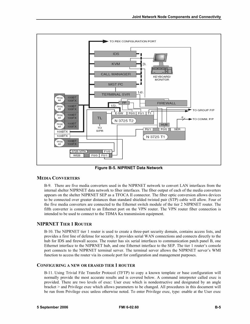
Figure B-5. NIPRNET Data Network
MEDIA CONVERTERS B-9. There are five media converters used in the NIPRNET network to convert LAN interfaces from the internal shelter NIPRNET data network to fiber interfaces. The fiber output of each of the media converters appears on the shelter NIPRNET SEP as a TFOCA II connector. The fiber optic conversion allows devices to be connected over greater distances than standard shielded twisted pair (STP) cable will allow. Four of the five media converters are connected to the Ethernet switch module of the tier 2 NIPRNET router. The fifth converter is connected to an Ethernet port on the VPN router. The VPN router fiber connection is intended to be used to connect to the TDMA Ku transmission equipment.
NIPRNET TIER 1 ROUTER B-10. The NIPRNET tier 1 router is used to create a three-part security domain, contains access lists, and provides a first line of defense for security. It provides serial WAN connections and connects directly to the hub for IDS and firewall access. The router has six serial interfaces to communication patch panel B, one Ethernet interface to the NIPRNET hub, and one Ethernet interface to the SEP. The tier 1 router’s console port connects to the NIPRNET terminal server. The terminal server allows the NIPRNET server’s WMI function to access the router via its console port for configuration and management purposes.
CONFIGURING A NEW OR ERASED TIER 1 ROUTER B-11. Using Trivial File Transfer Protocol (TFTP) to copy a known template or base configuration will normally provide the most accurate results and is covered below. A command interpreter called exec is provided. There are two levels of exec: User exec which is nondestructive and designated by an angle bracket > and Privilege exec which allows parameters to be changed. All procedures in this document will be run from Privilege exec unless otherwise noted. To enter Privilege exec, type: enable at the User exec

Appendix B
B-6 FMI 6-02.60 5 September 2006
prompt. An account and password may be required. The following user names and passwords may be encountered if the unit is in the Group A configuration (initial checkout upon delivery) and should be changed by the gaining unit: Account = jnnadmin, Password = jnn1234$. Table B-1 shows the basic steps to configure a new or erased tier 1 router.
Table B-1. Configure a Tier 1 Router
1 Connect to the router console port via the terminal server or laptop. 2 Power up router. 3 After router boots and does not find the configuration file it will want to start auto config
routine. Answer "no" to start auto config. 4 At > prompt, enter enable, press Enter, prompt should change to #. 5 Enter conf t, press Enter. Prompt changes to router (config) #. 6 Enter interface FE0/0 and press Enter. 7 Enter "ip addr xxx.xxx.xxx.xxx yyy.yyy.yyy.yyy" where x is the IP of the port and y is the
subnet mask. 8 Enter no shut, CTRL-Z. 9 Verify TFTP Server port is active. 10 Tier 2 router and firewall are already configured. Ping NIPRNET management PC once
router port FE0/0 addressed, enabled and static addresses are added to the router. 11 Verify TFTP server application is open and the server has a valid configuration file in the
TFTP_files directory. 12 Verify TFTP server application can send and receive files (under security tab: SolarWinds
TFTP Server > File > Configure > Security Tab). 13 Enter copy TFTP start from the router to start the transfer of the file to the router via the
configured interface. 14 Enter the IP of the TFTP server when the router asks for the address of the remote host. 15 When the router asks for the source file name enter the exact name of the configuration file
that is stored on the TFTP server. File names are case sensitive. 16 Enter startupconfig when the router asks for the destination filename. This should be
specified as default and is the string within the [ ] of the prompt. 17 As data is transferred,! will appear to show successful data transfer.
B-12. Table B-2 shows representative entries for the configuration of a tier 1 router. The IP addresses and description lines of the interfaces are not meant to be all inclusive. The actual entries will vary according to the mission and current policies.
Table B-2. Representative Entries for Tier 1 Router Configuration
version 12.3 service timestamps debug datetime localtime show-timezone msec service timestamps log datetime localtime show-timezone msec clock timezone GMT 0 service password-encryption no service finger no service udp-small-servers no service tcp-small-servers no ip bootp server no snmp-server no ip http server

Joint Network Node Components and Connectivity
5 September 2006 FMI 6-02.60 B-7
Table B-2. Representative Entries for Tier 1 Router Configuration
no ip source-route no service config cdp run service nagle ! Hostname_ JNN 1 ! no ip domain-lookup ip domain name jnn.army.mil ! crypto key generate rsa ! boot-start-marker boot system flash:c3725-advipservicesk9-mz.123-9.bin boot-end-marker ! logging buffered 51200 warnings ! username jnn101 password us9876# enable password us9876# enable secret us9876# ip subnet-zero ip cef ! ip multicast-routing ! no ip domain lookup ip audit po max-events 100 no ftp-server write-enable ! ! no crypto isakmp enable ! ! interface Loopback0 ip address 149.033.077.210 255.255.255.255 no ip directed-broadcast no ip proxy-arp ! interface FastEthernet0/0 description NIPR Hub Port 1 ip address 172.022.253.250 255.255.255.248 ip ospf cost 14 duplex auto speed auto no ip directed-broadcast no ip mask-reply no ip proxy-arp

Appendix B
B-8 FMI 6-02.60 5 September 2006
Table B-2. Representative Entries for Tier 1 Router Configuration
no shutdown ! interface Serial0/0 description Interface to P-400 HSD 1-0 through CPP B-A1 ip unnumbered Loopback0 ip ospf cost 22 encap ppp no shutdown no ip directed-broadcast no ip mask-reply no ip proxy-arp ! interface FastEthernet0/1 description To SEP MP2A3A1 ip address duplex auto speed auto no ip directed-broadcast no ip mask-reply no ip proxy-arp no shutdown ! interface Serial0/1 description Interface to P-400 HSD 2-0 through CPP B-A3 ip unnumbered Loopback0 no ip directed-broadcast no ip mask-reply no ip proxy-arp ip ospf cost 22 encap ppp no shutdown ! interface Serial0/2 description ip unnumbered Loopback0 ip ospf cost 22 encap ppp no shutdown no ip directed-broadcast no ip mask-reply no ip proxy-arp ! interface Serial0/3 description Interface to P-400 HSD 4-0 through CPP B-A7 ip unnumbered Loopback0 no shutdown

Joint Network Node Components and Connectivity
5 September 2006 FMI 6-02.60 B-9
Table B-2. Representative Entries for Tier 1 Router Configuration
ip ospf cost 22 encap ppp no ip directed-broadcast no ip mask-reply no ip proxy-arp ! interface Serial0/4 description Interface to KIV-19 #10 through CPP B-A16 ip unnumbered Loopback0 no shutdown pulse-time 5 ip ospf cost 22 encap ppp no ip directed-broadcast no ip mask-reply no ip proxy-arp ! interface Serial0/5 description Interface to CPP B-A17 ip unnumbered Loopback0 no shutdown ip ospf cost 22 encap ppp no ip directed-broadcast no ip mask-reply no ip proxy-arp ! router ospf 21 log-adjacency-changes network 148.022.069.209 0.0.0.0 area 0 network 172.022.253.248 000.000.000.007 area 0 ! ip classless ! ntp server 148.022.069.141 snmp-server community REAL RO snmp-server ifindex persist ! Typical configuration for the Tier 1 router to make an external BGP connection Router ospf 1 network x.x.x.x x.x.x.x area x default-information originate metric-type 1 metric 100 route-map SEND_DEFAULT_IF Router BGP XX (Your Autonomous system number) no synchronization

Appendix B
B-10 FMI 6-02.60 5 September 2006
Table B-2. Representative Entries for Tier 1 Router Configuration
redistribute ospf 1 route-map ALLOWED_ROUTES neighbor x.x.x.x remote-as XXXX (neighbor AS number) neighbor x.x.x.x route-map setMED out no auto-summary Access-list 1 permit 0.0.0.0 Access-list 2 permit x.x.x.x x.x.x.x (summary address of all subnets you want to advertise via BGP to your neighbor) Route-map SEND_DEFAULT_IF permit 10 match ip address 1 match ip next-hop x.x.x.x (your eBGP neighbor address) Route-map ALLOWED_ROUTES permit 10 match ip address 2 Route-map setMED permit 10 set metric-type internal banner motd c ATTENTION! THIS IS A DOD COMPUTER SYSTEM. BEFORE PROCESSING CLASSIFIED INFORMATION, CHECK THE SECURITY ACCREDITATION LEVEL OF THIS SYSTEM. DO NOT PROCESS, STORE OR TRANSMIT INFORMATION CLASSIFIED ABOVE ACCREDITATION LEVEL OF THIS SYSTEM. THIS COMPUTER SYSTEM, INCLUDING ALL RELATED EQUIPMENT, NETWORKS AND NETWORK DEVICES (INCLUDES INTERNET ACCESS) ARE PROVIDED ONLY FOR AUTHORIZED U.S. GOVERNMENT USE. DOD COMPUTER SYSTEMS MAY BE MONITORED FOR ALL LAWFUL PURPOSES, INCLUDING TO ENSURE THEIR USE IS AGAINST UNAUTHORIZED ACCESS, AND TO VERIFY SECURITY PROCEDURES, SURVIVABILITY, AND OPERATIONAL SECURITY. MONITORING INCLUDES, BUT IS NOT LIMITED TO, ACTIVE ATTACKS BY AUTHORIZED DOD ENTITIES TO TEST OR VERIFY THE SECURITY OF THIS SYSTEM. DURING MONITORING, INFORMATION MAY BE EXAMINED, RECORDED, COPIED, AND USED FOR AUTHORIZED PURPOSES. ALL INFORMATION, INCLUDING PERSONAL INFORMATION, PLACED ON OR SENT OVER THIS SYSTEM MAY BE MONITORED. USE OF THIS DOD COMPUTER SYSTEM, AUTHORIZED OR UNAUTHORIZED, CONSTITUTES CONSENT TO MONITORING. UNAUTHORIZED USE OF THIS DOD COMPUTER SYSTEM MAY SUBJECT YOU TO CRIMINAL PROSECUTION. EVIDENCE OF UNAUTHORIZED USE COLLECTED DURING MONITORING MAY BE USED FOR ADMINISTRATIVE, CRIMINAL OR OTHER ADVERSE ACTION. USE OF THIS SYSTEM CONSTITUTES CONSENT TO MONITORING FOR ALL LAWFUL PURPOSES. c ! line con 0 exec-timeout 5 0 login local ! line aux 0

Joint Network Node Components and Connectivity
5 September 2006 FMI 6-02.60 B-11
Table B-2. Representative Entries for Tier 1 Router Configuration
no exec exec-timeout 0 10 transport input none ! line vty 0 4 login local exec-timeout 5 0 transport input telnet ssh ! end
NIPRNET TIER 2 ROUTER B-13. The NIPRNET tier 2 router provides default gateway and routing functions for locally connected NIPRNET hosts and shelter components. It is the access point for a TACLANE that is used to tunnel through the SIPRNET data network. The router contains an Ethernet switch module used for shelter component Ethernet connections. Five Ethernet switch ports appear at the SEP. Four of those five are fiber optic converted and the fifth is a standard wire interface. The router has a T1 card that interfaces to the group patch panel. It can serve as a gateway between VoIP subscribers and the shelter PBX and can be configured to connect to the hub and firewall. The tier 2 router console port connects to the NIPRNET terminal server. The terminal server allows the NIPRNET servers WMI function to access the router via its console port for configuration and management purposes.
CONFIGURING A NEW OR ERASED TIER 2 ROUTER B-14. Using TFTP to copy a known template or base configuration will normally provide the most accurate results and is covered below. A command interpreter called exec is provided. There are two levels of exec: User exec which is nondestructive and designated by an angle bracket > and Privilege exec which allows parameters to be changed. All procedures in this document will be run from Privilege exec unless otherwise noted. To enter Privilege exec, type: enable at the User exec prompt. An account and password may be required. The following user names and passwords may be encountered if the unit is in the Group A configuration (initial checkout upon delivery) and should be changed by the gaining unit: Account = jnnadmin Password = jnn1234$. Table B-3 shows the basic steps to configure a new or erased tier 2 router.
Table B-3. Configure a Tier 2 Router
1 Connect to the router console port via the terminal server or laptop. 2 Power up router. 3 After router boots and does not find the configuration file it will want to start auto config
routine. Answer "no" to start auto config. 4 At > prompt, enter enable, press Enter, prompt should change to # 5 Enter conf t, press Enter. Prompt changes to router (config. 6 Enter interface VLAN1 and press Enter. 7 Enter "ip addr xxx.xxx.xxx.xxx yyy.yyy.yyy.yyy" where x is the IP of the port and y is the
subnet mask. 8 Enter no shut, CTRL-Z. 9 Verify TFTP Server port is active. 10 Verify TFTP server application is open and the server has a valid configuration file in the
TFTP_files directory.

Appendix B
B-12 FMI 6-02.60 5 September 2006
Table B-3. Configure a Tier 2 Router
11 Verify TFTP server application can send and receive files (under security tab: SolarWinds TFTP Server > File > Configure > Security Tab).
12 Enter copy TFTP start from the router to start the transfer of the file to the router via the configured interface.
13 Enter the IP of the TFTP server when the router asks for the address of the remote host. 14 When the router asks for the source file name enter the exact name of the configuration file
that is stored on the TFTP server. File names are case sensitive. 15 Enter startupconfig when the router asks for the destination filename. This should be
specified as default and is the string within the [ ] of the prompt. 16 As data is transferred, ! will appear to show successful data transfer.
B-15. Table B-4 shows representative entries for the configuration of a tier 2 router. The IP addresses and description lines of the interfaces are not meant to be all inclusive. The actual entries will vary according to the mission.
Table B-4. Representative Entries for Tier 2 Router Configuration
version 12.3 service timestamps debug datetime localtime show-timezone msec service timestamps log datetime localtime show-timezone msec clock timezone GMT 0 service password-encryption no service finger no service udp-small-servers no service tcp-small-servers no ip bootp server no snmp-server no ip http server no ip source-route no service config no cdp run service nagle ! hostname JNN NTR2 ! no ip domain-lookup ip domain name jnn.army.mil ! boot-start-marker boot system flash:c3725-advipservicesk9-mz.123-9.bin boot-end-marker ! logging buffered 51200 warnings ! username jnn101 password us9876# enable secret us9876# ! no network-clock-participate slot 1

Joint Network Node Components and Connectivity
5 September 2006 FMI 6-02.60 B-13
Table B-4. Representative Entries for Tier 2 Router Configuration
voice-card 1 dspfarm ! no aaa new-model ip subnet-zero ip cef ! ip multicast-routing ! ip dhcp excluded-address Insert IP Range ! ip dhcp pool data network Insert IP Address and Subnet Mask default-router Insert IP Address ! ip audit po max-events 100 no ftp-server write-enable ! controller T1 1/0 framing esf linecode b8zs ds0-group 0 timeslots 1-24 type e&m-wink-start ! controller T1 1/1 framing esf linecode b8zs ds0-group 0 timeslots 1-24 type e&m-wink-start ! no crypto isakmp enable ! interface Loopback0 ip address Insert IP Address and Subnet Mask no ip directed-broadcast no ip proxy-arp ! interface FastEthernet0/0 description Interface to Tier 1 IA Panel Router ip address Insert IP Address and Subnet Mask duplex auto speed auto no ip directed-broadcast no ip mask-reply no ip proxy-arp no shutdown !

Appendix B
B-14 FMI 6-02.60 5 September 2006
Table B-4. Representative Entries for Tier 2 Router Configuration
interface FastEthernet0/1 no ip address duplex auto speed auto no ip directed-broadcast no ip mask-reply no ip proxy-arp no shutdown ! interface FastEthernet2/0 description Interface to CM switchport access vlan 58 no ip address no ip proxy-arp no shutdown ! interface FastEthernet2/1 description Interface to MGT PC no ip address no shutdown ! interface FastEthernet2/2 description Interface to KVM no ip address no shutdown ! interface FastEthernet2/3 description Interface to Terminal Server no ip address no shutdown ! interface FastEthernet2/4 description Interface to Redcom no ip address no shutdown ! interface FastEthernet2/5 description Interface to VPN (Future Use) no ip address shutdown ! interface FastEthernet2/6 description Interface to IDS no ip address no shutdown

Joint Network Node Components and Connectivity
5 September 2006 FMI 6-02.60 B-15
Table B-4. Representative Entries for Tier 2 Router Configuration
! interface FastEthernet2/7 description Trunk to Voice Case switchport trunk allowed vlan 1,2,58,1002-1005 switchport mode trunk no ip address no shutdown ! interface FastEthernet2/8 description Trunk to Data case switchport access vlan 59 switchport trunk allowed vlan 1,2,59,1002-1005 switchport mode trunk no ip address no shutdown ! interface FastEthernet2/9 description Interface to SEP MC3 no ip address no shutdown ! interface FastEthernet2/10 description Interface to SEP MC4 no ip address duplex full speed 100 no shutdown ! interface FastEthernet2/11 description Interface to SEP no ip address no shutdown ! interface FastEthernet2/12 description Interface to IA Patch no ip address shutdown ! interface FastEthernet2/13 description Interface to VPN router switchport access vlan 67 no ip address no shutdown ! interface FastEthernet2/14

Appendix B
B-16 FMI 6-02.60 5 September 2006
Table B-4. Representative Entries for Tier 2 Router Configuration
description Interface to Taclane2 PT no ip address shutdown ! interface FastEthernet2/15 description Interface to GPS NTP Port no ip address no shutdown ! interface Vlan1 ip address Insert IP Address and Subnet Mask no ip directed-broadcast no ip mask-reply no ip proxy-arp no shutdown ! interface Vlan58 ip address Insert IP Address and Subnet Mask no ip directed-broadcast no ip mask-reply no ip proxy-arp no shutdown ! interface Vlan59 description Vlan for NIPR data case ip address Insert IP Address and Subnet Mask no ip directed-broadcast no ip mask-reply no ip proxy-arp no shutdown ! interface Vlan67 description Interface to VPN Router ip address Insert IP Address and Subnet Mask no ip directed-broadcast no ip mask-reply no ip proxy-arp no shutdown ! router ospf 21 log-adjacency-changes network Insert Network and Inverse Mask area 0 network Insert Network and Inverse Mask area 0 ! FastEthernet 0/0 ! ip classless !

Joint Network Node Components and Connectivity
5 September 2006 FMI 6-02.60 B-17
Table B-4. Representative Entries for Tier 2 Router Configuration
snmp-server community Insert Community String RO snmp-server enable traps tty banner motd _C ATTENTION! THIS IS A DOD COMPUTER SYSTEM. BEFORE PROCESSING CLASSIFIED INFORMATION, CHECK THE SECURITY ACCREDITATION LEVEL OF THIS SYSTEM. DO NOT PROCESS, STORE OR TRANSMIT INFORMATION CLASSIFIED ABOVE ACCREDITATION LEVEL OF THIS SYSTEM. THIS COMPUTER SYSTEM, INCLUDING ALL RELATED EQUIPMENT, NETWORKS AND NETWORK DEVICES (INCLUDES INTERNET ACCESS) ARE PROVIDED ONLY FOR AUTHORIZED U.S. GOVERNMENT USE. DOD COMPUTER SYSTEMS MAY BE MONITORED FOR ALL LAWFUL PURPOSES, INCLUDING TO ENSURE THEIR USE IS AGAINST UNAUTHORIZED ACCESS, AND TO VERIFY SECURITY PROCEDURES, SURVIVABILITY, AND OPERATIONAL SECURITY. MONITORING INCLUDES, BUT IS NOT LIMITED TO, ACTIVE ATTACKS BY AUTHORIZED DOD ENTITIES TO TEST OR VERIFY THE SECURITY OF THIS SYSTEM. DURING MONITORING, INFORMATION MAY BE EXAMINED, RECORDED, COPIED, AND USED FOR AUTHORIZED PURPOSES. ALL INFORMATION, INCLUDING PERSONAL INFORMATION, PLACED ON OR SENT OVER THIS SYSTEM MAY BE MONITORED. USE OF THIS DOD COMPUTER SYSTEM, AUTHORIZED OR UNAUTHORIZED, CONSTITUTES CONSENT TO MONITORING. UNAUTHORIZED USE OF THIS DOD COMPUTER SYSTEM MAY SUBJECT YOU TO CRIMINAL PROSECUTION. EVIDENCE OF UNAUTHORIZED USE COLLECTED DURING MONITORING MAY BE USED FOR ADMINISTRATIVE, CRIMINAL OR OTHER ADVERSE ACTION. USE OF THIS SYSTEM CONSTITUTES CONSENT TO MONITORING FOR ALL LAWFUL PURPOSES. _ ! voice-port 1/0:0 timeouts interdigit 2 ! voice-port 1/1:0 ! dial-peer voice 1 voip destination-pattern 6700… session target ipv4: Insert IP Address ! dial-peer voice 2 pots destination-pattern .T port 1/0:0 ! gateway ! ntp server Insert IP Address banner motd c ATTENTION! THIS IS A DOD COMPUTER SYSTEM. BEFORE PROCESSING CLASSIFIED INFORMATION, CHECK THE SECURITY ACCREDITATION LEVEL OF THIS SYSTEM. DO NOT PROCESS, STORE OR TRANSMIT INFORMATION CLASSIFIED ABOVE ACCREDITATION LEVEL OF THIS SYSTEM. THIS COMPUTER SYSTEM, INCLUDING ALL RELATED EQUIPMENT, NETWORKS AND NETWORK DEVICES (INCLUDES INTERNET ACCESS) ARE PROVIDED ONLY FOR

Appendix B
B-18 FMI 6-02.60 5 September 2006
Table B-4. Representative Entries for Tier 2 Router Configuration
AUTHORIZED U.S. GOVERNMENT USE. DOD COMPUTER SYSTEMS MAY BE MONITORED FOR ALL LAWFUL PURPOSES, INCLUDING TO ENSURE THEIR USE IS AGAINST UNAUTHORIZED ACCESS, AND TO VERIFY SECURITY PROCEDURES, SURVIVABILITY, AND OPERATIONAL SECURITY. MONITORING INCLUDES, BUT IS NOT LIMITED TO, ACTIVE ATTACKS BY AUTHORIZED DOD ENTITIES TO TEST OR VERIFY THE SECURITY OF THIS SYSTEM. DURING MONITORING, INFORMATION MAY BE EXAMINED, RECORDED, COPIED, AND USED FOR AUTHORIZED PURPOSES. ALL INFORMATION, INCLUDING PERSONAL INFORMATION, PLACED ON OR SENT OVER THIS SYSTEM MAY BE MONITORED. USE OF THIS DOD COMPUTER SYSTEM, AUTHORIZED OR UNAUTHORIZED, CONSTITUTES CONSENT TO MONITORING. UNAUTHORIZED USE OF THIS DOD COMPUTER SYSTEM MAY SUBJECT YOU TO CRIMINAL PROSECUTION. EVIDENCE OF UNAUTHORIZED USE COLLECTED DURING MONITORING MAY BE USED FOR ADMINISTRATIVE, CRIMINAL OR OTHER ADVERSE ACTION. USE OF THIS SYSTEM CONSTITUTES CONSENT TO MONITORING FOR ALL LAWFUL PURPOSES. c ! line con 0 exec-timeout 5 0 login local ! line aux 0 no exec exec-timeout 0 10
NIPRNET VIRTUAL PRIVATE NETWORK (VPN) ROUTER B-16. The NIPRNET VPN router is used to establish VPN links via the Ku TDMA network to the CPN, UHN, and other JNN shelters. The VPN links are Advanced Encryption Standard (AES) encrypted. The VPN router is configured as the Certificate Authority Server to support the encryption system. The VPN router is populated and configured to use a web cache module. (Note the Web Cache function is independent of its other VPN and IP security functions.) The router has Ethernet connectivity to the NIPRNET tier 2 router Ethernet switch module, the cipher text port of the TACLANE, and the SEP. The purpose of the NIPRNET router interface is to allow NIPRNET data connectivity to access the VPN networks. The TACLANE interface allows SIPRNET traffic to tunnel through the VPN Ku TDMA network. The SEP interface is fiber optic modulated for connection to the external Ku TDMA transmission equipment.
CONFIGURING A NEW OR ERASED VPN ROUTER B-17. Using TFTP to copy a known template or base configuration will normally provide the most accurate results and is covered below. A command interpreter called exec is provided. There are two levels of exec: User exec which is nondestructive and designated by an angle bracket > and Privilege exec which allows parameters to be changed. All procedures in this document will be run from Privilege exec unless otherwise noted. To enter Privilege exec, type: enable at the User exec prompt. An account and password may be required. The following user names and passwords may be encountered if the unit is in the Group A configuration (initial checkout upon delivery) and should be changed by the gaining unit: Account = jnnadmin Password = jnn1234$. Table B-5 shows the basic steps to configure a new or erased VPN router.
Table B-5. Configure a VPN Router
1 Connect to the router console port via the terminal server or laptop. 2 Power up router.

Joint Network Node Components and Connectivity
5 September 2006 FMI 6-02.60 B-19
Table B-5. Configure a VPN Router
3 After router boots and does not find the configuration file it will want to start auto config routine. Answer "no" to start auto config.
4 At > prompt, enter enable, press Enter, prompt should change to #. 5 Enter conf t, press Enter. Prompt changes to router(config)#. 6 Enter interface FE0/0 and press Enter. 7 Enter "ip addr xxx.xxx.xxx.xxx yyy.yyy.yyy.yyy" where x is the IP of the port and y is the
subnet mask. 8 Enter no shut, CTRL-Z. 9 Verify TFTP Server port is active. 10 Tier 2 router is already configured. Ping NIPRNET management PC once router port FE0/1
addressed and enabled. 11 Verify TFTP server application is open and the server has a valid configuration file in the
TFTP_files directory. 12 Verify TFTP server application can send and receive files (under security tab: SolarWinds
TFTP Server > File > Configure > Security Tab). 13 Enter copy TFTP start from the router to start the transfer of the file to the router via the
configured interface. 14 Enter the IP of the TFTP server when the router asks for the address of the remote host. 15 When the router asks for the source file name enter the exact name of the configuration file
that is stored on the TFTP server. File names are case sensitive. 16 Enter startupconfig when the router asks for the destination filename. This should be
specified as default and is the string within the [ ] of the prompt. 17 As data is transferred, ! will appear to show successful data transfer.
B-18. Table B-6 shows representative entries for the configuration of a VPN router. The IP addresses and description lines of the interfaces are not meant to be all inclusive. The actual entries will vary according to the mission.
Table B-6. Representative Entries for a VPN Router Configuration
version 12.3 service timestamps debug datetime localtime show-timezone msec service timestamps log datetime localtime show-timezone msec clock timezone GMT 0 service password-encryption no service finger no service udp-small-servers no service tcp-small-servers no ip bootp server no snmp-server no ip http server no ip source-route no service config no cdp run service nagle ! hostname Insert Hostname _BVR

Appendix B
B-20 FMI 6-02.60 5 September 2006
Table B-6. Representative Entries for a VPN Router Configuration
! boot-start-marker boot system flash:c3725-advipservicesk9-mz.123-9.bin boot-end-marker ! username Insert username for JNN Operators privilege 5 password Insert user password username Insert username for JNN Administrators privilege 5 password Insert admin password enable secret Insert enable secret password no network-clock-participate slot 2 no aaa new-model ip subnet-zero ip cef ! no ip domain-lookup ip domain name Insert Domain name ! ip audit po max-events 100 no ftp-server write-enable ip multicast-routing ! class-map match-all SIPRdata match dscp af21 class-map match-all SIPRvoiceSig match dscp af31 class-map match-all SIPRvoice match dscp ef class-map match-all Routing match dscp cs6 class-map match-any Linkway match class-map SIPRdata match class-map SIPRvoiceSig match class-map SIPRvoice match class-map Routing match class-map class-default ! ! policy-map Aggregate class SIPRvoice priority percent 40 class SIPRvoiceSig bandwidth remaining percent 3 class Routing bandwidth remaining percent 2 class SIPRdata bandwidth remaining percent 30

Joint Network Node Components and Connectivity
5 September 2006 FMI 6-02.60 B-21
Table B-6. Representative Entries for a VPN Router Configuration
class class-default fair-queue policy-map Linkway class Linkway shape average 4096000 service-policy Aggregate ! crypto isakmp policy 10 ! encr aes authentication pre-share crypto isakmp key Insert Key address Insert IP Address and Subnet Mask ! crypto isakmp keepalive 60 10 ! ! crypto ipsec transform-set aes_set esp-aes 256 esp-md5-hmac mode transport ! crypto ipsec profile jnn set transform-set aes_set ! interface Loopback0 ip address Insert IP Address and Subnet Mask no ip directed-broadcast no ip proxy-arp ! interface Tunnel1 description DMVPN Multipoint Hub to BN Spokes ip address Insert IP Address and Subnet Mask no ip redirects ip mtu 1420 ip nhrp authentication Insert Key ip nhrp map multicast dynamic ip nhrp map multicast Insert IP Address ip nhrp map 1 Insert IP Address Insert IP Address ip nhrp network-id Insert net id ip nhrp holdtime 600 ip nhrp nhs Insert IP Address ip ospf network broadcast bandwidth 4096 ip ospf priority 2 tunnel source FastEthernet2/0 tunnel mode gre multipoint tunnel key Insert Key tunnel protection ipsec profile jnn no ip directed-broadcast no ip mask-reply
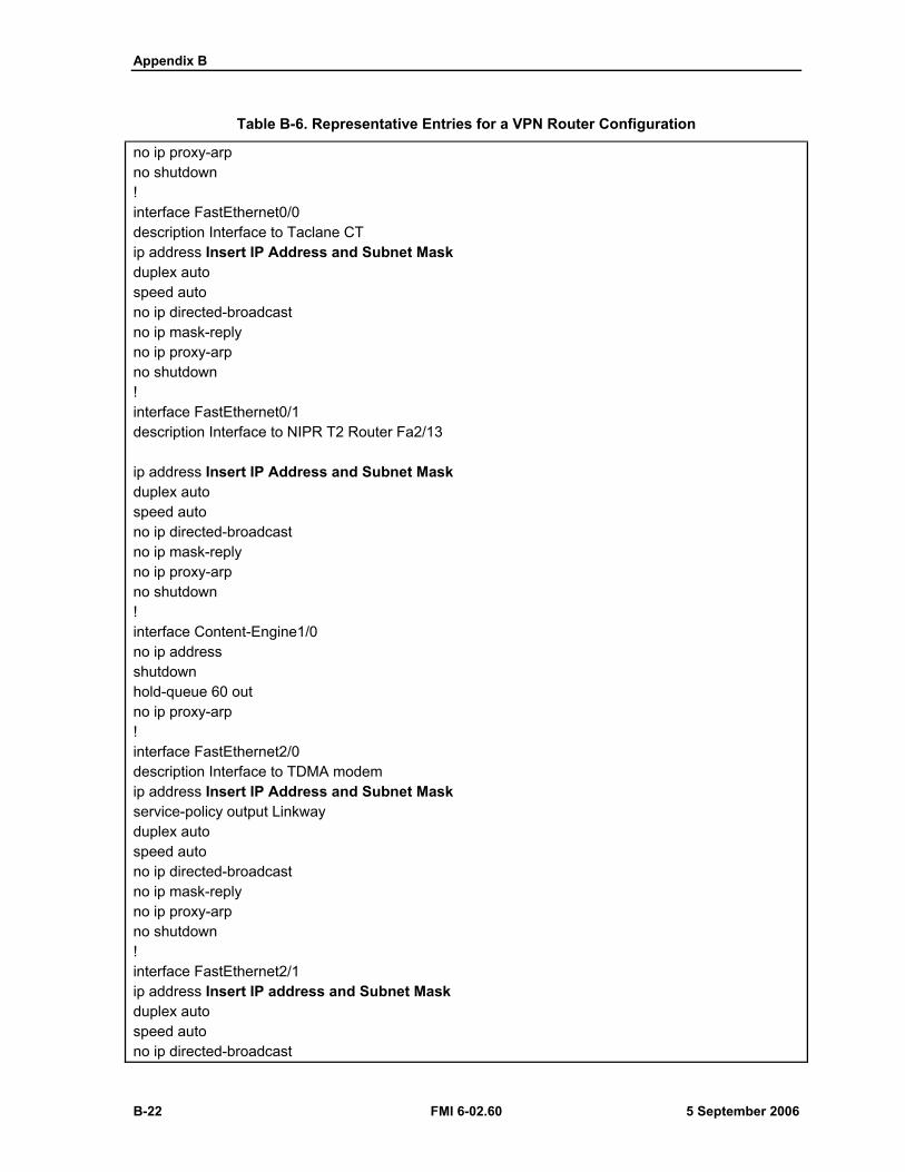
Appendix B
B-22 FMI 6-02.60 5 September 2006
Table B-6. Representative Entries for a VPN Router Configuration
no ip proxy-arp no shutdown ! interface FastEthernet0/0 description Interface to Taclane CT ip address Insert IP Address and Subnet Mask duplex auto speed auto no ip directed-broadcast no ip mask-reply no ip proxy-arp no shutdown ! interface FastEthernet0/1 description Interface to NIPR T2 Router Fa2/13 ip address Insert IP Address and Subnet Mask duplex auto speed auto no ip directed-broadcast no ip mask-reply no ip proxy-arp no shutdown ! interface Content-Engine1/0 no ip address shutdown hold-queue 60 out no ip proxy-arp ! interface FastEthernet2/0 description Interface to TDMA modem ip address Insert IP Address and Subnet Mask service-policy output Linkway duplex auto speed auto no ip directed-broadcast no ip mask-reply no ip proxy-arp no shutdown ! interface FastEthernet2/1 ip address Insert IP address and Subnet Mask duplex auto speed auto no ip directed-broadcast

Joint Network Node Components and Connectivity
5 September 2006 FMI 6-02.60 B-23
Table B-6. Representative Entries for a VPN Router Configuration
no ip mask-reply no ip proxy-arp shutdown ! router ospf 21 log-adjacency-changes network Insert Network and Inverse Mask area 0 passive-interface FastEthernet2/0 ! router rip version 2 network Insert Network Address ! log-adjacency-changes ip classless ip http server no ip http secure-server ntp server Insert IP Address ! snmp-server community Insert Community String RO banner motd c ATTENTION! THIS IS A DOD COMPUTER SYSTEM. BEFORE PROCESSING CLASSIFIED INFORMATION, CHECK THE SECURITY ACCREDITATION LEVEL OF THIS SYSTEM. DO NOT PROCESS, STORE OR TRANSMIT INFORMATION CLASSIFIED ABOVE ACCREDITATION LEVEL OF THIS SYSTEM. THIS COMPUTER SYSTEM, INCLUDING ALL RELATED EQUIPMENT, NETWORKS AND NETWORK DEVICES (INCLUDES INTERNET ACCESS) ARE PROVIDED ONLY FOR AUTHORIZED U.S. GOVERNMENT USE. DOD COMPUTER SYSTEMS MAY BE MONITORED FOR ALL LAWFUL PURPOSES, INCLUDING TO ENSURE THEIR USE IS AGAINST UNAUTHORIZED ACCESS, AND TO VERIFY SECURITY PROCEDURES, SURVIVABILITY, AND OPERATIONAL SECURITY. MONITORING INCLUDES, BUT IS NOT LIMITED TO, ACTIVE ATTACKS BY AUTHORIZED DOD ENTITIES TO TEST OR VERIFY THE SECURITY OF THIS SYSTEM. DURING MONITORING, INFORMATION MAY BE EXAMINED, RECORDED, COPIED, AND USED FOR AUTHORIZED PURPOSES. ALL INFORMATION, INCLUDING PERSONAL INFORMATION, PLACED ON OR SENT OVER THIS SYSTEM MAY BE MONITORED. USE OF THIS DOD COMPUTER SYSTEM, AUTHORIZED OR UNAUTHORIZED, CONSTITUTES CONSENT TO MONITORING. UNAUTHORIZED USE OF THIS DOD COMPUTER SYSTEM MAY SUBJECT YOU TO CRIMINAL PROSECUTION. EVIDENCE OF UNAUTHORIZED USE COLLECTED DURING MONITORING MAY BE USED FOR ADMINISTRATIVE, CRIMINAL OR OTHER ADVERSE ACTION. USE OF THIS SYSTEM CONSTITUTES CONSENT TO MONITORING FOR ALL LAWFUL PURPOSES. c ! line con 0 exec-timeout 5 0 login local ! line aux 0

Appendix B
B-24 FMI 6-02.60 5 September 2006
Table B-6. Representative Entries for a VPN Router Configuration
no exec exec-timeout 0 10 transport input none ! line vty 0 4 login local exec-timeout 5 0 transport input telnet ssh ! end
NIPRNET FIREWALL B-19. The NIPRNET data network contains a firewall. The firewall can be positioned either between the tier 1 and tier 2 router, or between the tier 2 router and its Ethernet switch module. The firewall forms a boundary between the protected (inside) and unprotected (outside) networks. All JNN traffic between the protected and unprotected networks flows through the JNN firewall to maintain security. The firewall is locally managed via the security domain’s server. The firewall has a console port interface to the terminal server for configuration. It has two Ethernet connections to the IA config panel.
CONFIGURING A FIREWALL B-20. The firewall is preconfigured with a default configuration. The JNN operators will receive updated firewall configurations and policies from the NETOPS cell. The following procedures can be used to monitor and download precreated configurations on the firewall. The IP addresses shown are examples only. Table B-7 shows the steps for connecting the device to a network and configuring the firewall using a vt100 Terminal Emulator or Telnet.
Table B-7. Connecting and Configuring Firewall
1 Ensure the power switch is off. 2 Connect the power cable to the power outlet at the rear of the device and to a power source. 3 Connect a RJ-45 cross-over cable from trust zone interface (Ethernet port 1) to internal
switch, router or hub. 4 Connect a RJ-45 straight-through cable from untrust zone interface (Ethernet port 3) to
external router. 5 Flip power switch to on position. 6 Power LED glows green, Status-1 LED blinks green and Ethernet port LEDs for each
connected interface glow or blink green. There are two ways to establish a console session with the firewall after connecting: vt100 Terminal Emulator through a RJ-45 serial cable connected to the console port or using Telnet through a TCP/IP network connection. To establish a connection using a vt100 Terminal Emulator: 1 Connect a RJ-45 serial cable between the console port on the firewall and serial port on your
computer. 2 Press ENTER for login prompt. 3 At Username prompt, type: netscreen.

Joint Network Node Components and Connectivity
5 September 2006 FMI 6-02.60 B-25
B-21. The default IP address for managing the firewall through the Trust zone interface (Ethernet port 1) is 192.68.1.1. This is the IP address used to manage the device through a Telnet session or with the WebUI management application. If a different IP address is used, it needs to be assigned. Table B-8 shows the steps to set the IP address of the Trust zone interface.
Table B-8. Set IP Address
1 Choose an unused IP address within the current address range of the Local Area Network. 2 Enter set interface ethernet1 ip ip_addr/mask. 3 To confirm new port settings enter get interface. 4 Observe that the IP address for the Trust zone interface is one set.
B-22. Table B-9 shows the steps to connect using Telnet.
Table B-9. Connect Using TELNET
1 Connect a RJ-45 cross-over cable from Trustzone interface (Ethernet port 1) on the firewall to internal switch, router or Hub in the LAN.
2 Open a Telnet session to 192.168.1.1 3 At Username prompt, type: netscreen 4 At Password prompt, type: netscreen
Allowing Outbound Traffic B-23. By default, the firewall does not allow inbound or outbound traffic. Access policies must be created to permit specific kinds of traffic in the directions needed. Access policies to deny and tunnel traffic can also be created. Configuration of the firewall and access policies is accomplished based on current policies and the guidance currently in effect.
B-24. The Outgoing Policy Wizard in the WebUI management application may also be used to create access policies for outbound traffic. Table B-10 shows the steps to access the device with the WebUI management application.
Table B-10. Connect Using WebUI
1 Connect your computer to the Trust zone interface (Ethernet port 1). 2 Launch the browser , enter the IP address of the Trust zone interface in the URL field and
press enter. 3 Observe the Netscreen WebUI software displays login prompt. 4 Enter netscreen in the Admin Name field. 5 Enter netscreen in the Password field. 6 Click Login. 7 The NetScreen WebUI application window appears and configurations may be downloaded
or uploaded.
B-25. Table B-11 shows representative entries for the configuration of a firewall. The IP addresses and description lines of the interfaces are not meant to be all inclusive. The actual entries will vary according to the mission and current policies.
Table B-11. Representative Entries for a JNN Firewall Configuration
set clock ntp set clock timezone 0 set vrouter trust-vr sharable unset vrouter "trust-vr" auto-route-export

Appendix B
B-26 FMI 6-02.60 5 September 2006
Table B-11. Representative Entries for a JNN Firewall Configuration
id 0 set auth-server "Local" set auth-server "Local" server-name “Local” set auth default auth server "Local" set admin name gdadmin set admin password gd1234$gd1234$ set admin auth timeout 10 set admin auth server "Local" set admin auth banner secondary "This computer system, including all related equipment, networks and network devices (specifically including Internet access) are provided only for authorized U. S. Government use. DoD computer systems may be monitored for all lawful purposes, to ensure that their use is authorized, for management of the system, to facilitate protection against unauthorized access, and to verify security procedures, survivability and operational security. Monitoring includes active attacks by authorized DoD entities to test or verify security of this system. During monitoring, information may be examined, recorded, copied and used for authorized purposes. All information, including personal information, placed on or sent over this system may be monitored. Use of thisDoD computer system, authorized or unauthorized, constitutes consent to monitoring of this system. Unauthorized use may subject you to criminal prosecution. Evidence of unauthorized use collected during monitoring collected during monitoring may be used for administrative, criminal or adverse action. Use of this system constitutes consent to monitoring for these purposes." set admin auth banner telnet login "This is a Department of Defense computer system." set admin auth banner console login "This is a Department of Defense computer system." set admin format dos set zone "Trust" vrouter "trust-vr" set zone “Untrust” vrouter "trust-vr" set zone “DMZ” vrouter “trust-vr" set zone “VLAN” vrouter “trust-vr” set zone “Trust” tcp-rst set zone "Untrust" block unset zone "Untrust" tcp-rst set zone”MGT” block set zone “DMZ” tcp-rst set zone “VLAN” block set zone "VLAN" tcp-rst set zone “Untrust” screen tear-drop set zone "Untrust" screen syn-flood set zone "Untrust" screen ping-death set zone "Untrust" screen ip-filter-src set zone "Untrust" screen land set zone “V1-Untrust" screen tear-drop set zone “V 1-Untrust" screen syn-flood set zone “V 1-Untrust" screen ping-death set zone “V 1-Untrust" screen ip-filter-src set zone “V 1-Untrust" screen land set interface ethernet1 phy full 100mb set interface ethernet2 phy full 100m set interface ethernet 3 phy half 100

Joint Network Node Components and Connectivity
5 September 2006 FMI 6-02.60 B-27
Table B-11. Representative Entries for a JNN Firewall Configuration
set interface ethernet4 phy full 100mb set interface "ethernet1" zone "V1-Trust" set interface "ethernet2" zone "Null" set interface "ethernet3" zone "V1-Untrust” set interface vlan1 ip unset interface vlan1 bypass-others-ipsec set vlan1 bypass-non-ip set interface vlan1 ip manageable set interface vlan1 broadcast arp unset interface vlan1 manage telnet set interface vlan1 ip m set interface vlan1 broadcast unset interface vlan1 manage telnet unset interface vlan1 manage snmp unset interface vlan1 manage ssl unset interface vlan1 manage web unset zone V1-Trust manage telnet unset zone V1-Trust manage snmp unset zone V1-Trust manage ssl unset zone V1-Trust manage web set zone V1-Trust manage ping set zone V1-Trust manage ssh set zone V1-Untrust manage ping set zone V1-Untrust manage ssh unset flow no-tcp-seq-check set flow tcp-syn-check set console timeout 5 set hostname JNN_ set ike respond-bad-spi 1 set pki authority default scep mode "auto" set pki x509 default cert-path partial set url protocol sc-cpa exit set policy id 1 from "V1-Trust" to "V1-Untrust" "Any" "Any" "ANY" permit log set policy id 2 from "V1-Untrust" to "V1-Trust" "Any" "Any" "ANY" permit log set alarm threshold CPU 90 set alarm threshold session percent 80 set firewall log-self set nsmgmt bulkcli reboot-timeout 60 set ssh version v2 set ssh enable set config lock timeout 5 set dl-buf size 4718592 set ntp server 144.104.1 set ntp interval 20 set snmp port listen 161
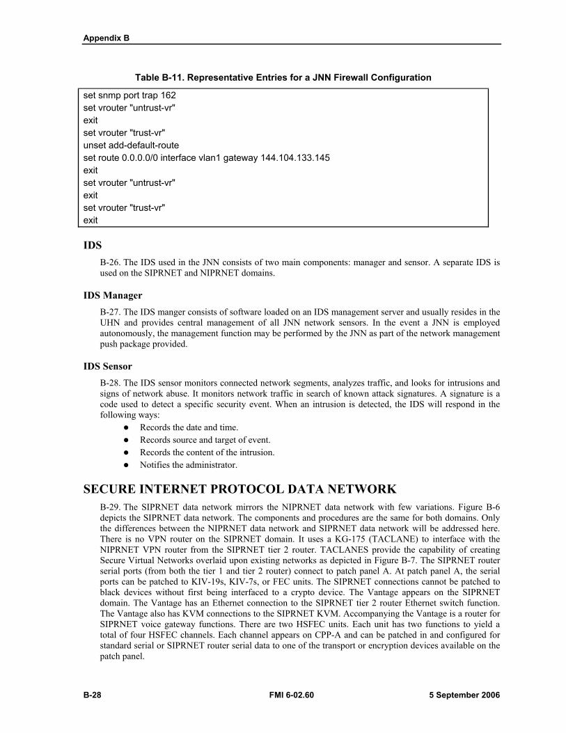
Appendix B
B-28 FMI 6-02.60 5 September 2006
Table B-11. Representative Entries for a JNN Firewall Configuration
set snmp port trap 162 set vrouter "untrust-vr" exit set vrouter "trust-vr" unset add-default-route set route 0.0.0.0/0 interface vlan1 gateway 144.104.133.145 exit set vrouter "untrust-vr" exit set vrouter "trust-vr" exit
IDS B-26. The IDS used in the JNN consists of two main components: manager and sensor. A separate IDS is used on the SIPRNET and NIPRNET domains.
IDS Manager B-27. The IDS manger consists of software loaded on an IDS management server and usually resides in the UHN and provides central management of all JNN network sensors. In the event a JNN is employed autonomously, the management function may be performed by the JNN as part of the network management push package provided.
IDS Sensor B-28. The IDS sensor monitors connected network segments, analyzes traffic, and looks for intrusions and signs of network abuse. It monitors network traffic in search of known attack signatures. A signature is a code used to detect a specific security event. When an intrusion is detected, the IDS will respond in the following ways:
Records the date and time. Records source and target of event. Records the content of the intrusion. Notifies the administrator.
SECURE INTERNET PROTOCOL DATA NETWORK B-29. The SIPRNET data network mirrors the NIPRNET data network with few variations. Figure B-6 depicts the SIPRNET data network. The components and procedures are the same for both domains. Only the differences between the NIPRNET data network and SIPRNET data network will be addressed here. There is no VPN router on the SIPRNET domain. It uses a KG-175 (TACLANE) to interface with the NIPRNET VPN router from the SIPRNET tier 2 router. TACLANES provide the capability of creating Secure Virtual Networks overlaid upon existing networks as depicted in Figure B-7. The SIPRNET router serial ports (from both the tier 1 and tier 2 router) connect to patch panel A. At patch panel A, the serial ports can be patched to KIV-19s, KIV-7s, or FEC units. The SIPRNET connections cannot be patched to black devices without first being interfaced to a crypto device. The Vantage appears on the SIPRNET domain. The Vantage has an Ethernet connection to the SIPRNET tier 2 router Ethernet switch function. The Vantage also has KVM connections to the SIPRNET KVM. Accompanying the Vantage is a router for SIPRNET voice gateway functions. There are two HSFEC units. Each unit has two functions to yield a total of four HSFEC channels. Each channel appears on CPP-A and can be patched in and configured for standard serial or SIPRNET router serial data to one of the transport or encryption devices available on the patch panel.
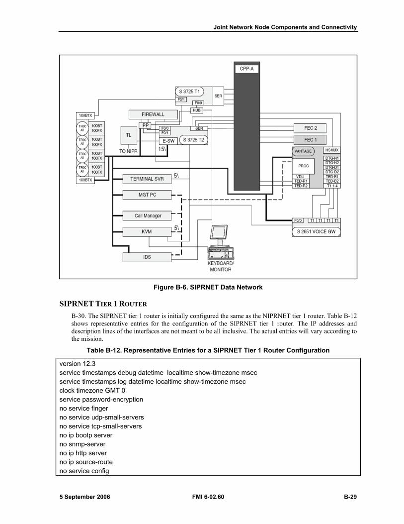
Joint Network Node Components and Connectivity
5 September 2006 FMI 6-02.60 B-29
Figure B-6. SIPRNET Data Network
SIPRNET TIER 1 ROUTER B-30. The SIPRNET tier 1 router is initially configured the same as the NIPRNET tier 1 router. Table B-12 shows representative entries for the configuration of the SIPRNET tier 1 router. The IP addresses and description lines of the interfaces are not meant to be all inclusive. The actual entries will vary according to the mission.
Table B-12. Representative Entries for a SIPRNET Tier 1 Router Configuration
version 12.3 service timestamps debug datetime localtime show-timezone msec service timestamps log datetime localtime show-timezone msec clock timezone GMT 0 service password-encryption no service finger no service udp-small-servers no service tcp-small-servers no ip bootp server no snmp-server no ip http server no ip source-route no service config
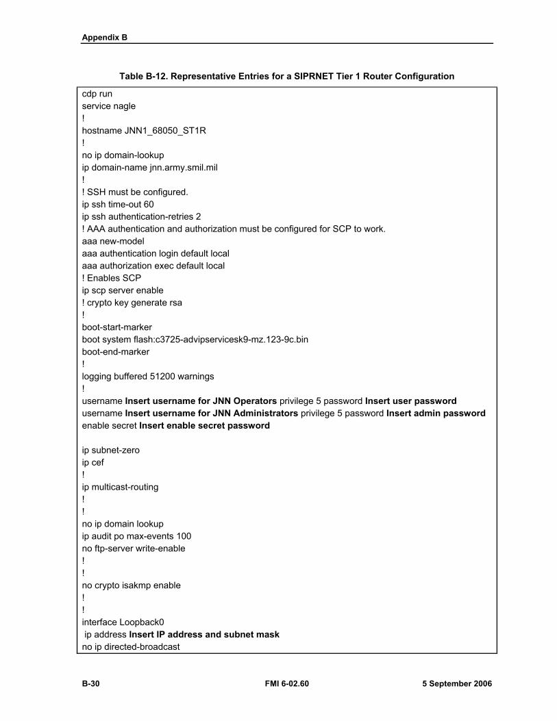
Appendix B
B-30 FMI 6-02.60 5 September 2006
Table B-12. Representative Entries for a SIPRNET Tier 1 Router Configuration
cdp run service nagle ! hostname JNN1_68050_ST1R ! no ip domain-lookup ip domain-name jnn.army.smil.mil ! ! SSH must be configured. ip ssh time-out 60 ip ssh authentication-retries 2 ! AAA authentication and authorization must be configured for SCP to work. aaa new-model aaa authentication login default local aaa authorization exec default local ! Enables SCP ip scp server enable ! crypto key generate rsa ! boot-start-marker boot system flash:c3725-advipservicesk9-mz.123-9c.bin boot-end-marker ! logging buffered 51200 warnings ! username Insert username for JNN Operators privilege 5 password Insert user password username Insert username for JNN Administrators privilege 5 password Insert admin password enable secret Insert enable secret password ip subnet-zero ip cef ! ip multicast-routing ! ! no ip domain lookup ip audit po max-events 100 no ftp-server write-enable ! ! no crypto isakmp enable ! ! interface Loopback0 ip address Insert IP address and subnet mask no ip directed-broadcast

Joint Network Node Components and Connectivity
5 September 2006 FMI 6-02.60 B-31
Table B-12. Representative Entries for a SIPRNET Tier 1 Router Configuration
no ip proxy-arp ! interface FastEthernet0/0 description SIPR Hub Port1 ip address Insert IP address and subnet mask ip pim sparse-mode ip ospf cost 14 duplex half speed auto no ip directed-broadcast no ip mask-reply no ip proxy-arp no shutdown ! interface Serial0/0 description Interface to KIV-19 #3 through CPP A-A1 no ip address ip pim sparse-mode no shutdown pulse-time 5 ip ospf cost 22 encap ppp no ip directed-broadcast no ip mask-reply no ip proxy-arp ! interface FastEthernet0/1 description To SEP MP1A1A1 ip address ! ! ip pim sparse-mode duplex auto speed auto no ip directed-broadcast no ip mask-reply no ip proxy-arp shutdown ! interface Serial0/1 description Interface to KIV-19 #4 through CPP A-A2 ip unnumbered Loopback0 ip pim sparse-mode no shutdown pulse-time 5 ip ospf cost 22 encap ppp no ip directed-broadcast

Appendix B
B-32 FMI 6-02.60 5 September 2006
Table B-12. Representative Entries for a SIPRNET Tier 1 Router Configuration
no ip mask-reply no ip proxy-arp ! interface Serial0/2 description Interface to FEC 1-1 through CPP A-A3 ip unnumbered Loopback0 ip pim sparse-mode no shutdown pulse-time 5 ip ospf cost 22 encap ppp no ip directed-broadcast no ip mask-reply no ip proxy-arp ! interface Serial0/3 description Interface to FEC 1-2 through CPP A-A4 ip unnumbered Loopback0 ip pim sparse-mode no shutdown pulse-time 5 ip ospf cost 22 encap ppp no ip directed-broadcast no ip mask-reply no ip proxy-arp ! interface Serial0/4 description Unused ip unnumbered Loopback0 ip pim sparse-mode shutdown pulse-time 5 ip ospf cost 22 encap ppp no ip directed-broadcast no ip mask-reply no ip proxy-arp ! interface Serial0/5 description Unused ip unnumbered Loopback0 ip pim sparse-mode shutdown pulse-time 5 ip ospf cost 22

Joint Network Node Components and Connectivity
5 September 2006 FMI 6-02.60 B-33
Table B-12. Representative Entries for a SIPRNET Tier 1 Router Configuration
encap ppp no ip directed-broadcast no ip mask-reply no ip proxy-arp ! router ospf 21 log-adjacency-changes network Insert network and inverse mask area 0 network Insert network and inverse mask area 0 ! ! ip classless ! ! logging host Insert IP address logging trap informational logging facility local7 ! ntp server Insert IP address snmp-server community Insert community string snmp-server ifindex persist snmp-server enable traps tty ! banner incoming % **************************************** BGP configuration Guide for T1 router. Configuration needed to make an external BGP connection to draw SIPR services ---------------------------------------------------------------------- Router ospf 1 network x.x.x.x x.x.x.x area x default-information originate metric-type 1 metric 100 route-map SEND_DEFAULT_IF Router BGP XX (Your Autonomous system number) no synchronization redistribute ospf 1 route-map ALLOWED_ROUTES neighbor x.x.x.x remote-as XXXX (neighbor AS number) neighbor x.x.x.x route-map setMED out no auto-summary Access-list 1 permit 0.0.0.0 Access-list 2 permit x.x.x.x x.x.x.x (summary address of all subnets you want to advertise via BGP to your neighbor) Route-map SEND_DEFAULT_IF permit 10 match ip address 1

Appendix B
B-34 FMI 6-02.60 5 September 2006
Table B-12. Representative Entries for a SIPRNET Tier 1 Router Configuration
match ip next-hop x.x.x.x (your eBGP neighbor address) Route-map ALLOWED_ROUTES permit 10 match ip address 2 Route-map setMED permit 10 set metric-type internal ------------------------------------------------------------------------ Configuration of a lateral BGP connection: Connection with another Division without being a transit AS) -------------------------------------------------------------------------- Router ospf 1 network x.x.x.x x.x.x.x area x default-information originate metric-type 1 metric 100 route-map SEND_DEFAULT_IF redistribute bgp XX (Your AS number) metric 1000 subnets route-map ACCEPT_ROUTES Router BGP XX (Your AS number) no synchronization redistribute ospf 1 route-map ALLOWED_ROUTES neighbor x.x.x.x remote-as XXXX (remoteAS number) neighbor x.x.x.x route-map setMED out no auto-summary Access-list 1 permit 0.0.0.0 Access-list 2 permit x.x.x.x x.x.x.x (summary address of all subnets you want to advertise via BGP to your neighbor) Access-list 3 permit x.x.x.x x.x.x.x (summary addresses of all subnets you want to recieve from your BGP neighbor). Route-map SEND_DEFAULT_IF permit 10 match ip address 1 match ip next-hop x.x.x.x (This IP address must be removed so a default route is not advertised from this node or a bogus address could exist in this space) Route-map ALLOWED_ROUTES permit 10 match ip address 2 Route-map ACCEPT_ROUTES permit 10 match ip address 3 Route-map setMED permit 10

Joint Network Node Components and Connectivity
5 September 2006 FMI 6-02.60 B-35
Table B-12. Representative Entries for a SIPRNET Tier 1 Router Configuration
set metric-type internal ---------------------------------------------------------------------------- ****************************************** % ! banner exec % ver. TRG.v19.1_NoACLs % ! banner motd c ATTENTION! THIS IS A DOD COMPUTER SYSTEM. BEFORE PROCESSING CLASSIFIED INFORMATION, CHECK THE SECURITY ACCREDITATION LEVEL OF THIS SYSTEM. DO NOT PROCESS, STORE OR TRANSMIT INFORMATION CLASSIFIED ABOVE ACCREDITATION LEVEL OF THIS SYSTEM. THIS COMPUTER SYSTEM, INCLUDING ALL RELATED EQUIPMENT, NETWORKS AND NETWORK DEVICES (INCLUDES INTERNET ACCESS) ARE PROVIDED ONLY FOR AUTHORIZED U.S. GOVERNMENT USE. DOD COMPUTER SYSTEMS MAY BE MONITORED FOR ALL LAWFUL PURPOSES, INCLUDING TO ENSURE THEIR USE IS AGAINST UNAUTHORIZED ACCESS, AND TO VERIFY SECURITY PROCEDURES, SURVIVABILITY, AND OPERATIONAL SECURITY. MONITORING INCLUDES, BUT IS NOT LIMITED TO, ACTIVE ATTACKS BY AUTHORIZED DOD ENTITIES TO TEST OR VERIFY THE SECURITY OF THIS SYSTEM. DURING MONITORING, INFORMATION MAY BE EXAMINED, RECORDED, COPIED, AND USED FOR AUTHORIZED PURPOSES. ALL INFORMATION, INCLUDING PERSONAL INFORMATION, PLACED ON OR SENT OVER THIS SYSTEM MAY BE MONITORED. USE OF THIS DOD COMPUTER SYSTEM, AUTHORIZED OR UNAUTHORIZED, CONSTITUTES CONSENT TO MONITORING. UNAUTHORIZED USE OF THIS DOD COMPUTER SYSTEM MAY SUBJECT YOU TO CRIMINAL PROSECUTION. EVIDENCE OF UNAUTHORIZED USE COLLECTED DURING MONITORING MAY BE USED FOR ADMINISTRATIVE, CRIMINAL OR OTHER ADVERSE ACTION. USE OF THIS SYSTEM CONSTITUTES CONSENT TO MONITORING FOR ALL LAWFUL PURPOSES. c ! line con 0 exec-timeout 5 0 login local ! line aux 0 no exec exec-timeout 0 10 transport input none ! line vty 0 4 login local exec-timeout 5 0 transport input telnet ssh ! end
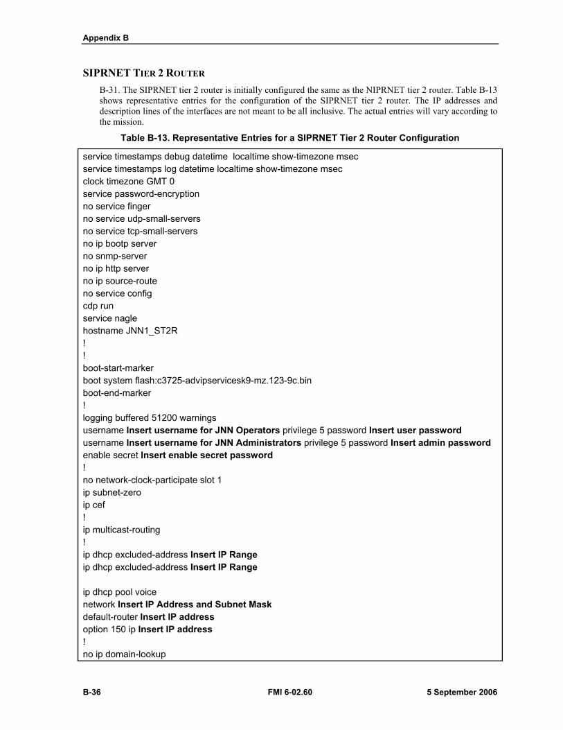
Appendix B
B-36 FMI 6-02.60 5 September 2006
SIPRNET TIER 2 ROUTER B-31. The SIPRNET tier 2 router is initially configured the same as the NIPRNET tier 2 router. Table B-13 shows representative entries for the configuration of the SIPRNET tier 2 router. The IP addresses and description lines of the interfaces are not meant to be all inclusive. The actual entries will vary according to the mission.
Table B-13. Representative Entries for a SIPRNET Tier 2 Router Configuration
service timestamps debug datetime localtime show-timezone msec service timestamps log datetime localtime show-timezone msec clock timezone GMT 0 service password-encryption no service finger no service udp-small-servers no service tcp-small-servers no ip bootp server no snmp-server no ip http server no ip source-route no service config cdp run service nagle hostname JNN1_ST2R ! ! boot-start-marker boot system flash:c3725-advipservicesk9-mz.123-9c.bin boot-end-marker ! logging buffered 51200 warnings username Insert username for JNN Operators privilege 5 password Insert user password username Insert username for JNN Administrators privilege 5 password Insert admin password enable secret Insert enable secret password ! no network-clock-participate slot 1 ip subnet-zero ip cef ! ip multicast-routing ! ip dhcp excluded-address Insert IP Range ip dhcp excluded-address Insert IP Range ip dhcp pool voice network Insert IP Address and Subnet Mask default-router Insert IP address option 150 ip Insert IP address ! no ip domain-lookup

Joint Network Node Components and Connectivity
5 September 2006 FMI 6-02.60 B-37
Table B-13. Representative Entries for a SIPRNET Tier 2 Router Configuration
ip domain-name jnn.army.smil.mil ! ! SSH must be configured. ip ssh time-out 60 ip ssh authentication-retries 2 ! AAA authentication and authorization must be configured for SCP to work. aaa new-model aaa authentication login default local aaa authorization exec default local ! Enables SCP ip scp server enable ! crypto key generate rsa ! ip audit po max-events 100 no ftp-server write-enable ! class-map match-all SIPRdata match not dscp af31 match not dscp ef match input-interface Vlan222 match input-interface Vlan6 ! policy-map SIPRdata class SIPRdata set dscp af21 ! ! ! ! ! ! ! ! ! no crypto isakmp enable ! ! ! ! interface Loopback0 ip address Insert IP address and subnet mask no ip directed-broadcast no ip proxy-arp ! interface Tunnel1 description multi-point Tunnel to Bns
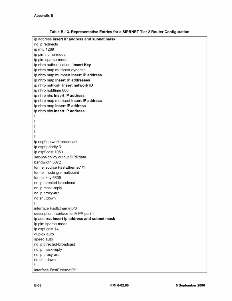
Appendix B
B-38 FMI 6-02.60 5 September 2006
Table B-13. Representative Entries for a SIPRNET Tier 2 Router Configuration
ip address Insert IP address and subnet mask no ip redirects ip mtu 1289 ip pim nbma-mode ip pim sparse-mode ip nhrp authentication Insert Key ip nhrp map multicast dynamic ip nhrp map multicast Insert IP address ip nhrp map Insert IP addresses ip nhrp network Insert network ID ip nhrp holdtime 600 ip nhrp nhs Insert IP address ip nhrp map multicast Insert IP address ip nhrp map Insert IP address ip nhrp nhs Insert IP address ! ! ! ! ! ip ospf network broadcast ip ospf priority 3 ip ospf cost 1050 service-policy output SIPRdata bandwidth 3072 tunnel source FastEthernet1/1 tunnel mode gre multipoint tunnel key 6805 no ip directed-broadcast no ip mask-reply no ip proxy-arp no shutdown ! interface FastEthernet0/0 description Interface to IA PP port 1 ip address Insert Ip address and subnet mask ip pim sparse-mode ip ospf cost 14 duplex auto speed auto no ip directed-broadcast no ip mask-reply no ip proxy-arp no shutdown ! interface FastEthernet0/1

Joint Network Node Components and Connectivity
5 September 2006 FMI 6-02.60 B-39
Table B-13. Representative Entries for a SIPRNET Tier 2 Router Configuration
description Interface to IA PP port 2 ip pim sparse-mode no ip address no shutdown duplex auto speed auto no ip directed-broadcast no ip mask-reply no ip proxy-arp ! interface Serial0/0 description Interface to FEC2/1 through CPP A-A5 ip unnumbered Loopback0 ip pim sparse-mode no shutdown pulse-time 5 ip ospf cost 22 encap ppp no ip directed-broadcast no ip mask-reply no ip proxy-arp ! interface Serial0/1 description Interface to FEC2/2 through CPP A-A6 ip unnumbered Loopback0 ip pim sparse-mode pulse-time 5 ip ospf cost 22 encap ppp no ip directed-broadcast no ip mask-reply no ip proxy-arp no shutdown ! interface Serial0/2 description Interface to KIV-19 #5 through CPP A-A11 ip unnumbered Loopback0 ip pim sparse-mode no shutdown pulse-time 5 ip ospf cost 22 encap ppp no ip directed-broadcast no ip mask-reply no ip proxy-arp !
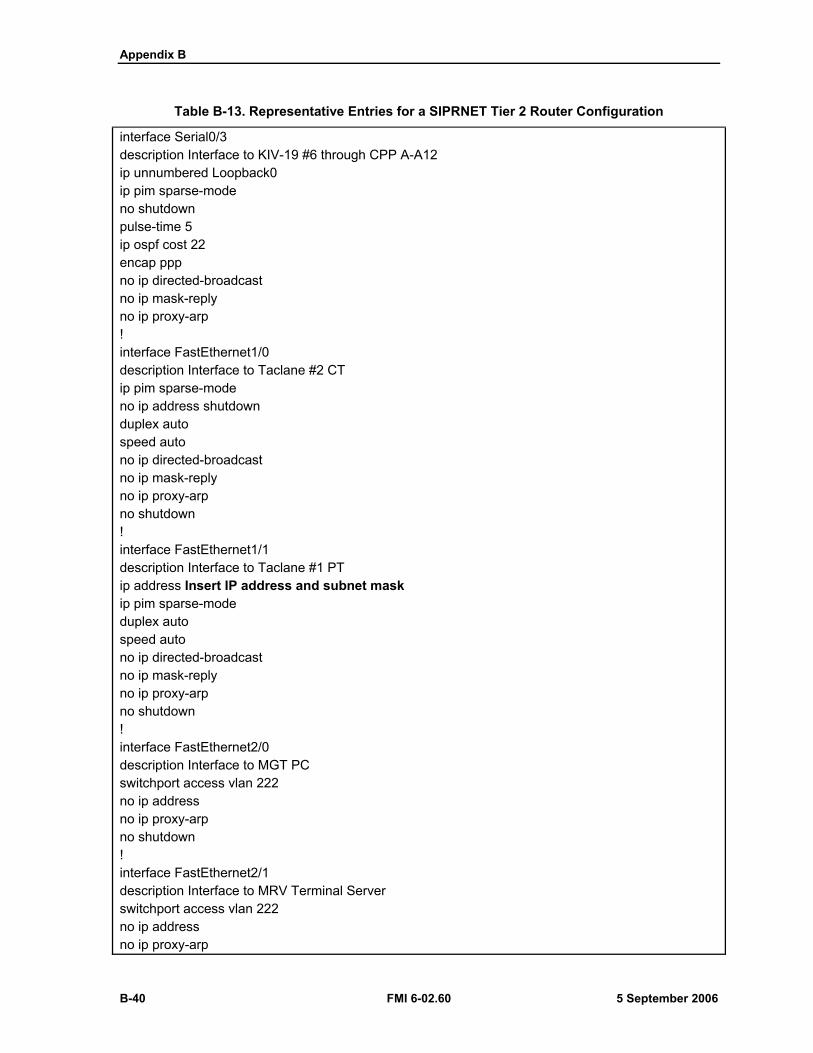
Appendix B
B-40 FMI 6-02.60 5 September 2006
Table B-13. Representative Entries for a SIPRNET Tier 2 Router Configuration
interface Serial0/3 description Interface to KIV-19 #6 through CPP A-A12 ip unnumbered Loopback0 ip pim sparse-mode no shutdown pulse-time 5 ip ospf cost 22 encap ppp no ip directed-broadcast no ip mask-reply no ip proxy-arp ! interface FastEthernet1/0 description Interface to Taclane #2 CT ip pim sparse-mode no ip address shutdown duplex auto speed auto no ip directed-broadcast no ip mask-reply no ip proxy-arp no shutdown ! interface FastEthernet1/1 description Interface to Taclane #1 PT ip address Insert IP address and subnet mask ip pim sparse-mode duplex auto speed auto no ip directed-broadcast no ip mask-reply no ip proxy-arp no shutdown ! interface FastEthernet2/0 description Interface to MGT PC switchport access vlan 222 no ip address no ip proxy-arp no shutdown ! interface FastEthernet2/1 description Interface to MRV Terminal Server switchport access vlan 222 no ip address no ip proxy-arp
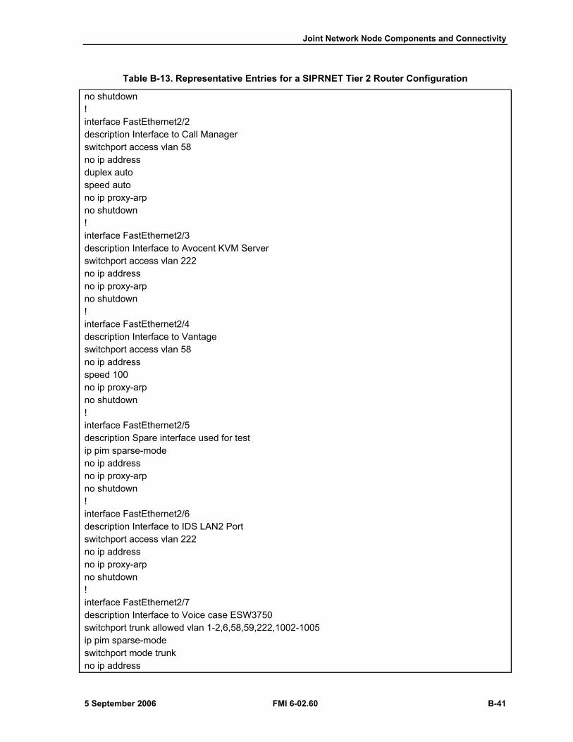
Joint Network Node Components and Connectivity
5 September 2006 FMI 6-02.60 B-41
Table B-13. Representative Entries for a SIPRNET Tier 2 Router Configuration
no shutdown ! interface FastEthernet2/2 description Interface to Call Manager switchport access vlan 58 no ip address duplex auto speed auto no ip proxy-arp no shutdown ! interface FastEthernet2/3 description Interface to Avocent KVM Server switchport access vlan 222 no ip address no ip proxy-arp no shutdown ! interface FastEthernet2/4 description Interface to Vantage switchport access vlan 58 no ip address speed 100 no ip proxy-arp no shutdown ! interface FastEthernet2/5 description Spare interface used for test ip pim sparse-mode no ip address no ip proxy-arp no shutdown ! interface FastEthernet2/6 description Interface to IDS LAN2 Port switchport access vlan 222 no ip address no ip proxy-arp no shutdown ! interface FastEthernet2/7 description Interface to Voice case ESW3750 switchport trunk allowed vlan 1-2,6,58,59,222,1002-1005 ip pim sparse-mode switchport mode trunk no ip address

Appendix B
B-42 FMI 6-02.60 5 September 2006
Table B-13. Representative Entries for a SIPRNET Tier 2 Router Configuration
no ip proxy-arp no shutdown ! interface FastEthernet2/8 description Interface to Data case 3745 RTR switchport trunk allowed vlan 1-2,6,58,59,222,1002-1005 ip pim sparse-mode switchport mode trunk no ip address duplex full speed 100 no ip proxy-arp no shutdown ! interface FastEthernet2/9 description Interface to TOC RTR Vlan 6 switchport trunk allowed vlan 1-2,6,58,59,222,1002-1005 ip pim sparse-mode switchport mode trunk no ip address duplex full speed 100 no ip proxy-arp no shutdown ! interface FastEthernet2/10 description Interface to TOC RTR Vlan 6 switchport trunk allowed vlan 1-2,6,58,59,222,1002-1005 ip pim sparse-mode switchport mode trunk no ip address duplex full speed 100 no ip proxy-arp no shutdown ! interface FastEthernet2/11 no ip address duplex full speed 100 no ip proxy-arp no shutdown ! interface FastEthernet2/12 description Interface to IA PP port 3 no ip address

Joint Network Node Components and Connectivity
5 September 2006 FMI 6-02.60 B-43
Table B-13. Representative Entries for a SIPRNET Tier 2 Router Configuration
ip pim sparse-mode no ip proxy-arp no shutdown ! interface FastEthernet2/13 description Interface to SVoice Gateway Router switchport access vlan 58 no ip address ip pim sparse-mode no ip proxy-arp no shutdown ! interface FastEthernet2/14 no ip address ip pim sparse-mode no ip proxy-arp no shutdown ! interface FastEthernet2/15 description Spare interface used for test no ip address ip pim sparse-mode no ip proxy-arp no shutdown ! interface Vlan1 no ip address ip pim sparse-mode no ip directed-broadcast no ip mask-reply no ip proxy-arp no shutdown ! interface Vlan222 ip address Insert IP address and subnet mask ip pim sparse-mode no ip directed-broadcast no ip mask-reply no ip proxy-arp no shutdown ! interface Vlan58 description Voice Vlan for CM and Phones ip address Insert IP address and subnet mask no ip directed-broadcast no ip mask-reply
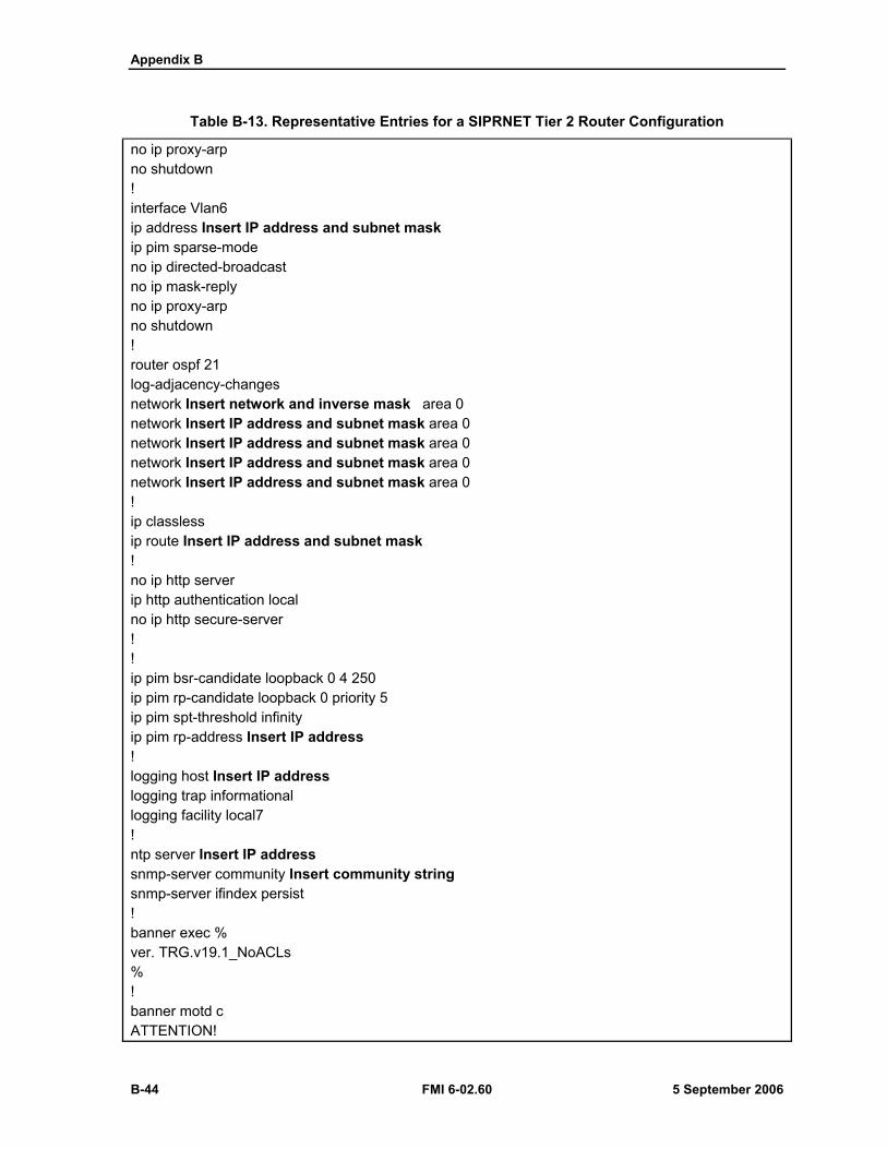
Appendix B
B-44 FMI 6-02.60 5 September 2006
Table B-13. Representative Entries for a SIPRNET Tier 2 Router Configuration
no ip proxy-arp no shutdown ! interface Vlan6 ip address Insert IP address and subnet mask ip pim sparse-mode no ip directed-broadcast no ip mask-reply no ip proxy-arp no shutdown ! router ospf 21 log-adjacency-changes network Insert network and inverse mask area 0 network Insert IP address and subnet mask area 0 network Insert IP address and subnet mask area 0 network Insert IP address and subnet mask area 0 network Insert IP address and subnet mask area 0 ! ip classless ip route Insert IP address and subnet mask ! no ip http server ip http authentication local no ip http secure-server ! ! ip pim bsr-candidate loopback 0 4 250 ip pim rp-candidate loopback 0 priority 5 ip pim spt-threshold infinity ip pim rp-address Insert IP address ! logging host Insert IP address logging trap informational logging facility local7 ! ntp server Insert IP address snmp-server community Insert community string snmp-server ifindex persist ! banner exec % ver. TRG.v19.1_NoACLs % ! banner motd c ATTENTION!

Joint Network Node Components and Connectivity
5 September 2006 FMI 6-02.60 B-45
Table B-13. Representative Entries for a SIPRNET Tier 2 Router Configuration
THIS IS A DOD COMPUTER SYSTEM. BEFORE PROCESSING CLASSIFIED INFORMATION, CHECK THE SECURITY ACCREDITATION LEVEL OF THIS SYSTEM. DO NOT PROCESS, STORE OR TRANSMIT INFORMATION CLASSIFIED ABOVE ACCREDITATION LEVEL OF THIS SYSTEM. THIS COMPUTER SYSTEM, INCLUDING ALL RELATED EQUIPMENT, NETWORKS AND NETWORK DEVICES (INCLUDES INTERNET ACCESS) ARE PROVIDED ONLY FOR AUTHORIZED U.S.GOVERNMENT USE. DOD COMPUTER SYSTEMS MAY BE MONITORED FOR ALL LAWFUL PURPOSES, INCLUDING TO ENSURE THEIR USE IS AGAINST UNAUTHORIZED ACCESS, AND TO VERIFY SECURITY PROCEDURES, SURVIVABILITY, AND OPERATIONAL SECURITY. MONITORING INCLUDES, BUT IS NOT LIMITED TO, ACTIVE ATTACKS BY AUTHORIZED DOD ENTITIES TO TEST OR VERIFY THE SECURITY OF THIS SYSTEM. DURING MONITORING, INFORMATION MAY BE EXAMINED, RECORDED, COPIED, AND USED FOR AUTHORIZED PURPOSES. ALL INFORMATION, INCLUDING PERSONAL INFORMATION, PLACED ON OR SENT OVER THIS SYSTEM MAY BE MONITORED. USE OF THIS DOD COMPUTER SYSTEM, AUTHORIZED OR UNAUTHORIZED, CONSTITUTES CONSENT TO MONITORING. UNAUTHORIZED USE OF THIS DOD COMPUTER SYSTEM MAY SUBJECT YOU TO CRIMINAL PROSECUTION. EVIDENCE OF UNAUTHORIZED USE COLLECTED DURING MONITORING MAY BE USED FOR ADMINISTRATIVE, CRIMINAL OR OTHER ADVERSE ACTION. USE OF THIS SYSTEM CONSTITUTES CONSENT TO MONITORING FOR ALL LAWFUL PURPOSES. c ! ! line con 0 exec-timeout 5 0 login local ! line aux 0 no exec exec-timeout 0 10 transport input none ! line vty 0 4 login local exec-timeout 5 0 transport input telnet ssh ! end
KG-175 TACLANE B-32. The TACLANE is an INE that can encrypt IP traffic for transmission over IP networks. INEs are used to “tunnel” traffic of one security level through networks of another security level. There are two TACLANEs in the JNN shelter. The first TACLANE has its plain text Ethernet interface connected to the NIPRNET interior router. The cipher text port is connected to the SIPRNET interior router. In this configuration, data from the NIPRNET network can be encrypted and tunneled through the SIPRNET data network. If required, the plain and cipher text connections on the TACLANE can be reconfigured by cabling to tunnel SIPRNET through NIPRNET. The second TACLANE in the shelter has its cipher text interface connected to the VPN router, and its plain text interface connected to the SIPRNET interior router. The purpose of this configuration is to allow SIPRNET data to be encrypted as it traverses the Ku TDMA transmission system. Figure B-7 illustrates the Secure Virtual Network with TACLANES, and Table B-14 shows the steps for basic configuration of the KG-175.

Appendix B
B-46 FMI 6-02.60 5 September 2006
Figure B-7. Secure Virtual Network with TACLANEs
Table B-14. Configuring the TACLANE
1 To set date and time go to the OFFLINE MAIN MENU and select MAINT. 2 From Maintenance menu select DATE/TIME. 3 Use arrow keys to navigate to a particular digit of date and time. 4 Use +DIGIT and –DIGIT to increase or decrease each digit. 5 Select DONE when finished and YES to save changes. 6 Select YES to save changes and restart TACLANE. Entering the TACLANE IP Address. NOTE: The TACLANE requires a Cipher Text IP address and a Plain Text IP address as well as a Cipher Text and Plain Text default gateway. 1 From the Off Line Main Menu select CONFIG. 2 From the Configuration menu select NETWORK. 3 From the Configuration menu select IP COMM. 4 From the IP Communications menu select IP ADDRESS. 5 Use arrow keys to navigate to a particular digit of an IP address. Use +DIGIT and –DIGIT
function keys to increase or decrease each digit. Enter IP addresses for TL CT IP, TL PT IP, GWY CT IP, and GWY PT IP.
6 Select DONE when finished. 7 Select YES to save changes, restart TACLANE , and return to Offline Main Menu. Assign a Subnet Mask 1 From Offline menu select CONFIG. 2 From Configuration menu select NETWORK. 3 From Configuration Network menu select IP COMM. 4 From IP Communications menu select SUBNET MASK. 5 Use arrow keys to navigate to a particular digit of subnet mask. Use +DIGIT and –DIGIT

Joint Network Node Components and Connectivity
5 September 2006 FMI 6-02.60 B-47
Table B-14. Configuring the TACLANE
function keys to increase or decrease each digit. Enter CT and PT subnet mask. 6 Select DONE when finished. 7 Select YES to save changes and return to IP Communications menu. Filling FIREFLY Vector Set. NOTE: The TACLANE must be offline with no security level selected. Only one FireFly Vector Set may be filled. Any existing FireFly Vector Set must be deleted. 1 Attach end of fill cable to DTD serial fill port and the other end to TACLANE serial fill port. 2 From Offline Main Menu select KEY MGMT. 3 From Key Management window select FILL. 4 FILL FIREFLY VS menu is displayed. 5 Configure DTD to transmit operations FireFly Vector Set. a Power on DTD. b Highlight APPL and press ENTER. c Navigate down to Fill and press ENTER. d Use arrow key to highlight XMIT and press ENTER. e At Select a Transmit Mode highlight FILL and press ENTER. f Highlight Select and use down arrow to find required FireFly key. Each TACLANE in network
must have a unique FireFly key. Press ENTER. g Use arrow key to highlight Send and press ENTER. h At Send To screen highlight Direct and press ENTER. i At Connect to station press Send. 6 Select READY on TACLANE. 7 Screen displays “Initiate fill device operations or abort.” Transmit operations FireFly Vector
Set. 8 Select DONE and M_MENU to return to main menu. Setting FireFly Security Level 1 From Offline Main Menu select Operations. 2 From Operations menu select SELECT LVL. 3 Select desired security level. Configuring TACLANE static routing. NOTE: The TACLANE must be configured with routing information for any remote TACLANE it will establish call paths with. 1 From Offline Main Menu select CONFIG. 2 From Configurations menu select SECURITY. 3 From Security menu select STATIC RTE. 4 From Static Route Generation menu select CREATE. 5 Enter network ID, subnet mask and TACLANE CT IP address of remote network you are
creating a route for. 6 Select DONE when finished and YES to save changes. Bringing TACLANE online 1 From Offline Main Menu select OPERATION. 2 Select SECURE COMM. 3 The screen should display “SECURE COMM MAIN MENU” and classification level. The
TACLANE is ready for operation.
Appendix B
B-48 FMI 6-02.60 5 September 2006
CDIM B-33. The JNN has three CTM-100C modems in the shelter. The purpose of the CDIMs is to convert the NRZ data into CDI or fiber and to allow interfaces to be extended from the shelter using either CX11230 cable or FO cable. Each CTM-100 modem has two modem functions that convert NRZ data to either CDI or FO data (three CTM-100s yield four modem functions per shelter). Each modem function can be individually programmed for data circuit equipment (DCE) or data terminal equipment (DTE) operation. The typical JNN application is for RS-530 DCE operation. The diphase output can, depending on data rate, drive up to 2 miles. The fiber output, using multimode cable, can drive up to 10 miles at all data rates. Each CTM-100 CDI interface has a corresponding normal through appearance on group patch panel A (modems 1 and 2) and group patch panel C (modem 3). This appearance is connected to a CX11230 SEP connection. The CTM-100 fiber interfaces are directly connected to the TFOCA II SEP connections.
CSUM B-34. There are two CSUMS in the JNN that are stand-alone units. Each of the two modems has four corresponding binding posts on the SEP. The CSUMs have baseband RS-530 DCE interfaces to the GPP. The function of the CSUM is to provide a modem to convert a network interface into a High-data-rate Digital Subscriber Line (HDSL) for transmission over local telephone grade wire connections. The network interfaces are RS-530 data components (TRC ports, NIPRNET serial router ports, KIV-7 encrypted SIPRNET and NIPRNET router serial ports). The modulated output can operate in either one-loop or two-loop mode. In one-loop mode, only one pair of wires is required for connection to the distant end. Data payload in one-loop mode ranges from 128 to 2304 kbs in 64 kbs increments. In two-loop mode, two pairs of wire are required for connection to the distant end. Near end pair one must connect to far end pair one, and near end pair two must be connected to far end pair two. In two-loop mode, payload data rates vary from 256 to 4608 kbs in 128 kbs increments. CSUM binding posts are provided for external wire connection.
VOICE SWITCHING B-35. The JNN voice components are architected to interface with traditional tactical networks and to combine tactical voice with data networks. The main voice components of the JNN voice system are the PBX, Vantage, CM, and VG-248s. The PBX is a COTS voice switch mounted in the shelter. The Vantage acts as an interface between the current forces tactical network and the VoIP network and can be used to supply flood search routing, tactical numbering, and multi-level precedence and preemption for subscribers. The CM software assists in call supervision and gateway call service for VoIP subscribers. Each VG248 converts 48 standard two-wire subscriber interfaces into CM compatible VoIP connections through the data network to the CM. Also included as part of the voice network are the 3750 Ethernet switches (one per security domain). The Ethernet switches are used to terminate and provide power to VoIP subscribers. With the exception of the Ethernet switches and VG248s, all the voice components are mounted internal to the shelter. Figure B-8 shows the NIPRNET voice switching, and Figure B-9 shows the SIPRNET voice switching.
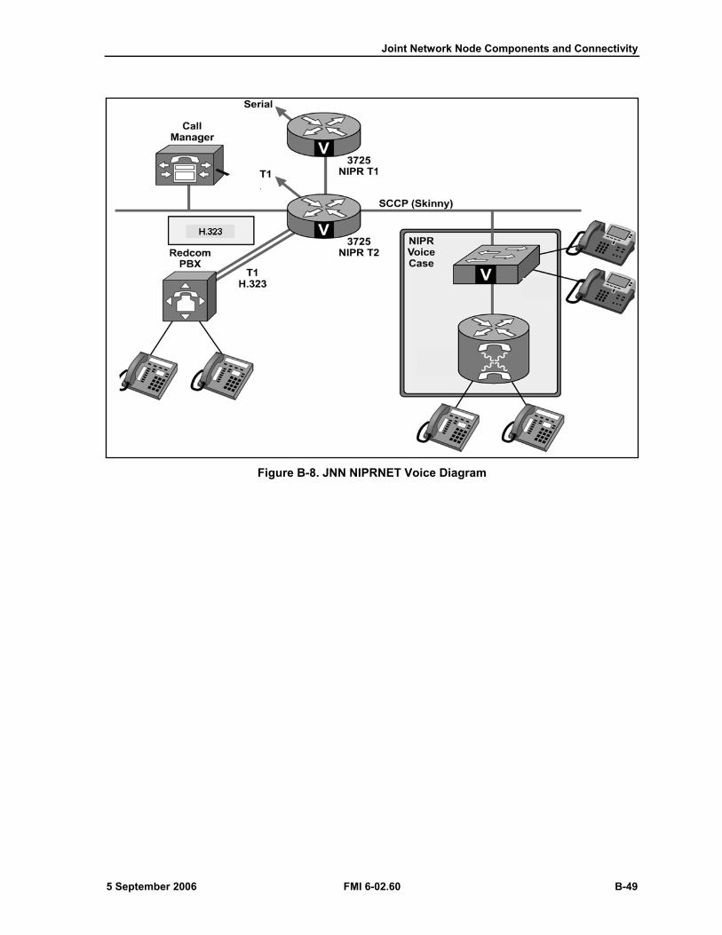
Joint Network Node Components and Connectivity
5 September 2006 FMI 6-02.60 B-49
Figure B-8. JNN NIPRNET Voice Diagram

Appendix B
B-50 FMI 6-02.60 5 September 2006
Figure B-9. JNN SIPRNET Voice Diagram
CM B-36. The CM is a main component in the shelter voice architecture. There are two CMs in the shelter (one dedicated to the NIPRNET domain, and another dedicated to the SIPRNET domain). The CM is physically associated with a particular security domain by KVM and Ethernet connectivity to that domain. The CM software function is hosted on a PC. The CM is a software-based call processing component providing signaling and call control services to integrated telephony applications (e.g., VG-248 subscribers and IP phones). The CM’s primary functions are as follows:
Call processing. Signaling and device control. Dial plan administration. Phone feature administration.
B-37. Table B-15 contains the initial configuration steps for the NIPRNET and SIPRNET CM.
Table B-15. Configuring the Call Manager
NOTE When the Call Manager is installed, the following information is required to be configured: Start Call Manager Server Server Configuration Call Manager Configuration Gatekeeper Trunk Route Groups, Lists, Patterns 1 Install Call Manager software as supplied on the Call Manager Installation Disk.

Joint Network Node Components and Connectivity
5 September 2006 FMI 6-02.60 B-51
Table B-15. Configuring the Call Manager
2 Verify CallManager Services via the CallManager browser interface. a Open Internet Explorer and log in using admin account (jnnadmin, jnn1234$). b Select Application>Cisco CallManager Serviceability. c Select Tools/Service Activation, select jnncm and verify the following services are
enabled. If not. Enable and click update when done. Cisco Call Manager. Cisco TFTP. Cisco Messaging Interface. Cisco IP Voice Media Streaming App. Cisco CTIManager. Cisco MOH Audio Translator. Cisco RIS Data Collector. Cisco Database Layer Monitor. Cisco CDR Insert.
3 Modifying Defaults. a Select Application>Cisco CallManager Serviceability. b Select your server. c Select Cisco CallManager. d Under Cluster Wide Parameter change t302 timer to 5000 msec. 4 Start Call Manager Server. a From the Call Manager Server desktop, double click Internet Explorer. b The Main Call Manager Administrator window opens. 5 Configure Call Manager Server. a From Call Manager Main menu, select System>Server. b Click Add a New Server or Modify the existing server. c Enter IP address of Server. d Click Update. 6 Configure Call Manager. a Choose System>Cisco CallManager. b Click Add a New Cisco Call Manager. c Enter appropriate settings:
Call Manager Name: <IP Address>. Description : Same as the name. Starting Directory Number: trunk prefix plus the start extension range. Ending Directory Number: trunk prefix plus the highest directory number.
d Click Insert to save Cisco CallManager configuration in database. 7 Configure Gatekeeper NOTE: Gatekeeper is only used in SIPRNET domain. a Choose Device>Gatekeeper. The Gatekeeper Configuration page displays. b Select Add a New Gatekeeper or Modify the existing one. Add the following information:
Hostname IP Address: <VantageGK IP>. Description: Registration Time to Live: Registration Retry Timeout:

Appendix B
B-52 FMI 6-02.60 5 September 2006
Table B-15. Configuring the Call Manager
Enabled Device: c Click Insert. The page updates and name of new gatekeeper displays in Gatekeepers list. 8 Configure Intercluster Trunk. a Choose Device>Trunk. b Select Add a New Trunk. Enter the following information using pull down selection.
Trunk Type: Intercluster Trunk (Gatekeeper Controlled). Device Protocol: Intercluster Trunk.
c Click Next. The trunk Configuration screen appears. d Enter the following information:
Device Name: Name of the trunk. Description: A description of the trunk. Calling Party Selection: Originator. Calling Party Presentation: Allowed. (SIPRNET Domain only) Gatekeeper Name: Vantage IP address. Terminal Type: Gatekeeper. Technology Prefix: Trunk prefix number.
e Click Insert. Page updates and name of new trunk displays in trunk list. 9 Configure Route Group. a Select Route Plan>Route Group. b Click Add a New Route Group. c Choose device name ports ALL set order #. d Click Insert. 10 Configure Route List. a Select Route Plan>Route List. b Click Add a New Route List. c Name and description. d Click Insert. 11 Configure Route Pattern. a Select Route Plan>Route Pattern. b Click Add a New Route Pattern. c Enter appropriate Route Pattern. d Click Insert. 12 Restart Call Manager to register with the Gatekeeper. a Select Application>Cisco Call Manager Serviceability. b Select Tools>Control Center. c Click on Server. d Select Cisco Call Manager. e Click Stop. f Click Start.
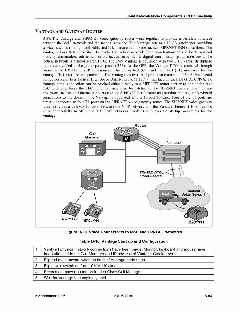
Joint Network Node Components and Connectivity
5 September 2006 FMI 6-02.60 B-53
VANTAGE AND GATEWAY ROUTER B-38. The Vantage and SIPRNET voice gateway router work together to provide a seamless interface between the VoIP network and the tactical network. The Vantage acts as a H.323 gatekeeper providing services such as routing, bandwidth, and link management to non-tactical SIPRNET JNN subscribers. The Vantage allows JNN subscribers to invoke the tactical network flood search algorithms to locate and call properly classmarked subscribers in the tactical network. Its digital transmission group interface to the tactical network is a flood search DTG. The JNN Vantage is equipped with two DTG cards. Its diphase outputs are cabled to the group patch panel (GPP). At the GPP, the Vantage DTGs are normal through connected to CX-11230 SEP appearances. The cipher text (CT) and plain text (PT) interfaces for the Vantage TED interfaces are patchable. The Vantage has two serial ports that connect to CPP-A. Each serial port corresponds to a Tactical High Speed Data Network (THSDN) interface on each DTG. At CPP-A, the Vantage serial connection can be patched either directly to a SIPRNET router port or to one of the four FEC functions. From the FEC unit, they may then be patched to the SIPRNET routers. The Vantage processor card has an Ethernet connection to the SIPRNET tier 2 router and monitor, mouse, and keyboard connections to the domain. The Vantage is populated with a 16-port T1 card. Four of the T1 ports are directly connected to four T1 ports on the SIPRNET voice gateway router. The SIPRNET voice gateway router provides a gateway function between the VoIP network and the Vantage. Figure B-10 shows the voice connectivity to MSE and TRI-TAC networks. Table B-16 shows the startup procedures for the Vantage.
Figure B-10. Voice Connectivity to MSE and TRI-TAC Networks
Table B-16. Vantage Start up and Configuration
1 Verify all physical network connections have been made. Monitor, keyboard and mouse have been attached to the Call Manager and IP address of Vantage Gatekeeper set.
2 Flip red main power switch on back of Vantage node to on. 3 Flip power switch on front of KIV-19’s to on. 4 Press main power button on front of Cisco Call Manager. 5 Wait for Vantage to completely boot.

Appendix B
B-54 FMI 6-02.60 5 September 2006
Table B-16. Vantage Start up and Configuration
6 Log into Vantage operating system from the Vantage Console. Enter user name : administrator. Enter password: password.
7 Double click Internet Explorer icon from desktop. 8 Observe the default homepage is the Vantage gatekeeper. 9 Log in with the appropriate username and password.
Enter User name: gdadmin. Enter password: helicopter.
10 Select Registered Gateways under H.323 Entities header and verify that Cisco router (JNN3725) and Call Manager (cm855_1) are displayed with their respective prefixes.
11 Select Node Configuration under the Node header and verify/configure IAC, Switch Code, Operator Number, and …, fields as desired.
12 Select Affiliation Lists under Subscribers header, scroll down, and click on desired affiliation list number. On Affiliation List Details screen select Affiliate.
13 Select Node Timing under Node header and verify/configure sources for Primary Master and Backup timing.
14 Ensure that necessary COMSEC has been loaded into KIV-19s within Vantage node. 15 Ensure DTG at PBX has been configured and initialized. 16 Select DTG Characteristics under Node header. There are 2 available DTGs that can be (M)
Modified, (D) Deleted, and/or (R) Reset. (M) Modify desired DTG's characteristics selecting associated blue M box. At Modify DTG Characteristics screen, change desired DTG setting(s) and select OK button on top right of screen when finished. It is recommended DTG be (R) Reset after modifications have been made. (D) Delete function will remove DTG assignment from Vantage and is not recommended without consulting Quick Reference Guide. (R) Reset desired DTG by selecting associated green R box. Select OK at acknowledgement prompt. Note: Verify LED indicators on front of respective DTG card fall in sync (switch from red to all green within approx. 30s after (R) Reset).
17 Using the Affiliated Subscribers command, verify that each affiliated subscriber has the following information displayed: TUID. Personal Code. Profile number. Indication if subscriber is a PBX subscriber.
18 Select Node Timing from Menu and set the Primary Master and Backup. 19 Select OK.
PBX B-39. The JNN PBX is a one-shelf COTS ISDN gateway switch (IGX). The T1 interfaces are directly connected to the GPP. From the GPP, the T1s may be patched to the SEP or to TRC primary rate card (PRC) ports. The 32 plain old telephone service (POTS) lines are directly connected to the SEP. The users may be connected to the SEP via two standard 1077 junction boxes. One junction box will allow the connection of 24 two-wire pairs or subscribers. The other will provide two two-wire terminations and direct current (DC) closure commercial office lines (when the PBX is configured with its alternate population of a DC closure card). It should be noted that from the timeslot perspective the IGX shelf is over-subscribed with the 4 T1s and 32 POTS subscribers. It is likely that all 4 T1s will not be allocated. The PBX is

Joint Network Node Components and Connectivity
5 September 2006 FMI 6-02.60 B-55
configured via a console port interface. The PBX console interface is directly cabled to a port on the NIPRNET terminal server. The operating system and feature sets have been installed according to the defined configuration and card set provided with it. PBX translations are stored on the processor’s personal computer memory card international association (PCMCIA) translation card (slot 1). These translations contain the defined dialing plan, and routing for the JNN voice network. During system installation or bootup, the PBX system will automatically load the translations from the PCMCIA translation card. An alternate card is supplied with the JNN for connection to two ground-start/loop-start DC closure commercial office trunks. This trunk card, ground-start loop-start ringdown, is installed in slot 9 and replaces the T1 cards occupying slots 9 and 10.
TRC B-40. The TRC is the means of interconnecting and controlling secured and unsecured digital trunks between JNNs as well as a limited number of channel level telephony and data equipment. Connection between any two like ports in the TRC network is possible if there is at least one path between the respective stations. The connection between data points in the network is referenced as a call. This is independent of whether the data path carries voice or data traffic. If a link in the network is broken, and a path providing sufficient bandwidth is available, the TRC automatically reroutes the data calls. The TRC also provides a demand-assigned bandwidth capability that dynamically allocates only the amount of bandwidth needed to support a call (plus a minimal amount of overhead bandwidth). The TRC is a STEP site compatible multiplexer. Configurable inputs for the TRC are serial interfaces, T1 circuits, and diphase interfaces. The TRC can have three standard aggregate outputs. Additionally, the TRC is configured and populated for T1 circuit voice compression and echo cancellation capabilities. The JNN configuration has one shelf. The shelf is populated with TRC common equipment cards and feature cards. The shelf has 12 slot sets with two integral power supplies. A slot set is defined as a front and back card. (Note that some card types do not require both front and back card slots to be simultaneously populated.) The TRC is configurable via a serial interface to the NIPRNET configuration PC. The TRC is configured with trunk modules, data modules, and voice modules. Typically, with the exception of the PrimeVoice Secure-12 (PVS-12) Module, a module is comprised of a front card and a back card.
PRC B-41. The JNN TRC contains two PRC modules that consist of a PRC front card and a DS-1 rear interface card. Each module has two T1 interfaces to yield a system capacity of four T1s. The fundamental purpose of the T1 module is to allow T1 interfaces to be brought into the TRC fabric for multiplexing. The secondary purpose of one of the four PRC interfaces is for system timing. The TRC can be configured to recover and derive clock from a PRC’s T1 interface. Of the four T1 interfaces, one is cabled to be normal through to a T1 output on the GPS. The timing T1 allows TRC timing to be taken directly from the GPS. This is a core element in the JNN system-timing scheme. All four PRC T1 interfaces are connected to the GPP. At the patch panel they may be connected to T1 interfaces off of the PBX, T1 interfaces from the NIPRNET router, or to external T1s via a SEP patch connection.
PVS-12 Module B-42. The PVS-12 Module consists of a single front card without a rear interface card. Each PVS-12 Module provides 12 channels of voice compression. With two cards supplied in the JNN, a total of 24 voice ports may be compressed at any one time.
High Speed Data (HSD) Module B-43. The JNN configuration has four HSD modules. Three are configured with dual RS-530 back cards, and one has a dual CDI DCE back card. The purpose of the HSD card in the system is to allow serial data to be brought into the TRC fabric. The 530 back cards allow RS-530 formatted data to be interfaced to the TRC. The dual CDI card allows either 530 or conditioned diphase formatted data to be interfaced to the TRC. Each of the four HSD modules has two back card RS-530 DCE ports cabled to the communication patch panel. At the communication patch panel, the 530 ports may be patched to NIPRNET serial data interfaces, KIV-7 encrypted SIPRNET serial interfaces, or modems to introduce data from devices external

Appendix B
B-56 FMI 6-02.60 5 September 2006
to the shelter to the TRC. The dual CDI back card has two additional CDI connections to the GPP. At the GPP, the two HSD CDI ports can be connected to the Vantage DTG (not typical), CTM-100 outputs, or to external interfaces via SEP appearances. It should be noted that though the dual CDI back card has both 530 and CDI interfaces for each of its two ports, only one mode can be invoked for a port at a time.
SA-TRK Module B-44. The TRC has three SA-TRK modules. Each module has one interface. The SA-TRK modules are the main aggregate interfaces for the TRC. Information from other voice, data, and trunk modules can be combined and routed out of the TRC via the SA-TRK modules. Each SA-TRK interface connects to the communications patch panel. In a typical application, the SA-TRK will be patched to the plain text interface of a TED KIV-19. The CT interface of the KIV-19 will be patched to a modem to exit the shelter. Figure B-11depicts a TRC block diagram.
Figure B-11. TRC Block Diagram
TRC Timing B-45. The TRC has the capability to recover timing from one of six external sources. The TRC is configured to recover primary timing from the shelter GPS via a T1 on a PRC. Secondary timing may be derived from any trunk interface (maximum of 2). Timing source configuration is done via software strapping of the node and the interface cards. During TRC database initialization, the TRC prompts for timing configuration information. The data for TRC timing may be entered at that time or later. If not entering timing data during the database initialization process, it will be necessary to use the MODIFY NODE command to enter the primary and alternate timing sources. A typical installation will use the PRC digroup 0 to recover timing from the shelter GPS. A secondary backup timing source may be provided from one of the trunk cards.

Joint Network Node Components and Connectivity
5 September 2006 FMI 6-02.60 B-57
TRC Domain B-46. The TRC operates in a domain of nodes. Each individual network is called a domain. A domain is a TRC network that can comprise from one up to 250 nodes. Domains are connected to each other by gateway nodes. A gateway node is physically connected to its neighbor gateway node (NGW) in the other domain through a gateway link (GWL). A gateway link is a trunk-side connection between two domains that enables calls to originate in one domain and terminate in another domain. Local domain parameters are set to the default values when the node is initialized. These parameters are used to specify and configure domain information for the node.
FLEXMUX B-47. The flexmux is a multi-channel synchronous time-division digital multiplexer combined with a digital signal level 3 (DS3) FOM. In the JNN configuration, it has two multiplexed groups. It multiplexes up to four inputs into a single coaxial cable 44.736 Mbs (megabits per second) which is applied to an internal DS3 FOM card. The flexmux has built in self test diagnostics and must be configured through a command line interface.
KIV-7 ENCRYPTION DEVICE B-48. The JNN contains four KIV-7 data encryption devices to encrypt the red SIPRNET serial data lines from the SIPRNET routers before they appear on the black patch panel. Once encrypted by the KIV-7s (and rendered black), the serial lines from the SIPRNET router may be connected to other black interfaces such as multiplexers and modems via the patch panel. A KIV-7, or compatible unit, is required at the far end to decrypt the SIPRNET serial line and interface it to a red SIPRNET device. Figure B-12 shows typical signal flow using a KIV-7.
Figure B-12. Signal Flow Using KIV-7

Appendix B
B-58 FMI 6-02.60 5 September 2006
TED B-49. The JNN shelter has 12 KIV-19 TEDs to perform digital data encryption and decryption in full duplex synchronous operation. They use identical key generators for transmit and receive. The KIV-19s can operate at data rates between 9600 bps and 13 Mbs. When operated in “traditional crypto mode” the KIV-19A is cryptographically compatible with the following equipment types: KG-81, KG-94, KG-94A, KG-194, KG-194A, KG-95, and KIV-19s, when operated at operationally common data rates. The KIV-19s are used in the JNN system to bulk encrypt aggregate data streams (as from the TRC SA-TRK interfaces), or to encrypt serial data streams from the SIPRNET router as a KIV -7 does. Because some systems use the KIV-7 for this and some a KIV-19 and they are not compatible, the JNN has the ability to use either for wider interface compatibility. Figure B-13 shows a typical application of the KIV-19.
Figure B-13. Typical KIV-19 Application
NETWORK MANAGEMENT B-50. A Panasonic Toughbook laptop computer with related software is used within each security domain to provide a manager platform. The node manager provides monitoring and control capabilities that report on the condition of the network components. It also has the capability to build and save device configurations.
SIGNAL ENTRY PANELS B-51. There are three SEPs on the JNN designated as Metal Plate (MP) 1, MP2 and MP3. MP1, as depicted in Figure B-14, provides the cable connections for the SIPRNET domain as well for the current forces DTGs to the Vantage. MP2, as depicted in Figure B-15, provides the cable connections for the NIPRNET domain as well as the GPS and flexmux. MP3, as depicted in Figure B-16, provides the cable connections for the Ku band and GMF.
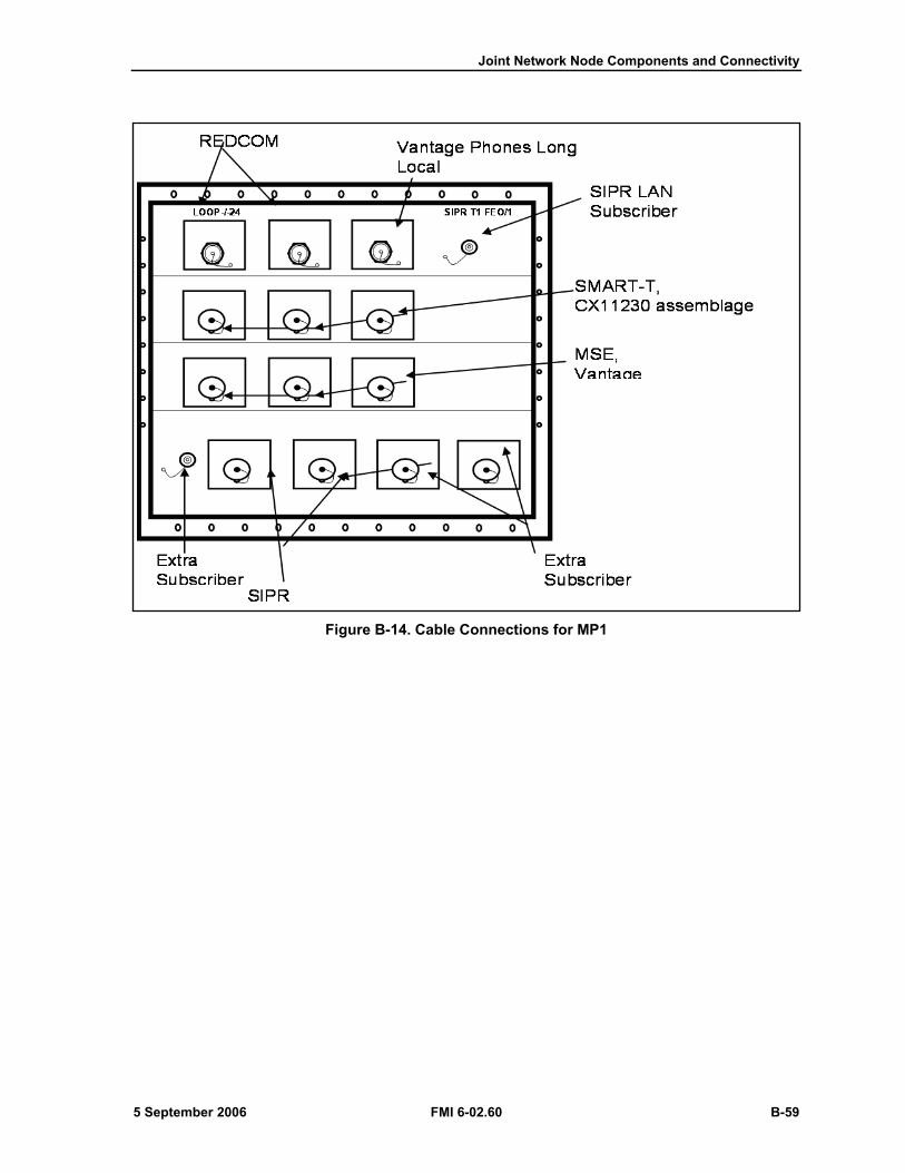
Joint Network Node Components and Connectivity
5 September 2006 FMI 6-02.60 B-59
Figure B-14. Cable Connections for MP1
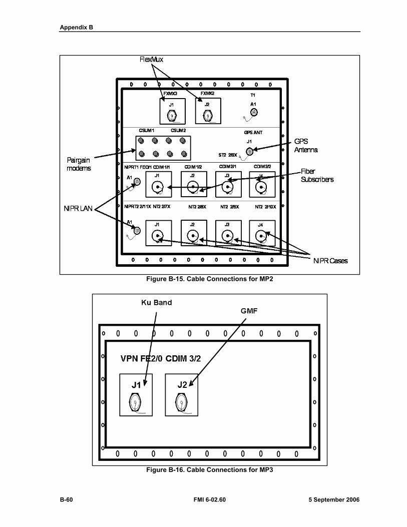
Appendix B
B-60 FMI 6-02.60 5 September 2006
Figure B-15. Cable Connections for MP2
Figure B-16. Cable Connections for MP3

Joint Network Node Components and Connectivity
5 September 2006 FMI 6-02.60 B-61
SATELLITE TRANSPORTABLE TERMINAL B-52. The primary transmission means for the JNN is the satellite transportable terminal. It consists of a 2.4M Ku band antenna mounted on a tactical trailer with associated equipment to provide access to the Ku band commercial satellite constellation. It is also configurable for Ka Band as it becomes available. It supports FDMA and TDMA networks at the division or BCT level. See Appendix D for detailed information on the satellite transportable terminal.
TRANSIT CASES B-53. The JNN also has three SIPRNET data cases and two NIPRNET cases that are typically located in the division and BCT TOCs, which provide subscriber support for voice and data. Refer to Appendix C of this manual for detailed information on this equipment.
MAINTENANCE B-54. The following is guidance for troubleshooting and performing operator-maintainer (MOS 25N) level maintenance on the JNN. The maintenance on the JNN requires an operator-maintainer who is familiar with the functional operation, information, and troubleshooting procedures contained in the maintenance technical manuals for the JNN equipment.
B-55. Located in Technical Manual 11-5805-861-13&P-1, & P-2 (Operator, Unit and Direct Support Maintenance Manual Including Repair Parts and Special Tools List Central Office, Telephone Automatic AN/TTC-59(V1),(V2)) are troubleshooting charts, equipment indicators, displays, and fault isolation procedures to assist the operator-maintainer with troubleshooting, repairing, and replacing equipment within the JNN.
B-56. The troubleshooting procedures are based on fault indicator observations during normal operations. Fault indicators can be generated by both visual alarms and generated user reports. The visual alarms consist of LEDs which may consist of single or multiple indicators signaling minor or major alarms within the equipment.
B-57. The operator-maintainer has several steps that must be exercised before determining equipment failures. The primary troubleshooting objective is to isolate the failure at the lowest level. Flow charts are provided in the technical manuals to assist in troubleshooting, along with alarm summaries which report results of built in tests.
B-58. Once the failure has been identified, the proper procedures to correct the problem will require knowledge of the process. Within the two level maintenance guidelines, the field level maintenance requires the operator to replace COTS equipment from spares located on site. According to Standard Operating Procedures (SOP) the equipment is forwarded to the S-6 on DA Form 2407 or DA Form 5504 and then to the BCT/DIV Customer Field Service Representative (CFSR).

This page intentionally left blank.

5 September 2006 FMI 6-02.60 C-1
Appendix C
Command Post Node Component Listing, Startup, and Maintenance Procedures
This appendix will cover the CPN component listing, startup, and maintenance procedures. The CPN provides enhanced voice and data capabilities along with the ability to interface directly to the Ku band or LOS radio transmission resources down to the support battalions. The CPN interface cases located at the division and BCT level are deployed with the JNN shelter. The SIPRNET and NIPRNET cases, at the division and BCT level, provide data services and voice switching functions, which provide VoIP, transmission system Ku band services (TDMA and FDMA), and user LAN services for the subscriber to mesh into the GIG. The CPN cases located at the BN are deployed separately with the battalions. The CPN SIPRNET cases provide data services and voice functions which provide only TDMA service to the battalion level.
DIVISION AND BRIGADE INTERFACE CASES C-1. The division and brigade CPNs are lightweight deployable transit cases that consist of SIPRNET and NIPRNET communication processing equipment for voice and data functions. Each division is fielded two CPNs, whereas each BCT is fielded only one. Refer to Figure C-1 for SIPRNET and NIPRNET interface components.
SYSTEM COMPONENTS C-2. The division and BCT CPN configuration consists of SIPRNET and NIPRNET cases. The SIPRNET cases are comprised of interface case A, interface case B, and an UPS case. The NIPRNET cases consist of the interface case B and an UPS case. The BVTC/BITS connects to the SIPRNET voice case to interface with the JNN.
INTERFACE CASE A COMPONENTS C-3. Interface case A provides SIPRNET capability only. With this capability, the interface case provides SIPRNET LAN access for users to the JNN. The SIPRNET interface case supports and provides Web Cache, firewall screening to LAN users, and a transmission control protocol/internet protocol (TCP/IP) performance enhancing proxy in order to provide IP capability over satellite links. The LOS case is compatible with telephony case A to support connections for the SIPRNET data users.

Appendix C
C-2 FMI 6-02.60 5 September 2006
Figure C-1. SIPRNET and NIPRNET Domains
Turbo IP
C-4. The COTS Turbo IP equipment is designed to combat problems of TCP transmission over satellite links. The Space Communications Protocol Standard (SCPS) is a standard-based transport protocol (SCPS-TP) performance enhancement for satellite communication networks. The unit restores network efficiency and overcomes the inherent limitations of TCP/IP on impaired links and enables implementation on a node-by-node basis for deployment and end-to-end data transfer. TCP/IP bottlenecks in an impaired environment (high delay, high bit error rate, or both) are minimized and interoperability with the TCP devices is maintained.
Router
C-5. The COTS router optimizes high performance routing, integrated low density switching, security, voice, IP telephony, and content networking in a single integrated modular unit. The unit incorporates network modules (NMs), WAN interface cards (WICs), and Advance Integration Modules (AIMs) for WAN access, voice gateway, security content, and dial applications. The unit also includes a doublewide form factor that provides support for high density service modules (HDSMs) for higher port density and high performance services.
Media Converter Chassis CPSMC0800-100
C-6. The media converter chassis can accommodate up to eight single-slot media converter slide-in modules or four dual-slot media converters, allowing connection to dissimilar media. The unit is equipped with alternating current (AC) or DC power supplies and fans to dissipate heat from the power supplies and media converter modules.

Command Post Node Component Listing, Startup, and Maintenance Procedures
5 September 2006 FMI 6-02.60 C-3
Firewall
C-7. The firewall provides perimeter and or internal network protection for the IP network. The firewall can be used to protect both the user’s LAN and WAN from harmful packets and attacks. The firewall has four 10/100 auto-sensing ports. The unit can handle up to 100 Mbs of firewall traffic and 20 Mbs of 3 Data Encryption Standard (DES) or AES VPN tunnel traffic simultaneously while using up to 500 policies to filter traffic.
RJ-45 Patch Panel and SEP
C-8. The RJ-45 patch panel is used to extend the 34 RJ-45 Ethernet connections from the Ethernet switch. Also extended to this panel is the console port of the Ethernet switch. The SEP has four TFOCA II connectors; two are connected to the two media converter modules, and two are connected to the uplink gigabyte interface converter (GBIC) modules, thus extending two Gigabit Ethernet and two Fast Ethernet ports over the fiber link. The SEP also includes console ports for the router, the WebCache router module, the Turbo IP, and the firewall. The four 25-pin RS-530 connectors are used for the four serial ports from the WIC2 T router modules.
INTERFACE CASE B COMPONENTS C-9. Interface case B provides capabilities for NIPRNET and SIPRNET applications to the end users. Case B provides NIPRNET access to the JNN via fiber for up to 22 users. The Ethernet switch provides terminations for locally connected data users. The media converters are used to convert Ethernet interfaces to a fiber format for Ethernet switch connectivity to either the JNN shelter or to other case types. Case B is also compatible with the JNN voice case, allowing a single point connection for NIPRNET data users and allowing scalability of IP phone support. When the case is used with case A, it allows SIPRNET scalability access for increased user accounts.
Media Converter Chassis CPSMC0200-200
C-10. The dual-slot chassis can accommodate one or two selectable media converter slide-in modules, allowing connection of two dissimilar media. The unit is powered by an external power supply.
Switch
C-11. The COTS switch is equipped with 24, 10/100 Power over Ethernet (PoE) ports and two small form-factor pluggable (SFP) uplink ports. The unit is capable of providing VoIP phones with in-line power as well as standard IP connections to users. The SFP ports are populated with GLC-SX-SM modules providing two 1000Base links over a multi-mode fiber cable and a wavelength of 850nm.
Media Converter CBFTF1013-100
C-12. This unit is a bridging media converter designed to connect a 10/100 Ethernet media using an RJ-45 connector to a 100Base-FX 1300 multi-mode fiber optic cable using two SC100BASE-FX connectors (transmit and a receive).
RJ-45 Patch Panel and Power Entry Panel
C-13. The RJ-45 patch panel is used to extend the 22 RJ-35 connections from the Ethernet switch network module in the router. The Ethernet ports from the firewall and the Turbo IP as well as an additional Fast Ethernet port from the router’s FA0/0 are also extended through the patch panel. The SEP portion of the panel includes four TFOCA II connectors that are connected to the four media converter modules to extend two Gigabit and two Fast Ethernet ports over fiber. The power entry panel (PEP) connects to an external power source and provides power to transit case equipment through a circuit breaker switch as well as surge protection.

Appendix C
C-4 FMI 6-02.60 5 September 2006
UPS CASE C-14. The UPS transit case supplies power to the JNN interface cases and battalion command post transit cases. The UPS is a 1.0 kW, uninterruptible, AC power supply designed to provide continuous, filtered, surge protected, isolated, and regulated AC power to a computer system. It accepts 120 VAC input power and is provided with internal, rechargeable batteries which will power a 1.0 kW load for a minimum of 10 minutes if AC power input is not available. Batteries used in the UPS are a sealed, lead-acid type. The batteries will not vent any gases, are spill-proof, maintenance free, and may be operated in any position. The battery pack module for the UPS is self-contained. The battery pack module is accessible to the operator from the front of the UPS and may be removed and installed without the use of tools. Electrical connection to the UPS is achieved via a docking connector which connects on insertion of the battery pack module into the UPS.
CONNECTING THE DIVISION, BRIGADE, AND BCT INTERFACE CASES C-15. The division, brigade, and BCT interface transit cases connect to the JNN shelter via two separate domains:
The SIPRNET domain. The NIPRNET domain.
C-16. The connection points for both domains are via TFOCA II connector on the signal entry panels (MP1 and MP2). Each of the possible fiber connection points connect to a media converter inside the shelter. The media converter converts the fiber media to a 100BaseT format. The 100BaseT interface then connects to an Ethernet switch port on the tier 2 router. There are four possible connection points on each domain for the BCT connection. Table C-1 and Table C-2 below depict the connection points for each domain. Refer to Figure C-2 for the JNN case setup. Connect the BCT interface cases as follows:
Connect SIPRNET router case (Case A) 100BS circuit to MP1J2. Connect NIPRNET Ethernet switch case (Case B) 100BS circuit to MP2J2.
Table C-1. SIPRNET Connection Points
SEP Position Corresponding Media Converter
Corresponding SIPRNET Router Port
Comment
MP1A4J1 A7A6A1 Tier 2 port 2/7X Preferred Connection Point MP1A4J2 A7A6A2 Tier 2 port 2/8X MP1A4J3 A7A6A3 Tier 2 port2/9X MP1A4J4 A7A6A4 Tier 2 port 2/10X
Table C-2. NIPRNET Connection Points
SEP Position Corresponding Media Converter
Corresponding NIPRNET Router Port
Comment
MP2A4J1 A7A5A1 Tier 2 port 2/7X MP2A4J2 A7A5A2 Tier 2 port 2/8X Preferred Connection Point MP2A4J3 A7A5A3 Tier 2 port 2/9X MP2A4J4 A7A5A4 Tier 2 port 2/10X

Command Post Node Component Listing, Startup, and Maintenance Procedures
5 September 2006 FMI 6-02.60 C-5
Figure C-2. Connection between JNN and Interface Cases
C-17. The JNN signal entry panel provides one T1 circuit connection on panel MP2. There are no default connections to the SEP T1 connector in the JNN; you must patch in one of the shelter’s T1 circuits using the group patch panel A SEP T1 connection.
BVTC/BITS C-18. The BVTC/BITS provides the capability to introduce video teleconferencing into the JNN system. The JNN will provide one interface case which will connect to the JNN by means of an HDSL modem. The BVTC/BITS connects thru the SIPRNET voice case, and then interfaces at the JNN SEP.
C-19. The BVTC/BITS capability is necessary to provide the commander with access to accurate, timely, situational information while coordinating and interacting with different echelons and adjacent units. The BVTC/BITS is more bandwidth efficient than current forces circuit switched video teleconference (VTC) by giving bandwidth back to the users when it is not operational. The BVTC/BITS uses existing communication LAN infrastructure at the TOCs and across the network backbone.
VOICE CASES C-20. There is one set of JNN voice interface cases allocated for each domain. One set is used for RED voice subscribers and the other is used for BLACK voice subscribers. The JNN voice telephony suite provides IP telephone access and power for 30 VoIP phones. The voice telephony case provides IP conversion for 48 POTS subscribers, Ethernet connectivity for the analog gateway and external server, and a single connection point back to the JNN shelter. Refer to Figure C-3 for voice components.

Appendix C
C-6 FMI 6-02.60 5 September 2006
Figure C-3. Red and Black Voice Telephony Case
SIPRNET Media Converters C-21. There are two 100BaseT to 100BaseFL slide-in media converters housed in a CPSMC0200-200 chassis. The media converters provide an RJ-45 to 100BaseT connection and an RX (receive) and TX (transmit) SC100BaseFL connection to a multi-mode fiber optic cable.
Ethernet Switch C-22. There is one Ethernet switch in the transit case that provides inline power to the VoIP phones.
VG-248 C-23. The VG-248 is an analog gateway that is managed and controlled by the CM software. The analog gateway provides ports for 48 analog phones to connect POTS telephones, modems, and fax machines to the CM IP telephony system. It is equipped with digital signal processing that converts analog voice into IP packets for transport through the IP network using coder/decoder (CODEC). Subscribers receive a local phone number and services from the CM server. After registration with the CM server, the POTS phones may then register with the Vantage gatekeeper function to receive its TUID. Subscribers receive local phone numbers and services from the CM server. Each VG-248 allows 48 analog phones to derive service from the VoIP components in the system. Subscriber connection to each VG-248 is accomplished via RJ-11 connectors on the SEP. Initial configuration of the VG-248 may be accomplished by directly connecting a cable from the node manager laptop directly to the connector on the transit case that corresponds to the VG-248 console port. Subsequent configuration may be either via the direct console port connection or from telnet sessions to the device.

Command Post Node Component Listing, Startup, and Maintenance Procedures
5 September 2006 FMI 6-02.60 C-7
PEP C-24. The voice interface case has a separate PEP installed into the case that connects to a government-furnished external power source. The power and surge protection is supplied to the case equipment through a circuit breaker switch. One grounding stud is present for means of a grounding point for the case.
Patch Panel C-25. The patch panel is used to extend the connections from the various types of media that are used within the system. On the patch panel there are extended console ports for the Ethernet switches, analog gateway, and LAN ports. For signal entry, the panel has two TFOCA II connectors that are connected to the media converter which will extend the 2 GB over fiber optic cable.
UPS C-26. The UPS is housed in a deployable transit case. It supplies power for the JNN voice interface equipment transit case. The UPS is a 1.0 kW, uninterruptible, AC power supply designed to provide continuous, filtered, surge protected, isolated, and regulated AC power to a computer system. It accepts 120 VAC input power and is provided with internal, rechargeable batteries which will power a 1.0 kW load for a minimum of 10 minutes if AC power inputs are not available. Batteries used in the UPS are valve regulated, nonspillable, and flame retardant, lead-acid type. The batteries do not vent any gases, are maintenance free, and may be operated in any position. The battery pack module for the UPS is self-contained. The battery pack module is accessible to the operator from the front of the UPS. Electrical connection to the UPS is achieved via a docking connector which mates on insertion of the battery pack module into the UPS.
BATTALION COMMAND POST NODE SYSTEM COMPONENTS C-27. The CPN cases at the battalion level are deployed with the battalions. There will be one CPN located at the BN level to provided extended services. The CPN consists of a router case, a VPN case, an LOS case, and two 1 kW UPS cases. The router case interfaces to the Ku TDMA transmission network through a fiber optic connection to the VPN case. Since the Ku transmission network is a black network, and the VPN case is also black, the Ethernet interface between the VPN and router cases is encrypted by a TACLANE within the router case. The router case contains a firewall for local user protection. Local users connect to the Ethernet switch through an RJ-45 connection block, mounted on the back of the case. The router runs Call Manager Express software to provide a light CM package for local VoIP phone services. The Ethernet switch can provide power to its connections to facilitate the use of VoIP subscribers requiring PoE. To improve performance over satellite systems, a TCP/IP performance enhancement proxy is included in the router case. The router case can support connections of up to 20 subscribers (voice or data). If additional subscriber connectivity is required, then the Ethernet switch from the BCT and division case set may be connected to augment subscriber connection counts. Refer to Figure C-4 for the BN CPN interconnectivity diagram.
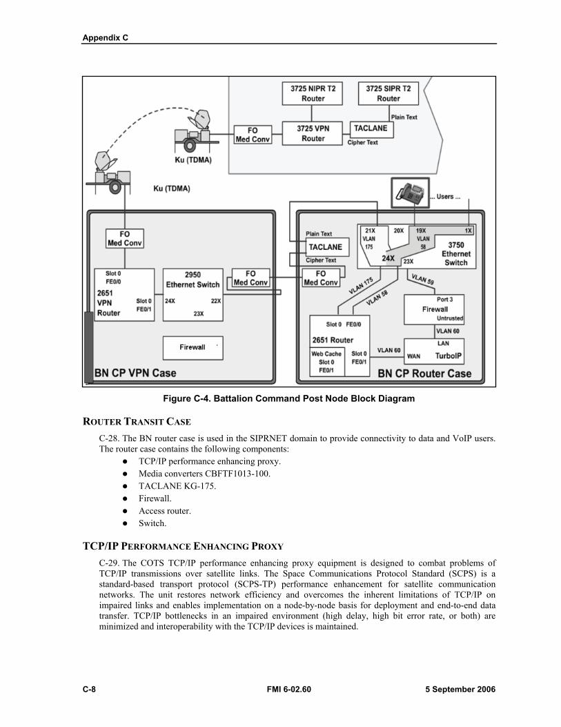
Appendix C
C-8 FMI 6-02.60 5 September 2006
Figure C-4. Battalion Command Post Node Block Diagram
ROUTER TRANSIT CASE C-28. The BN router case is used in the SIPRNET domain to provide connectivity to data and VoIP users. The router case contains the following components:
TCP/IP performance enhancing proxy. Media converters CBFTF1013-100. TACLANE KG-175. Firewall. Access router. Switch.
TCP/IP PERFORMANCE ENHANCING PROXY C-29. The COTS TCP/IP performance enhancing proxy equipment is designed to combat problems of TCP/IP transmissions over satellite links. The Space Communications Protocol Standard (SCPS) is a standard-based transport protocol (SCPS-TP) performance enhancement for satellite communication networks. The unit restores network efficiency and overcomes the inherent limitations of TCP/IP on impaired links and enables implementation on a node-by-node basis for deployment and end-to-end data transfer. TCP/IP bottlenecks in an impaired environment (high delay, high bit error rate, or both) are minimized and interoperability with the TCP/IP devices is maintained.

Command Post Node Component Listing, Startup, and Maintenance Procedures
5 September 2006 FMI 6-02.60 C-9
MEDIA CONVERTER CHASSIS CPSMC0200-200 C-30. The media converter dual-slot chassis can accommodate one or two selectable media converter slide-in modules, allowing connection of two dissimilar media. The unit is powered by an external power supply. This power converter is supplied as part of the media converter chassis and is mounted on the top rack of the case.
MEDIA CONVERTER CBFTF1013-100 C-31. This unit is a bridging media converter designed to connect a 10/100 Ethernet media using an RJ-45 connector to a 100Base-FX 1300nm multi-mode fiber optic cable using two SC100BASE-FX connectors (TX and RX). Two of these modular units populate the CPSMC0200-200 chassis.
KG-175S (TACLANE) INE C-32. The TACLANE unit provides end-to-end encryption of IP packets over a strategic IP network (SIPRNET). This function can be characterized as an encrypted tunnel through another network from one TACLANE to another TACLANE to provide security.
FIREWALL C-33. The firewall provides perimeter and internal network protection for the IP network. This firewall can be used to protect both the LAN and the WAN from harmful packets and attacks. The firewall has five 10/100 auto-sensing ports. It can handle up to 70 Mbs of firewall traffic and 20 Mbs of three DES or AES VPN tunnel traffic simultaneously while using up to 100 policies to filter traffic. It can handle 2000 concurrent sessions, ten site-to-site VPN tunnels, and 100 VPN users.
MULTISERVICE ROUTER C-34. The multiservice router provides a one-network module slot platform with two fixed 10/100BaseT Ethernet port(s), two integrated WIC-2T slots, and one Advanced Integration Module (AIM) slot, with performance up to 40 kbs.
SWITCH C-35. The COTS switch is a 24-port 10/100 PoE switch with two small form-factor pluggable (SFP) uplink ports. The unit is capable of providing VoIP phones with in-line power as well as standard IP connections to users. The SFP ports are populated with GLC-SX-SM providing two 1000Base links over a multi-mode fiber cable and a wavelength of 850nm.
RJ-45 PATCH PANEL AND SEP C-36. The RJ-45 patch panel is used to extend the 21 RJ-45 Ethernet connections from the Ethernet switch. The SEP has four TFOCA II connectors; two are connected to the two media converter modules, and two are connected to the uplink GBIC modules, extending two Gigabit Ethernet and two Fast Ethernet ports over fiber. The SEP also includes console ports for the Ethernet switch, router, WebCache router module, the Turbo IP, and the firewall. The two 25-pin RS-530 connectors are used for the two serial ports from the WIC-2T module. The last connector is for the second media converter module 10/100 side.
VPN TRANSIT CASE EQUIPMENT C-37. The BN VPN case provides the interface to the Ku TDMA transmission system. When used as part of the Quick Shot Network, the case is regarded as black. The VPN case contains the following components:
VPN access router. Firewall.

Appendix C
C-10 FMI 6-02.60 5 September 2006
Media converters CBFTF1013-100. Switch.
C-38. The firewall in the case is included for possible future expansion of the NIPRNET network to the battalion command post and is therefore not presently configured. The VPN router is used to provide a generic router encapsulation (GRE) tunnel encrypted by the AES algorithm through the TDMA network to the other Ku endpoints. The media converters provide the conversion from the case’s internal Ethernet to the external fiber connections going to both the Ku assembly and the BN LOS case.
MEDIA CONVERTER CPSMC0200-200 CHASSIS C-39. The media converter CPSMC0200-200 dual-slot chassis can accommodate one or two selectable media converter slide-in modules, allowing connection of two dissimilar media. The unit is powered by an external power supply. The BN VPN case provides the interface to the Ku TDMA transmission system. When used as part of the Quick Shot Network, the case is regarded as black. The VPN case contains the following components:
Media converters CBFTF1013-100. Switch. Firewall. VPN access router.
MEDIA CONVERTER CBFTF1013-100 C-40. This unit is a bridging media converter designed to connect a 10/100 Ethernet media using an RJ-45 connector to a 100Base-FX 1300nm multi-mode fiber optic cable using two SC100BASE-FX connectors (transmit and receive).
SWITCH C-41. The COTS switch is a 24-port 10/100 Ethernet switch capable of providing standard IP connections to users. The switch offers internetwork operating system (IOS) functionality for basic data, video and voice services as well as Standard Image (SI) software.
FIREWALL C-42. The firewall features one Untrust 10/100BaseT Ethernet port, four Trust 10/100BaseT Ethernet ports and provides 70 Mbs of firewall and 20 Mbs of 3DES VPN performance, protecting the LAN as well as public servers such as mail, web, or FTP. The firewall has the following capabilities:
70 Mbs firewall – 2,000 concurrent sessions. 20 Mbs 3DES VPN – 10 IPSec tunnels. 100 policies. 4 Trust and 1 Untrust 10/100 BaseT.
LOS TRANSIT CASE EQUIPMENT C-43. The LOS case is an interface used to access the LOS transmission system. It is used in conjunction with either the CPN VPN case or the CPN router case. Current LOS transmission systems employ diphase modulation as baseband inputs. The LOS case will connect with a serial interface, as from the VPN or router case, and will apply forward error correction and then encrypt via the KIV-19. The signal is modulated using a CTM-100 diphase modem when connected to the LOS transmission system via CX-11230. The cable from the VPN case to the LOS case is a 25-pin, RS-530 cable connected to the SEPs. The BN CPN LOS case is populated to support 2 LOS links as delivered. Refer to Figure C-5 for the LOS block diagram. The LOS case contains the following components:
Conditioned Diphase Modem.

Command Post Node Component Listing, Startup, and Maintenance Procedures
5 September 2006 FMI 6-02.60 C-11
HSFEC unit. KIV-19 (one or two units).
Figure C-5. LOS Block Diagram
CTM-100 Protocol Converter C-44. The CTM-100 protocol converter is a dual-port multiplexer that converts two independent data streams between NRZ, CDI, and fiber while meeting standard and current forces protocols. The unit can also multiplex two high-speed groups of voice or data. This multi-port multiplexer (MUX) is compatible with military switching equipment such as THSDN, MSE, and echelon above corps (EAC) Common Baseline Circuit Switches (CBCS). The output of the MUX is a TRI-TAC framed compatible aggregate. The CTM-100C supports cable drive distances up to 16 km at data rates up to 18.720 Mbs utilizing tactical fiber cable CX-13295, as well as distances up to 3.2 km at data rates up to 4.608 Mbs via copper cables such as CX-11230. The unit’s optical transceivers can drive circuits up to 16 km over single or multi-mode cable.
KIV-19A Rackmount C-45. The KIV-19A rackmount that houses two KIV-19A units and an AC/DC power supply in three separate compartments is installed and secured to a mounting kit in the LOS case. The KIV-19As and the power supply are removable from the front of the rackmount.

Appendix C
C-12 FMI 6-02.60 5 September 2006
KIV-19A TED C-46. The KIV-19A is a trunk encryption device capable of performing digital data encryption and decryption utilizing identical key generators for transmission and reception. It will provide cryptographic security for all classifications of digital data traffic at rates from 9.6 Kbs to 13 Mbs.
PEP C-47. The PEP is a rackmounted power strip that includes a power cord to connect to the UPS power source, a circuit breaker to turn power on or off, and two utility outlets.
SEP C-48. The SEP includes two CX11230 high power assemblies (HVAs) to connect the LOS to the protocol converter in the LOS transit case.
UPS Transit Case C-49. The UPS transit case houses an Uninterruptible Power Supply which supplies power for the JNN interface and BN CPN transit cases.
UPS C-50. The UPS is a 1.0 kW, uninterruptible, AC power supply designed to provide continuous, filtered, surge protected, isolated, and regulated AC power to a computer system. It accepts 120 VAC input power and is provided with internal, rechargeable batteries which will power a 1.0 kW load for a minimum of 10 minutes if AC power input is not available. Batteries used in the UPS are a sealed, lead-acid type. The batteries will not vent any gasses, are spill-proof, maintenance free, and may be operated in any position. The battery pack module for the UPS is self-contained. After the front UPS bezel has been removed, the battery pack module is accessible to the operator from the front, and may be removed and installed. Electrical connection to the UPS is achieved via a docking connector which mates on insertion of the battery pack module into the UPS.
KIV-19A Power Supply C-51. The KIV-19A power supply is installed in the middle compartment of the KIV-19A rackmount. The unit is a redundant power supply capable of operating on AC or DC external power. External power is applied through the rear panel of the KIV-19A rackmount.
HSFEC Unit C-52. The HSFEC provides forward error correction over line of sight radio and satellite links to compensate for inherent signal loss that is experienced in a tactical environment.
CONNECTING THE BN CPN LOS CASE C-53. The battalion uses the LOS case to connect to the JNN via Ku band satellite and also to communicate with other BNs. The battalions communicate to each other with their LOS case, in which the case will be connected to a TRC-190 (V1) via CX11230 cable providing SIPR voice and data services.
CONNECTING THE CPN C-54. The CPN equipment in each case is pre-mounted and the internal signal and power cables are installed in the transit case.
C-55. When applying AC power to the transit cases, the power received is from an associated 1kW UPS. The UPS provides conditioned AC power as well as battery backup protection to the transit cases.
C-56. Apply power to the transit case as follows:

Command Post Node Component Listing, Startup, and Maintenance Procedures
5 September 2006 FMI 6-02.60 C-13
Ensure that a 120 volts, alternating current (VAC) government-furnished equipment (GFE) power source is connected to the transit case UPS and power up the GFE power source. The AC INPUT LED on the front panel of associated UPS should illuminate green.
At the UPS front panel, press the ON button. Wait a few seconds and the battery level indicator should cycle through the battery test. The UPS ON green indicator should illuminate and at least one battery level indicator should illuminate green.
At associated transit case, set PEP circuit breaker (CB) 1 to ON. Apply power to all other equipment connected to UPS outlets. The transit case units are now powered on.
Figure C-6. Network Diagram of CPN Transit Cases and JNN
CAUTION All units within the transit cases are powered through their respective PEPs. Some units have individual power switches that are not readily accessible from the rear of the transit cases. These switches should remain on at all times and powered off from the PEP circuit breaker CB1. 120 VAC power source is required. Connection to a power source greater than 120 VAC will result in damage or loss of the UPS.
C-57. The signal cables are connected through the SEP. The following table (Table C-3) provides the location through the connection for each connector on the router case.
The first step is to identify the location where to set up the operations. Ensure setup is at least up to 300M away.

Appendix C
C-14 FMI 6-02.60 5 September 2006
If set up is for long durations, the transit cases cannot be stacked more than three high. The preferred method of stacking is the heaviest box on the bottom (SIPRNET) with the lightest on the top (UPS).
Once the boxes are in place, ground the equipment and run the TFOCA II cable out to the trailer. The TFOCA II cable connects to the Ku port on the NIPRNET box, and to the TFOCA II connecter beneath the main circuit panel outside of the generator on the trailer. The cable should be run so that it will not be stepped on or driven over.
Should it be necessary to acquire power from the trailer, be certain that there is enough extension cord to reach the boxes, that it is weather proof, and will not be damaged by vehicle or foot traffic.
Connect the UPS to the power source and let the battery charge without turning the UPS on. Connect the TFOCA II cable to the NIPRNET box and the NIPRNET and SIPRNET power
cables to the UPS box. Connect the CAT5 cable from port 21 slot on the back of the SIPRNET box to the TACLANE
PT slot. Connect an additional CAT5 cable from the TACLANE CT to the NIPRNET 22 slot.
Table C-3. CPN Router Case Connection Points
LOCATION
CONNECTOR DESCRIPTION
CONNECTION FUNCTION
Patch Panel RJ-45 1X Subscriber 1 Patch Panel RJ-45 2X Subscriber 2 Patch Panel RJ-45 3X Subscriber 3 Patch Panel RJ-45 4X Subscriber 4 Patch Panel RJ-45 5X Subscriber 5 Patch Panel RJ-45 6X Subscriber 6 Patch Panel RJ-45 7X Subscriber 7 Patch Panel RJ-45 8X Subscriber 8 Patch Panel RJ-45 9X Subscriber 9 Patch Panel RJ-45 10X Subscriber 10 Patch Panel RJ-45 11X Subscriber 11 Patch Panel RJ-45 12X Subscriber 12 Patch Panel RJ-45 13X Subscriber 13 Patch Panel RJ-45 14X Subscriber 14 Patch Panel RJ-45 15X Subscriber 15 Patch Panel RJ-45 16X Subscriber 16 Patch Panel RJ-45 17X Subscriber 17 Patch Panel RJ-45 18X Subscriber 18 Patch Panel RJ-45 19X Subscriber 19 Patch Panel RJ-45 20X Subscriber 20 Patch Panel RJ-45 21X Subscriber 21 Patch Panel RJ-45 MC2TX TACLANE Patch Panel RJ-45 WEB 2651 XM Router Web Cache SEP RJ-45 2651 Console 2651 Router Console SEP RJ-45 PEP Console Turbo IP Console SEP RJ-45 FireWall Console FireWall Console
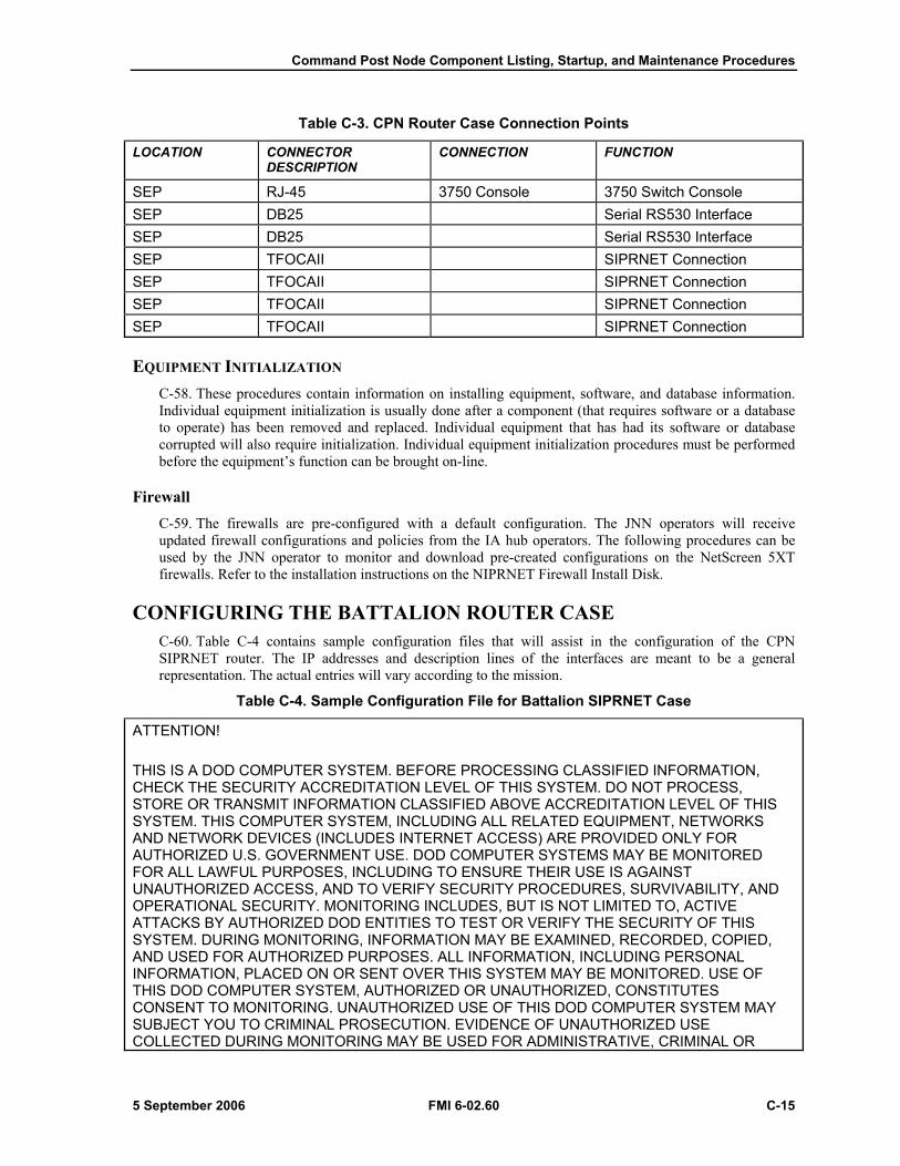
Command Post Node Component Listing, Startup, and Maintenance Procedures
5 September 2006 FMI 6-02.60 C-15
Table C-3. CPN Router Case Connection Points
LOCATION
CONNECTOR DESCRIPTION
CONNECTION FUNCTION
SEP RJ-45 3750 Console 3750 Switch Console SEP DB25 Serial RS530 Interface SEP DB25 Serial RS530 Interface SEP TFOCAII SIPRNET Connection SEP TFOCAII SIPRNET Connection SEP TFOCAII SIPRNET Connection SEP TFOCAII SIPRNET Connection
EQUIPMENT INITIALIZATION C-58. These procedures contain information on installing equipment, software, and database information. Individual equipment initialization is usually done after a component (that requires software or a database to operate) has been removed and replaced. Individual equipment that has had its software or database corrupted will also require initialization. Individual equipment initialization procedures must be performed before the equipment’s function can be brought on-line.
Firewall C-59. The firewalls are pre-configured with a default configuration. The JNN operators will receive updated firewall configurations and policies from the IA hub operators. The following procedures can be used by the JNN operator to monitor and download pre-created configurations on the NetScreen 5XT firewalls. Refer to the installation instructions on the NIPRNET Firewall Install Disk.
CONFIGURING THE BATTALION ROUTER CASE C-60. Table C-4 contains sample configuration files that will assist in the configuration of the CPN SIPRNET router. The IP addresses and description lines of the interfaces are meant to be a general representation. The actual entries will vary according to the mission.
Table C-4. Sample Configuration File for Battalion SIPRNET Case
ATTENTION! THIS IS A DOD COMPUTER SYSTEM. BEFORE PROCESSING CLASSIFIED INFORMATION, CHECK THE SECURITY ACCREDITATION LEVEL OF THIS SYSTEM. DO NOT PROCESS, STORE OR TRANSMIT INFORMATION CLASSIFIED ABOVE ACCREDITATION LEVEL OF THIS SYSTEM. THIS COMPUTER SYSTEM, INCLUDING ALL RELATED EQUIPMENT, NETWORKS AND NETWORK DEVICES (INCLUDES INTERNET ACCESS) ARE PROVIDED ONLY FOR AUTHORIZED U.S. GOVERNMENT USE. DOD COMPUTER SYSTEMS MAY BE MONITORED FOR ALL LAWFUL PURPOSES, INCLUDING TO ENSURE THEIR USE IS AGAINST UNAUTHORIZED ACCESS, AND TO VERIFY SECURITY PROCEDURES, SURVIVABILITY, AND OPERATIONAL SECURITY. MONITORING INCLUDES, BUT IS NOT LIMITED TO, ACTIVE ATTACKS BY AUTHORIZED DOD ENTITIES TO TEST OR VERIFY THE SECURITY OF THIS SYSTEM. DURING MONITORING, INFORMATION MAY BE EXAMINED, RECORDED, COPIED, AND USED FOR AUTHORIZED PURPOSES. ALL INFORMATION, INCLUDING PERSONAL INFORMATION, PLACED ON OR SENT OVER THIS SYSTEM MAY BE MONITORED. USE OF THIS DOD COMPUTER SYSTEM, AUTHORIZED OR UNAUTHORIZED, CONSTITUTES CONSENT TO MONITORING. UNAUTHORIZED USE OF THIS DOD COMPUTER SYSTEM MAY SUBJECT YOU TO CRIMINAL PROSECUTION. EVIDENCE OF UNAUTHORIZED USE COLLECTED DURING MONITORING MAY BE USED FOR ADMINISTRATIVE, CRIMINAL OR
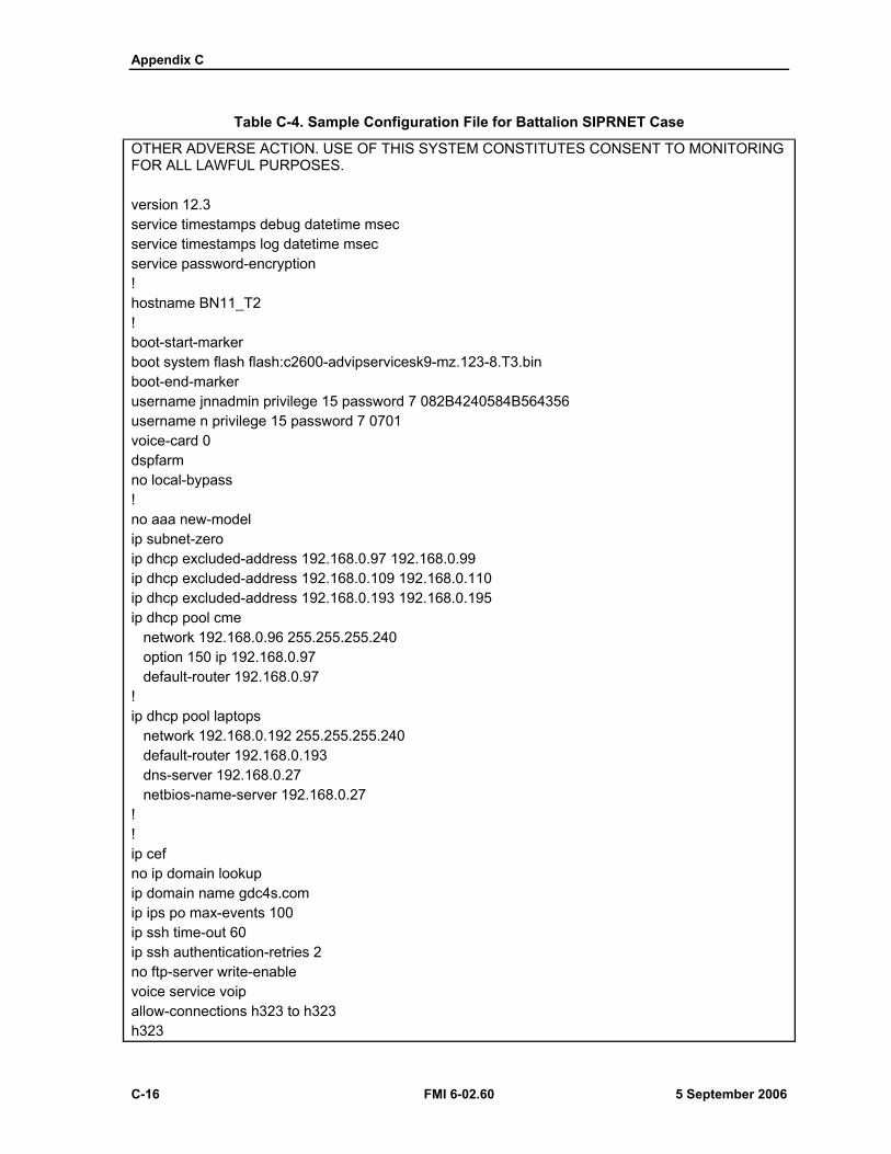
Appendix C
C-16 FMI 6-02.60 5 September 2006
Table C-4. Sample Configuration File for Battalion SIPRNET Case
OTHER ADVERSE ACTION. USE OF THIS SYSTEM CONSTITUTES CONSENT TO MONITORING FOR ALL LAWFUL PURPOSES. version 12.3 service timestamps debug datetime msec service timestamps log datetime msec service password-encryption ! hostname BN11_T2 ! boot-start-marker boot system flash flash:c2600-advipservicesk9-mz.123-8.T3.bin boot-end-marker username jnnadmin privilege 15 password 7 082B4240584B564356 username n privilege 15 password 7 0701 voice-card 0 dspfarm no local-bypass ! no aaa new-model ip subnet-zero ip dhcp excluded-address 192.168.0.97 192.168.0.99 ip dhcp excluded-address 192.168.0.109 192.168.0.110 ip dhcp excluded-address 192.168.0.193 192.168.0.195 ip dhcp pool cme network 192.168.0.96 255.255.255.240 option 150 ip 192.168.0.97 default-router 192.168.0.97 ! ip dhcp pool laptops network 192.168.0.192 255.255.255.240 default-router 192.168.0.193 dns-server 192.168.0.27 netbios-name-server 192.168.0.27 ! ! ip cef no ip domain lookup ip domain name gdc4s.com ip ips po max-events 100 ip ssh time-out 60 ip ssh authentication-retries 2 no ftp-server write-enable voice service voip allow-connections h323 to h323 h323

Command Post Node Component Listing, Startup, and Maintenance Procedures
5 September 2006 FMI 6-02.60 C-17
Table C-4. Sample Configuration File for Battalion SIPRNET Case
call start slow interface Tunnel21 description multipoint Tunnel to JNN ip address 10.10.10.1 255.255.255.0 no ip redirects ip mtu 1416 ip pim nbma-mode ip pim sparse-mode ip nhrp authentication sipr ip nhrp map 10.10.10.9 172.16.0.188 ip nhrp map multicast 172.16.0.188 ip nhrp map 10.10.10.29 172.16.199.212 ip nhrp map multicast 172.16.199.212 ip nhrp network-id 99 ip nhrp holdtime 300 ip nhrp nhs 10.10.10.9 ip nhrp nhs 10.10.10.29 ip ospf network point-to-multipoint ip ospf priority 0 tunnel source FastEthernet0/0.2 tunnel mode gre multipoint tunnel key 100000 interface Loopback0 ip address 14.1.2.1 255.255.255.255 ! interface FastEthernet0/0 description Local LAN no ip address speed auto full-duplex interface FastEthernet0/0.1 encapsulation dot1Q 1 native ! interface FastEthernet0/0.2 encapsulation dot1Q 175 ip address 172.16.0.124 255.255.255.248 ! interface FastEthernet0/0.58 encapsulation dot1Q 58 ip address 192.168.0.97 255.255.255.240 h323-gateway voip bind srcaddr 192.168.0.97 interface Serial0/0 no ip address shutdown no fair-queue !

Appendix C
C-18 FMI 6-02.60 5 September 2006
Table C-4. Sample Configuration File for Battalion SIPRNET Case
interface FastEthernet0/1 description Interface to Turbo IP ip address 192.168.0.121 255.255.255.248 speed 10 full-duplex interface Content-Engine1/0 no ip address ip wccp web-cache redirect in service-module external ip address 192.168.0.194 255.255.255.240 service-module ip default-gateway 192.168.0.193 hold-queue 60 out router ospf 21 log-adjacency-changes redistribute connected subnets redistribute static subnets network 10.10.10.0 0.0.0.255 area 0 network 14.1.2.1 0.0.0.0 area 0 network 192.168.0.120 0.0.0.7 area 0 ip classless ip route 172.16.0.112 255.255.255.248 172.16.0.123 ip route 172.16.0.184 255.255.255.248 172.16.0.123 ip route 172.16.199.208 255.255.255.248 172.16.0.123 ip route 192.168.0.192 255.255.255.240 192.168.0.123 ip http server no ip http secure-server ip http path flash: ! ! snmp-server community jnnpublic RO snmp-server community jnnprivate RW snmp-server enable traps tty ! ! tftp-server flash:P00303020214.bin tftp-server flash:P00403020214.bin ! control-plane dial-peer voice 58 voip description Primary route to MSE preference 1 max-conn 1 destination-pattern 58..... session target ipv4:192.168.0.33 codec g711ulaw ip qos dscp cs5 signaling dial-peer voice 9999 voip

Command Post Node Component Listing, Startup, and Maintenance Procedures
5 September 2006 FMI 6-02.60 C-19
Table C-4. Sample Configuration File for Battalion SIPRNET Case
description All other calls go to hub for routing preference 2 max-conn 1 destination-pattern .T session target ipv4:192.168.199.33 codec g711ulaw dial-peer voice 670 voip description Non JNN1 BGE calls to JNN users go to Hub preference 2 max-conn 1 destination-pattern 670.... session target ipv4:192.168.199.33 codec g711ulaw gateway ! ! ! telephony-service load 7910 P00403020214 load 7960-7940 P00303020214 max-ephones 8 max-dn 48 ip source-address 192.168.0.97 port 2000 create cnf-files version-stamp 7960 Jun 14 2004 15:03:42 max-conferences 4 moh music-on-hold.au web admin system name administrator password password ephone-dn 1 number 6701101 ! ! ephone-dn 2 number 6701102 ! ! ephone-dn 3 number 6701103 ! ! ephone-dn 4 ephone 1 mac-address 0011.20F6.85B5 type 7940 button 1:3 ! !

Appendix C
C-20 FMI 6-02.60 5 September 2006
Table C-4. Sample Configuration File for Battalion SIPRNET Case
! ephone 2 mac-address 0011.2111.1644 type 7940 button 1:2 line con 0 exec-timeout 0 0 logging synchronous login local line 33 no activation-character no exec transport preferred none transport input all transport output all line aux 0 line vty 0 4 login local transport input telnet ssh ! ! End
CONFIGURING THE VIRTUAL PRIVATE NETWORK ROUTER C-61. The following table contains sample configuration files that will assist in the configuration of the CPN NIPRNET router. The IP addresses and description lines of the interfaces are meant to be a general representation. The actual entries will vary according to the mission.
Table C-5. Sample Configuration File for Battalion NIPRNET Case
ATTENTION! THIS IS A DOD COMPUTER SYSTEM. BEFORE PROCESSING CLASSIFIED INFORMATION, CHECK THE SECURITY ACCREDITATION LEVEL OF THIS SYSTEM. DO NOT PROCESS, STORE OR TRANSMIT INFORMATION CLASSIFIED ABOVE ACCREDITATION LEVEL OF THIS SYSTEM. THIS COMPUTER SYSTEM, INCLUDING ALL RELATED EQUIPMENT, NETWORKS AND NETWORK DEVICES (INCLUDES INTERNET ACCESS) ARE PROVIDED ONLY FOR AUTHORIZED U.S. GOVERNMENT USE. DOD COMPUTER SYSTEMS MAY BE MONITORED FOR ALL LAWFUL PURPOSES, INCLUDING TO ENSURE THEIR USE IS AGAINST UNAUTHORIZED ACCESS, AND TO VERIFY SECURITY PROCEDURES, SURVIVABILITY, AND OPERATIONAL SECURITY. MONITORING INCLUDES, BUT IS NOT LIMITED TO, ACTIVE ATTACKS BY AUTHORIZED DOD ENTITIES TO TEST OR VERIFY THE SECURITY OF THIS SYSTEM. DURING MONITORING, INFORMATION MAY BE EXAMINED, RECORDED, COPIED, AND USED FOR AUTHORIZED PURPOSES. ALL INFORMATION, INCLUDING PERSONAL INFORMATION, PLACED ON OR SENT OVER THIS SYSTEM MAY BE MONITORED. USE OF THIS DOD COMPUTER SYSTEM, AUTHORIZED OR UNAUTHORIZED, CONSTITUTES CONSENT TO MONITORING. UNAUTHORIZED USE OF THIS DOD COMPUTER SYSTEM MAY SUBJECT YOU TO CRIMINAL PROSECUTION. EVIDENCE OF UNAUTHORIZED USE COLLECTED DURING MONITORING MAY BE USED FOR ADMINISTRATIVE, CRIMINAL OR

Command Post Node Component Listing, Startup, and Maintenance Procedures
5 September 2006 FMI 6-02.60 C-21
Table C-5. Sample Configuration File for Battalion NIPRNET Case
OTHER ADVERSE ACTION. USE OF THIS SYSTEM CONSTITUTES CONSENT TO MONITORING FOR ALL LAWFUL PURPOSES. ! Last configuration change at 15:46:07 UTC Fri Jun 18 2004 ! NVRAM config last updated at 15:56:50 UTC Fri Jun 18 2004 ! version 12.3 service timestamps debug datetime msec service timestamps log datetime msec no service password-encryption ! hostname BTN1_VPN boot-start-marker boot-end-marker ! enable secret 5 $1$D.px$gd22yn0z3DduGIThkXgq5/ enable password Password ! no aaa new-model ip subnet-zero no ip domain lookup ip domain name cisco.com ip audit notify log ip audit po max-events 100 no ftp-server write-enable crypto ca trustpoint cisco1 enrollment retry count 5 enrollment retry period 3 enrollment url http://172.16.0.69:80 revocation-check none ! ! crypto ca certificate chain cisco1 certificate 03 nvram:cisco1ciscoc#5303.cer certificate ca 01 nvram:cisco1ciscoc#5301CA.cer crypto isakmp policy 10 encr aes crypto isakmp key cisco123 address 0.0.0.0 0.0.0.0 ! ! crypto ipsec transform-set aes_set esp-aes esp-sha-hmac ! crypto ipsec profile btn1 set transform-set aes_set interface Tunnel2 ip address 10.0.0.2 255.255.0.0

Appendix C
C-22 FMI 6-02.60 5 September 2006
Table C-5. Sample Configuration File for Battalion NIPRNET Case
ip mtu 1416 ip nhrp authentication dont_say ip nhrp map 10.0.0.1 172.16.0.81 ip nhrp map multicast 172.16.0.81 ip nhrp network-id 99 ip nhrp nhs 10.0.0.1 ip ospf network broadcast tunnel source FastEthernet0/0 tunnel destination 172.16.0.81 tunnel key 100000 tunnel protection ipsec profile btn1 interface FastEthernet0/0 ip address 172.16.0.82 255.255.255.240 duplex auto speed auto no cdp enable no mop enabled ! interface FastEthernet0/1 no ip address shutdown duplex auto speed auto no cdp enable router ospf 21 log-adjacency-changes network 10.0.0.0 0.0.255.255 area 0 network 172.16.0.80 0.0.0.15 area 0 ! ip classless ! ip http server no ip http secure-server ! ! dialer-list 1 protocol ip permit ! ! ! ! control-plane line con 0 exec-timeout 0 0 line 33 no activation-character no exec

Command Post Node Component Listing, Startup, and Maintenance Procedures
5 September 2006 FMI 6-02.60 C-23
Table C-5. Sample Configuration File for Battalion NIPRNET Case
transport preferred none transport input all transport output all line aux 0 line vty 0 4 password jnn1234$ login ! ntp clock-period 17179888 ntp server 172.16.0.27 ! End
COMMAND POST NODE TRANSIT CASE MAINTENENANCE C-62. The following provides guidance for troubleshooting and performing operator-maintainer, Information Systems Specialist (25B), level corrective maintenance on the CPN transit cases. The maintenance on the CPN requires an operator-maintainer who must be familiar with the functional operation, information, and troubleshooting procedures contained in the maintenance technical manuals for the equipment.
C-63. Located in Technical Manuals 11-5895-1791-13&P, 11-5895-1804-13&P (Operator, Unit and Direct Support Maintenance Manual Including Repair Parts and Special Tools List - Switching Group, Digital Data OM-86/T, OM-97/T) are troubleshooting charts, equipment indicators, displays, and fault isolation procedures to assist the operator-maintainer with troubleshooting, repairing, and replacing equipment within the CPN.
C-64. Troubleshooting procedures are based on fault indicator observations during normal operations. Fault indicators can be generated by both visual indicators and generated user reports. The visual alarms consist of LEDs which may consist of single or multiple indicators signaling minor or major alarms within the equipment.
C-65. The operator-maintainer has several steps that must be exercised before determining equipment failures. The primary troubleshooting objective is to isolate the failure at the lowest level. Flow charts are available in the technical manuals to assist in troubleshooting, along with alarm summaries which report results of built in tests.
C-66. Once the failure has been identified, the proper procedures to correct the problem will require knowledge of the repair, replace, and turn-in process. Within the two level maintenance guidelines, the field level maintenance requires the operator to replace COTS equipment from spares located on site. According to the Standard Operating Procedures (SOP) the equipment is then forwarded thru the Battalion S6 on DA Form 2407 or 5504 and then to the BCT/DIV Customer Field Service Representative (CFSR).

This page intentionally left blank.

5 September 2006 FMI 6-02.60 D-1
Appendix D
Ku Band Satellite Transportable Terminal The Ku band consists of a 2.4M Ku antenna mounted on a satellite transportable terminal. The electronic components that provide two-way digital communications are mounted in two electronic equipment racks located in a cooled electronics equipment compartment on the rear of the trailer. The trailer is designed to provide voice and data connectivity from worldwide forward locations for intra- or inter-theater operations. The terminal has many features that make it ideal for both short- or long-term deployment, providing high capacity reach and reachback services. The terminals can be operated in continuous, uninterrupted operations either manned or unmanned as required.
CAPABILITIES D-1. The satellite transportable trailer is based on TDMA and FDMA technology. The Ku band satellite transportable terminal (AN/TSC-167A [V1]) currently fielded with the JNN at the division and BCT level, supports both TDMA and FDMA satellite communications. The Ku band satellite transportable terminal (AN/TSC-167A [V2]) currently being fielded at the battalion CPN level only supports TDMA satellite communications. The difference between the two Ku band satellite transportable terminals is the additional satellite modem and fiber-optic modem needed in the JNN to implement the FDMA communications capability. Both versions of the trailer can support the optional MRT package. The environmentally controlled electronics compartment has three rackmounts in which two of the three rackmounts are for the standard electronic component racks, and one empty rackmount for an optional MRT.
D-2. FDMA is a transmission technology that allows multiple users to access the network separated by frequency. Two frequencies are used per full duplex carrier. The link bandwidth is designed to carry maximum nominal traffic and cannot expand to meet increased demand. The full bandwidth is always utilized even when no traffic is present.
D-3. TDMA is a method of transmitting digital data that allows multiple users to access a single RF carrier without interference by allocating unique time slots to each user within an RF carrier. The TDMA technology allows multiple RF carriers on a spacecraft to be allocated to a TDMA network. For the satellite transportable terminal network, each RF carrier represents a bandwidth pool that can be dynamically shared between users through allocation of TDMA time slots on demand.
D-4. The Ku trailer terminal interfaces with the baseband and data communications equipment via fiber-optic cable (TFOCA II 4 Channel Fiber Assembly). The trailer is supplied with two batteries which supply electrical power to the electronic equipment and the HPA in case of shore power failure. The satellite transportable terminal is designed to run on the batteries while the auxiliary power unit (APU) is started and brought online. The ECU is not powered by the batteries, and will remain off until the APU is online or shore power is restored. The battery charger is located in rack A2. The inverters in rack A1 and rack A2 run off the batteries in the event of a shore power failure. Refer to Figure D-1 for satellite transportable terminal equipment rackmounts.
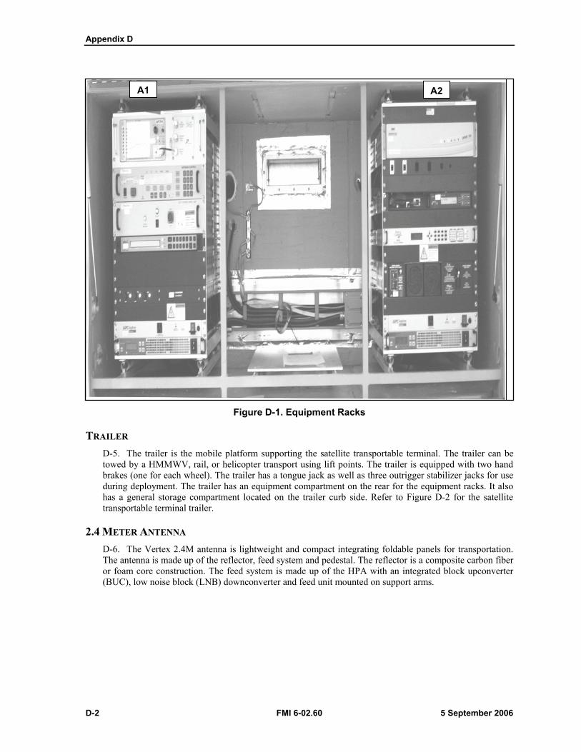
Appendix D
D-2 FMI 6-02.60 5 September 2006
Figure D-1. Equipment Racks
TRAILER D-5. The trailer is the mobile platform supporting the satellite transportable terminal. The trailer can be towed by a HMMWV, rail, or helicopter transport using lift points. The trailer is equipped with two hand brakes (one for each wheel). The trailer has a tongue jack as well as three outrigger stabilizer jacks for use during deployment. The trailer has an equipment compartment on the rear for the equipment racks. It also has a general storage compartment located on the trailer curb side. Refer to Figure D-2 for the satellite transportable terminal trailer.
2.4 METER ANTENNA D-6. The Vertex 2.4M antenna is lightweight and compact integrating foldable panels for transportation. The antenna is made up of the reflector, feed system and pedestal. The reflector is a composite carbon fiber or foam core construction. The feed system is made up of the HPA with an integrated block upconverter (BUC), low noise block (LNB) downconverter and feed unit mounted on support arms.
Space for MRT (Not for Transport)
Space for MRT (Not for Transport)
A2 A1

Ku Band Satellite Transportable Terminal
5 September 2006 FMI 6-02.60 D-3
Figure D-2. Satellite Transportable Terminal Trailer
KU BAND SATELLITE TRANSPORTABLE TERMINAL EQUIPMENT DESCRIPTION
D-7. The Satellite Transportable Terminal has electronic components, mounted in two separate racks (A1 and A2), which provide voice and data connectivity for intratheater or intertheater operations.
SATELLITE TRANSPORTABLE TERMINAL EQUIPMENT RACK A1- ANTENNA CONTROL OR RF EQUIPMENT
D-8. The following is the antenna control or RF equipment which is located in rack A1, on the Ku band trailer:
Spectrum analyzer – PSA-45D. Antenna control unit (ACU) – 123T-DC. Traveling wave tube amplifier control panel. PDU – ACU PDU. 10MHz reference or LNB power – chassis. AC distribution – APC SurgeArrest. Inverter.

Appendix D
D-4 FMI 6-02.60 5 September 2006
Spectrum Analyzer (PSA-45D) D-9. The PSA-45D spectrum analyzer is a small, lightweight analyzer provided with the satellite transportable terminal system. It is used to measure signal strength of the satellite to assist in acquiring an initial satellite signal during setup. It is used for monitoring downlink and uplink L-band signals. It is also used for isolation and resolution of terminal transmit and receive troubles. The spectrum analyzer is used to monitor transmit and receive IF L-band signals.
ACU D-10. The ACU provides manual and automatic antenna pointing and satellite acquisition. It uses the terminal’s GPS and flux compass for location and pointing information. It calculates pointing angles to a given satellite and sends pointing information to the antenna power drive unit. The ACU uses an integrated L-band range tracking receiver to auto track and to acquire a selected satellite. The antenna control unit used on the satellite transportable terminal is a Vertex 123T-DC. This antenna controller is designed for use with elevation over azimuth antennas on mobile satellite uplink vehicles. It automates the process of locating and locking onto a particular satellite.
ACU PDU D-11. The ACU PDU receives drive commands from the ACU and provides drive power to the antenna motors. When the antenna is commanded to move, the PDU receives antenna velocity as it checks limit switch status. As the antenna moves, the PDU relays position data from the resolvers, pointing data from the flux compass, and tilt data from the antenna tilt sensor. The PDU is powered by 90 to 264 VAC, 50/60 Hz +/- 5%.
HPA Control Panel D-12. The control panel is a unit controller for the HPA. A multicolored alarm indicator reports HPA alarms, faults, and communications faults at a glance.
10 MHz Reference or Low Noise Block (LNB) Power Chassis D-13. The 10 MHz reference or LNB power chassis supplies +24 volts direct current (VDC) power and a 10MHz (0+/-1 dBm) reference signal to the LNB. The unit supplies only the 10MHz reference to the BUC powered by the HPA. On the uplink side, the 10 MHz reference chassis inputs the L-band range uplink carriers from the TDMA and FDMA modems and passes them to the BUC. On the downlink side, the unit inputs the L-band range downlink signal from the LNB and passes it to the TDMA and FDMA modems via a 2-way divider. Signal losses through the 10 MHz chassis is minimal. The unit also blocks all DC and reference signals from the modems to the LNB and BUC. The 10 MHz reference chassis is powered by 85 to 264 VAC, 0.52-1.2A, 47 to 63H.
AC Output Distribution D-14. The AC distribution panel is used to provide up to eight switched AC outputs. The AC output power is 120 VAC, 50/60 Hz +/- 5 Hz at 15 amps. Power surge protection, which is designed to handle current surges as high as 13000 amps, is provided for the eight switched outlets.
Inverter D-15. The inverters supply conditioned AC voltage to the HPA and satellite transportable terminal equipment racks A1 and A2. Inverter A1A7 is dedicated to supplying high power requirements to the HPA. Inverter A2A7 supplies power to the equipment racks A1 and A2. The inverters are used to condition AC input voltages or convert DC input voltages to an AC voltage. Input DC voltage range is 20 to 36 VDC (rated at 100A at 18 VDC). Input over current protection is also provided at 140 amps. Each inverter supplies 110 to 120 VAC 50/60 Hz (1500 watts) of output power. Power is drawn from the batteries and inverted to supply electronic equipment power during shore power failure while the APU is started and

Ku Band Satellite Transportable Terminal
5 September 2006 FMI 6-02.60 D-5
brought online. The batteries will support the satellite transportable terminal for twelve minutes. The ECU is not powered while the inverters are running off of the batteries.
SATELLITE TRANSPORTABLE TERMINAL EQUIPMENT RACK A2 – BASEBAND OR SIGNAL MONITOR EQUIPMENT
D-16. The following is the baseband or signal monitor equipment which is located in rack A2, on the Ku band trailer.
TDMA satellite modem. Console interface. FOM shelf (containing media converter and Codem) in JNN only trailer. FDMAsatellite modem (JNN only). AC distribution (PDU). Battery charger. Inverter. Power indicator or DC cutoff switch control.
TDMA IP Modem D-17. The TDMA IP modem is a multi-carrier, multi-rate, TDMA, VSAT-like platform. The TDMA IP modem demodulates the data from the L-band carrier and provides the router and TDMA satellite modem functionality for the terminal.
Console Interface Panel D-18. The console interface panel is used for external user interface to the TDMA IP modem. A user supplied PC can connect the PC’s serial port to the TDMA IP modem via a console cable assembly. Another port is provided for loading DMD-20 modem firmware upgrades.
CDIM (JNN Only) D-19. The CDIM is used to convert data from CDI on fiber optic transport (TFOCA II/100Base-FX) to NRZ on copper transport. The modem is located on the JNN satellite transportable terminal only.
Media Converter D-20. The media converter is used to convert network traffic to and from fiber optic (TFOCA II/100Base-FX) media and copper (10/100BaseT) media.
FDMA Satellite Modem (JNN Only) D-21. The FDMA satellite modem is programmable and provides FDMA functionality for the terminal. The FDMA satellite modem is on the JNN satellite transportable terminal only.
Battery Charger PM-24-20 D-22. The battery charger is used to convert AC power to DC power. The DC power is used to charge the satellite transportable terminal standby batteries. The input voltage for the unit is 85 – 135 VAC, 47 – 63 Hz at 16 amps. The output voltage is 27.2 VDC at 20 amps. Front panel test points are provided for monitoring the DC output voltage.
L-band Combiner or Splitter Assembly and Battery D-23. The L-band splitter assembly contains the downlink 2-way splitter and uplink two-way combiner. The A8 assembly is mounted on the rear of equipment rack A2 and has no controls or indicators. The downlink 2-way divider divides the L-band range signals from the 10 MHz reference chassis LNB power and routes them to the FDMA and TDMA.
Appendix D
D-6 FMI 6-02.60 5 September 2006
D-24. The uplink 2-way combiner combines the two L-Band range signals from the FDMA and TDMA modems and routes them to the 10 MHz reference chassis. This assembly also has a connection point for the battery charger’s temperature sensor.
Inverters D-25. The inverters supply conditioned AC voltage to the HPA, and satellite transportable terminal equipment racks A1 and A2. Inverter A2A7 is totally dedicated to supplying power to the HPA because of its high power requirements. Inverter A1A7 supplies power to equipment racks A1 and A2. The inverters are used to condition AC input voltages or convert DC input voltages to an AC voltage. Input DC voltage range is 20 to 36 VDC (rated at 100A at 18 VDC). Input over current protection is also provided at 140 amps. Each inverter supplies 110 to 120 VAC 50/60 Hz (1500 watts) of output power.
EQUIPMENT POWER UP D-26. The site for the satellite transportable terminal trailer should have a clear view of the area of the sky where the satellite is located. In the Northern hemisphere, a clear view of the Southern sky is needed. In the Southern hemisphere, a clear view of the Northern sky is needed. The location should be a flat, stable location. Check to make sure there are no overhead power lines. An overhead clearance of at least 50 feet is recommended.
D-27. To turn on the equipment in equipment racks A1 and A2 follow the steps below: At the inverter press the ON/OFF switch to the ON position and place the AC Output switch to
the ON position. At the HPA AC indicator and DC cutoff switch control, turn the cutoff switch to the ON
position.
Note. The HPA ON/OFF switch should be ON. HPA will be in filament time delay for three minutes. Verify the HPA fan on bottom of HPA is blowing.
Press the power switch to the ON position at the AC distribution assembly. Press the power switch on the right to the ON position. Verify that the Inverter batteries are
charging. Measure the bottom set of test points and verify that the voltage is 24 - 27 VDC. Set the power switch to the ON (up) position on the PDU. Press power switch to the ON (up) position on the ACU. Press the ON/OFF switch to the ON (up) position on the spectrum analyzer.

Ku Band Satellite Transportable Terminal
5 September 2006 FMI 6-02.60 D-7
D-28. All equipment should be turned on, ensure all indicators are on. Check that the HPA is in standby mode. If any equipment is not on, refer to troubleshooting flowcharts in Section 4 of the STT Operation and Maintenance Manual AN/TSC-167 (V). Refer to Figure D-3 for the trailer block diagram.
Figure D-3. Block Diagram
2PORTTX/RXFEED
400 WATT Ku-BandTWTA with
integrated BUC
TRF
÷
TFOCA-IIFlange Mount
Interface
2.4 METERTRAILER
MOUNTEDANTENNA
HPABUC
LNB
L-Band Spectrum Analyzer
AZ EL POL
Antenna Control Unit Auto Acquire and Auto
Tracking
Digital Tracking Receiver
FOM(Transition Ntwk)
TRAILER SUBSYSTEMS - Air Conditioning - Generator - UPS - Power plug for shore power (Generator or Shore power)
CustomeTFOCA-
Flange Mount
Interface
Tactical Fiber
(4-Strand)100M
LINKWAY Modem
FOM(Codem)
FDMAModem
RS-530
Ethernet
LNB power and 10MHz reference
JNN only(X 10)
TWTAController
DemarcPoint
From MRTCase
2-way
ST Conn
4-way
75? to 50?
÷
Case A Case BTo MRTCase
ST Conn
50?
75?
GPS Rcvr\Compass
DC Pass
DC Pass
X-10dB
Coupler
L-Band Patch

This page intentionally left blank.

5 September 2006 FMI 6-02.60 GlossaryGlossary-1
Glossary
ACRONYMS AND ABBREVIATIONS Acronym Definition
AC alternating current ACU antenna control unit AES Advanced Encryption Standard AIM Advance Integration Module
AO area of operations AOR area of responsibility APU auxiliary power unit
ARFOR Army forces BCP Battle Command Post BCT brigade combat team BDE brigade BITS Battlefield Information Transmission System
BLOS beyond line of sight BN battalion
BNOSC brigade Nodal Operations Security Center BOS battlefield operating system BPS bits per second
BUC block upconverter BVTC Battlefield Video Teleconferencing CAISI CSS Automated Information Systems Interface CBCS Common Baseline Circuit Switches
CDI conditioned diphase CDIM conditioned diphase modem
CDS Compact Digital Switch C-E communications-electronics
CECOM communcations electronics command CFSR contractor field service representatives
CHS common hardware software CM call manager
CND computer network defense CODEC coder/decoder
COMSEC communications security CONUS continental United States
COTS commercial off-the-shelf CP command post
CPN Command Post Node CPP communications patch panel

Glossary
Glossary-2 FMI 6-02.60 5 September 2006
CSS combat service support CSUM Channel Sevice Unit Modem
CT cipher text DC direct current
DCE Data Circuit Equipment DCO dial central office
DCSS Defense Communication Satellite Subsystem DED dedicated encryption device DES Data Encryption Standard
DIBITS digital in-band interswitch trunk signaling DISA Defense Information Systems Agency DISN Defense Information Systems Network
DMAIN Division Main DOD Department of Defense
DPEM Detailed Planning and Engineering Module DRSN Defense Red Switch Network
DS direct support DS3 digital signal level 3
DSCS Defense Satellite Communications System DTAC division tactical
DTE data terminal equipment DTG digital trunk group DSN Defense Switched Network ECU environmental control unit EHF extremely high frequency
FDMA frequency divison multiple access FES forced entry switch
FLEXMUX Flex Multiplexer FO fiber optic
FOM Fiber Optic Modem FMI Field Manual Interim
FMTV family of medium tactical vehicles FTP file transfer protocol
FTSAT Flyaway Tri-band Satellite Terminal FTX field training exercise
GBIC gigabit interface converter GFE governement-furnished equipment GIG Global Information Grid
GMF ground mobile forces GOTS governemnt off-the-shelf
GPP group patch panel

Glossary
5 September 2006 FM 6-02.60 Glossary-3
GPS global positioning system GRE generic router encapsulation
GWL Gateway Link HBCT heavy brigade combat team
HCLOS high capacity line of sight HDSL High-data-rate Digital Subscriber Line
HDSM High Density Service Module HMMWV high-mobility multipurpose wheeled vehicle
HP Hewlett Packard HSD High Speed Data Channel
HSFEC High Speed Error Corrector HVA High Voltage Assembly
IA information assurance IBCT infantry brigade combat team
IDS intrusion detection system IGX ISDN gateway switch INE In-line Network Encryptors IOS internetwork operating system
IP internet protocol ISDN Integrated Services Digital Network
ISYSCON integrated system control JFLCC joint force land component commander JNMS Joint Network Management System
JNN Joint Network Node JNN-N Joint Network Node-Network
JNTC-S Joint Network Transport Capability-Spiral JTF joint task force
JV2020 Joint Vision 2020 JWICS Joint Worldwide Intelligence Communications System
KVM Keyboard, Video and Mouse kW kilowatt
LAN local area network LDR low data rate LED light emitting diode LEN large extension node LMS Lightweight Modular Shelter LNB low noise block LOS line of sight LPI low probability of intercept
MAC maintenance allocation chart Mbps megabytes per second

Glossary
Glossary-4 FMI 6-02.60 5 September 2006
Mbs megabits per second MDMP military decision-making process
MDR medium data rate MHz megahertz
MI military intelligence MILSTAR miltary strategic and tactical relay system
MOS military occupational specialty MP Metal Plate
MRT Master Reference Terminal MSE mobile subscriber equipment
MTOE modified table of organization and equipment MUX multiplexer NCS Node Center Switch NET new equipment training
NETT new equipment training team NETCOM Network Enterprise Technology Command NETOPS network operations
NIPRNET Non-Secure Internet Protocol Router Network NM network management
NMF Network Management Facility NOSC network operations and security center
NRZ non-return-to-zero NSA National Security Agency NSC network support company PBX Private Brnach Exchange
PCMCIA personal computer memory card international association PDU power drive unit PEP power entry panel PLL prescribed load list
PMCS preventative maintenance checks and services PoE Power Over Ethernet
POTS Plain Old Telephone System PRC Primary Rate Card
PT plain text PVS-12 Module PrimeVoice Secure Module
QMUX Quad Multiplexer QoS quality of service
RAU radio access unit RF radio frequency
RSC Regional Service Center RX receive

Glossary
5 September 2006 FM 6-02.60 Glossary-5
S-6 command, control, communications and computers operations (C4 Ops) officer SATCOM satellite communications
SA-TRK symmetrical-asymmetrical trunk module SBCT stryker brigade combat team SCC-2 System Control Center-2 SCPC Space Communications Protocol Standard
SEC Software Engineering Center SEN small extension node SEP signal entry panel SFP small form-factor pluggable SHF super-high frequency
SIPRNET SECRET Internet Protocol Router Network SMART-T Secure Mobile Anti-Jam Reliable Tactical Terminal
SMU switch multiplexer unit SNMP Simple Network Management Protocol
SOP standard operating procedures SSS single shelter switch STE secure telephone equipment
STEP standard tactical entry point STIG security technical implementation guide
STP Shielded Twisted Pair STRATCOM Strategic Command
TAC tactical command post TACLANE tactical fastlane
TACSAT tactical satellite TCP/IP transmission control protocol/internet protocol
TDM time division multiplexer TDMA time division multiple access
TED trunk ecryption device TFOCA Tactical Fiber Optical Cable Assembly
TFTP Trivial File Transfer Protocol TGRS Transportable Ground Receive Suite
THSDN Tactical High Speed Data Network TI Tactical Internet
TIMS Tactical Information Management System TK Tool Kit
TOC tactical operations center TRC Transmissions Resource Control
TRI-TAC Tri-Service Tactical Communications Program Trojan SPIRIT Trojan Special Purpose Integrated Remote Intelligence Terminal
TROPO trophospheric scatter

Glossary
Glossary-6 FMI 6-02.60 5 September 2006
TS/SCI top secret/sensitive compartmented information TTP tactics, techniques, and procedures
TUID Tactical User Identification TX transmit UA unit of action
UHF ultrahigh frequency UHN Unit Hub Node
ULLS unit level logistics system UPS uninterruptible power source
VAC volts, alternating current VDC volts, direct current VoIP Voice Over Internet Protocol VPN Virtual Private Network
VSAT very small aperture terminal VTC video teleconferencing
WAN wide-area network WIC WAN Interface Card
WIN-T Warfighter Information Network-Tactical WMI Warfighter Machine Interface

5 September 2006 FMI 6-02.60 References-1
References These are the sources quoted or paraphrased in this publication. Army Publications
DA Form 2028, Recommended Changes to Publications and Blank Forms. FM 24-1, Command, Control, Communications and Computers (C4) Operations, 15 October 1990
(will be revised as FM 6-02). FM 24-69, Signal Digital Equipment Procedural Guide, (will be revised as FM 6-02.69). FMI 6-02.45 Signal Support to Theater Operations, 12 April 2004. FMI 11-43, Tactical Signal Leaders Guide, 12 June 1995 (will be revised as FM 6-02.43). FMI 11-50, LandWarNet Operations in the CORPS, Division, and Brigade Units, 4 April 1991 (will be
revised as FMI 6-02.50). FMI 11-57, Tactical Wire and cable Techniques, 22 August 1966 (will be revised as FMI 6-02.57). FMI 11-71, Network Operations (NETOPS), (will be revised as FMI 6-02.71). FMI 24-2, Army Electromagnetic Spectrum Management Operations, 21 August 1991 (will be revised
as FMI 6-02-70).

This page intentionally left blank.

5 September 2006 FMI 6-02.60 Index-1
Index
A Advanced Encryption
Standard, (AES), B-18 AN/TRC-170, 2-7 AN/TRC-190, 2-7, 3-4 AN/TSC-85, 2-5 AN/TSC-93, 2-5 AN/TTC-39D, 2-8 AN/TTC-56, 2-9 AN/USC-60A, 2-7
B battalion, 2-1, 2-2, 2-4, 3-1, 3-
2, 3-4, 3-5, 4-3, C-4, C-7, C-12, D-1
BCT, 1-3, 2-1, 2-2, 2-4, 2-8, 2-9, 3-1, 3-2, 3-3, 3-4, B-1, B-61, C-1, C-4, C-7, C-23, D-1
beyond line of sight, (BLOS), 1-2, 2-4, 2-7
BLOS interfacing capabilities, 2-4
bridge to future networks, 1-2 brigade combat team, (BCT),
1-2, 3-3 BVTC/BITS, C-5
C Cable System Installer
Maintainer, 3-2 CAISI, 1-2 Call Manager Express, C-7 call manager, (CM), A-4, A-5,
B-48, B-50, C-6 Certificate Authority Server, B-
18 combat service support (CSS)
Satellite Communications, 1-2
Combat Service Support (CSS) satellite communications (SATCOM), 1-2
Command Post Node Component Listing, Startup, and Maintenance Procedures, C-1
command post node, (CPN), 2-1, 2-2, 2-9, 3-2, 3-5, 4-1, B-18, C-1, C-7, C-10, C-12, C-15, C-20, C-23, D-1
Command Post Support Section, 3-5
commercial off-the-shelf, (COTS), 1-2, 2-7, 4-1, A-3, A-4, A-5, B-48, B-54, B-61, C-2, C-3, C-8, C-9, C-10, C-23
communications security, (COMSEC), 2-1, A-2, B-2
Configuring the Battalion Router Case, C-15
Configuring The Virtual Private Network Router, C-20
Connecting the BN CPN LOS Case, C-12
Connecting the CPN, C-12 Connecting The Division,
Brigade, and BCT Interface Cases, C-4
Connectivity to Current Networks, 2-8
D data, 2-1, 2-2, 2-3, 2-4, 2-5, 2-
7, 2-8, 2-9, 3-3, 3-4, 3-5, A-2, A-3, A-4, A-5, A-6, B-4, B-5, B-6, B-11, B-12, B-13, B-16, B-18, B-19, B-24, B-28, B-46, B-48, B-55, B-56, B-57, B-58, B-61, C-1, C-3, C-7, C-8, C-10, C-11, C-12, D-1, D-4, D-5
Data Encryption Standard, (DES), C-3, C-9
Defense Information Systems Network, (DISN), 2-1, 2-2, 2-4, 2-7, 2-8
Defense Red Switch Network, (DRSN), 2-3, 2-4
Defense Switched Network, (DSN), 2-1, 2-2, 2-4, 2-7, A-5
Department of Defense (DOD), 1-1
Division, 3-1 Division Main, (DMAIN), 4-2, 4-
3 division network, operations,
and security center, 3-2 Domain Workstations, A-3
E Employment of the Joint
Network Node-Network at the Division, Brigade and Battalion Level, 3-1
Equipment Power Up, D-6
F Flyaway Tri-Band Satellite
Terminal, (FTSAT), 2-4, 2-7 forced entry switch, (FES), 2-8 frequency division multiple
access, (FDMA), 2-1, 2-2, 2-4, 2-9, A-1, A-3, A-5, A-6, B-61, C-1, D-1, D-4, D-5, D-6
G gigabyte interface converter, C-
3 Global Information Grid, 1-1 Global Information Grid, (GIG),
1-1, 2-1, 2-2, 2-3, 2-7, 2-8, 2-9, 3-5, C-1
government off-the-shelf, (GOTS), 1-2, 4-1
ground mobile forces, (GMF), 2-4, 2-5, A-4, A-6, B-58
H heavy brigade combat team, 3-
3 high capacity line of sight,
(HCLOS), 2-7, 3-2, 3-4
I integrated system control,
(ISYSCON V4), 4-2, 4-3 Interface Case A Components,
C-1 Interface Case B Components,
C-3 intrusion detection system,
(IDS), 4-2, 4-3, B-4, B-5, B-28
J JNTC-S, 1-1, 1-2, 1-4 joint force land component
command, 1-2 Joint Network Management
System, 3-2

Index
Index-2 FMI 6-02.60 5 September 2006
Joint Network Node Components and Connectivity, B-1
Joint Network Node Section, 3-4
Joint Network Node, (JNN), 1-3, 2-2, 2-3, 2-4, 2-7, 2-8, 2-9, 3-2, 3-4, 3-5, 4-1, 4-2, B-1, B-2, B-3, B-18, B-24, B-48, B-53, B-54, B-55, B-57, B-58, B-61, C-1, C-3, C-4, C-5, C-12, C-15, D-1, D-5
Joint Network Node-Network, 2-1
Joint Network Node-Network, (JNN-N), v, 1-1, 1-2, 2-1, 3-1, 4-1
Joint Network Transport Capabilities - Spiral, 1-2
joint task force, 1-2 JWICS, 1-3
K KIV-19A TED, C-11 Ku band, 1-2, 2-1, 2-2, 2-4, 2-
7, 2-9, 3-5, A-6, B-58, B-61, C-1, C-12, D-1, D-3, D-5
Ku Band Satellite Terminal, 2-4 Ku Band Satellite
Transportable Terminal Capabilities, D-1
Ku Band Satellite Transportable Terminal Equipment Description, D-3
Ku modems, 2-4
L LandWarNet, 1-1 LEN, 2-8 LOS, 2-4, 2-7, C-1, C-7, C-10,
C-11, C-12 LOS Transit Case Equipment,
C-10
M MDMP, 4-2 MOS 25N, 3-1, 3-4, B-61 MSE, 2-3, 2-8, B-53, C-11, C-
18
N National Security Agency, 1-3 NCS, 2-8 NETOPS, 3-1, 3-2, 4-2, 4-3, B-
24 Network Description, 2-1
Network Management, 3-1, 3-2, 4-1, 4-2, 4-3, A-2, B-58
Network management at the brigade, 4-3
Network Management Components, 4-1
Network monitoring management, 4-2
NIPRNET, 1-2, 2-1, 2-2, 2-3, 2-4, 2-9, 3-3, 3-4, 4-2, 4-3, A-2, A-3, A-4, A-5, B-2, B-3, B-4, B-5, B-6, B-11, B-18, B-19, B-24, B-28, B-29, B-36, B-48, B-49, B-50, B-55, B-58, B-61, C-1, C-3, C-4, C-10, C-13, C-14, C-15
NIPRNET Connection Points, C-4
Nodal Network Systems Operator-Maintainer, 3-1
Node Center Switch, 2-8 Non Secure Internet Protocol
Router Network, 1-2 NSA, 1-3
R Router Transit Case, C-8
S Satellite Transportable
Terminal Equipment Rack A1, D-3
Satellite Transportable Terminal Equipment Rack A2, D-5
signal entry panel, 2-4, B-58, C-5
Signal Support System Specialist, 3-2
SIPRNET, 2-1, 2-2, 2-3, 2-4, 2-9, 3-3, 3-4, 4-2, 4-3, A-2, A-3, A-4, A-5, B-2, B-3, B-11, B-18, B-28, B-29, B-36, B-45, B-48, B-50, B-53, B-55, B-57, B-58, B-61, C-1, C-3, C-4, C-5, C-6, C-8, C-9, C-13, C-14, C-15
SIPRNET Domain, A-4 SMART-T, 2-4, 2-6 Space Communications
Protocol Standard, C-2, C-8 standard tactical entry point, 2-
1 STEP, 2-1, 2-2, 2-4, 2-5, 2-7,
3-1, 3-2, A-5, B-55
T TACSAT, 2-5, 3-1, 3-2, 3-4 tactical command post, 3-2 TDMA, 2-1, 2-2, 2-4, 2-9, 3-1,
3-5, A-1, A-6, B-5, B-18, B-22, B-46, B-61, C-1, C-7, C-9, C-10, D-1, D-4, D-5, D-6
The Joint Network Transport Capabilities - Spiral, 1-1
time division multiple access, 2-1
Transit Cases, B-61 Transmission Capabilities, 2-3 TRC, 2-1, 2-3, 2-7, 3-4, 3-5, 4-
1, 4-2, A-5, A-6, B-2, B-48, B-54, B-55, B-56, B-57, B-58
TRI-TAC, 2-8, B-53, C-11 Trojan SPIRIT, 1-3 TROPO, 2-7 Trunk Encryption Device, A-6 TS/SCI, 1-3, 2-4 TUID, 2-9, A-5, B-54, C-6
U UHN, 2-1, 2-2, 2-3, 2-4, 3-1, 3-
2, 3-5, 4-1, 4-2, A-1, A-2, A-4, A-5, A-6
UHN Component Listing, A-1 ULLS, 1-2 Uninterruptible Power Supply,
2-9, C-12 Unit Hub Node
Baseband Shelter, 2-1 UPS, 2-9, C-1, C-4, C-7, C-12,
C-13, C-14 UPS Case, C-4
V Vantage, 2-8, A-4, A-5, B-2, B-
28, B-48, B-53, B-54, B-56, B-58, C-6
Virtual Private Network, B-18 voice, 2-1, 2-2, 2-3, 2-4, 2-5, 2-
8, 2-9, 3-3, 3-4, 3-5, A-2, A-3, A-5, A-6, B-13, B-17, B-28, B-36, B-48, B-50, B-53, B-55, B-56, B-61, C-1, C-2, C-5, C-6, C-7, C-10, C-11, C-12, C-16, C-18, C-19, D-1
Voice Cases, C-5 VoIP, 2-2, 2-9, A-3, A-5, B-11,
B-48, B-53, C-1, C-3, C-6, C-7, C-8, C-9

Index
5 September 2006 FM 6-02.60 Index-3
VPN, B-3, B-5, B-14, B-15, B-16, B-18, B-19, B-28, B-46, C-3, C-7, C-9, C-10, C-21
VPN Transit Case Equipment, C-9
W Warfighter Information
Network-Tactical, 1-2 Warfighter Machine Interface,
4-1
WIN-T, 1-2 WMI, 4-1

This page intentionally left blank.

FMI 6-02.60 5 September 2006
Expires 5 September 2008
By order of the Secretary of the Army:
PETER J. SCHOOMAKER General, United States Army
Chief of Staff
Official:
JOYCE E. MORROW Administrative Assistant to the Secretary of the Army 0622701 DISTRIBUTION: Active Army, Army National Guard, and U.S. Army Reserve: Not to be distributed. Electronic media only.

PIN: 083500-000