table of contents - fordservicecontent.com · supplement usa english (fus) ... board diagnostics...
TRANSCRIPT
Introduction 3
Instrumentation 8Warning and control lights 8Gauges 11
Lights 14Headlamps 14Bulb replacement 15
Driver controls 16Windshield wiper/washer control 16Steering wheel adjustment 16Speed control 17
Driving 20Starting 20Brakes 23Transmission operation 27Vehicle loading 31Trailer towing 36
Roadside emergencies 39Getting roadside assistance 39Hazard flasher switch 40Fuel pump shut-off switch 40Fuses and relays 41Changing tires 48Jump starting 52Wrecker towing 56
2004 Motorhome (mot)SupplementUSA English (fus)
Table of contents
1

Customer assistance 57Reporting safety defects (U.S. only) 65
Cleaning 66
Maintenance and specifications 67Engine compartment 68Engine oil 69Battery 71Fuel information 79Air filter(s) 95Part numbers 109Refill capacities 110Lubricant specifications 112
Index 116
All rights reserved. Reproduction by any means, electronic or mechanicalincluding photocopying, recording or by any information storage and retrievalsystem or translation in whole or part is not permitted without writtenauthorization from Ford Motor Company. Ford may change the contents withoutnotice and without incurring obligation.
Copyright © 2003 Ford Motor Company
2004 Motorhome (mot)SupplementUSA English (fus)
Table of contents
2
CALIFORNIA Proposition 65 Warning
WARNING: Engine exhaust, some of its constituents, andcertain vehicle components contain or emit chemicals known to
the State of California to cause cancer and birth defects or otherreproductive harm. In addition, certain fluids contained in vehicles andcertain products of component wear contain or emit chemicals knownto the State of California to cause cancer and birth defects or otherreproductive harm.
CONGRATULATIONSCongratulations on acquiring your new Ford. Please take the time to getwell acquainted with your vehicle by reading this handbook. The moreyou know and understand about your vehicle, the greater the safety andpleasure you will derive from driving it.
For more information on Ford Motor Company and its products visit thefollowing website:
• In the United States: www.ford.com
• In Canada: www.ford.ca
• In Australia: www.ford.com.au
• In Mexico: www.ford.com.mx
Additional owner information is given in separate publications.
This Owner’s Guide describes every option and model variant availableand therefore some of the items covered may not apply to yourparticular vehicle. Furthermore, due to printing cycles it may describeoptions before they are generally available.
Remember to pass on the Owner’s Guide when reselling the vehicle. It isan integral part of the vehicle.
Fuel pump shut-off switch In the event of an accident thesafety switch will automatically cut off the fuel supply to the
engine. The switch can also be activated through sudden vibration (e.g.collision when parking). To reset the switch, refer to the Fuel pumpshut-off switch in the Roadside Emergencies chapter.
2004 Motorhome (mot)SupplementUSA English (fus)
Introduction
Introduction
3
SAFETY AND ENVIRONMENT PROTECTION
Warning symbols in this guide
How can you reduce the risk of personal injury and prevent possibledamage to others, your vehicle and its equipment? In this guide, answersto such questions are contained in comments highlighted by the warningtriangle symbol. These comments should be read and observed.
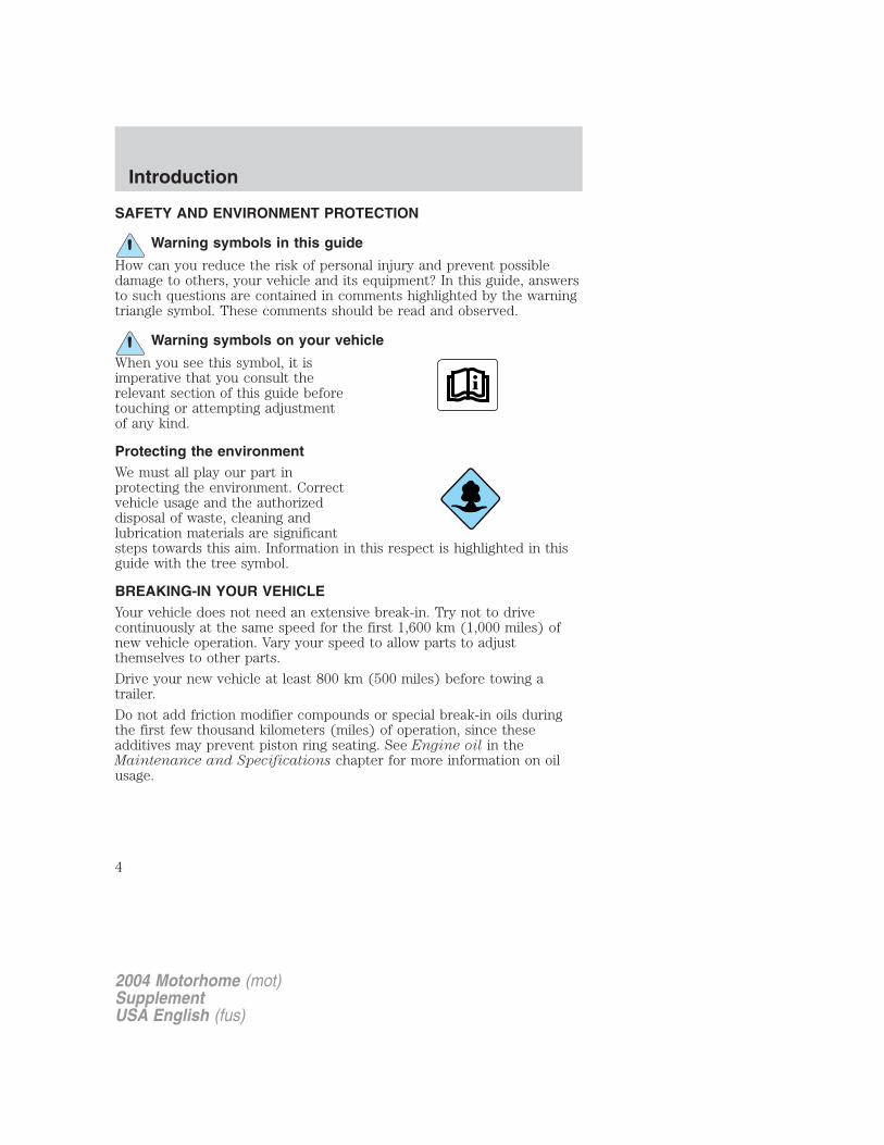
Warning symbols on your vehicle
When you see this symbol, it isimperative that you consult therelevant section of this guide beforetouching or attempting adjustmentof any kind.
Protecting the environmentWe must all play our part inprotecting the environment. Correctvehicle usage and the authorizeddisposal of waste, cleaning andlubrication materials are significantsteps towards this aim. Information in this respect is highlighted in thisguide with the tree symbol.
BREAKING-IN YOUR VEHICLEYour vehicle does not need an extensive break-in. Try not to drivecontinuously at the same speed for the first 1,600 km (1,000 miles) ofnew vehicle operation. Vary your speed to allow parts to adjustthemselves to other parts.
Drive your new vehicle at least 800 km (500 miles) before towing atrailer.
Do not add friction modifier compounds or special break-in oils duringthe first few thousand kilometers (miles) of operation, since theseadditives may prevent piston ring seating. See Engine oil in theMaintenance and Specifications chapter for more information on oilusage.
2004 Motorhome (mot)SupplementUSA English (fus)
Introduction
4
SPECIAL NOTICES
Emission warrantyThe New Vehicle Limited Warranty includes Bumper-to-BumperCoverage, Safety Restraint Coverage, Corrosion Coverage, and 6.0LPower Stroke Diesel Engine Coverage. In addition, your vehicle is eligiblefor Emissions Defect and Emissions Performance Warranties. For adetailed description of what is covered and what is not covered, refer tothe Warranty Guide that is provided to you along with your Owner’sGuide.
Notice to owners of Class A Motorhome VehiclesThe Ford Motorhome Chassis is not suitable for producing ambulances orschool buses. In addition, Ford urges manufacturers to follow therecommendations of the Ford Incomplete Vehicle Manual, Ford TruckBody Builder’s Layout Book and other pertinent supplements.
Notification of delayed warranty start date and accumulatedmileageVerify that your recreational vehicle dealer has submitted a Notificationof Delayed Warranty Start Date and Accumulated Mileage (FCS 900) toFord Motor Company.
2004 Motorhome (mot)SupplementUSA English (fus)
Introduction
5
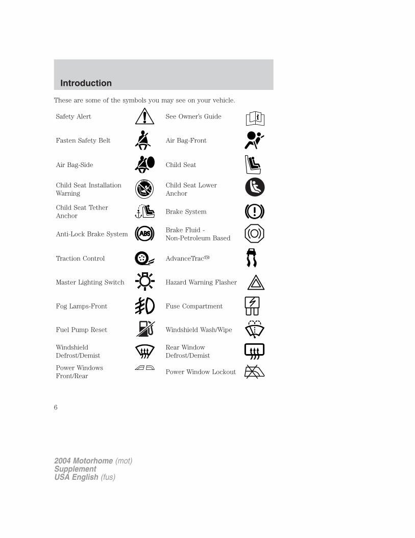
These are some of the symbols you may see on your vehicle.
Safety Alert See Owner’s Guide
Fasten Safety Belt Air Bag-Front
Air Bag-Side Child Seat
Child Seat InstallationWarning
Child Seat LowerAnchor
Child Seat TetherAnchor
Brake System
Anti-Lock Brake SystemBrake Fluid -Non-Petroleum Based
Traction Control AdvanceTrac�
Master Lighting Switch Hazard Warning Flasher
Fog Lamps-Front Fuse Compartment
Fuel Pump Reset Windshield Wash/Wipe
WindshieldDefrost/Demist
Rear WindowDefrost/Demist
Power WindowsFront/Rear
Power Window Lockout
2004 Motorhome (mot)SupplementUSA English (fus)
Introduction
6

Child Safety DoorLock/Unlock
Interior LuggageCompartment ReleaseSymbol
Panic Alarm Engine Oil
Engine CoolantEngine CoolantTemperature
Do Not Open When Hot Battery
Avoid Smoking, Flames,or Sparks
Battery Acid
Explosive Gas Fan Warning
Power Steering FluidMaintain Correct FluidLevel
MAX
MIN
Emission System Engine Air Filter
Passenger CompartmentAir Filter
Jack
Check fuel cap Low tire warning
2004 Motorhome (mot)SupplementUSA English (fus)
Introduction
7
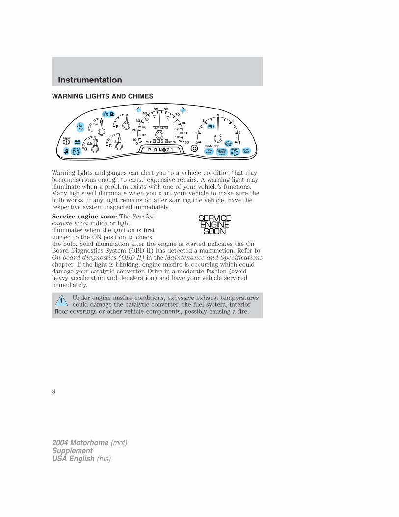
WARNING LIGHTS AND CHIMES
Warning lights and gauges can alert you to a vehicle condition that maybecome serious enough to cause expensive repairs. A warning light mayilluminate when a problem exists with one of your vehicle’s functions.Many lights will illuminate when you start your vehicle to make sure thebulb works. If any light remains on after starting the vehicle, have therespective system inspected immediately.
Service engine soon: The Serviceengine soon indicator lightilluminates when the ignition is firstturned to the ON position to checkthe bulb. Solid illumination after the engine is started indicates the OnBoard Diagnostics System (OBD-II) has detected a malfunction. Refer toOn board diagnostics (OBD-II) in the Maintenance and Specificationschapter. If the light is blinking, engine misfire is occurring which coulddamage your catalytic converter. Drive in a moderate fashion (avoidheavy acceleration and deceleration) and have your vehicle servicedimmediately.
Under engine misfire conditions, excessive exhaust temperaturescould damage the catalytic converter, the fuel system, interior
floor coverings or other vehicle components, possibly causing a fire.
F
E
C
H
H
L
18
8 P R N 2 1
LOWFUEL
BRAKE
!
BRAKE
! + - + -0 0 0
0 0 0 0 0 0
0
50 60
70
20
100
30
40
80
90
100
20
40
60
80 100
120
140
180
MPH km/h
1
0
2
RPMx1000
3
4
5
6
SERVICEENGINESOON
ABS
FUELRESET
DOORAJAR
BRAKE
SERVICEENGINESOON
2004 Motorhome (mot)SupplementUSA English (fus)
Instrumentation
Instrumentation
8
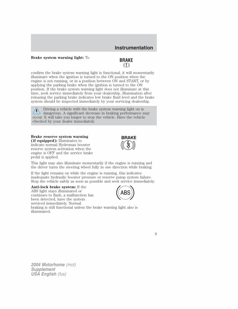
Brake system warning light: To
confirm the brake system warning light is functional, it will momentarilyilluminate when the ignition is turned to the ON position when theengine is not running, or in a position between ON and START, or byapplying the parking brake when the ignition is turned to the ONposition. If the brake system warning light does not illuminate at thistime, seek service immediately from your dealership. Illumination afterreleasing the parking brake indicates low brake fluid level and the brakesystem should be inspected immediately by your servicing dealership.
Driving a vehicle with the brake system warning light on isdangerous. A significant decrease in braking performance may
occur. It will take you longer to stop the vehicle. Have the vehiclechecked by your dealer immediately.
Brake reserve system warning(if equipped): Illuminates toindicate normal Hydromax boosterreserve system activation when theengine is OFF and the service brakepedal is applied.
This light may also illuminate momentarily if the engine is running andthe driver turns the steering wheel fully in one direction while braking.
If the light remains on while the engine is running, this indicatesinadequate hydraulic booster pressure or reserve pump system failure.Stop the vehicle safely as soon as possible and seek service immediately.
Anti-lock brake system: If theABS light stays illuminated orcontinues to flash, a malfunction hasbeen detected, have the systemserviced immediately. Normalbraking is still functional unless the brake warning light also isilluminated.
BRAKE
ABS
2004 Motorhome (mot)SupplementUSA English (fus)
Instrumentation
9
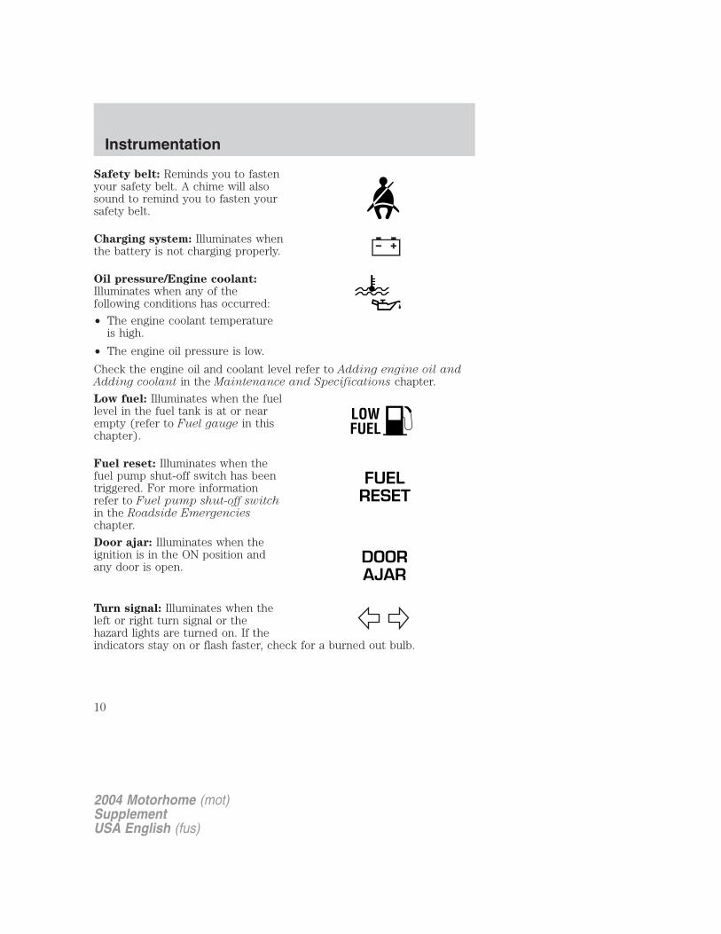
Safety belt: Reminds you to fastenyour safety belt. A chime will alsosound to remind you to fasten yoursafety belt.
Charging system: Illuminates whenthe battery is not charging properly.
Oil pressure/Engine coolant:Illuminates when any of thefollowing conditions has occurred:
• The engine coolant temperatureis high.
• The engine oil pressure is low.
Check the engine oil and coolant level refer to Adding engine oil andAdding coolant in the Maintenance and Specifications chapter.
Low fuel: Illuminates when the fuellevel in the fuel tank is at or nearempty (refer to Fuel gauge in thischapter).
Fuel reset: Illuminates when thefuel pump shut-off switch has beentriggered. For more informationrefer to Fuel pump shut-off switchin the Roadside Emergencieschapter.
Door ajar: Illuminates when theignition is in the ON position andany door is open.
Turn signal: Illuminates when theleft or right turn signal or thehazard lights are turned on. If theindicators stay on or flash faster, check for a burned out bulb.
LOWFUEL
FUELRESET
DOORAJAR
2004 Motorhome (mot)SupplementUSA English (fus)
Instrumentation
10
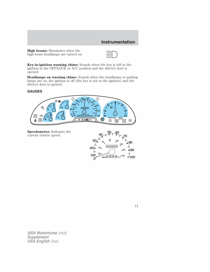
High beams: Illuminates when thehigh beam headlamps are turned on.
Key-in-ignition warning chime: Sounds when the key is left in theignition in the OFF/LOCK or ACC position and the driver’s door isopened.
Headlamps on warning chime: Sounds when the headlamps or parkinglamps are on, the ignition is off (the key is not in the ignition) and thedriver’s door is opened.
GAUGES
Speedometer: Indicates thecurrent vehicle speed.
F
E
C
H
H
L
18
8 P R N 2 1
LOWFUEL
BRAKE
!
+ - + -0 0 0
0 0 0 0 0 0
0
50 60
70
20
100
30
40
80
90
100
20
40
60
80 100
120
140
180
MPH km/hBRAKE
!
1
0
2
RPMx1000
3
4
5
6
SERVICEENGINESOON
ABS
FUELRESET
DOORAJAR
BRAKE
2004 Motorhome (mot)SupplementUSA English (fus)
Instrumentation
11

Engine coolant temperaturegauge: Indicates engine coolanttemperature. At normal operatingtemperature, the needle will be inthe normal range (between “H” and“C”). If it enters the red section,the engine is overheating. Stopthe vehicle as soon as safelypossible, switch off the engineand let the engine cool.
Never remove the coolant reservoir cap while the engine isrunning or hot.
Odometer: Registers the totalkilometers (miles) of the vehicle.
Trip odometer: Registers thekilometers (miles) of individualjourneys. To reset, depress thecontrol.
Tachometer: Indicates the enginespeed in revolutions per minute.Driving with your tachometerpointer continuously at the top ofthe scale may damage the engine.
H
C
2004 Motorhome (mot)SupplementUSA English (fus)
Instrumentation
12
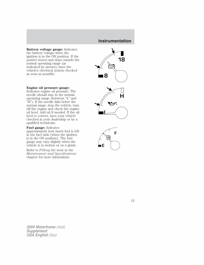
Battery voltage gauge: Indicatesthe battery voltage when theignition is in the ON position. If thepointer moves and stays outside thenormal operating range (asindicated by arrows), have thevehicle’s electrical system checkedas soon as possible.
Engine oil pressure gauge:Indicates engine oil pressure. Theneedle should stay in the normaloperating range (between “L” and“H”). If the needle falls below thenormal range, stop the vehicle, turnoff the engine and check the engineoil level. Add oil if needed. If the oillevel is correct, have your vehiclechecked at your dealership or by aqualified technician.
Fuel gauge: Indicatesapproximately how much fuel is leftin the fuel tank (when the ignitionis in the ON position). The fuelgauge may vary slightly when thevehicle is in motion or on a grade.
Refer to Filling the tank in theMaintenance and Specificationschapter for more information.
8
18
L
H
2004 Motorhome (mot)SupplementUSA English (fus)
Instrumentation
13
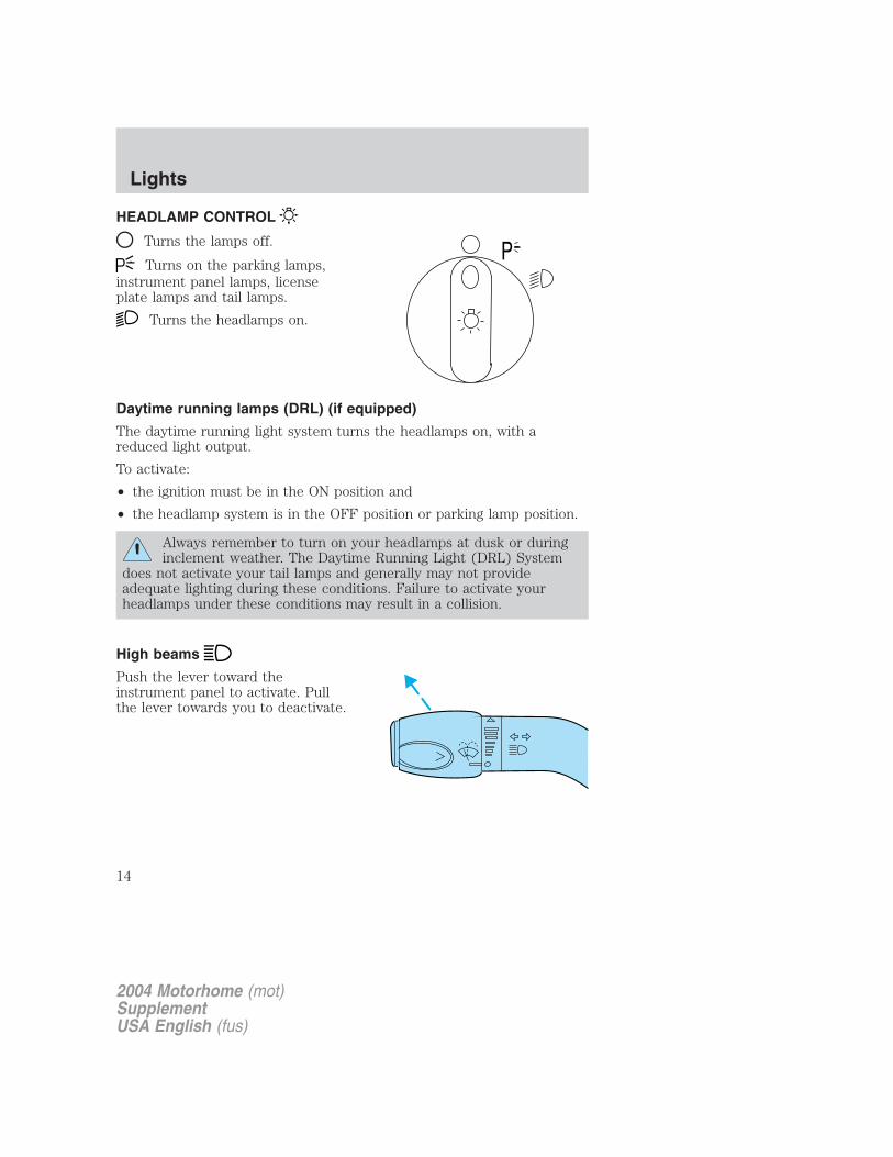
HEADLAMP CONTROL
Turns the lamps off.
Turns on the parking lamps,instrument panel lamps, licenseplate lamps and tail lamps.
Turns the headlamps on.
Daytime running lamps (DRL) (if equipped)
The daytime running light system turns the headlamps on, with areduced light output.
To activate:
• the ignition must be in the ON position and
• the headlamp system is in the OFF position or parking lamp position.
Always remember to turn on your headlamps at dusk or duringinclement weather. The Daytime Running Light (DRL) System
does not activate your tail lamps and generally may not provideadequate lighting during these conditions. Failure to activate yourheadlamps under these conditions may result in a collision.
High beams
Push the lever toward theinstrument panel to activate. Pullthe lever towards you to deactivate.
P
2004 Motorhome (mot)SupplementUSA English (fus)
Lights
Lights
14
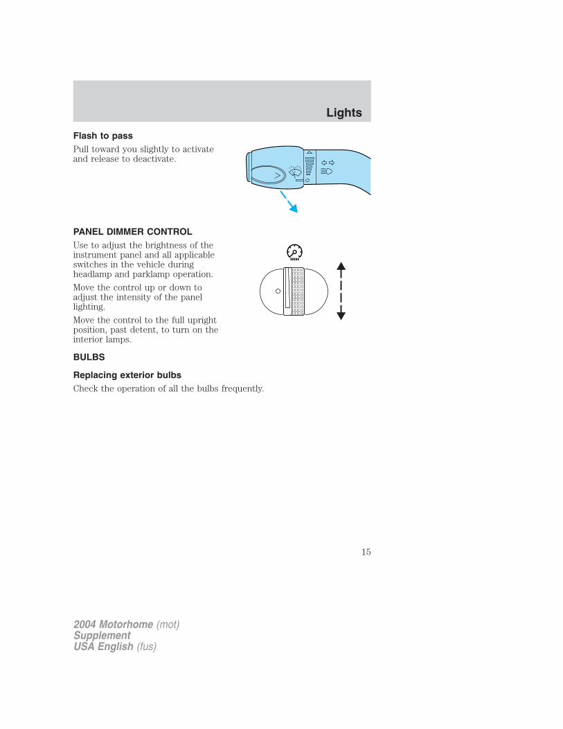
Flash to passPull toward you slightly to activateand release to deactivate.
PANEL DIMMER CONTROLUse to adjust the brightness of theinstrument panel and all applicableswitches in the vehicle duringheadlamp and parklamp operation.
Move the control up or down toadjust the intensity of the panellighting.
Move the control to the full uprightposition, past detent, to turn on theinterior lamps.
BULBS
Replacing exterior bulbsCheck the operation of all the bulbs frequently.
2004 Motorhome (mot)SupplementUSA English (fus)
Lights
15
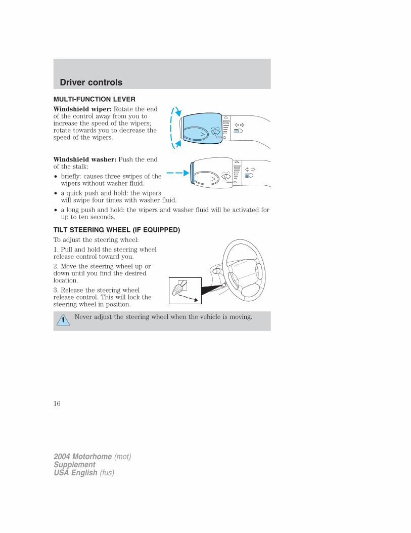
MULTI-FUNCTION LEVERWindshield wiper: Rotate the endof the control away from you toincrease the speed of the wipers;rotate towards you to decrease thespeed of the wipers.
Windshield washer: Push the endof the stalk:
• briefly: causes three swipes of thewipers without washer fluid.
• a quick push and hold: the wiperswill swipe four times with washer fluid.
• a long push and hold: the wipers and washer fluid will be activated forup to ten seconds.
TILT STEERING WHEEL (IF EQUIPPED)To adjust the steering wheel:
1. Pull and hold the steering wheelrelease control toward you.
2. Move the steering wheel up ordown until you find the desiredlocation.
3. Release the steering wheelrelease control. This will lock thesteering wheel in position.
Never adjust the steering wheel when the vehicle is moving.
2004 Motorhome (mot)SupplementUSA English (fus)
Driver controls
Driver controls
16
SPEED CONTROL (IF EQUIPPED)With speed control set, you can maintain a speed of 48 km/h (30 mph)or more without keeping your foot on the accelerator pedal. Speedcontrol does not work at speeds below 48 km/h (30 mph).
Do not use the speed control in heavy traffic or on roads thatare winding, slippery or unpaved.
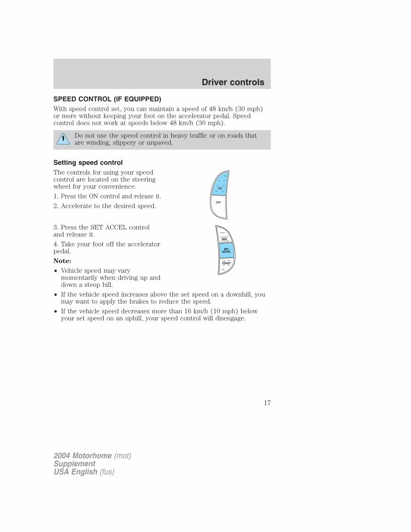
Setting speed controlThe controls for using your speedcontrol are located on the steeringwheel for your convenience.
1. Press the ON control and release it.
2. Accelerate to the desired speed.
3. Press the SET ACCEL controland release it.
4. Take your foot off the acceleratorpedal.
Note:
• Vehicle speed may varymomentarily when driving up anddown a steep hill.
• If the vehicle speed increases above the set speed on a downhill, youmay want to apply the brakes to reduce the speed.
• If the vehicle speed decreases more than 16 km/h (10 mph) belowyour set speed on an uphill, your speed control will disengage.
RES
SETACCEL
COAST
2004 Motorhome (mot)SupplementUSA English (fus)
Driver controls
17
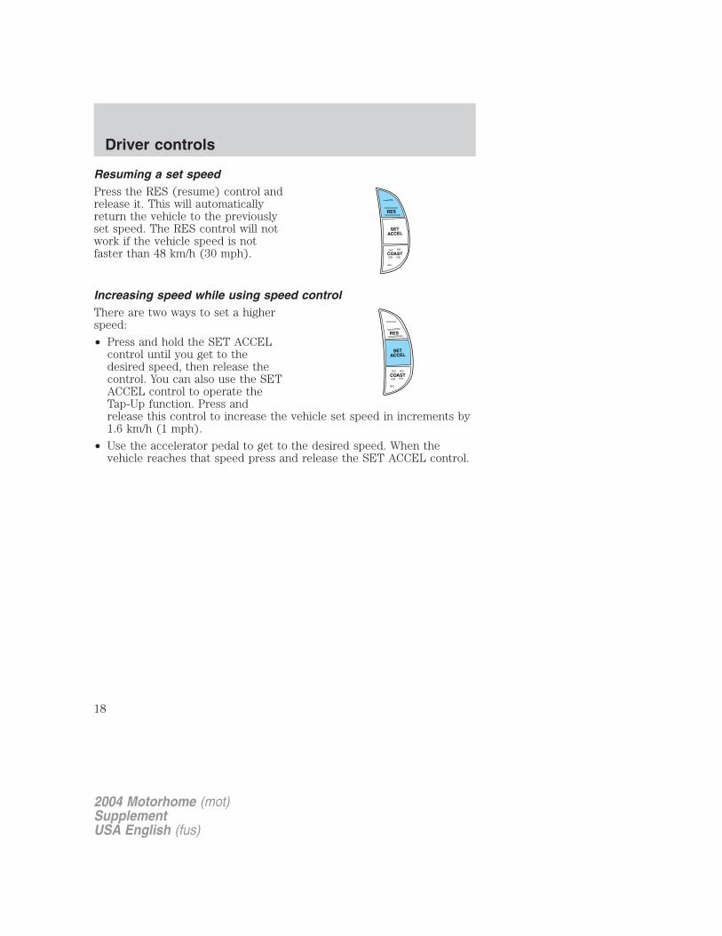
Resuming a set speedPress the RES (resume) control andrelease it. This will automaticallyreturn the vehicle to the previouslyset speed. The RES control will notwork if the vehicle speed is notfaster than 48 km/h (30 mph).
Increasing speed while using speed controlThere are two ways to set a higherspeed:
• Press and hold the SET ACCELcontrol until you get to thedesired speed, then release thecontrol. You can also use the SETACCEL control to operate theTap-Up function. Press andrelease this control to increase the vehicle set speed in increments by1.6 km/h (1 mph).
• Use the accelerator pedal to get to the desired speed. When thevehicle reaches that speed press and release the SET ACCEL control.
RES
SETACCEL
COAST
RES
SETACCEL
COAST
2004 Motorhome (mot)SupplementUSA English (fus)
Driver controls
18
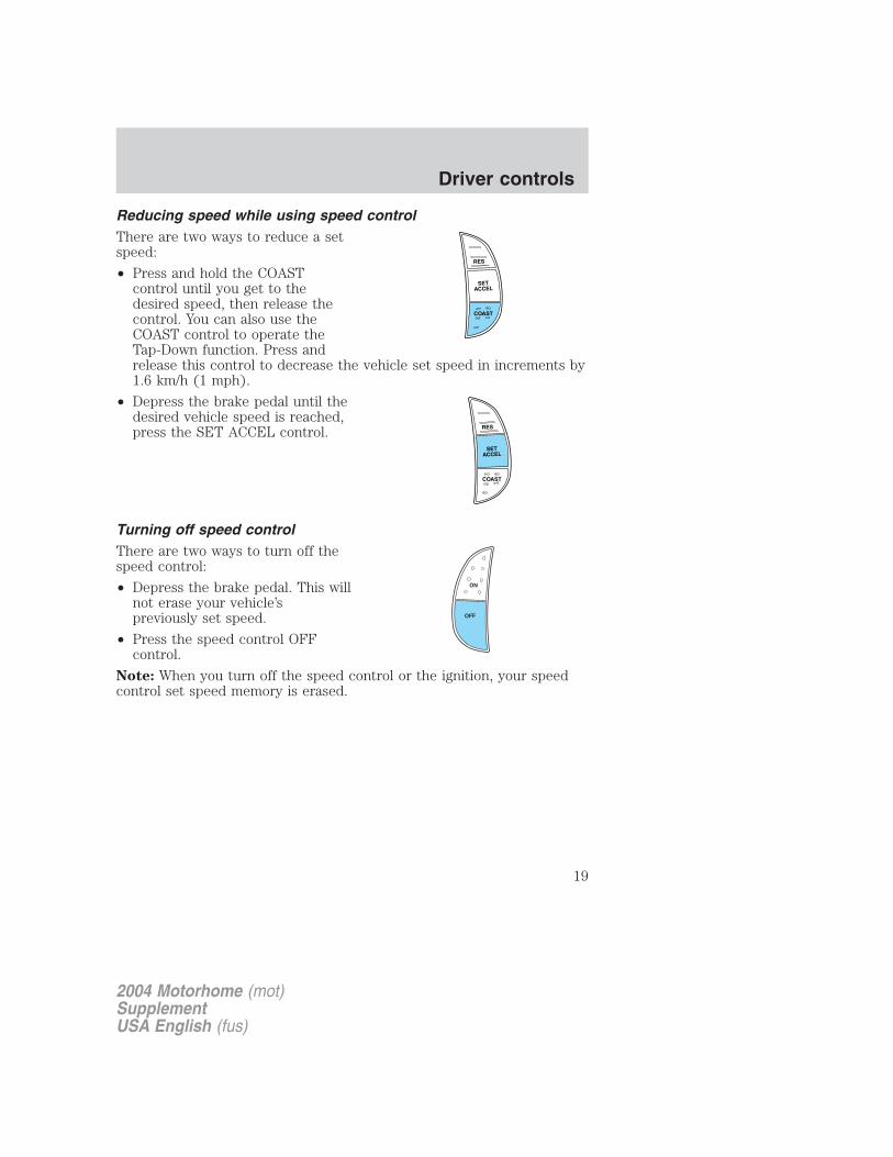
Reducing speed while using speed controlThere are two ways to reduce a setspeed:
• Press and hold the COASTcontrol until you get to thedesired speed, then release thecontrol. You can also use theCOAST control to operate theTap-Down function. Press andrelease this control to decrease the vehicle set speed in increments by1.6 km/h (1 mph).
• Depress the brake pedal until thedesired vehicle speed is reached,press the SET ACCEL control.
Turning off speed controlThere are two ways to turn off thespeed control:
• Depress the brake pedal. This willnot erase your vehicle’spreviously set speed.
• Press the speed control OFFcontrol.
Note: When you turn off the speed control or the ignition, your speedcontrol set speed memory is erased.
RES
SETACCEL
COAST
RES
SETACCEL
COAST
2004 Motorhome (mot)SupplementUSA English (fus)
Driver controls
19
STARTING
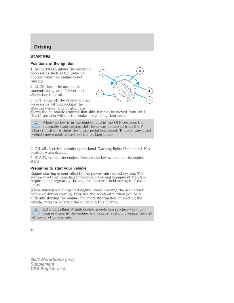
Positions of the ignition1. ACCESSORY, allows the electricalaccessories such as the radio tooperate while the engine is notrunning.
2. LOCK, locks the automatictransmission gearshift lever andallows key removal.
3. OFF, shuts off the engine and allaccessories without locking thesteering wheel. This position alsoallows the automatic transmission shift lever to be moved from the P(Park) position without the brake pedal being depressed.
When the key is in the ignition and in the OFF position, theautomatic transmission shift lever can be moved from the P
(Park) position without the brake pedal depressed. To avoid unwantedvehicle movement, always set the parking brake.
4. ON, all electrical circuits operational. Warning lights illuminated. Keyposition when driving.5. START, cranks the engine. Release the key as soon as the enginestarts.
Preparing to start your vehicleEngine starting is controlled by the powertrain control system. Thissystem meets all Canadian Interference-Causing Equipment standardrequirements regulating the impulse electrical field strength of radionoise.
When starting a fuel-injected engine, avoid pressing the acceleratorbefore or during starting. Only use the accelerator when you havedifficulty starting the engine. For more information on starting thevehicle, refer to Starting the engine in this chapter.
Extended idling at high engine speeds can produce very hightemperatures in the engine and exhaust system, creating the risk
of fire or other damage.
1
2 3
4
5
2004 Motorhome (mot)SupplementUSA English (fus)
Driving
Driving
20

Do not park, idle, or drive your vehicle in dry grass or other dryground cover. The emission system heats up the engine
compartment and exhaust system, which can start a fire.
Do not start your vehicle in a closed garage or in other enclosedareas. Exhaust fumes can be toxic. Always open the garage door
before you start the engine. See Guarding against exhaust fumes inthis chapter for more instructions.
If you smell exhaust fumes inside your vehicle, have your dealerinspect your vehicle immediately. Do not drive if you smell
exhaust fumes.
Important safety precautions
A computer system controls the engine’s idle revolutions per minute(RPM). When the engine starts, the idle RPM runs higher than normal inorder to warm the engine. If the engine idle speed does not slow downautomatically, have the vehicle checked. Do not allow the vehicle to idlefor more than 10 minutes.
Before starting the vehicle:
1. Make sure all vehicle occupants have buckled their safety belts.
2. Make sure the headlamps and vehicle accessories are off.
3. Make sure the parking brake isset.
2004 Motorhome (mot)SupplementUSA English (fus)
Driving
21
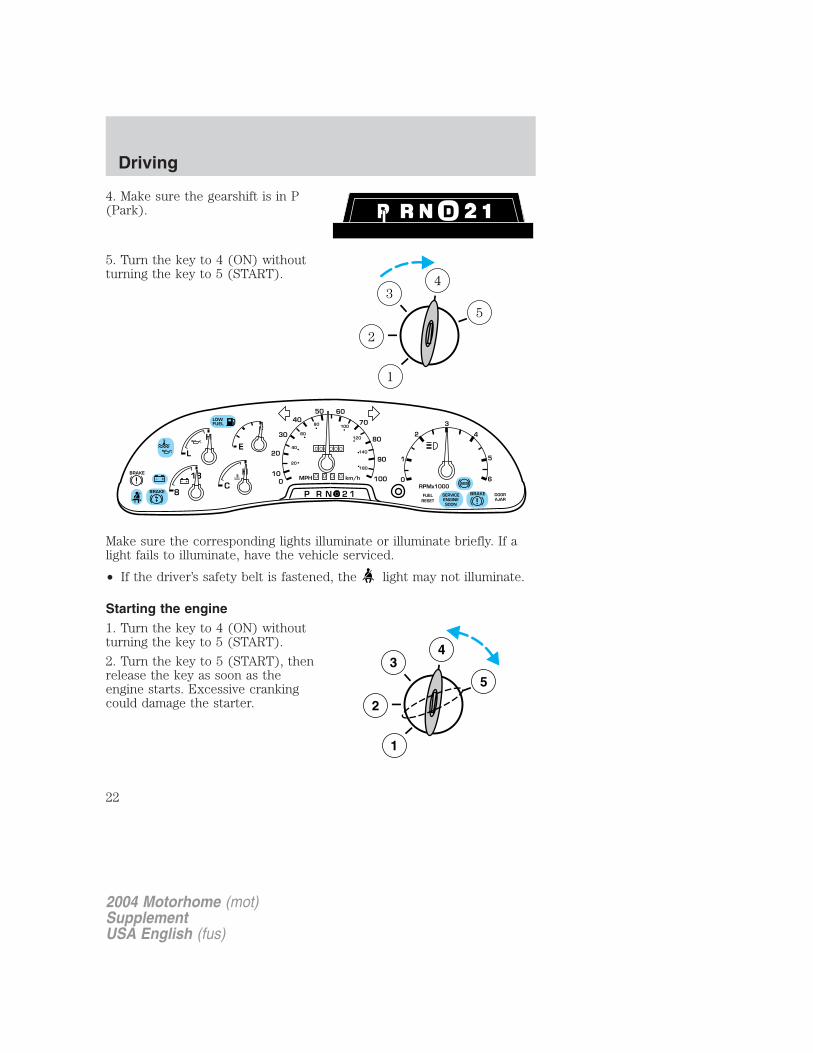
4. Make sure the gearshift is in P(Park).
5. Turn the key to 4 (ON) withoutturning the key to 5 (START).
Make sure the corresponding lights illuminate or illuminate briefly. If alight fails to illuminate, have the vehicle serviced.
• If the driver’s safety belt is fastened, the light may not illuminate.
Starting the engine1. Turn the key to 4 (ON) withoutturning the key to 5 (START).
2. Turn the key to 5 (START), thenrelease the key as soon as theengine starts. Excessive crankingcould damage the starter.
1
2
34
5
F
E
C
H
H
L
18
8 P R N 2 1
LOWFUEL
BRAKE
!
+ - + -0 0 0
0 0 0 0 0 0
0
50 60
70
20
100
30
40
80
90
100
20
40
60
80 100
120
140
180
MPH km/hBRAKE
!
1
0
2
RPMx1000
3
4
5
6
SERVICEENGINESOON
ABS
FUELRESET
DOORAJAR
BRAKE
3
2
1
5
4
2004 Motorhome (mot)SupplementUSA English (fus)
Driving
22
Note: If the engine does not start within five seconds on the first try,turn the key to 3 (OFF), wait 10 seconds and try again. If the engine stillfails to start, press the accelerator to the floor and try again; this willallow the engine to crank with the fuel shut off in case the engine isflooded with fuel.
Using the engine block heater (if equipped)Use of an engine block heater is strongly recommended if you live in aregion where temperatures reach -23° C (-10° F) or below. For bestresults, plug the heater in at least three hours before starting the vehicle.The heater can be plugged in the night before starting the vehicle.
To reduce the risk of electrical shock, do not use your heaterwith ungrounded electrical systems or two-pronged (cheater)
adapters.
Guarding against exhaust fumesCarbon monoxide is present in exhaust fumes. Take precautions to avoidits dangerous effects.
If you smell exhaust fumes inside your vehicle, have your dealerinspect your vehicle immediately. Do not drive if you smell
exhaust fumes.
Important ventilating informationIf the engine is idling while the vehicle is stopped in an open area forlong periods of time, open the windows at least 2.5 cm (one inch).
Adjust the heating or air conditioning (if equipped) to bring in fresh air.
Improve vehicle ventilation by keeping all air inlet vents clear of snow,leaves and other debris.
BRAKESYour service brakes are self-adjusting. Refer to the Scheduledmaintenance guide for scheduled maintenance.
Occasional brake noise is normal and often does not indicate aperformance concern with the vehicle’s brake system. In normaloperation, automotive brake systems may emit occasional or intermittentsqueal or groan noises when the brakes are applied. Such noises areusually heard during the first few brake applications in the morning;
2004 Motorhome (mot)SupplementUSA English (fus)
Driving
23
however, they may be heard at any time while braking and can beaggravated by environmental conditions such as cold, heat, moisture,road dust, salt or mud. If a “metal-to-metal,” “continuous grinding” or“continuous squeal” sound is present while braking, the brake liningsmay be worn-out and should be inspected by a qualified servicetechnician.
If you are driving down a long or steep hill, shift to a lower gear.Do not apply your brakes continuously, as they may overheat
and become less effective.
Anti-lock brake system (ABS)On vehicles equipped with an anti-lock braking system (ABS), a noisefrom the hydraulic pump motor and pulsation in the pedal may beobserved during ABS braking events. Pedal pulsation coupled with noisewhile braking under panic conditions or on loose gravel, bumps, wet orsnowy roads is normal and indicates proper functioning of the vehicle’santi-lock brake system. The ABS performs a self-check after you startthe engine and begin to drive away. A brief mechanical noise may beheard during this test. This is normal. If a malfunction is found, the ABSwarning light will come on. If the vehicle has continuous vibration orshudder in the steering wheel while braking, the vehicle should beinspected by a qualified service technician.
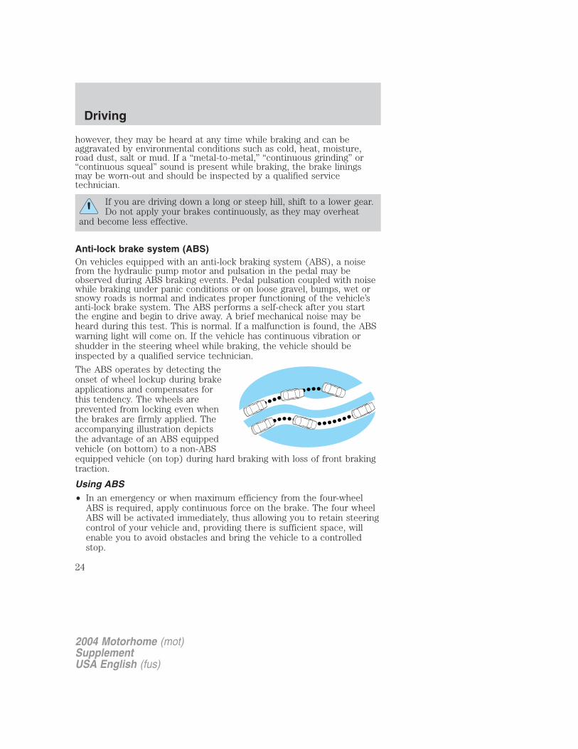
The ABS operates by detecting theonset of wheel lockup during brakeapplications and compensates forthis tendency. The wheels areprevented from locking even whenthe brakes are firmly applied. Theaccompanying illustration depictsthe advantage of an ABS equippedvehicle (on bottom) to a non-ABSequipped vehicle (on top) during hard braking with loss of front brakingtraction.
Using ABS• In an emergency or when maximum efficiency from the four-wheel
ABS is required, apply continuous force on the brake. The four wheelABS will be activated immediately, thus allowing you to retain steeringcontrol of your vehicle and, providing there is sufficient space, willenable you to avoid obstacles and bring the vehicle to a controlledstop.
2004 Motorhome (mot)SupplementUSA English (fus)
Driving
24
• The anti-lock system does not reduce stopping distance. Always leaveenough room between your vehicle and the vehicle in front of you tostop.
• We recommend that you familiarize yourself with this brakingtechnique. However, avoid taking any unnecessary risks.
Hydraulic brake booster system (Hydroboost or Hydromax)The Hydroboost and Hydromax systems receive fluid pressure from thepower steering pump to provide power assist during braking.
The Hydromax booster receives backup pressure from the reservesystem electric pump whenever the fluid in the power steering system isnot flowing. When the engine is OFF, the pump will turn on if the brakepedal is applied, or if the ignition is turned to the ON position.
The sound of the pump operating may be heard by the driver, but this isa normal characteristic of the system.
The reserve system provides reduced braking power, so the vehicleshould be operated under these conditions with caution, and only to seekservice repair and remove the vehicle from the roadway.
For Hydromax-equipped vehicles operating under normalconditions, the noise of the fluid flowing through the booster may beheard whenever the brake is applied. This condition is normal. Vehicleservice is not required.
If braking performance or pedal response becomes very poor, even whenthe pedal is strongly depressed, it may indicate the presence of air in thehydraulic system or leakage of fluid. Stop the vehicle safely as soon aspossible and seek service immediately.
ABS warning lamp
The ABS warning lamp in the instrument cluster momentarily illuminateswhen the ignition is turned to the ON position. If the light remains onafter the vehicle is started, continues to flash or fails to illuminate, havethe system serviced immediately. With the ABS light on, the anti-lockbrake system is disabled and normal braking is still effective unless thebrake warning light also remains illuminated.
With the ABS light on, the anti-lockbrake system is disabled and normalbraking is still effective unless thebrake warning light also remainsilluminated with parking brake released. (If your brake warning lampilluminates, have your vehicle serviced immediately.)
2004 Motorhome (mot)SupplementUSA English (fus)
Driving
25
Parking brake
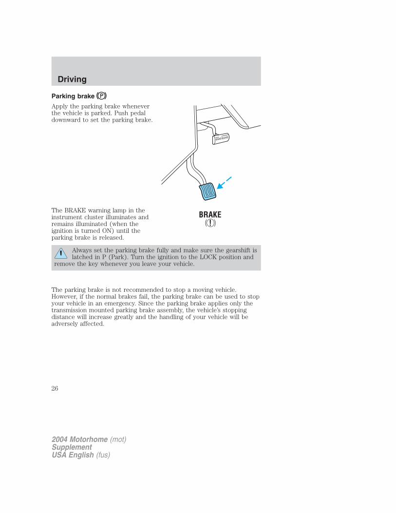
Apply the parking brake wheneverthe vehicle is parked. Push pedaldownward to set the parking brake.
The BRAKE warning lamp in theinstrument cluster illuminates andremains illuminated (when theignition is turned ON) until theparking brake is released.
Always set the parking brake fully and make sure the gearshift islatched in P (Park). Turn the ignition to the LOCK position and
remove the key whenever you leave your vehicle.
The parking brake is not recommended to stop a moving vehicle.However, if the normal brakes fail, the parking brake can be used to stopyour vehicle in an emergency. Since the parking brake applies only thetransmission mounted parking brake assembly, the vehicle’s stoppingdistance will increase greatly and the handling of your vehicle will beadversely affected.
2004 Motorhome (mot)SupplementUSA English (fus)
Driving
26
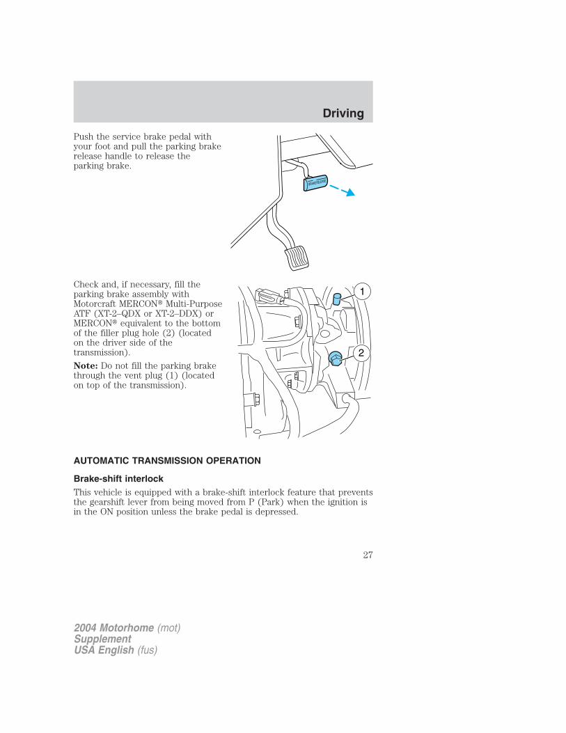
Push the service brake pedal withyour foot and pull the parking brakerelease handle to release theparking brake.
Check and, if necessary, fill theparking brake assembly withMotorcraft MERCON� Multi-PurposeATF (XT-2–QDX or XT-2–DDX) orMERCON� equivalent to the bottomof the filler plug hole (2) (locatedon the driver side of thetransmission).
Note: Do not fill the parking brakethrough the vent plug (1) (locatedon top of the transmission).
AUTOMATIC TRANSMISSION OPERATION
Brake-shift interlockThis vehicle is equipped with a brake-shift interlock feature that preventsthe gearshift lever from being moved from P (Park) when the ignition isin the ON position unless the brake pedal is depressed.
2004 Motorhome (mot)SupplementUSA English (fus)
Driving
27

If you cannot move the gearshift lever out of P (Park) with ignition inthe ON position and the brake pedal depressed:
1. Apply the parking brake, turn ignition key to LOCK, then remove thekey.
2. Insert the key and turn it to OFF. Apply the brake pedal and shiftto N (Neutral).
When the key is in the ignition and in the OFF position, theautomatic transmission shift lever can be moved from the P
(Park) position without the brake pedal depressed. To avoid unwantedvehicle movement, always set the parking brake.
3. Start the vehicle.
If it is necessary to use the above procedure to move the gearshift lever,it is possible that a fuse has blown or the vehicle’s brakelamps are notoperating properly. Refer to Fuses and relays in the Roadsideemergencies chapter.
Do not drive your vehicle until you verify that the brakelampsare working.
Always set the parking brake fully and make sure the gearshift islatched in P (Park). Turn the ignition to the LOCK position and
remove the key whenever you leave your vehicle.
If the parking brake is fully released, but the brake warning lampremains illuminated, the brakes may not be working properly.
See your dealer or a qualified service technician.
Understanding the gearshift positions of the 4–speed automatictransmission
2004 Motorhome (mot)SupplementUSA English (fus)
Driving
28
P (Park)
This position locks the transmission and prevents the rear wheels fromturning.To put your vehicle in gear:• Start the engine• Depress the brake pedal• Move the gearshift lever into the desired gearTo put your vehicle in P (Park):• Come to a complete stop
• Move the gearshift lever and securely latch it in P (Park)
Always set the parking brake fully and make sure the gearshift islatched in P (Park). Turn the ignition to the LOCK position and
remove the key whenever you leave your vehicle.
R (Reverse)
With the gearshift lever in R (Reverse), the vehicle will move backward.Always come to a complete stop before shifting into and out of R(Reverse).
N (Neutral)
With the gearshift lever in N (Neutral), the vehicle can be started and isfree to roll. Hold the brake pedal down while in this position.
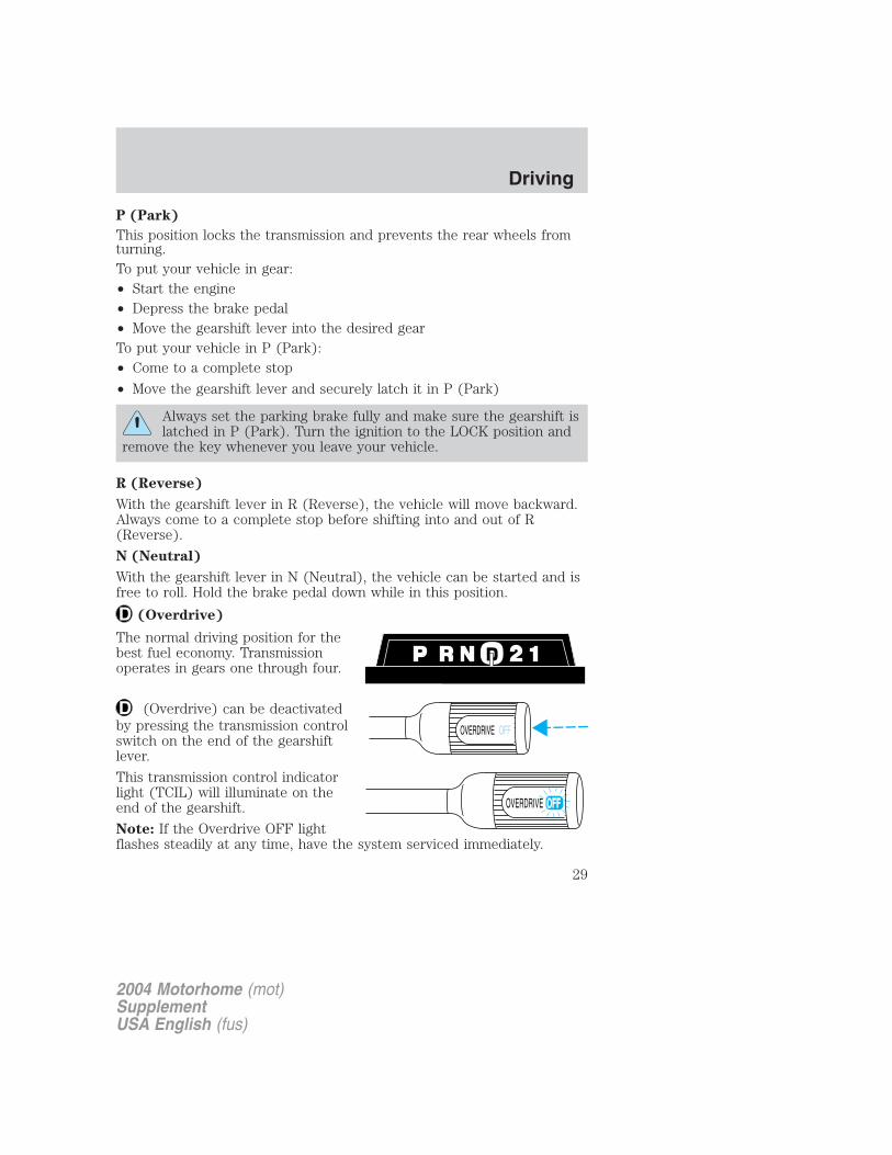
(Overdrive)
The normal driving position for thebest fuel economy. Transmissionoperates in gears one through four.
(Overdrive) can be deactivatedby pressing the transmission controlswitch on the end of the gearshiftlever.
This transmission control indicatorlight (TCIL) will illuminate on theend of the gearshift.
Note: If the Overdrive OFF lightflashes steadily at any time, have the system serviced immediately.
OVERDRIVE OFF
OVERDRIVE
2004 Motorhome (mot)SupplementUSA English (fus)
Driving
29
Drive (not shown)
Drive is activated when the transmission control switch is pressed.
• This position allows for all forward gears except overdrive.
• O/D OFF lamp is illuminated.
• Provides engine braking.
• Use when driving conditions cause excessive shifting from O/D toother gears. Examples: city traffic, hilly terrain, heavy loads, trailertowing and when engine braking is required.
• To return to O/D (overdrive mode), press the transmission controlswitch. The O/D OFF lamp will not be illuminated.
• O/D (Overdrive) is automatically returned each time the key is turnedoff regardless of last mode of operation.
2 (Second)
This position allows for second gear only.
• Provides engine braking.
• Use to start-up on slippery roads.
• To return to (Overdrive), move the gearshift lever into the(Overdrive) position.
• Selecting 2 (Second) at higher speeds will cause the transmission todownshift to second gear at the appropriate vehicle speed.
1 (First)
• Provides maximum engine braking.
• Allows upshifts by moving gearshift lever.
• Will not downshift into 1 (First) at high speeds; allows for 1 (First)when vehicle reaches slower speeds.
Forced downshifts
• Allowed in (Overdrive) or Drive.
• Depress the accelerator to the floor.
• Allows transmission to select an appropriate gear.
2004 Motorhome (mot)SupplementUSA English (fus)
Driving
30
If your vehicle gets stuck in mud or snowIf your vehicle gets stuck in mud or snow, it may be rocked out byshifting from forward and reverse gears, stopping between shifts in asteady pattern. Press lightly on the accelerator in each gear.Do not rock the vehicle if the engine is not at normal operatingtemperature or damage to the transmission may occur.
Do not rock the vehicle for more than a minute or damage to thetransmission and tires may occur, or the engine may overheat.
DRIVING THROUGH WATERDo not drive quickly through standing water, especially if the depth isunknown. Traction or brake capability may be limited and if the ignitionsystem gets wet, your engine may stall. Water may also enter yourengine’s air intake and severely damage your engine.
If driving through deep or standing water is unavoidable, proceed veryslowly. Never drive through water that is higher than the bottom of thehubs (for trucks) or the bottom of the wheel rims (for cars).
Once through the water, always try the brakes. Wet brakes do not stopthe vehicle as effectively as dry brakes. Drying can be improved bymoving your vehicle slowly while applying light pressure on the brakepedal.
Driving through deep water where the transmission vent tube issubmerged may allow water into the transmission and causeinternal transmission damage. Have the fluid checked and, ifwater is found, replace the fluid.
VEHICLE LOADINGYour vehicle’s load capacity is designed by weight, not volume, so youcannot necessarily use all available space with large or heavy loads.Maximum safe vehicle weights as well as tire, rim sizes and inflationpressures are specified for your vehicle on the Safety ComplianceCertification Label. A Certification Label was supplied by Ford MotorCompany to the Motorhome Manufacturer. The manufacturer uses thisinformation and supplies a Certification Label which is located inside thevehicle to the left of the driver.
Before loading a vehicle, familiarize yourself with the following terms:
• Base Curb Weight: Weight of the vehicle including any standardequipment, fluids, lubricants, etc. It does not include occupants oraftermarket equipment.
2004 Motorhome (mot)SupplementUSA English (fus)
Driving
31
• Payload: Combined maximum allowable weight of cargo, occupantsand optional equipment. The payload equals the gross vehicle weightrating minus base curb weight.
• GVW (Gross Vehicle Weight): Base curb weight plus payloadweight. The GVW is not a limit or a specification.
• GVWR (Gross Vehicle Weight Rating): Maximum permissible totalweight of the base vehicle, occupants, optional equipment and cargo.The GVWR is specific to each vehicle and is listed on the CertificationLabel, located near the driver’s seat or on the driver’s door pillar.
• GAWR (Gross Axle Weight Rating): Carrying capacity for each axlesystem. The GAWR is specific to each vehicle and is listed on theCertification Label, located near the driver’s seat or on the driver’sdoor pillar.
• GCWR (Gross Combined Weight Rating): Maximum permissiblecombined weight of towing vehicle (including occupants and cargo)and the loaded trailer.
• Maximum Trailer Weight Rating: Maximum weight of a trailer theloaded vehicle (including occupants and cargo) is permitted to tow.The maximum trailer weight rating is determined by subtracting thevehicle curb weight for each engine/transmission combination, anyrequired option weight for trailer towing and the weight of the driverfrom the GCWR for the towing vehicle.
• Trailer Weight Range: Specified weight range that the trailer mustfall within that ranges from zero to the maximum trailer weight rating.
Remember to figure in the tongue load of your loaded trailer whenfiguring the total weight.
Exceeding any vehicle weight rating limitation could result inserious damage to the vehicle loss of vehicle control, vehicle
rollover, and/or personal injury.
Do not use replacement tires with lower weight capacities than theoriginals because they may lower the vehicle’s GVWR and GAWRlimitations. Replacement tires with a higher weight limit than theoriginals do not increase the GVWR and GAWR limitations.
2004 Motorhome (mot)SupplementUSA English (fus)
Driving
32

Calculating the load your vehicle can carry/tow1. Use the appropriate maximum gross combined weight rating (GCWR)chart to find the maximum GCWR for your type engine and rear axle ratio.
2. Weigh your vehicle as you customarily operate the vehicle withoutcargo. To obtain correct weights, try taking your vehicle to a shippingcompany or an inspection station for trucks.
3. Subtract your loaded vehicle weight from the maximum GCWR on thefollowing charts. This is the maximum combined cargo and trailer weightyour vehicle can carry/tow and must fall below the maximum shownunder maximum trailer weight on the chart. Refer to the definition ofMaximum Trailer Weight below Vehicle Loading in this chapter todetermine the maximum trailer weight permitted for a loaded vehicle.
Vehicle Loading – with and without a trailerThis section will guide you in the proper loading of your vehicle and/ortrailer, to keep your loaded vehicle weight within its design ratingcapability, with or without a trailer. Properly loading your vehicle willprovide maximum return of vehicle design performance. Before loadingyour vehicle, familiarize yourself with the following terms for determiningyour vehicle’s weight ratings, with or without a trailer, from the vehicle’sSafety Certification Label and Tire and Load Information Label:
Base Curb Weight – is the weight of the vehicle including a full tank offuel and all standard equipment. It does not include passengers, cargo, oroptional equipment.
Vehicle Curb Weight – is the weight of your new vehicle when youpicked it up from your dealer plus any aftermarket equipment.
Cargo Weight – includes all weight added to the Base Curb Weight,including cargo and optional equipment. When towing, trailer tongue loador king pin weight is also part of cargo weight.
GAW (Gross Axle Weight) – is the total weight placed on each axle(front and rear) – including vehicle curb weight and all payload.
2004 Motorhome (mot)SupplementUSA English (fus)
Driving
33

GAWR (Gross Axle Weight Rating) – is the maximum allowableweight that can be carried by a single axle (front or rear). Thesenumbers are shown on the Safety Compliance Certification Labellocated on the driver’s door or door pillar. The total load on eachaxle must never exceed its GAWR.
Exceeding the Safety Certification Label axle weight rating limitscould result in substandard vehicle handling, performance,
engine, transmission and/or structural damage, serious damage to thevehicle, loss of control and personal injury.
Note: For trailer towing information refer to Trailer Towing found inthis chapter or the RV and Trailer Towing Guide provided by yourdealership.
GVW (Gross Vehicle Weight) – is the Vehicle Curb Weight + cargo +passengers.
GVWR (Gross Vehicle WeightRating) – is the maximumallowable weight of the fully loadedvehicle (including all options,equipment, passengers and cargo).The GVWR is shown on theSafety Compliance CertificationLabel located on the driver’sdoor or door pillar. The GVWmust never exceed the GVWR.
2004 Motorhome (mot)SupplementUSA English (fus)
Driving
34
Exceeding the Safety Certification Label axle weight rating limitscould result in substandard vehicle handling, performance,
engine, transmission and/or structural damage, serious damage to thevehicle, loss of control and personal injury.
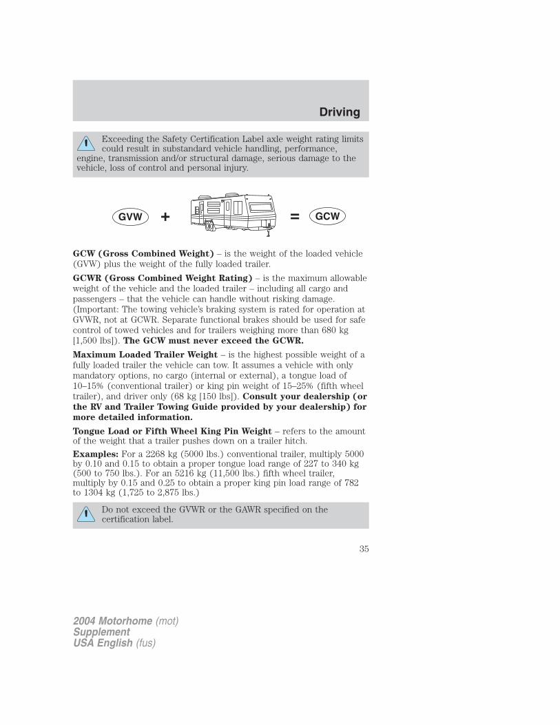
GCW (Gross Combined Weight) – is the weight of the loaded vehicle(GVW) plus the weight of the fully loaded trailer.
GCWR (Gross Combined Weight Rating) – is the maximum allowableweight of the vehicle and the loaded trailer – including all cargo andpassengers – that the vehicle can handle without risking damage.(Important: The towing vehicle’s braking system is rated for operation atGVWR, not at GCWR. Separate functional brakes should be used for safecontrol of towed vehicles and for trailers weighing more than 680 kg[1,500 lbs]). The GCW must never exceed the GCWR.
Maximum Loaded Trailer Weight – is the highest possible weight of afully loaded trailer the vehicle can tow. It assumes a vehicle with onlymandatory options, no cargo (internal or external), a tongue load of10–15% (conventional trailer) or king pin weight of 15–25% (fifth wheeltrailer), and driver only (68 kg [150 lbs]). Consult your dealership (or
the RV and Trailer Towing Guide provided by your dealership) for
more detailed information.
Tongue Load or Fifth Wheel King Pin Weight – refers to the amountof the weight that a trailer pushes down on a trailer hitch.
Examples: For a 2268 kg (5000 lbs.) conventional trailer, multiply 5000by 0.10 and 0.15 to obtain a proper tongue load range of 227 to 340 kg(500 to 750 lbs.). For an 5216 kg (11,500 lbs.) fifth wheel trailer,multiply by 0.15 and 0.25 to obtain a proper king pin load range of 782to 1304 kg (1,725 to 2,875 lbs.)
Do not exceed the GVWR or the GAWR specified on thecertification label.
2004 Motorhome (mot)SupplementUSA English (fus)
Driving
35
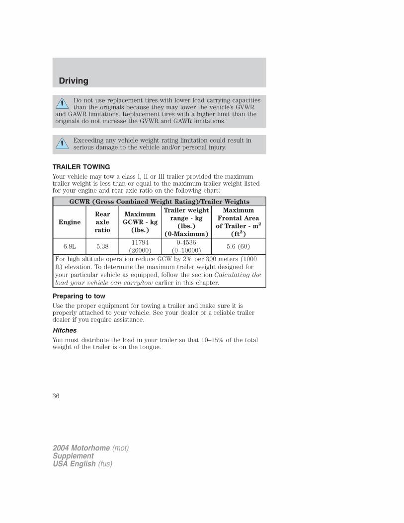
Do not use replacement tires with lower load carrying capacitiesthan the originals because they may lower the vehicle’s GVWR
and GAWR limitations. Replacement tires with a higher limit than theoriginals do not increase the GVWR and GAWR limitations.
Exceeding any vehicle weight rating limitation could result inserious damage to the vehicle and/or personal injury.
TRAILER TOWINGYour vehicle may tow a class I, II or III trailer provided the maximumtrailer weight is less than or equal to the maximum trailer weight listedfor your engine and rear axle ratio on the following chart:
GCWR (Gross Combined Weight Rating)/Trailer Weights
Engine
Rear
axle
ratio
Maximum
GCWR - kg
(lbs.)
Trailer weight
range - kg
(lbs.)
(0-Maximum)
Maximum
Frontal Area
of Trailer - m2
(ft2)
6.8L 5.3811794
(26000)0-4536
(0–10000)5.6 (60)
For high altitude operation reduce GCW by 2% per 300 meters (1000ft) elevation. To determine the maximum trailer weight designed foryour particular vehicle as equipped, follow the section Calculating the
load your vehicle can carry/tow earlier in this chapter.
Preparing to towUse the proper equipment for towing a trailer and make sure it isproperly attached to your vehicle. See your dealer or a reliable trailerdealer if you require assistance.
HitchesYou must distribute the load in your trailer so that 10–15% of the totalweight of the trailer is on the tongue.
2004 Motorhome (mot)SupplementUSA English (fus)
Driving
36
Load equalizing hitchWhen hooking up a trailer using a load equalizing hitch, always use thefollowing procedure:
1. Park the unloaded vehicle on a level surface. With the ignition on andall doors closed, allow the vehicle to stand for several minutes so that itcan level.
2. Measure the height of a reference point on the front and rear bumpersat the center of the vehicle.
3. Attach the trailer to the vehicle and adjust the hitch equalizers so thatthe front bumper height is within 0–13 mm (0.5 in) of the referencepoint. After proper adjustment, the rear bumper should be no higherthan in Step 2.
Note: Adjusting an equalizing hitch so the rear bumper of the vehicle ishigher than it was unloaded will defeat the function of the loadequalizing hitch and may cause unpredictable handling.
Safety chainsAlways connect the trailer’s safety chains to the frame or hook retainersof the vehicle hitch. To connect the trailer’s safety chains, cross thechains under the trailer tongue and allow slack for turning corners.
If you use a rental trailer, follow the instructions that the rental agencygives to you.
Do not attach safety chains to the bumper.
Trailer brakesElectric brakes and manual, automatic or surge-type brakes are safe ifinstalled properly and adjusted to the manufacturer’s specifications. Thetrailer brakes must meet local and Federal regulations.
Do not connect a trailer’s hydraulic brake system directly to yourvehicle’s brake system. Your vehicle may not have enough
braking power and your chances of having a collision greatly increase.
The towing vehicle braking system is rated for operation at theGVWR, not the GCWR.
Separate functioning brake systems are required for safe controlof towed vehicles and trailers weighing more than 680 kg (1 500lbs) when loaded.
2004 Motorhome (mot)SupplementUSA English (fus)
Driving
37
Trailer lamps
Trailer lamps are required on most towed vehicles. Make sure all runninglights, brake lights, turn signals and hazard lights are working. See yourdealer or trailer rental agency for proper instructions and equipment forhooking up trailer lamps.
Driving while you tow
When towing a trailer:
• Turn off the speed control. The speed control may shut offautomatically when you are towing on long, steep grades.
• Consult your local motor vehicle speed regulations for towing a trailer.
• To eliminate excessive shifting, use a lower gear. This will also assistin transmission cooling.
• Anticipate stops and brake gradually.
Servicing after towing
If you tow a trailer for long distances, your vehicle will require morefrequent service intervals. Refer to your scheduled maintenance guide formore information.
Trailer towing tips• Practice turning, stopping and backing up before starting on a trip to
get the feel of the vehicle trailer combination. When turning, makewider turns so the trailer wheels will clear curbs and other obstacles.
• Allow more distance for stopping with a trailer attached.
• If you are driving down a long or steep hill, shift to a lower gear. Donot apply the brakes continuously, as they may overheat and becomeless effective.
• The trailer tongue weight should be 10–15% of the loaded trailerweight.
• After you have traveled 80 km (50 miles), thoroughly check yourhitch, electrical connections and trailer wheel lug nuts.
• To aid in engine/transmission cooling and A/C efficiency during hotweather while stopped in traffic, place the gearshift lever in P (Park).
• Vehicles with trailers should not be parked on a grade. If you mustpark on a grade, place wheel chocks under the trailer’s wheels.
2004 Motorhome (mot)SupplementUSA English (fus)
Driving
38
GETTING ROADSIDE ASSISTANCETo fully assist you should you have a vehicle concern, Ford MotorCompany offers a complimentary roadside assistance program. Thisprogram is separate from the New Vehicle Limited Warranty. The serviceis available:
• 24–hours, seven days a week
• for the New Vehicle Limited Warranty period of three years or 60,000km (36,000 miles), whichever occurs first on Ford and Mercuryvehicles, and four years or 80,000 km (50,000 miles) on Lincolnvehicles.
Roadside assistance will cover:
• changing a flat tire
• jump-starts
• lock-out assistance
• limited fuel delivery
• towing of your disabled vehicle to the nearest Ford Motor Companydealership, or your selling dealer if within 56.3 km (35 miles) of thenearest Ford Motor Company dealership (one tow per disablement).Even non-warranty related tows, like accidents or getting stuck in themud or snow, are covered (some exclusions apply, such as impoundtowing or repossession).
Canadian customers refer to your Owner Information Guide forinformation on:
• coverage period
• exact fuel amounts
• towing of your disabled vehicle
• emergency travel expense reimbursement
• travel planning benefits
USING ROADSIDE ASSISTANCECustomers in the U.S. and Canada who require roadside assistance, maycontact 1–800–444–3311.
2004 Motorhome (mot)SupplementUSA English (fus)
Roadside emergencies
Roadside emergencies
39
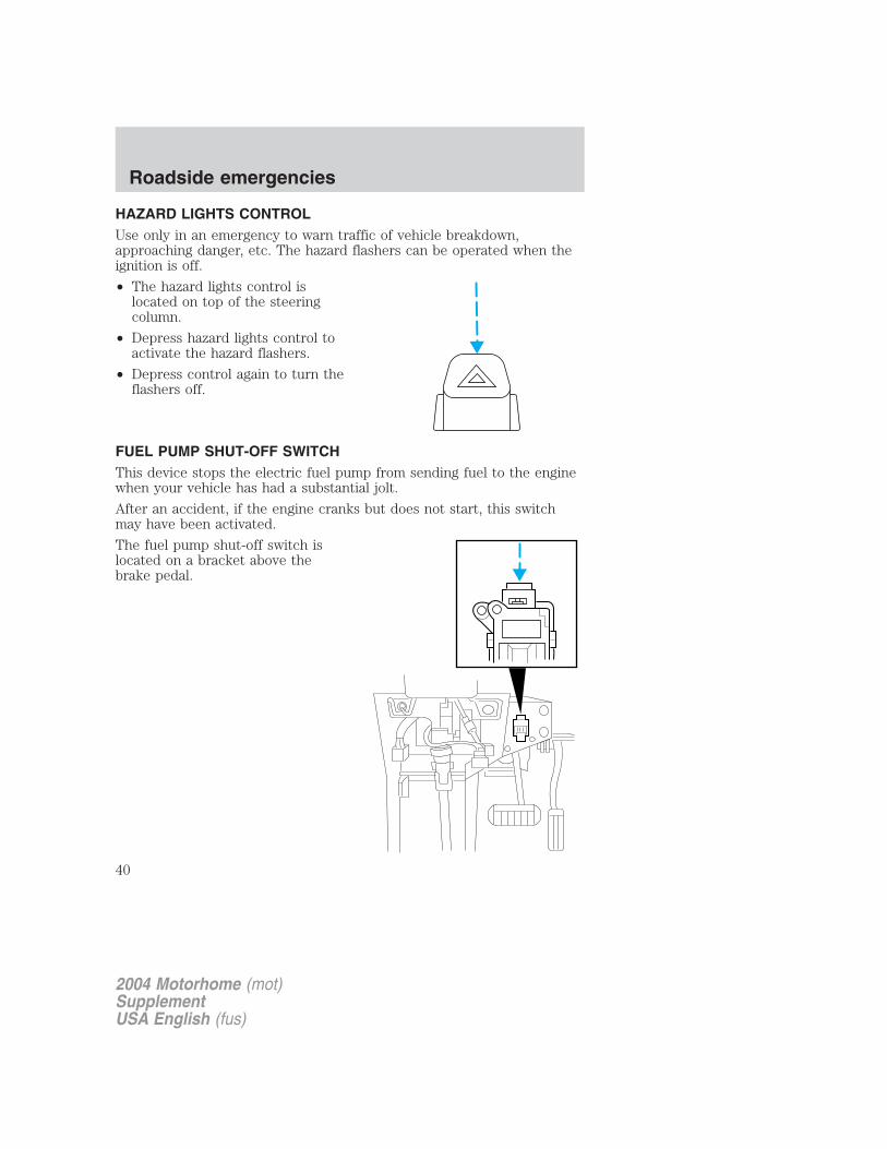
HAZARD LIGHTS CONTROLUse only in an emergency to warn traffic of vehicle breakdown,approaching danger, etc. The hazard flashers can be operated when theignition is off.
• The hazard lights control islocated on top of the steeringcolumn.
• Depress hazard lights control toactivate the hazard flashers.
• Depress control again to turn theflashers off.
FUEL PUMP SHUT-OFF SWITCHThis device stops the electric fuel pump from sending fuel to the enginewhen your vehicle has had a substantial jolt.
After an accident, if the engine cranks but does not start, this switchmay have been activated.
The fuel pump shut-off switch islocated on a bracket above thebrake pedal.
2004 Motorhome (mot)SupplementUSA English (fus)
Roadside emergencies
40
Use the following procedure to reset the fuel pump shut-off switch.
1. Turn the ignition to the OFF position.
2. Check the fuel system for leaks.
3. If no fuel leak is apparent, reset the fuel pump shut-off switch bypushing in on the reset button.
4. Turn the ignition to the ON position. Pause for a few seconds andreturn the key to the OFF position.
5. Make a further check for leaks in the fuel system.
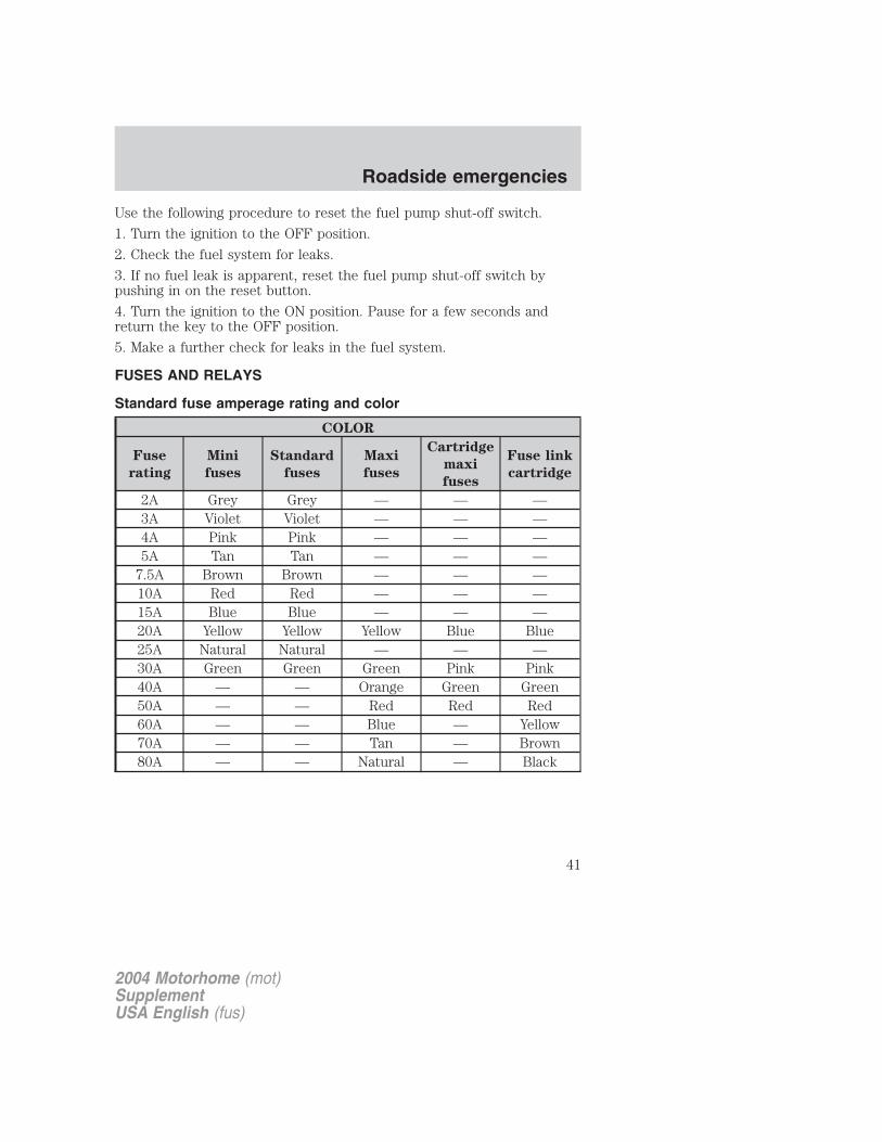
FUSES AND RELAYS
Standard fuse amperage rating and color
COLOR
Fuse
rating
Mini
fuses
Standard
fuses
Maxi
fuses
Cartridge
maxi
fuses
Fuse link
cartridge
2A Grey Grey — — —3A Violet Violet — — —4A Pink Pink — — —5A Tan Tan — — —
7.5A Brown Brown — — —10A Red Red — — —15A Blue Blue — — —20A Yellow Yellow Yellow Blue Blue25A Natural Natural — — —30A Green Green Green Pink Pink40A — — Orange Green Green50A — — Red Red Red60A — — Blue — Yellow70A — — Tan — Brown80A — — Natural — Black
2004 Motorhome (mot)SupplementUSA English (fus)
Roadside emergencies
41
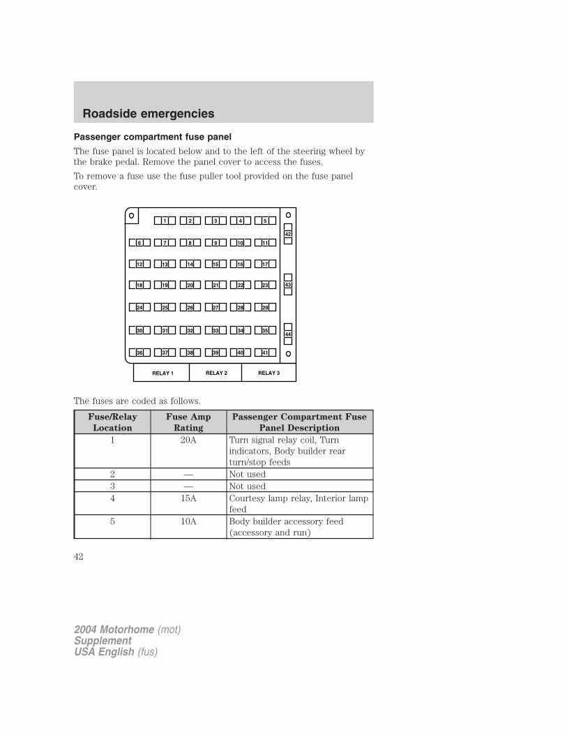
Passenger compartment fuse panel
The fuse panel is located below and to the left of the steering wheel bythe brake pedal. Remove the panel cover to access the fuses.
To remove a fuse use the fuse puller tool provided on the fuse panelcover.
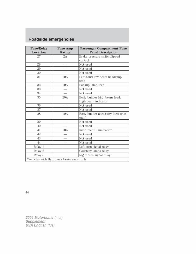
The fuses are coded as follows.
Fuse/Relay
Location
Fuse Amp
Rating
Passenger Compartment Fuse
Panel Description
1 20A Turn signal relay coil, Turnindicators, Body builder rearturn/stop feeds
2 — Not used3 — Not used4 15A Courtesy lamp relay, Interior lamp
feed5 10A Body builder accessory feed
(accessory and run)
2004 Motorhome (mot)SupplementUSA English (fus)
Roadside emergencies
42
Fuse/Relay
Location
Fuse Amp
Rating
Passenger Compartment Fuse
Panel Description
6 10A Trailer tow left stop/turn feed7 15A Blower motor relay coil8 — Not used9 20A Stoplamps: Trailer tow Electric
Brake controller feed, Bodybuilder rear turn/stop feeds, Bodybuilder stop lamp feed, Trailerturn/stop fuse feeds
10 5A Instrument cluster memory,Power brake assist lamp*
11 30A Wiper/Washer module, Wiper feed12 10A Trailer tow stop/turn feed13 10A ABS module14 10A Warning chime module, Power
brake assist module*, Instrumentcluster power, Instrument clusterwarning lamps, Transmissioncontrol switch
15 15A Left turn signal feed16 20A Body builder battery (+12V) feed17 5A Body builder radio feed18 — Not used19 5A DRL relays20 — Not used21 15A Right turn signal feed22 — Not used23 — Not used24 — Not used25 10A Right-hand low beam headlamp
feed26 10A Speed control module, Brake shift
interlock actuator
2004 Motorhome (mot)SupplementUSA English (fus)
Roadside emergencies
43
Fuse/Relay
Location
Fuse Amp
Rating
Passenger Compartment Fuse
Panel Description
27 2A Brake pressure switch/Speedcontrol
28 — Not used29 — Not used30 — Not used31 10A Left-hand low beam headlamp
feed32 10A Backup lamp feed33 — Not used34 — Not used35 20A Body builder high beam feed,
High beam indicator36 — Not used37 — Not used38 10A Body builder accessory feed (run
only)39 — Not used40 — Not used41 10A Instrument illumination42 — Not used43 — Not used44 — Not used
Relay 1 — Left turn signal relayRelay 2 —— Courtesy lamps relayRelay 3 Right turn signal relay
*Vehicles with Hydromax brake assist only
2004 Motorhome (mot)SupplementUSA English (fus)
Roadside emergencies
44
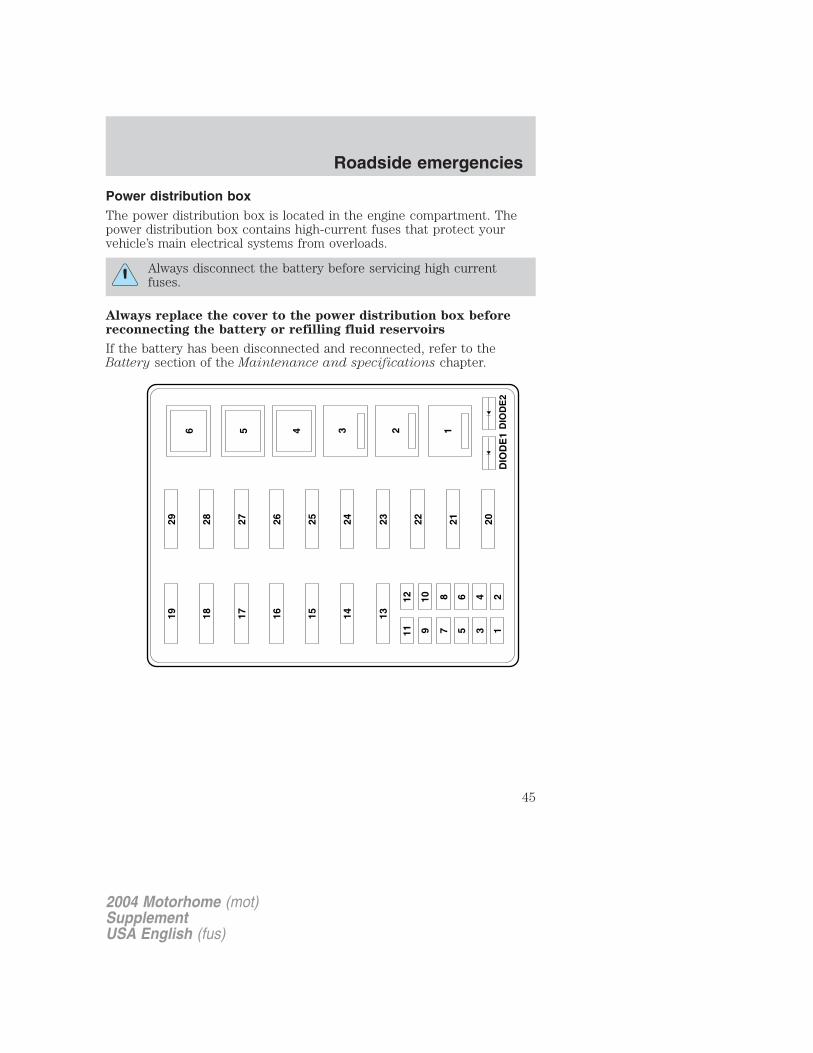
Power distribution boxThe power distribution box is located in the engine compartment. Thepower distribution box contains high-current fuses that protect yourvehicle’s main electrical systems from overloads.
Always disconnect the battery before servicing high currentfuses.
Always replace the cover to the power distribution box beforereconnecting the battery or refilling fluid reservoirs
If the battery has been disconnected and reconnected, refer to theBattery section of the Maintenance and specifications chapter.
1929
1828
1727
1626
1525
1424
13
1112
910
78
56
34
12
23 22 21 20
6 5 4 3 2 1 DIO
DE
2D
IOD
E1
2004 Motorhome (mot)SupplementUSA English (fus)
Roadside emergencies
45
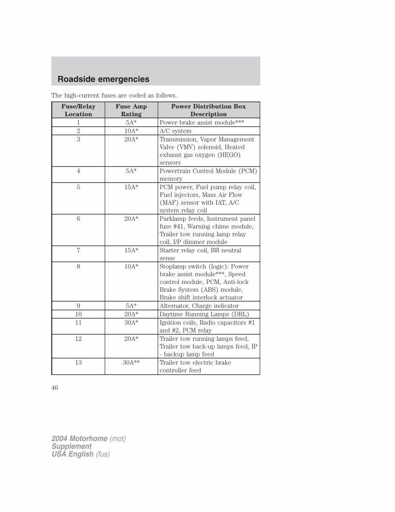
The high-current fuses are coded as follows.
Fuse/Relay
Location
Fuse Amp
Rating
Power Distribution Box
Description
1 5A* Power brake assist module***2 10A* A/C system3 20A* Transmission, Vapor Management
Valve (VMV) solenoid, Heatedexhaust gas oxygen (HEGO)sensors
4 5A* Powertrain Control Module (PCM)memory
5 15A* PCM power, Fuel pump relay coil,Fuel injectors, Mass Air Flow(MAF) sensor with IAT, A/Csystem relay coil
6 20A* Parklamp feeds, Instrument panelfuse #41, Warning chime module,Trailer tow running lamp relaycoil, I/P dimmer module
7 15A* Starter relay coil, BB neutralsense
8 10A* Stoplamp switch (logic): Powerbrake assist module***, Speedcontrol module, PCM, Anti-lockBrake System (ABS) module,Brake shift interlock actuator
9 5A* Alternator, Charge indicator10 20A* Daytime Running Lamps (DRL)11 30A* Ignition coils, Radio capacitors #1
and #2, PCM relay12 20A* Trailer tow running lamps feed,
Trailer tow back-up lamps feed, IP- backup lamp feed
13 30A** Trailer tow electric brakecontroller feed
2004 Motorhome (mot)SupplementUSA English (fus)
Roadside emergencies
46
Fuse/Relay
Location
Fuse Amp
Rating
Power Distribution Box
Description
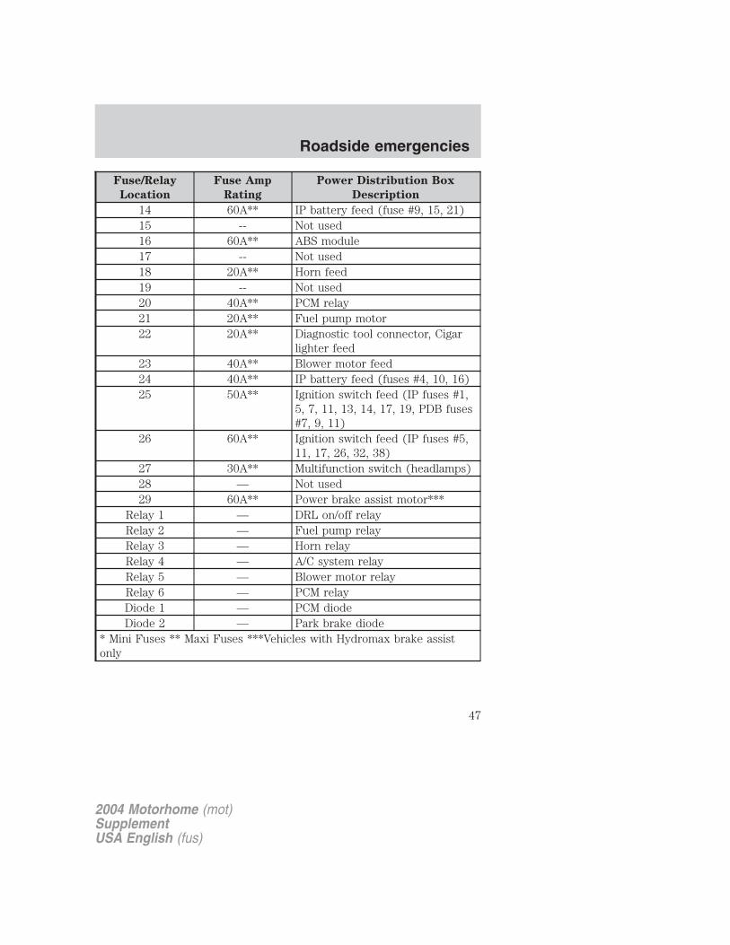
14 60A** IP battery feed (fuse #9, 15, 21)15 -- Not used16 60A** ABS module17 -- Not used18 20A** Horn feed19 -- Not used20 40A** PCM relay21 20A** Fuel pump motor22 20A** Diagnostic tool connector, Cigar
lighter feed23 40A** Blower motor feed24 40A** IP battery feed (fuses #4, 10, 16)25 50A** Ignition switch feed (IP fuses #1,
5, 7, 11, 13, 14, 17, 19, PDB fuses#7, 9, 11)
26 60A** Ignition switch feed (IP fuses #5,11, 17, 26, 32, 38)
27 30A** Multifunction switch (headlamps)28 — Not used29 60A** Power brake assist motor***
Relay 1 — DRL on/off relayRelay 2 — Fuel pump relayRelay 3 — Horn relayRelay 4 — A/C system relayRelay 5 — Blower motor relayRelay 6 — PCM relayDiode 1 — PCM diodeDiode 2 — Park brake diode
* Mini Fuses ** Maxi Fuses ***Vehicles with Hydromax brake assistonly
2004 Motorhome (mot)SupplementUSA English (fus)
Roadside emergencies
47
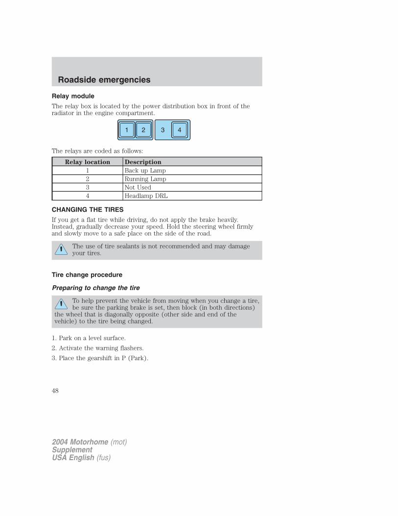
Relay module
The relay box is located by the power distribution box in front of theradiator in the engine compartment.
The relays are coded as follows:
Relay location Description
1 Back up Lamp2 Running Lamp3 Not Used4 Headlamp DRL
CHANGING THE TIRES
If you get a flat tire while driving, do not apply the brake heavily.Instead, gradually decrease your speed. Hold the steering wheel firmlyand slowly move to a safe place on the side of the road.
The use of tire sealants is not recommended and may damageyour tires.
Tire change procedure
Preparing to change the tire
To help prevent the vehicle from moving when you change a tire,be sure the parking brake is set, then block (in both directions)
the wheel that is diagonally opposite (other side and end of thevehicle) to the tire being changed.
1. Park on a level surface.
2. Activate the warning flashers.
3. Place the gearshift in P (Park).
1 2 43
2004 Motorhome (mot)SupplementUSA English (fus)
Roadside emergencies
48
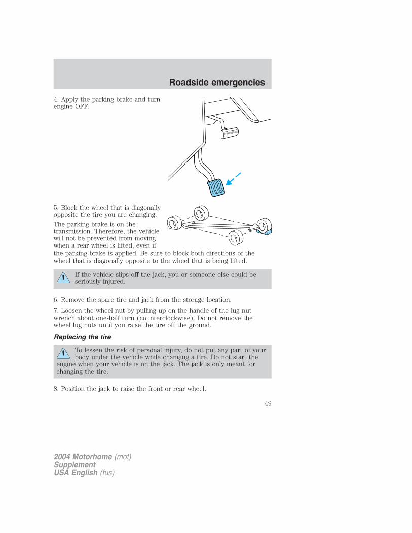
4. Apply the parking brake and turnengine OFF.
5. Block the wheel that is diagonallyopposite the tire you are changing.
The parking brake is on thetransmission. Therefore, the vehiclewill not be prevented from movingwhen a rear wheel is lifted, even ifthe parking brake is applied. Be sure to block both directions of thewheel that is diagonally opposite to the wheel that is being lifted.
If the vehicle slips off the jack, you or someone else could beseriously injured.
6. Remove the spare tire and jack from the storage location.
7. Loosen the wheel nut by pulling up on the handle of the lug nutwrench about one-half turn (counterclockwise). Do not remove thewheel lug nuts until you raise the tire off the ground.
Replacing the tire
To lessen the risk of personal injury, do not put any part of yourbody under the vehicle while changing a tire. Do not start the
engine when your vehicle is on the jack. The jack is only meant forchanging the tire.
8. Position the jack to raise the front or rear wheel.
2004 Motorhome (mot)SupplementUSA English (fus)
Roadside emergencies
49
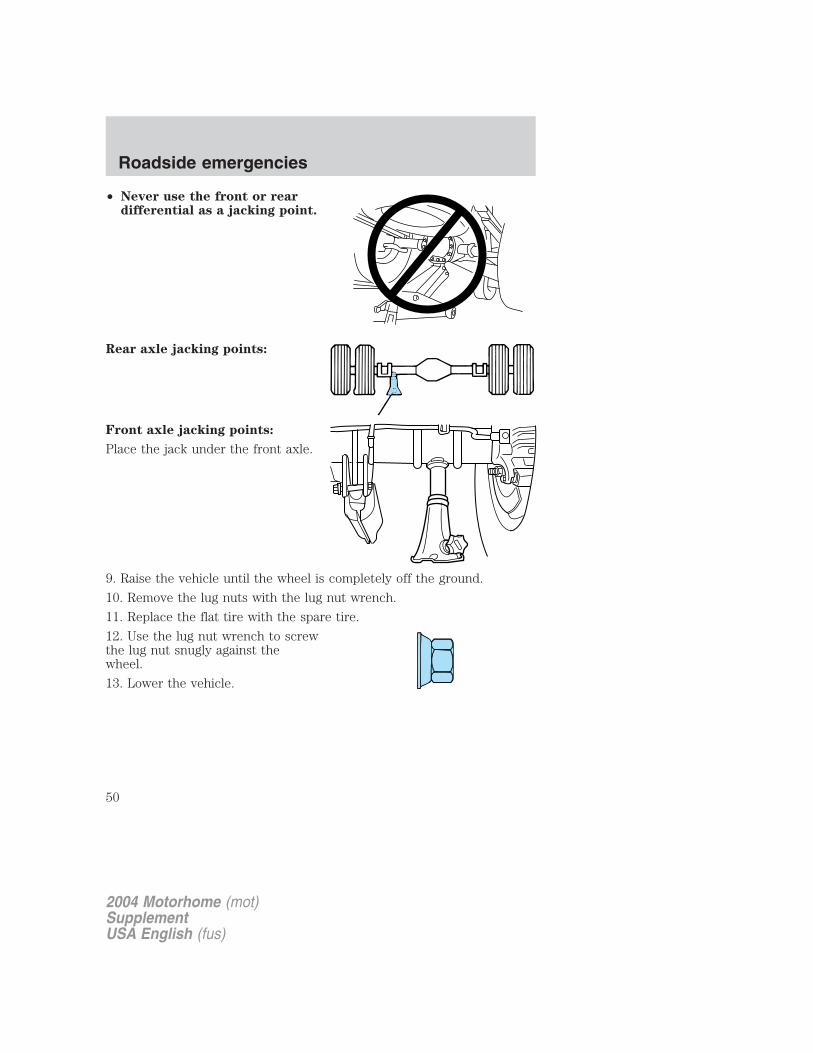
• Never use the front or reardifferential as a jacking point.
Rear axle jacking points:
Front axle jacking points:
Place the jack under the front axle.
9. Raise the vehicle until the wheel is completely off the ground.
10. Remove the lug nuts with the lug nut wrench.
11. Replace the flat tire with the spare tire.
12. Use the lug nut wrench to screwthe lug nut snugly against thewheel.
13. Lower the vehicle.
2004 Motorhome (mot)SupplementUSA English (fus)
Roadside emergencies
50
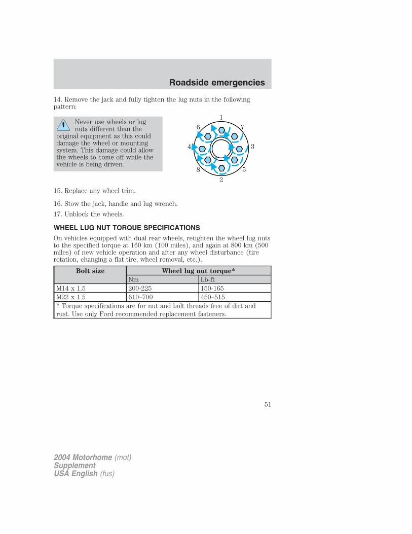
14. Remove the jack and fully tighten the lug nuts in the followingpattern:
Never use wheels or lugnuts different than the
original equipment as this coulddamage the wheel or mountingsystem. This damage could allowthe wheels to come off while thevehicle is being driven.
15. Replace any wheel trim.
16. Stow the jack, handle and lug wrench.
17. Unblock the wheels.
WHEEL LUG NUT TORQUE SPECIFICATIONS
On vehicles equipped with dual rear wheels, retighten the wheel lug nutsto the specified torque at 160 km (100 miles), and again at 800 km (500miles) of new vehicle operation and after any wheel disturbance (tirerotation, changing a flat tire, wheel removal, etc.).
Bolt size Wheel lug nut torque*
Nm Lb-ftM14 x 1.5 200-225 150-165M22 x 1.5 610–700 450–515* Torque specifications are for nut and bolt threads free of dirt andrust. Use only Ford recommended replacement fasteners.
1
34
2
76
58
2004 Motorhome (mot)SupplementUSA English (fus)
Roadside emergencies
51
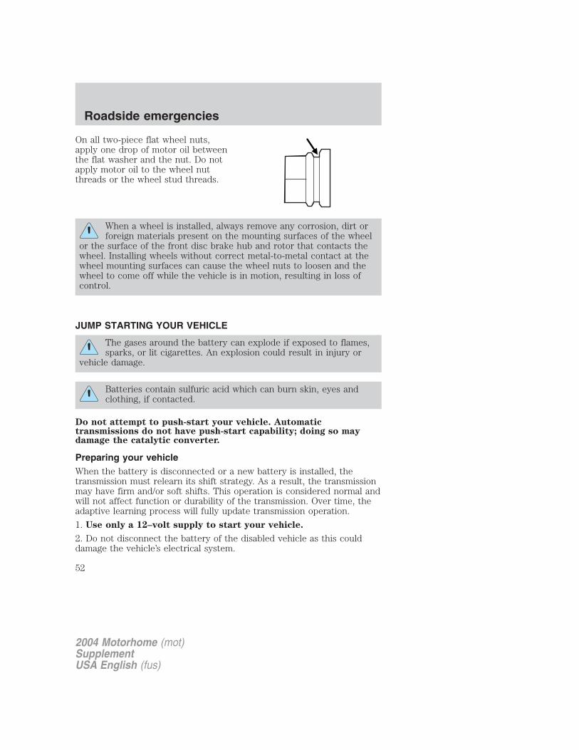
On all two-piece flat wheel nuts,apply one drop of motor oil betweenthe flat washer and the nut. Do notapply motor oil to the wheel nutthreads or the wheel stud threads.
When a wheel is installed, always remove any corrosion, dirt orforeign materials present on the mounting surfaces of the wheel
or the surface of the front disc brake hub and rotor that contacts thewheel. Installing wheels without correct metal-to-metal contact at thewheel mounting surfaces can cause the wheel nuts to loosen and thewheel to come off while the vehicle is in motion, resulting in loss ofcontrol.
JUMP STARTING YOUR VEHICLE
The gases around the battery can explode if exposed to flames,sparks, or lit cigarettes. An explosion could result in injury or
vehicle damage.
Batteries contain sulfuric acid which can burn skin, eyes andclothing, if contacted.
Do not attempt to push-start your vehicle. Automatictransmissions do not have push-start capability; doing so maydamage the catalytic converter.
Preparing your vehicleWhen the battery is disconnected or a new battery is installed, thetransmission must relearn its shift strategy. As a result, the transmissionmay have firm and/or soft shifts. This operation is considered normal andwill not affect function or durability of the transmission. Over time, theadaptive learning process will fully update transmission operation.
1. Use only a 12–volt supply to start your vehicle.
2. Do not disconnect the battery of the disabled vehicle as this coulddamage the vehicle’s electrical system.
2004 Motorhome (mot)SupplementUSA English (fus)
Roadside emergencies
52

3. Park the booster vehicle close to the hood of the disabled vehiclemaking sure the two vehicles do not touch. Set the parking brake onboth vehicles and stay clear of the engine cooling fan and other movingparts.
4. Check all battery terminals and remove any excessive corrosion beforeyou attach the battery cables. Ensure that vent caps are tight and level.
5. Turn the heater fan on in both vehicles to protect any electricalsurges. Turn all other accessories off.
Connecting the jumper cables
1. Connect the positive (+) jumper cable to the positive (+) terminal ofthe discharged battery.
Note: In the illustrations, lightning bolts are used to designate theassisting (boosting) battery.
2. Connect the other end of the positive (+) cable to the positive (+)terminal of the assisting battery.
+–
+–
+–
+–
2004 Motorhome (mot)SupplementUSA English (fus)
Roadside emergencies
53
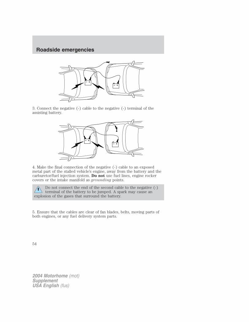
3. Connect the negative (-) cable to the negative (-) terminal of theassisting battery.
4. Make the final connection of the negative (-) cable to an exposedmetal part of the stalled vehicle’s engine, away from the battery and thecarburetor/fuel injection system. Do not use fuel lines, engine rockercovers or the intake manifold as grounding points.
Do not connect the end of the second cable to the negative (-)terminal of the battery to be jumped. A spark may cause an
explosion of the gases that surround the battery.
5. Ensure that the cables are clear of fan blades, belts, moving parts ofboth engines, or any fuel delivery system parts.
+–
+–
+–
+–
2004 Motorhome (mot)SupplementUSA English (fus)
Roadside emergencies
54
Jump starting
1. Start the engine of the booster vehicle and run the engine atmoderately increased speed.
2. Start the engine of the disabled vehicle.
3. Once the disabled vehicle has been started, run both engines for anadditional three minutes before disconnecting the jumper cables.
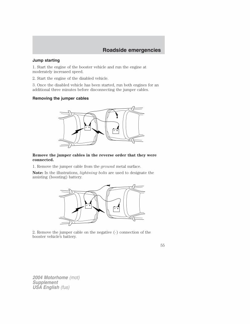
Removing the jumper cables
Remove the jumper cables in the reverse order that they were
connected.
1. Remove the jumper cable from the ground metal surface.
Note: In the illustrations, lightning bolts are used to designate theassisting (boosting) battery.
2. Remove the jumper cable on the negative (-) connection of thebooster vehicle’s battery.
+–
+–
+–
+–
2004 Motorhome (mot)SupplementUSA English (fus)
Roadside emergencies
55
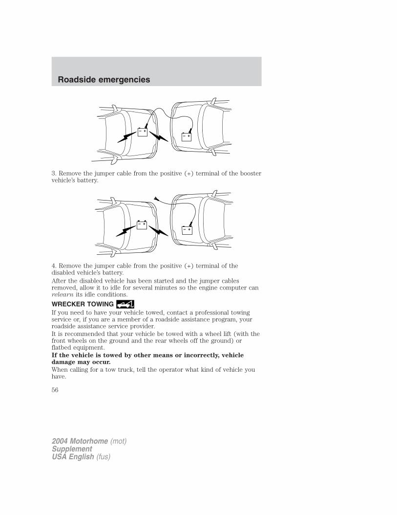
3. Remove the jumper cable from the positive (+) terminal of the boostervehicle’s battery.
4. Remove the jumper cable from the positive (+) terminal of thedisabled vehicle’s battery.After the disabled vehicle has been started and the jumper cablesremoved, allow it to idle for several minutes so the engine computer canrelearn its idle conditions.
WRECKER TOWINGIf you need to have your vehicle towed, contact a professional towingservice or, if you are a member of a roadside assistance program, yourroadside assistance service provider.It is recommended that your vehicle be towed with a wheel lift (with thefront wheels on the ground and the rear wheels off the ground) orflatbed equipment.If the vehicle is towed by other means or incorrectly, vehicledamage may occur.
When calling for a tow truck, tell the operator what kind of vehicle youhave.
+–
+–
+–
+–
2004 Motorhome (mot)SupplementUSA English (fus)
Roadside emergencies
56

GETTING THE SERVICES YOU NEED
At homeYou must take your Ford vehicle to an authorized Ford dealer forwarranty repairs. While any Ford dealership handling your vehicle linewill provide warranty service, we recommend you return to your sellingdealer who wants to ensure your continued satisfaction. Please note thatcertain warranty repairs require special training and/or equipment, so notall dealers are authorized to perform all warranty repairs. This meansthat, depending on the warranty repair needed, you may have to takeyour vehicle to another dealer. In certain instances, Ford may authorizethat your vehicle be repaired at a repair center other than a Ford dealerfacility. A reasonable time must be allowed to perform a repair aftertaking your vehicle to the dealership. Repairs will be made using Ford orMotorcraft parts, or remanufactured or other parts that are authorized byFord.
If you have questions or concerns, or are unsatisfied with the service youare receiving, follow these steps:
1. Contact your Sales Representative or Service Advisor at yourselling/servicing dealership.
2. If your inquiry or concern remains unresolved, contact the SalesManager Service Manager or Customer Relations Manager.
3. If you require assistance or clarification on Ford Motor Companypolicies or procedures, please contact the Ford Customer RelationshipCenter at the number below.
Away from homeIf you own a motorhome built on a Ford Chassis and are away fromhome when your vehicle needs service, or if you need more help thanthe dealership could provide, after following the steps above, contact theFord Motorhome Customer Assistance Center to find an authorizeddealership or service location to help you. In the United States andCanada:Ford Motorhome Customer Assistance Center900 N. Lake Havasu AvenueLake Havasu City, AZ1-800-444-3311Open 365/24/7
2004 Motorhome (mot)SupplementUSA English (fus)
Customer assistance
Customer assistance
57
In order to help service your motorhome vehicle, please have thefollowing information available when contacting the MotorhomeCustomer Assistance Center:
• telephone number where you can be reached
• vehicle location (city and state)
• year and make of your vehicle
• date of vehicle purchase
• current odometer reading
• vehicle identification number (VIN).
FORD EXTENDED SERVICE PLANYou can get more protection for your new car or light truck bypurchasing Ford Extended Service Plan (Ford ESP) coverage. Ford ESPis an optional service contract which is backed by Ford Motor Companyor Ford Motor Service Company (in the U.S.) and Ford of Canada (inCanada). It provides the following:
• Benefits during the warranty period depending on the plan youpurchase (such as: reimbursement for rentals; coverage for certainmaintenance and wear items).
• Protection against covered repair costs after your Bumper-to-BumperWarranty expires.
You may purchase Ford ESP from any participating Ford and LincolnMercury and Ford of Canada dealer. There are several plans available invarious time, distance and deductible combinations which can be tailoredto fit your own driving needs. Ford ESP also offers reimbursementbenefits for towing and rental coverage.
When you buy Ford ESP, you receive Peace-of-Mind protectionthroughout the United States and Canada, provided by a network ofmore than 5,000 participating Ford or Lincoln Mercury and Ford ofCanada dealers.
If you did not take advantage of the Ford Extended Service Plan at thetime of purchasing your vehicle, you may still be eligible. Since thisinformation is subject to change, please ask your dealer for completedetails about Ford Extended Service Plan coverage options, or visit theFord ESP website at www.ford-esp.com.
2004 Motorhome (mot)SupplementUSA English (fus)
Customer assistance
58
THE DISPUTE SETTLEMENT BOARD (U.S. ONLY)
The Dispute Settlement Board is:
• an independent, third-party arbitration program for warranty disputes.
• available free to owners and lessees of qualifying Ford Motor Companyvehicles.
The Dispute Settlement Board may not be available in all states. FordMotor Company reserves the right to change eligibility limitations, modifyprocedures and/or to discontinue this service without notice and withoutincurring obligations per applicable state law.
What kinds of cases does the Board review?Unresolved warranty repair concerns or vehicle performance concerns ason Ford and Lincoln Mercury cars and Ford and Lincoln Mercury lighttrucks which are within the terms of any applicable written new vehiclewarranty are eligible for review, except those involving:
• a non-Ford product
• a non-Ford dealership
• sales disputes between customer and dealer except those associatedwith warranty repairs or concerns with the vehicle’s performance asdesigned
• a request for reimbursement of consequential expenses unless aservice or product concern is being reviewed
• items not covered by the New Vehicle Limited Warranty (includingmaintenance and wear items)
• alleged personal injury/property damage claims
• cases currently in litigation
• vehicles not used primarily for family, personal or household purposes(except in states where the Dispute Settlement Board is required toreview commercial vehicles)
• vehicles with non-U.S. warranties
Concerns are ineligible for review if the New Vehicle Limited Warrantyhas expired at receipt of your application and, in certain states eligibilityis dependent upon the customer’s possession of the vehicle.
Eligibility may differ according to state law. For example, see the uniquebrochures for California, West Virginia, Georgia and Wisconsinpurchasers/lessees.
2004 Motorhome (mot)SupplementUSA English (fus)
Customer assistance
59

Board membershipThe Board consists of:• Three consumer representatives• A Ford or Lincoln Mercury dealership representativeConsumer candidates for Board membership are recruited and trained byan independent consulting firm. The dealership Board member is chosenfrom Ford and Lincoln Mercury dealership management, recognized fortheir business leadership qualities.
What the Board needsTo have your case reviewed you must complete the application in theDSB brochure and mail it to the address provided on the applicationform. Some states will require you to use certified mail, with returnreceipt requested.
Your application is reviewed and, if it is determined to be eligible, youwill receive an acknowledgment indicating:
• The file number assigned to your application.
• The toll-free phone number of the DSB’s independent administrator.
Your dealership and a Ford Motor Company representative will then beasked to submit statements.
To properly review your case, the Board needs the following information:
• Legible copies of all documents and maintenance or repair ordersrelevant to the case.
• The year, make, model, and Vehicle Identification Number (VIN) listedon your vehicle ownership license.
• The date of repair(s) and mileage at the time of occurrence(s).
• The current mileage.
• The name of the dealer(s) who sold or serviced the vehicle.
• A brief description of your unresolved concern.
• A brief summary of the action taken by the dealer(s) and Ford MotorCompany.
• The names (if known) of all the people you contacted at thedealership(s).
• A description of the action you expect to resolve your concern.
You will receive a letter of explanation if your application does notqualify for Board review.
2004 Motorhome (mot)SupplementUSA English (fus)
Customer assistance
60

Oral presentationsIf you would like to make an oral presentation, indicate YES to question6 on the application. While it is your right to make an oral presentationbefore the Board, this is not a requirement and the Board will decide thecase whether or not an oral presentation is made. An oral presentationmay be requested by the Board as well.
Making a decisionBoard members review all available information related to eachcomplaint, including oral presentations, and arrive at a fair and impartialdecision. Board review may be terminated at any time by either party.
Every effort is made to decide the case within 40 days of the date thatall requested information is received by the Board. Since the Boardgenerally meets once a month, it may take longer for the Board toconsider some cases.
After a case is reviewed, the Board mails you a decision letter and aform on which to accept or reject the Board’s decision. The decisions ofthe Board are binding on Ford (and, in some cases, on the dealer) butnot on consumers who are free to pursue other remedies available tothem under state or federal law.
To request a DSB Brochure/ApplicationFor a brochure/application, speak to your dealer or write/call to theBoard at the following address/phone number:
Dispute Settlement BoardP.O. Box 5120Southfield, MI 48086–51201–800–428–3718
You may also contact the North American Customer Relationship Centerat 1-800-392-3673 (Ford), TDD for the hearing impaired: 1-800-232-5952or by writing to the Center at the following address:
Ford Motor CompanyCustomer Relationship CenterP.O. Box 6248Dearborn, Michigan 48121
2004 Motorhome (mot)SupplementUSA English (fus)
Customer assistance
61

UTILIZING THE MEDIATION/ARBITRATION PROGRAM (CANADAONLY)In those cases where you continue to feel that the efforts by Ford andthe dealer to resolve a factory-related vehicle service concern have beenunsatisfactory, Ford of Canada participates in an impartial third partymediation/arbitration program administered by the Canadian MotorVehicle Arbitration Plan (CAMVAP).
The CAMVAP program is a straight-forward and relatively speedyalternative to resolve a disagreement when all other efforts to produce asettlement have failed. This procedure is without cost to you and isdesigned to eliminate the need for lengthy and expensive legalproceedings.
In the CAMVAP program, impartial third-party arbitrators conducthearings at mutually convenient times and places in an informalenvironment. These impartial arbitrators review the positions of theparties, make decisions and, when appropriate, render awards to resolvedisputes. CAMVAP decisions are fast, fair, and final; the arbitrator’saward is binding both to you and Ford of Canada.
CAMVAP services are available in all territories and provinces. For moreinformation, without charge or obligation, call your CAMVAP ProvincialAdministrator directly at 1-800-207-0685.
GETTING ASSISTANCE OUTSIDE THE U.S. AND CANADABefore exporting your vehicle to a foreign country, contact theappropriate foreign embassy or consulate. These officials can inform youof local vehicle registration regulations and where to find unleaded fuel.
If you cannot find unleaded fuel or can only get fuel with an anti-knockindex lower than is recommended for your vehicle, contact a district orowner relations/customer relationship office.
The use of leaded fuel in your vehicle without proper conversion maydamage the effectiveness of your emission control system and may causeengine knocking or serious engine damage. Ford Motor Company/Ford ofCanada is not responsible for any damage caused by use of improperfuel.
In the United States, using leaded fuel may also result in difficultyimporting your vehicle back into the U.S.
2004 Motorhome (mot)SupplementUSA English (fus)
Customer assistance
62

If your vehicle must be serviced while you are traveling or living inCentral or South America, the Caribbean, or the Middle East, contact thenearest Ford dealership. If the dealership cannot help you, write or call:
FORD MOTOR COMPANYWORLDWIDE DIRECT MARKET OPERATIONS1555 Fairlane DriveFairlane Business Park #3Allen Park, Michigan 48101U.S.A.Telephone: (313) 594-4857FAX: (313) 390-0804
If you are in another foreign country, contact the nearest Forddealership. If the dealership employees cannot help you, they can directyou to the nearest Ford affiliate office.
If you buy your vehicle in North America and then relocate outside ofthe U.S. or Canada, register your vehicle identification number (VIN) andnew address with Ford Motor Company Worldwide Direct MarketOperations.
ORDERING ADDITIONAL OWNER’S LITERATURETo order the publications in this portfolio, contact Helm, Incorporated at:
HELM, INCORPORATEDP.O. Box 07150Detroit, Michigan 48207
Or call:
For a free publication catalog, order toll free: 1-800-782-4356
Monday-Friday 8:00 a.m. - 6:00 p.m. EST
Helm, Incorporated can also be reached by their website:www.helminc.com.
(Items in this catalog may be purchased by credit card, check ormoney order.)
Obtaining a French owner’s guideFrench Owner’s Guides can be obtained from your dealer or by writing toFord Motor Company of Canada, Limited, Service Publications, P.O. Box1580, Station B, Mississauga, Ontario L4Y 4G3.
2004 Motorhome (mot)SupplementUSA English (fus)
Customer assistance
63

IN CALIFORNIA (U.S. ONLY)California Civil Code Section 1793.2(d) requires that, if a manufactureror its representative is unable to repair a motor vehicle to conform to thevehicle’s applicable express warranty after a reasonable number ofattempts, the manufacturer shall be required to either replace thevehicle with one substantially identical or repurchase the vehicle andreimburse the buyer in an amount equal to the actual price paid orpayable by the consumer (less a reasonable allowance for consumeruse). The consumer has the right to choose whether to receive a refundor replacement vehicle.
California Civil Code Section 1793.22(b) presumes that the manufacturerhas had a reasonable number of attempts to conform the vehicle to itsapplicable express warranties if, within the first 18 months of ownershipof a new vehicle or the first 29,000 km (18,000 miles), whichever occursfirst:
1. Two or more repair attempts are made on the same nonconformitylikely to cause death or serious bodily injury OR
2. Four or more repair attempts are made on the same nonconformity (adefect or condition that substantially impairs the use, value or safety ofthe vehicle) OR
3. The vehicle is out of service for repair of nonconformities for a total ofmore than 30 calendar days (not necessarily all at one time)
In the case of 1 or 2 above, the consumer must also notify themanufacturer of the need for the repair of the nonconformity at thefollowing address:
Ford Motor Company16800 Executive Plaza DriveMail Drop 3NE-BDearborn, MI 48126
2004 Motorhome (mot)SupplementUSA English (fus)
Customer assistance
64
REPORTING SAFETY DEFECTS (U.S. ONLY)If you believe that your vehicle hasa defect which could cause a crashor could cause injury or death, youshould immediately inform the National Highway Traffic SafetyAdministration (NHTSA) in addition to notifying Ford Motor Company.
If NHTSA receives similar complaints, it may open an investigation, andif it finds that a safety defect exists in a group of vehicles, it may order arecall and remedy campaign. However, NHTSA cannot become involvedin individual problems between you, your dealer, or Ford MotorCompany.
To contact NHTSA, you may either call the Auto Safety Hotline toll-freeat 1–800–424–9393 (or 366–0123 in the Washington D.C. area) or writeto:
NHTSA400 Seventh StreetU.S. Department of TransportationWashington, D.C. 20590
You can also obtain other information about motor vehicle safety fromthe Hotline.
2004 Motorhome (mot)SupplementUSA English (fus)
Customer assistance
65

CLEANING THE WHEELS• Clean weekly with Motorcraft Wheel and Tire Cleaner (ZC-37–A),
which is available from your dealer. Heavy dirt and brake dustaccumulation may require agitation with a sponge. Rinse thoroughlywith a strong stream of water.
• Never apply any cleaning chemical to hot or warm wheel rims orcovers.
• Some automatic car washes may cause damage to the finish on yourwheel rims or covers. Chemical-strength cleaners, or cleaningchemicals, in combination with brush agitation to remove brake dustand dirt, could wear away the clearcoat finish over time.
• Do not use hydrofluoric acid-based or high caustic-based wheelcleaners, steel wool, fuels or strong household detergent.
• To remove tar and grease, use Motorcraft Bug and Tar Remover(ZC-42), available from your dealer.
ENGINEEngines are more efficient when they are clean because grease and dirtbuildup keep the engine warmer than normal. When washing:
• Take care when using a power washer to clean the engine. Thehigh-pressure fluid could penetrate the sealed parts and causedamage.
• Do not spray a hot engine with cold water to avoid cracking theengine block or other engine components.
• Spray Motorcraft Engine Shampoo and Degreaser (ZC-20) on all partsthat require cleaning and pressure rinse clean.
• Never wash or rinse the engine while it is running; water in therunning engine may cause internal damage.
UNDERBODYFlush the complete underside of your vehicle frequently. Keep body anddoor drain holes free from packed dirt.
2004 Motorhome (mot)SupplementUSA English (fus)
Cleaning
Cleaning
66
SERVICE RECOMMENDATIONS
To help you service your vehicle:
• We highlight do-it-yourself items in the engine compartment for easylocation.
• We provide a scheduled maintenance guide which makes trackingroutine service easy.
If your vehicle requires professional service, your dealership can providethe necessary parts and service. Check your Warranty Guide/OwnerInformation Guide to find out which parts and services are covered.
Use only recommended fuels, lubricants, fluids and service partsconforming to specifications. Motorcraft parts are designed and built toprovide the best performance in your vehicle.
PRECAUTIONS WHEN SERVICING YOUR VEHICLE
• Do not work on a hot engine.
• Make sure that nothing gets caught in moving parts.
• Do not work on a vehicle with the engine running in an enclosedspace, unless you are sure you have enough ventilation.
• Keep all open flames and other lit material away from the battery andall fuel related parts.
Working with the engine off
1. Set the parking brake and shift to P (Park).
2. Turn off the engine and remove the key.
3. Block the wheels.
Working with the engine on
1. Set the parking brake and shift to P (Park).
2. Block the wheels.
Note: Do not start your engine with the air cleaner removed and do notremove it while the engine is running.
2004 Motorhome (mot)SupplementUSA English (fus)
Maintenance and specifications
Maintenance and specifications
67
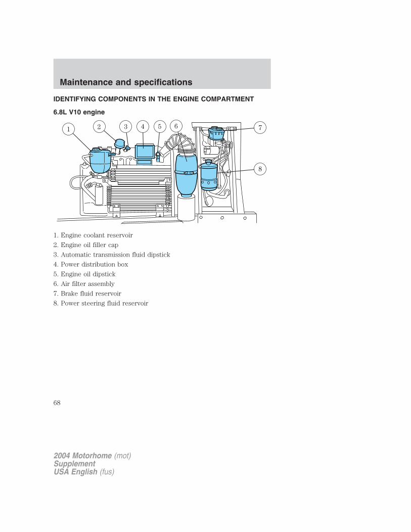
IDENTIFYING COMPONENTS IN THE ENGINE COMPARTMENT
6.8L V10 engine
1. Engine coolant reservoir
2. Engine oil filler cap
3. Automatic transmission fluid dipstick
4. Power distribution box
5. Engine oil dipstick
6. Air filter assembly
7. Brake fluid reservoir
8. Power steering fluid reservoir
2004 Motorhome (mot)SupplementUSA English (fus)
Maintenance and specifications
68
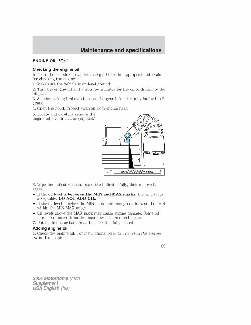
ENGINE OIL
Checking the engine oilRefer to the scheduled maintenance guide for the appropriate intervalsfor checking the engine oil.1. Make sure the vehicle is on level ground.2. Turn the engine off and wait a few minutes for the oil to drain into theoil pan.3. Set the parking brake and ensure the gearshift is securely latched in P(Park).4. Open the hood. Protect yourself from engine heat.
5. Locate and carefully remove theengine oil level indicator (dipstick).
6. Wipe the indicator clean. Insert the indicator fully, then remove itagain.• If the oil level is between the MIN and MAX marks, the oil level is
acceptable. DO NOT ADD OIL.
• If the oil level is below the MIN mark, add enough oil to raise the levelwithin the MIN-MAX range.
• Oil levels above the MAX mark may cause engine damage. Some oilmust be removed from the engine by a service technician.
7. Put the indicator back in and ensure it is fully seated.
Adding engine oil1. Check the engine oil. For instructions, refer to Checking the engineoil in this chapter.
2004 Motorhome (mot)SupplementUSA English (fus)
Maintenance and specifications
69
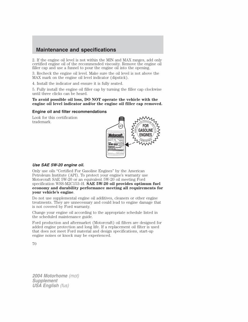
2. If the engine oil level is not within the MIN and MAX ranges, add onlycertified engine oil of the recommended viscosity. Remove the engine oilfiller cap and use a funnel to pour the engine oil into the opening.3. Recheck the engine oil level. Make sure the oil level is not above theMAX mark on the engine oil level indicator (dipstick).
4. Install the indicator and ensure it is fully seated.
5. Fully install the engine oil filler cap by turning the filler cap clockwiseuntil three clicks can be heard.
To avoid possible oil loss, DO NOT operate the vehicle with theengine oil level indicator and/or the engine oil filler cap removed.
Engine oil and filter recommendationsLook for this certificationtrademark.
Use SAE 5W-20 engine oil.Only use oils “Certified For Gasoline Engines” by the AmericanPetroleum Institute (API). To protect your engine’s warranty useMotorcraft SAE 5W-20 or an equivalent 5W-20 oil meeting Fordspecification WSS-M2C153–H. SAE 5W-20 oil provides optimum fueleconomy and durability performance meeting all requirements foryour vehicle’s engine.
Do not use supplemental engine oil additives, cleaners or other enginetreatments. They are unnecessary and could lead to engine damage thatis not covered by Ford warranty.
Change your engine oil according to the appropriate schedule listed inthe scheduled maintenance guide.
Ford production and aftermarket (Motorcraft) oil filters are designed foradded engine protection and long life. If a replacement oil filter is usedthat does not meet Ford material and design specifications, start-upengine noises or knock may be experienced.
2004 Motorhome (mot)SupplementUSA English (fus)
Maintenance and specifications
70
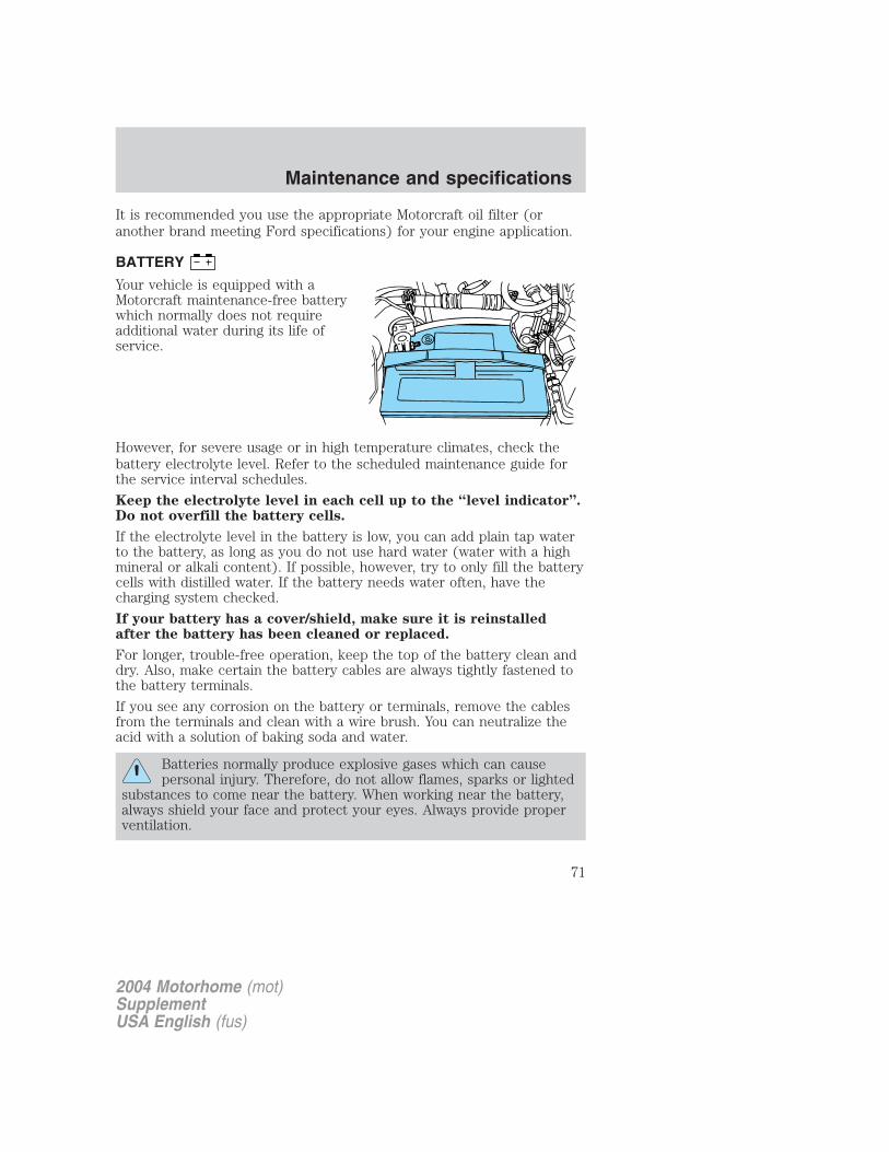
It is recommended you use the appropriate Motorcraft oil filter (oranother brand meeting Ford specifications) for your engine application.
BATTERY
Your vehicle is equipped with aMotorcraft maintenance-free batterywhich normally does not requireadditional water during its life ofservice.
However, for severe usage or in high temperature climates, check thebattery electrolyte level. Refer to the scheduled maintenance guide forthe service interval schedules.
Keep the electrolyte level in each cell up to the “level indicator”.Do not overfill the battery cells.
If the electrolyte level in the battery is low, you can add plain tap waterto the battery, as long as you do not use hard water (water with a highmineral or alkali content). If possible, however, try to only fill the batterycells with distilled water. If the battery needs water often, have thecharging system checked.
If your battery has a cover/shield, make sure it is reinstalledafter the battery has been cleaned or replaced.
For longer, trouble-free operation, keep the top of the battery clean anddry. Also, make certain the battery cables are always tightly fastened tothe battery terminals.
If you see any corrosion on the battery or terminals, remove the cablesfrom the terminals and clean with a wire brush. You can neutralize theacid with a solution of baking soda and water.
Batteries normally produce explosive gases which can causepersonal injury. Therefore, do not allow flames, sparks or lighted
substances to come near the battery. When working near the battery,always shield your face and protect your eyes. Always provide properventilation.
2004 Motorhome (mot)SupplementUSA English (fus)
Maintenance and specifications
71
When lifting a plastic-cased battery, excessive pressure on theend walls could cause acid to flow through the vent caps,
resulting in personal injury and/or damage to the vehicle or battery.Lift the battery with a battery carrier or with your hands on oppositecorners.
Keep batteries out of reach of children. Batteries contain sulfuricacid. Avoid contact with skin, eyes or clothing. Shield your eyes
when working near the battery to protect against possible splashing ofacid solution. In case of acid contact with skin or eyes, flushimmediately with water for a minimum of 15 minutes and get promptmedical attention. If acid is swallowed, call a physician immediately.
Battery posts, terminals and related accessories contain lead andlead compounds. Wash hands after handling.
To account for customer driving habits and conditions, your automatictransmission (4R100) electronically controls the shift quality by using anadaptive learning strategy. The adaptive learning strategy is maintainedby power from the battery. When the battery is disconnected or a newbattery is installed, the transmission must relearn its adaptive strategy.Optimal shifting will resume within a few hundred kilometers (miles) ofoperation.
If the shift quality does not improve within a few hundredkilometers (miles) of operation, or if the downshifts and otherthrottle conditions do not function normally or after a longdeceleration period, see your dealer or a qualified servicetechnician as soon as possible.
Because your vehicle’s engine is also electronically controlled by acomputer, some control conditions are maintained by power from thebattery. When the battery is disconnected or a new battery is installed,the engine must relearn its idle and fuel trim strategy for optimumdriveability and performance. To begin this process:
1. With the vehicle at a complete stop, set the parking brake.
2. Put the gearshift in P (Park), turn off all accessories and start theengine.
3. Run the engine until it reaches normal operating temperature.
4. Allow the engine to idle for at least one minute.
2004 Motorhome (mot)SupplementUSA English (fus)
Maintenance and specifications
72
5. Turn the A/C on and allow the engine to idle for at least one minute.6. With your foot on the brake pedal and with the A/C on, put thevehicle in D (Drive) and allow the engine to idle for at least one minute.7. Drive the vehicle to complete the relearning process.• The vehicle may need to be driven 16 km (10 miles) or more to
relearn the idle and fuel trim strategy.• If you do not allow the engine to relearn its idle trim, the idle
quality of your vehicle may be adversely affected until the idletrim is eventually relearned.
If the battery has been disconnected or a new battery has been installed,the clock and the preset radio stations must be reset once the battery isreconnected.
• Always dispose of automotivebatteries in a responsible manner.Follow your local authorizedstandards for disposal. Call yourlocal authorized recycling centerto find out more about recyclingautomotive batteries.
ENGINE COOLANT
Checking engine coolantThe concentration and level of engine coolant should be checked at themileage intervals listed in the scheduled maintenance guide. The coolantconcentration should be maintained at 50/50 coolant and distilled water,which equates to a freeze point of -36° C (-34° F). Coolant concentrationtesting is possible with a hydrometer or antifreeze tester (such as theRotunda Battery and Antifreeze Tester, 014–R1060). The level of coolantshould be maintained at the “cold full” of “cold fill range” level in thecoolant reservoir. If the level falls below, add coolant per the instructionsin the Adding engine coolant section.
Your vehicle was factory-filled with a 50/50 engine coolant and waterconcentration. If the concentration of coolant falls below 40% or above60%, the engine parts could become damaged or not work properly. A50–50 mixture of coolant and water provides the following:
• Freeze protection down to -36° C (-34° F).
LE
AD
RE
TU
RN
RECYCLE
2004 Motorhome (mot)SupplementUSA English (fus)
Maintenance and specifications
73
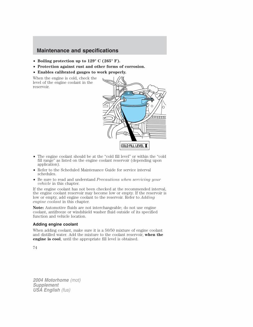
• Boiling protection up to 129° C (265° F).
• Protection against rust and other forms of corrosion.
• Enables calibrated gauges to work properly.
When the engine is cold, check thelevel of the engine coolant in thereservoir.
• The engine coolant should be at the “cold fill level” or within the “coldfill range” as listed on the engine coolant reservoir (depending uponapplication).
• Refer to the Scheduled Maintenance Guide for service intervalschedules.
• Be sure to read and understand Precautions when servicing yourvehicle in this chapter.
If the engine coolant has not been checked at the recommended interval,the engine coolant reservoir may become low or empty. If the reservoir islow or empty, add engine coolant to the reservoir. Refer to Addingengine coolant in this chapter.
Note: Automotive fluids are not interchangeable; do not use enginecoolant, antifreeze or windshield washer fluid outside of its specifiedfunction and vehicle location.
Adding engine coolantWhen adding coolant, make sure it is a 50/50 mixture of engine coolantand distilled water. Add the mixture to the coolant reservoir, when theengine is cool, until the appropriate fill level is obtained.
COLD FILL LEVEL
2004 Motorhome (mot)SupplementUSA English (fus)
Maintenance and specifications
74
Do not add engine coolant when the engine is hot. Steam andscalding liquids released from a hot cooling system can burn you
badly. Also, you can be burned if you spill coolant on hot engine parts.
Do not put engine coolant in the windshield washer fluidcontainer. If sprayed on the windshield, engine coolant could
make it difficult to see through the windshield.
• Add Motorcraft Premium Gold Engine Coolant(yellow-colored), VC-7–A (VC-7–B in Oregon and California),meeting Ford Specification WSS-M97B51–A1.
Note: Use of Motorcraft Cooling System Stop Leak Pellets, VC-6, maydarken the color of Motorcraft Premium Gold Engine Coolant fromyellow to golden tan.• Do not add/mix an orange-colored, extended life coolant such
as Motorcraft Speciality Orange Engine Coolant, VC-2 (US) orCXC-209 (Canada), meeting Ford specification WSS-M97B44–Dwith the factory-filled coolant. Mixing Motorcraft Speciality OrangeEngine Coolant or any orange-colored extended life product with yourfactory filled coolant can result in degraded corrosion protection.
• A large amount of water without engine coolant may be added, in caseof emergency, to reach a vehicle service location. In this instance, thecooling system must be drained and refilled with a 50/50 mixture ofengine coolant and distilled water as soon as possible. Water alone(without engine coolant) can cause engine damage from corrosion,overheating or freezing.
• Do not use alcohol, methanol, brine or any engine coolantsmixed with alcohol or methanol antifreeze (coolant). Alcoholand other liquids can cause engine damage from overheating orfreezing.
• Do not add extra inhibitors or additives to the coolant. Thesecan be harmful and compromise the corrosion protection of the enginecoolant.
For vehicles with overflow coolant systems with a non-pressurized capon the coolant recovery system, add coolant to the coolant recoveryreservoir when the engine is cool. Add the proper mixture of coolant andwater to the “cold full” level. For all other vehicles, which have a coolantdegas system with a pressurized cap, or if it is necessary to remove thecoolant pressure relief cap on the radiator of a vehicle with an overflowsystem, follow these steps to add engine coolant.
2004 Motorhome (mot)SupplementUSA English (fus)
Maintenance and specifications
75
To reduce the risk of personal injury, make sure the engine iscool before unscrewing the coolant pressure relief cap. The
cooling system is under pressure; steam and hot liquid can come outforcefully when the cap is loosened slightly.
1. Before you begin, turn the engine off and let it cool.2. When the engine is cool, wrap a thick cloth around the coolantpressure relief cap on the coolant reservoir (a translucent plastic bottle).Slowly turn cap counterclockwise (left) until pressure begins to release.3. Step back while the pressure releases.4. When you are sure that all the pressure has been released, use thecloth to turn it counterclockwise and remove the cap.5. Fill the coolant reservoir slowly with the proper coolant mixture (seeabove), to within the “cold fill range” or the “cold full” level on thereservoir. If you removed the radiator cap in an overflow system, fill theradiator until the coolant is visible and radiator is almost full.6. Replace the cap. Turn until tightly installed. (Cap must be tightlyinstalled to prevent coolant loss.)After any coolant has been added, check the coolant concentration, referto Checking Engine Coolant section. If the concentration is not 50/50(protection to –34° F/–36° C), drain some coolant and adjust theconcentration. It may take several drains and additions to obtain a 50/50coolant concentration.Whenever coolant has been added, the coolant level in the coolantreservoir should be checked the next few times you drive the vehicle. Ifnecessary, add enough 50/50 concentration of engine coolant anddistilled water to bring the liquid level to the proper level.If you have to add more than 1.0 liter (1.0 quart) of engine coolant permonth, have your dealer check the engine cooling system. Your coolingsystem may have a leak. Operating an engine with a low level of coolantcan result in engine overheating and possible engine damage.
Recycled engine coolantFord Motor Company does NOT recommend the use of recycled enginecoolant in vehicles originally equipped with Motorcraft Premium GoldEngine Coolant since a Ford-approved recycling process is not yetavailable.
Used engine coolant should be disposed of in an appropriatemanner. Follow your community’s regulations and standards for recyclingand disposing of automotive fluids.
2004 Motorhome (mot)SupplementUSA English (fus)
Maintenance and specifications
76
Coolant refill capacityTo find out how much fluid your vehicle’s cooling system can hold, referto Refill capacities in this chapter.Fill your engine coolant reservoir as outlined in Adding engine coolantin this chapter.
Severe climatesIf you drive in extremely cold climates (less than –36° C [–34° F]):• It may be necessary to increase the coolant concentration
above 50%.
• NEVER increase the coolant concentration above 60%.
• Increased engine coolant concentrations above 60% willdecrease the overheat protection characteristics of the enginecoolant and may cause engine damage.
• Refer to the chart on the coolant container to ensure thecoolant concentration in your vehicle will provide adequatefreeze protection at the temperatures in which you drive in thewinter months.
If you drive in extremely hot climates:• It is still necessary to maintain the coolant concentration
above 40%.
• NEVER decrease the coolant concentration below 40%.
• Decreased engine coolant concentrations below 40% willdecrease the corrosion protection characteristics of the enginecoolant and may cause engine damage.
• Decreased engine coolant concentrations below 40% willdecrease the freeze protection characteristics of the enginecoolant and may cause engine damage.
• Refer to the chart on the coolant container to ensure thecoolant concentration in your vehicle will provide adequateprotection at the temperatures in which you drive.
Vehicles driven year-round in non-extreme climates should use a 50/50mixture of engine coolant and distilled water for optimum cooling systemand engine protection.
What you should know about fail-safe coolingIf the engine coolant supply is depleted, this feature allows the vehicle tobe driven temporarily before incremental component damage is incurred.The “fail-safe” distance depends on ambient temperatures, vehicle loadand terrain.
2004 Motorhome (mot)SupplementUSA English (fus)
Maintenance and specifications
77
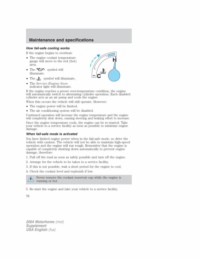
How fail-safe cooling worksIf the engine begins to overheat:
• The engine coolant temperaturegauge will move to the red (hot)area.
• The symbol willilluminate.
• The symbol will illuminate.
• The Service Engine Soonindicator light will illuminate.
If the engine reaches a preset over-temperature condition, the enginewill automatically switch to alternating cylinder operation. Each disabledcylinder acts as an air pump and cools the engine.When this occurs the vehicle will still operate. However:• The engine power will be limited.• The air conditioning system will be disabled.Continued operation will increase the engine temperature and the enginewill completely shut down, causing steering and braking effort to increase.Once the engine temperature cools, the engine can be re-started. Takeyour vehicle to a service facility as soon as possible to minimize enginedamage.
When fail-safe mode is activatedYou have limited engine power when in the fail-safe mode, so drive thevehicle with caution. The vehicle will not be able to maintain high-speedoperation and the engine will run rough. Remember that the engine iscapable of completely shutting down automatically to prevent enginedamage, therefore:
1. Pull off the road as soon as safely possible and turn off the engine.
2. Arrange for the vehicle to be taken to a service facility.
3. If this is not possible, wait a short period for the engine to cool.
4. Check the coolant level and replenish if low.
Never remove the coolant reservoir cap while the engine isrunning or hot.
5. Re-start the engine and take your vehicle to a service facility.
H
C
2004 Motorhome (mot)SupplementUSA English (fus)
Maintenance and specifications
78
Driving the vehicle without repairing the engine problemincreases the chance of engine damage. Take your vehicle to aservice facility as soon as possible.
WHAT YOU SHOULD KNOW ABOUT AUTOMOTIVE FUELS
Important safety precautions
Do not overfill the fuel tank. The pressure in an overfilled tankmay cause leakage and lead to fuel spray and fire.
The fuel system may be under pressure. If the fuel filler cap isventing vapor or if you hear a hissing sound, wait until it stops
before completely removing the fuel filler cap. Otherwise, fuel mayspray out and injure you or others.
If you do not use the proper fuel filler cap, excessive pressure orvacuum in the fuel tank may damage the fuel system or cause
the fuel cap to disengage in a collision, which may result in possiblepersonal injury.
Automotive fuels can cause serious injury or death if misused ormishandled.
Gasoline may contain benzene, which is a cancer-causing agent.
Observe the following guidelines when handling automotive fuel:
• Extinguish all smoking materialsand any open flames beforefueling your vehicle.
• Always turn off the vehicle beforefueling.
• Automotive fuels can be harmfulor fatal if swallowed. Fuel such as gasoline is highly toxic and ifswallowed can cause death or permanent injury. If fuel is swallowed,call a physician immediately, even if no symptoms are immediatelyapparent. The toxic effects of fuel may not be visible for hours.
2004 Motorhome (mot)SupplementUSA English (fus)
Maintenance and specifications
79
• Avoid inhaling fuel vapors. Inhaling too much fuel vapor of any kindcan lead to eye and respiratory tract irritation. In severe cases,excessive or prolonged breathing of fuel vapor can cause seriousillness and permanent injury.
• Avoid getting fuel liquid in your eyes. If fuel is splashed in the eyes,remove contact lenses (if worn), flush with water for 15 minutes andseek medical attention. Failure to seek proper medical attention couldlead to permanent injury.
• Fuels can also be harmful if absorbed through the skin. If fuel issplashed on the skin and/or clothing, promptly remove contaminatedclothing and wash skin thoroughly with soap and water. Repeated orprolonged skin contact with fuel liquid or vapor causes skin irritation.
• Be particularly careful if you are taking “Antabuse” or other forms ofdisulfiram for the treatment of alcoholism. Breathing gasoline vapors, orskin contact could cause an adverse reaction. In sensitive individuals,serious personal injury or sickness may result. If fuel is splashed on theskin, promptly wash skin thoroughly with soap and water. Consult aphysician immediately if you experience an adverse reaction.
When refueling always shut the engine off and never allowsparks or open flames near the filler neck. Never smoke while
refueling. Fuel vapor is extremely hazardous under certain conditions.Care should be taken to avoid inhaling excess fumes.
The flow of fuel through a fuel pump nozzle can produce staticelectricity, which can cause a fire if fuel is pumped into an
ungrounded fuel container.
Use the following guidelines to avoid static build-up when filling anungrounded fuel container:
• Place approved fuel container on the ground.
• DO NOT fill a fuel container while it is in the vehicle (including thecargo area).
• Keep the fuel pump nozzle in contact with the fuel container whilefilling.
• DO NOT use a device that would hold the fuel pump handle in the fillposition.
2004 Motorhome (mot)SupplementUSA English (fus)
Maintenance and specifications
80
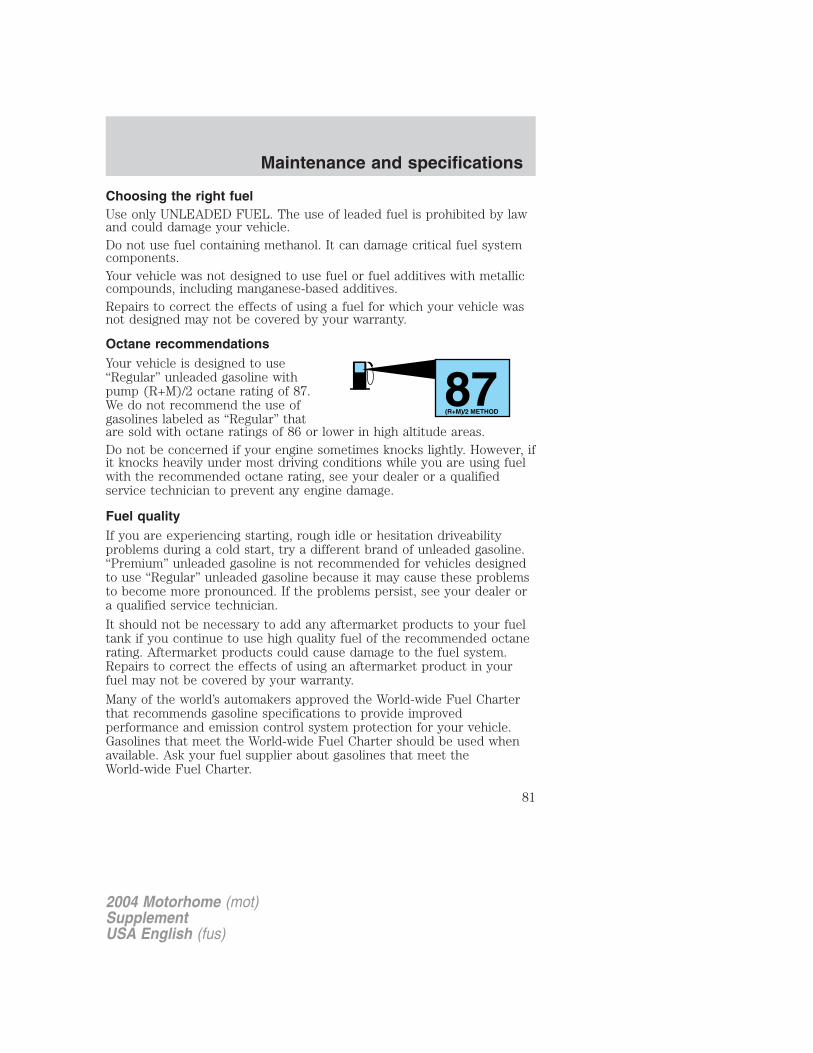
Choosing the right fuelUse only UNLEADED FUEL. The use of leaded fuel is prohibited by lawand could damage your vehicle.Do not use fuel containing methanol. It can damage critical fuel systemcomponents.Your vehicle was not designed to use fuel or fuel additives with metalliccompounds, including manganese-based additives.Repairs to correct the effects of using a fuel for which your vehicle wasnot designed may not be covered by your warranty.
Octane recommendationsYour vehicle is designed to use“Regular” unleaded gasoline withpump (R+M)/2 octane rating of 87.We do not recommend the use ofgasolines labeled as “Regular” thatare sold with octane ratings of 86 or lower in high altitude areas.Do not be concerned if your engine sometimes knocks lightly. However, ifit knocks heavily under most driving conditions while you are using fuelwith the recommended octane rating, see your dealer or a qualifiedservice technician to prevent any engine damage.
Fuel qualityIf you are experiencing starting, rough idle or hesitation driveabilityproblems during a cold start, try a different brand of unleaded gasoline.“Premium” unleaded gasoline is not recommended for vehicles designedto use “Regular” unleaded gasoline because it may cause these problemsto become more pronounced. If the problems persist, see your dealer ora qualified service technician.
It should not be necessary to add any aftermarket products to your fueltank if you continue to use high quality fuel of the recommended octanerating. Aftermarket products could cause damage to the fuel system.Repairs to correct the effects of using an aftermarket product in yourfuel may not be covered by your warranty.
Many of the world’s automakers approved the World-wide Fuel Charterthat recommends gasoline specifications to provide improvedperformance and emission control system protection for your vehicle.Gasolines that meet the World-wide Fuel Charter should be used whenavailable. Ask your fuel supplier about gasolines that meet theWorld-wide Fuel Charter.
87(R+M)/2 METHOD
2004 Motorhome (mot)SupplementUSA English (fus)
Maintenance and specifications
81
Cleaner airFord endorses the use of reformulated “cleaner-burning” gasolines toimprove air quality.
Running out of fuelAvoid running out of fuel because this situation may have an adverseaffect on powertrain components.
If you have run out of fuel:
• You may need to cycle the ignition from OFF to ON several times afterrefueling, to allow the fuel system to pump the fuel from the tank tothe engine.
• Your “Service Engine Soon” indicator may come on. For moreinformation on the “Service Engine Soon” indicator, refer to theInstrument cluster chapter.
Fuel filter replacementThe fuel filter assembly is located inside the driver side frame rail, nearthe transmission.
The fuel filter should be replaced every 24 000 km (15 000 miles).
Removal
If the fuel filter is being serviced with the rear of the vehiclehigher than the front, or if the fuel tank is pressurized, fuel
leakage or siphoning from the tank fuel tubes could occur. To preventthis condition, maintain the vehicle front end at or above the level ofthe rear of the vehicle.
Do not smoke or carry lighted tobacco or open flame of any typewhen working on or near any fuel related component. Highly
flammable mixtures are always present and may be ignited, resulting inpossible personal injury.
Fuel in the fuel system remains under high pressure even whenthe engine is not running. Before servicing or disconnecting any
of the fuel lines or fuel system components, the fuel system pressuremust be relieved in order to prevent accidental spraying of fuel,causing personal injury or a fire hazard.
2004 Motorhome (mot)SupplementUSA English (fus)
Maintenance and specifications
82
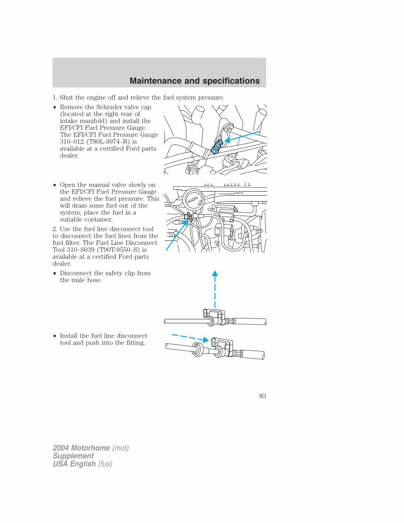
1. Shut the engine off and relieve the fuel system pressure.
• Remove the Schrader valve cap(located at the right rear ofintake manifold) and install theEFI/CFI Fuel Pressure Gauge.The EFI/CFI Fuel Pressure Gauge310–012 (T80L-9974–B) isavailable at a certified Ford partsdealer.
• Open the manual valve slowly onthe EFI/CFI Fuel Pressure Gaugeand relieve the fuel pressure. Thiswill drain some fuel out of thesystem; place the fuel in asuitable container.
2. Use the fuel line disconnect toolto disconnect the fuel lines from thefuel filter. The Fuel Line DisconnectTool 310–S039 (T90T-9550–S) isavailable at a certified Ford partsdealer.
• Disconnect the safety clip fromthe male hose.
• Install the fuel line disconnecttool and push into the fitting.
2004 Motorhome (mot)SupplementUSA English (fus)
Maintenance and specifications
83
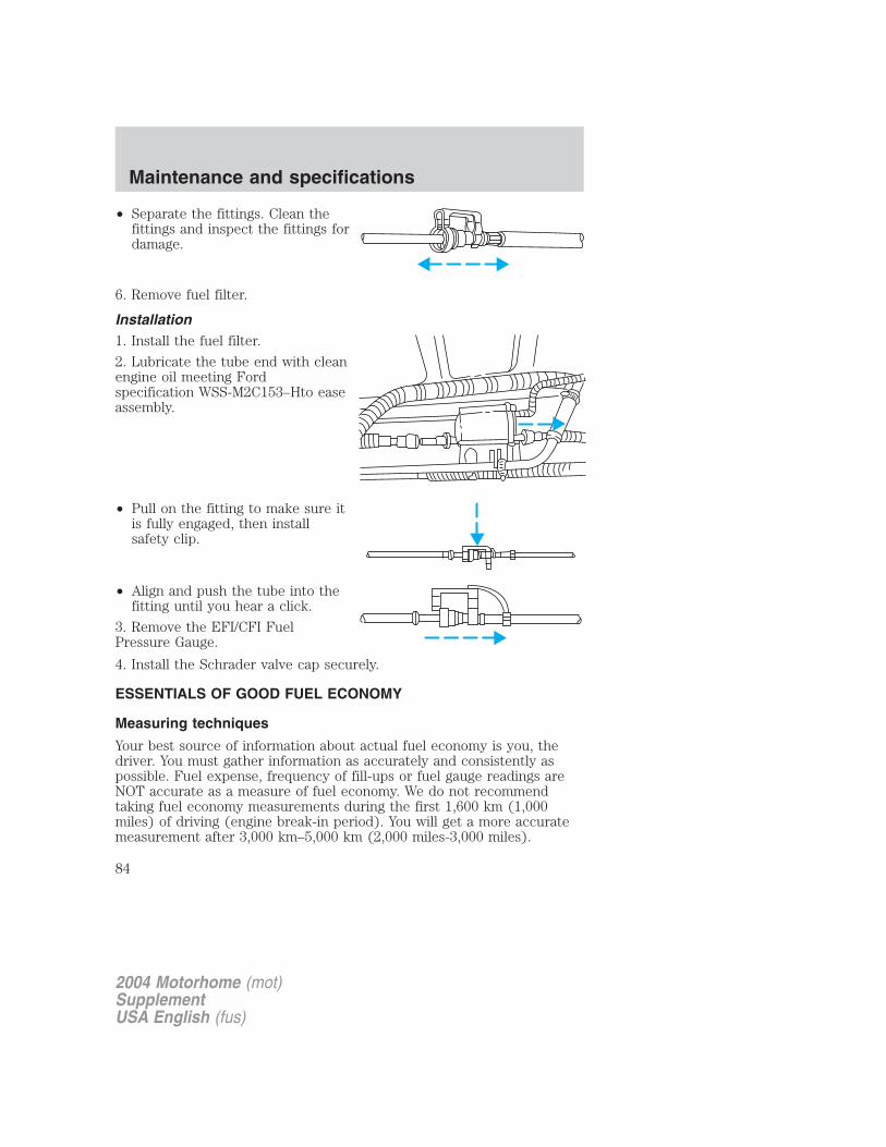
• Separate the fittings. Clean thefittings and inspect the fittings fordamage.
6. Remove fuel filter.
Installation1. Install the fuel filter.
2. Lubricate the tube end with cleanengine oil meeting Fordspecification WSS-M2C153–Hto easeassembly.
• Pull on the fitting to make sure itis fully engaged, then installsafety clip.
• Align and push the tube into thefitting until you hear a click.
3. Remove the EFI/CFI FuelPressure Gauge.
4. Install the Schrader valve cap securely.
ESSENTIALS OF GOOD FUEL ECONOMY
Measuring techniques
Your best source of information about actual fuel economy is you, thedriver. You must gather information as accurately and consistently aspossible. Fuel expense, frequency of fill-ups or fuel gauge readings areNOT accurate as a measure of fuel economy. We do not recommendtaking fuel economy measurements during the first 1,600 km (1,000miles) of driving (engine break-in period). You will get a more accuratemeasurement after 3,000 km–5,000 km (2,000 miles-3,000 miles).
2004 Motorhome (mot)SupplementUSA English (fus)
Maintenance and specifications
84
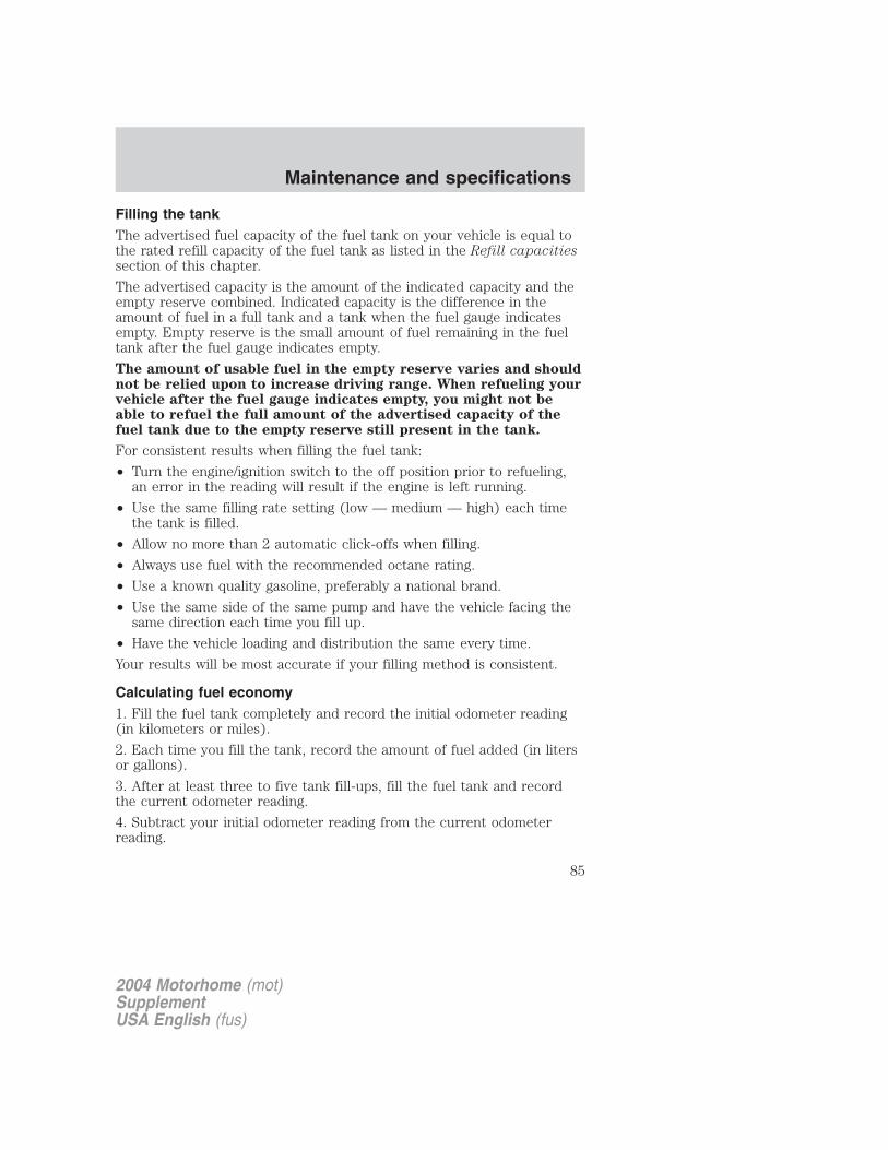
Filling the tankThe advertised fuel capacity of the fuel tank on your vehicle is equal tothe rated refill capacity of the fuel tank as listed in the Refill capacitiessection of this chapter.
The advertised capacity is the amount of the indicated capacity and theempty reserve combined. Indicated capacity is the difference in theamount of fuel in a full tank and a tank when the fuel gauge indicatesempty. Empty reserve is the small amount of fuel remaining in the fueltank after the fuel gauge indicates empty.
The amount of usable fuel in the empty reserve varies and shouldnot be relied upon to increase driving range. When refueling yourvehicle after the fuel gauge indicates empty, you might not beable to refuel the full amount of the advertised capacity of thefuel tank due to the empty reserve still present in the tank.
For consistent results when filling the fuel tank:
• Turn the engine/ignition switch to the off position prior to refueling,an error in the reading will result if the engine is left running.
• Use the same filling rate setting (low — medium — high) each timethe tank is filled.
• Allow no more than 2 automatic click-offs when filling.
• Always use fuel with the recommended octane rating.
• Use a known quality gasoline, preferably a national brand.
• Use the same side of the same pump and have the vehicle facing thesame direction each time you fill up.
• Have the vehicle loading and distribution the same every time.
Your results will be most accurate if your filling method is consistent.
Calculating fuel economy1. Fill the fuel tank completely and record the initial odometer reading(in kilometers or miles).
2. Each time you fill the tank, record the amount of fuel added (in litersor gallons).
3. After at least three to five tank fill-ups, fill the fuel tank and recordthe current odometer reading.
4. Subtract your initial odometer reading from the current odometerreading.
2004 Motorhome (mot)SupplementUSA English (fus)
Maintenance and specifications
85

5. Follow one of the simple calculations in order to determine fueleconomy:
Calculation 1: Multiply liters used by 100, then divide by totalkilometers traveled.
Calculation 2: Divide total miles traveled by total gallons used.
Keep a record for at least one month and record the type of driving (cityor highway). This will provide an accurate estimate of the vehicle’s fueleconomy under current driving conditions. Additionally, keeping recordsduring summer and winter will show how temperature impacts fueleconomy. In general, lower temperatures give lower fuel economy.
Driving style — good driving and fuel economy habitsGive consideration to the lists that follow and you may be able to changea number of variables and improve your fuel economy.
Habits• Smooth, moderate operation can yield up to 10% savings in fuel.
• Steady speeds without stopping will usually give the best fueleconomy.
• Idling for long periods of time (greater than one minute) may wastefuel.
• Anticipate stopping; slowing down may eliminate the need to stop.
• Sudden or hard accelerations may reduce fuel economy.
• Slow down gradually.
• Driving at reasonable speeds (traveling at 88 km/h [55 mph] uses 15%less fuel than traveling at 105 km/h [65 mph]).
• Revving the engine before turning it off may reduce fuel economy.
• Using the air conditioner or defroster may reduce fuel economy.
• You may want to turn off the speed control in hilly terrain ifunnecessary shifting between third and fourth gear occurs.Unnecessary shifting of this type could result in reduced fueleconomy.
• Warming up a vehicle on cold mornings is not required and mayreduce fuel economy.
• Resting your foot on the brake pedal while driving may reduce fueleconomy.
• Combine errands and minimize stop-and-go driving.
2004 Motorhome (mot)SupplementUSA English (fus)
Maintenance and specifications
86

Maintenance• Keep tires properly inflated and use only recommended size.• Operating a vehicle with the wheels out of alignment will reduce fuel
economy.• Use recommended engine oil. Refer to Lubricant specifications in
this chapter.• Perform all regularly scheduled maintenance items. Follow the
recommended maintenance schedule and owner maintenance checksfound in your vehicle scheduled maintenance guide.
Conditions• Heavily loading a vehicle or towing a trailer may reduce fuel economy
at any speed.• Carrying unnecessary weight may reduce fuel economy (approximately
0.4 km/L [1 mpg] is lost for every 180 kg [400 lb] of weight carried).
• Adding certain accessories to your vehicle (for example bugdeflectors, rollbars/light bars, running boards, ski/luggage racks) mayreduce fuel economy.
• Using fuel blended with alcohol may lower fuel economy.
• Fuel economy may decrease with lower temperatures during the first12–16 km (8–10 miles) of driving.
• Driving on flat terrain offers improved fuel economy as compared todriving on hilly terrain.
• Transmissions give their best fuel economy when operated in the topcruise gear and with steady pressure on the gas pedal.
• Close windows for high speed driving.
EPA window stickerEvery new vehicle should have the EPA window sticker. Contact yourdealer if the window sticker is not supplied with your vehicle. The EPAwindow sticker should be your guide for the fuel economy comparisonswith other vehicles.
It is important to note the box in the lower left corner of the windowsticker. These numbers represent the Range of L/100 km (MPG)expected on the vehicle under optimum conditions. Your fuel economymay vary depending upon the method of operation and conditions.
NOTE: Vehicles over 8500 GVW (Gross Vehicle Weight) will not havefuel economy information printed on the EPA window sticker.
2004 Motorhome (mot)SupplementUSA English (fus)
Maintenance and specifications
87
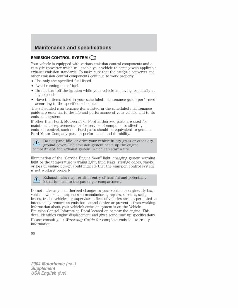
EMISSION CONTROL SYSTEM
Your vehicle is equipped with various emission control components and acatalytic converter which will enable your vehicle to comply with applicableexhaust emission standards. To make sure that the catalytic converter andother emission control components continue to work properly:• Use only the specified fuel listed.• Avoid running out of fuel.• Do not turn off the ignition while your vehicle is moving, especially at
high speeds.• Have the items listed in your scheduled maintenance guide performed
according to the specified schedule.The scheduled maintenance items listed in the scheduled maintenanceguide are essential to the life and performance of your vehicle and to itsemissions system.If other than Ford, Motorcraft or Ford-authorized parts are used formaintenance replacements or for service of components affectingemission control, such non-Ford parts should be equivalent to genuineFord Motor Company parts in performance and durability.
Do not park, idle, or drive your vehicle in dry grass or other dryground cover. The emission system heats up the engine
compartment and exhaust system, which can start a fire.
Illumination of the “Service Engine Soon” light, charging system warninglight or the temperature warning light, fluid leaks, strange odors, smokeor loss of engine power, could indicate that the emission control systemis not working properly.
Exhaust leaks may result in entry of harmful and potentiallylethal fumes into the passenger compartment.
Do not make any unauthorized changes to your vehicle or engine. By law,vehicle owners and anyone who manufactures, repairs, services, sells,leases, trades vehicles, or supervises a fleet of vehicles are not permitted tointentionally remove an emission control device or prevent it from working.Information about your vehicle’s emission system is on the VehicleEmission Control Information Decal located on or near the engine. Thisdecal identifies engine displacement and gives some tune up specifications.Please consult your Warranty Guide for complete emission warrantyinformation.
2004 Motorhome (mot)SupplementUSA English (fus)
Maintenance and specifications
88
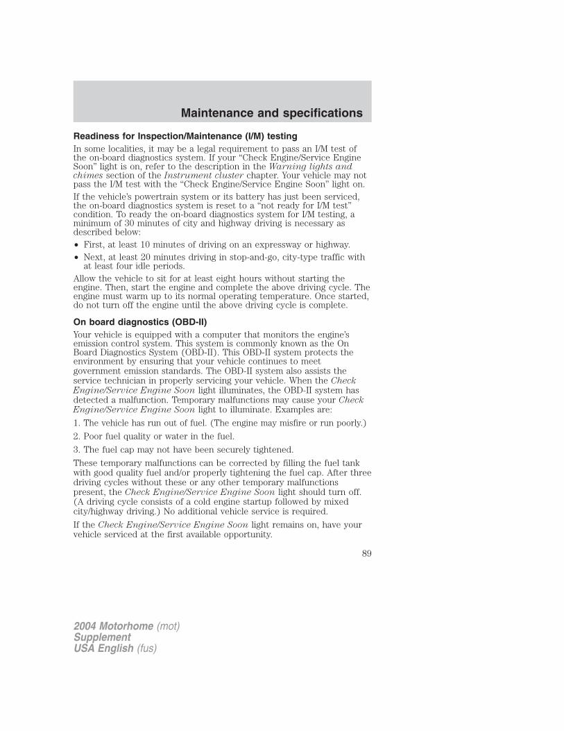
Readiness for Inspection/Maintenance (I/M) testingIn some localities, it may be a legal requirement to pass an I/M test ofthe on-board diagnostics system. If your “Check Engine/Service EngineSoon” light is on, refer to the description in the Warning lights andchimes section of the Instrument cluster chapter. Your vehicle may notpass the I/M test with the “Check Engine/Service Engine Soon” light on.If the vehicle’s powertrain system or its battery has just been serviced,the on-board diagnostics system is reset to a “not ready for I/M test”condition. To ready the on-board diagnostics system for I/M testing, aminimum of 30 minutes of city and highway driving is necessary asdescribed below:• First, at least 10 minutes of driving on an expressway or highway.• Next, at least 20 minutes driving in stop-and-go, city-type traffic with
at least four idle periods.Allow the vehicle to sit for at least eight hours without starting theengine. Then, start the engine and complete the above driving cycle. Theengine must warm up to its normal operating temperature. Once started,do not turn off the engine until the above driving cycle is complete.
On board diagnostics (OBD-II)Your vehicle is equipped with a computer that monitors the engine’semission control system. This system is commonly known as the OnBoard Diagnostics System (OBD-II). This OBD-II system protects theenvironment by ensuring that your vehicle continues to meetgovernment emission standards. The OBD-II system also assists theservice technician in properly servicing your vehicle. When the CheckEngine/Service Engine Soon light illuminates, the OBD-II system hasdetected a malfunction. Temporary malfunctions may cause your CheckEngine/Service Engine Soon light to illuminate. Examples are:
1. The vehicle has run out of fuel. (The engine may misfire or run poorly.)
2. Poor fuel quality or water in the fuel.
3. The fuel cap may not have been securely tightened.
These temporary malfunctions can be corrected by filling the fuel tankwith good quality fuel and/or properly tightening the fuel cap. After threedriving cycles without these or any other temporary malfunctionspresent, the Check Engine/Service Engine Soon light should turn off.(A driving cycle consists of a cold engine startup followed by mixedcity/highway driving.) No additional vehicle service is required.
If the Check Engine/Service Engine Soon light remains on, have yourvehicle serviced at the first available opportunity.
2004 Motorhome (mot)SupplementUSA English (fus)
Maintenance and specifications
89
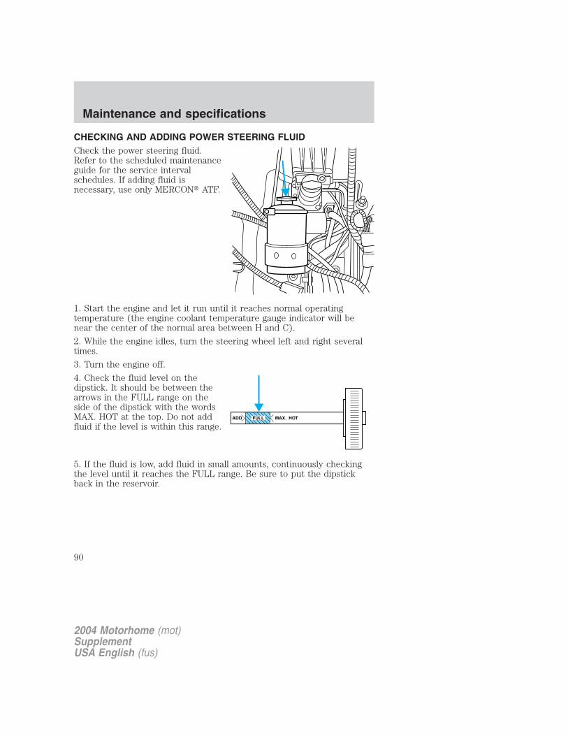
CHECKING AND ADDING POWER STEERING FLUIDCheck the power steering fluid.Refer to the scheduled maintenanceguide for the service intervalschedules. If adding fluid isnecessary, use only MERCON� ATF.
1. Start the engine and let it run until it reaches normal operatingtemperature (the engine coolant temperature gauge indicator will benear the center of the normal area between H and C).
2. While the engine idles, turn the steering wheel left and right severaltimes.
3. Turn the engine off.
4. Check the fluid level on thedipstick. It should be between thearrows in the FULL range on theside of the dipstick with the wordsMAX. HOT at the top. Do not addfluid if the level is within this range.
5. If the fluid is low, add fluid in small amounts, continuously checkingthe level until it reaches the FULL range. Be sure to put the dipstickback in the reservoir.
ADD MAX. HOTFULL
2004 Motorhome (mot)SupplementUSA English (fus)
Maintenance and specifications
90
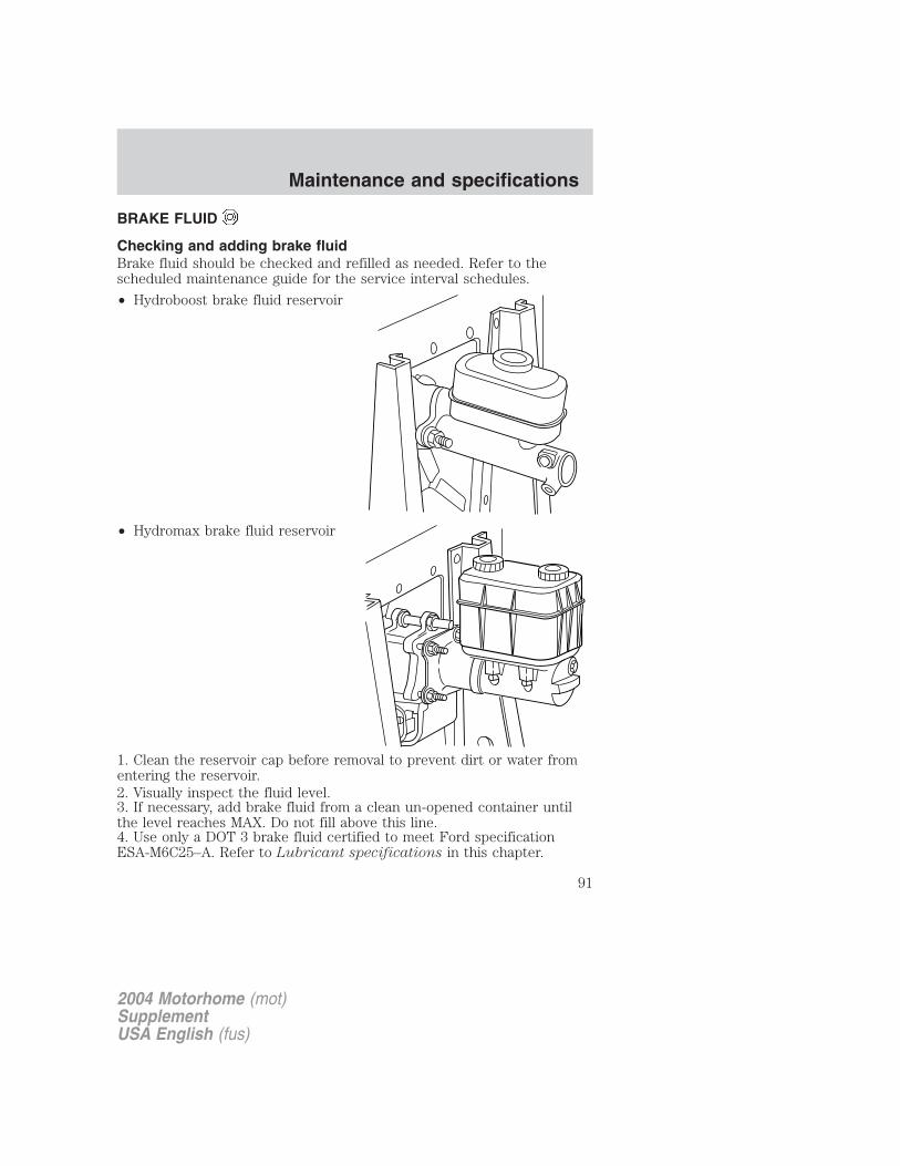
BRAKE FLUID
Checking and adding brake fluidBrake fluid should be checked and refilled as needed. Refer to thescheduled maintenance guide for the service interval schedules.
• Hydroboost brake fluid reservoir
• Hydromax brake fluid reservoir
1. Clean the reservoir cap before removal to prevent dirt or water fromentering the reservoir.2. Visually inspect the fluid level.3. If necessary, add brake fluid from a clean un-opened container untilthe level reaches MAX. Do not fill above this line.4. Use only a DOT 3 brake fluid certified to meet Ford specificationESA-M6C25–A. Refer to Lubricant specifications in this chapter.
2004 Motorhome (mot)SupplementUSA English (fus)
Maintenance and specifications
91
Brake fluid is toxic. If brake fluid contacts the eyes, flush eyeswith running water for 15 minutes. Seek medical attention if
irritation persists. If taken internally, drink water and induce vomiting.Seek medical attention immediately.
If you use a brake fluid that is not DOT 3, you will causepermanent damage to your brakes.
Do not let the reservoir for the master cylinder run dry. Thismay cause the brakes to fail.
Brake system fluid should be replaced on a regular basis to maintainoptimum braking performance, especially under heavy-duty drivingconditions such as frequent steep grades or heavy towing loads. Refer tothe scheduled maintenance guide for the service interval schedules.
TRANSMISSION FLUID
Checking automatic transmission fluidRefer to your scheduled maintenance guide for scheduled intervals forfluid checks and changes. Your transmission does not consume fluid.However, the fluid level should be checked if the transmission is notworking properly, i.e., if the transmission slips or shifts slowly or if younotice some sign of fluid leakage.
Automatic transmission fluid expands when warmed. To obtain anaccurate fluid check, drive the vehicle until it is at normal operatingtemperature (approximately 30 km [20 miles]). If your vehicle has beenoperated for an extended period at high speeds, in city traffic during hotweather or pulling a trailer, the vehicle should be turned off for about 30minutes to allow fluid to cool to normal operating temperature 66°C -77°C (150°F - 170°F) before checking.
1. Drive the vehicle 30 km (20 miles) or until it reaches normal operatingtemperature.
2. Park the vehicle on a level surface and engage the parking brake.
3. With the parking brake engaged and your foot on the brake pedal,start the engine and move the gearshift lever through all of the gearranges. Allow sufficient time for each gear to engage.
4. Latch the gearshift lever in P (Park) and leave the engine running.
2004 Motorhome (mot)SupplementUSA English (fus)
Maintenance and specifications
92

5. Remove the dipstick, wiping it clean with a clean, dry lint free rag. Ifnecessary, refer to Identifying components in the engine compartment
in this chapter for the location of the dipstick.
6. Install the dipstick making sure it is fully seated in the filler tube.
7. Remove the dipstick and inspect the fluid level. The fluid should be inthe designated area for normal operating temperature or ambienttemperature.
Low fluid levelDo not drive the vehicle if the fluidlevel is at the bottom of the dipstickand the ambient temperature isabove 10°C (50°F).
Correct fluid level
The transmission fluid should be checked at normal operatingtemperature 66°C-77°C (150°F-170°F) on a level surface. The normaloperating temperature can be reached after approximately 30 km (20miles) of driving.
You can check the fluid without driving if the ambient temperature isabove 10°C (50°F). However, if fluid is added at this time, an overfillcondition could result when the vehicle reaches normal operatingtemperature.
The transmission fluid should be inthis range if at normal operatingtemperature (66°C-77°C[150°F-170°F]).
The transmission fluid should be inthis range if at ambient temperature(10°C-35°C [50°F-95°F]).
High fluid levelFluid levels above the safe rangemay result in transmission failure.An overfill condition of transmissionfluid may cause shift and/orengagement concerns and/or possible damage.
High fluid levels can be caused by an overheating condition.
2004 Motorhome (mot)SupplementUSA English (fus)
Maintenance and specifications
93

Adjusting automatic transmission fluid levelsBefore adding any fluid, make sure the correct type is used. The type offluid used is normally indicated on the dipstick and also in theLubricant specifications section in this chapter.
Use of a non-approved automatic transmission fluid may causeinternal transmission component damage.
If necessary, add fluid in 250 ml (1/2 pint) increments through the fillertube until the level is correct.
If an overfill occurs, excess fluidshould be removed by a qualifiedtechnician.
An overfill condition of transmission fluid may cause shift and/orengagement concerns and/or possible damage.
Do not use supplemental transmission fluid additives, treatments orcleaning agents. The use of these materials may affect transmissionoperation and result in damage to internal transmission components.
DRIVELINE UNIVERSAL JOINT AND SLIP YOKEIf the original universal joints are equipped with grease fittings.Lubrication will be necessary. Refer to the scheduled maintenance guidefor maintenance intervals.
STEERING LINKAGE LUBRICATION POINTS
2004 Motorhome (mot)SupplementUSA English (fus)
Maintenance and specifications
94
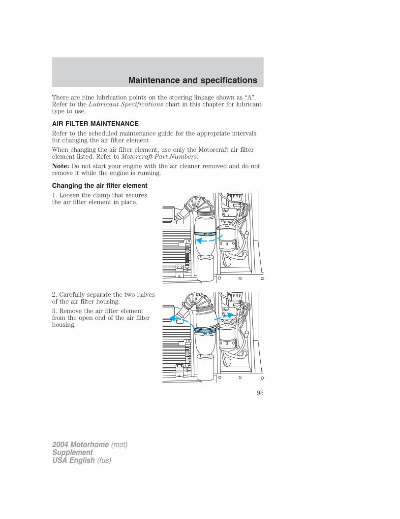
There are nine lubrication points on the steering linkage shown as “A”.Refer to the Lubricant Specifications chart in this chapter for lubricanttype to use.
AIR FILTER MAINTENANCERefer to the scheduled maintenance guide for the appropriate intervalsfor changing the air filter element.
When changing the air filter element, use only the Motorcraft air filterelement listed. Refer to Motorcraft Part Numbers.
Note: Do not start your engine with the air cleaner removed and do notremove it while the engine is running.
Changing the air filter element1. Loosen the clamp that securesthe air filter element in place.
2. Carefully separate the two halvesof the air filter housing.
3. Remove the air filter elementfrom the open end of the air filterhousing.
2004 Motorhome (mot)SupplementUSA English (fus)
Maintenance and specifications
95
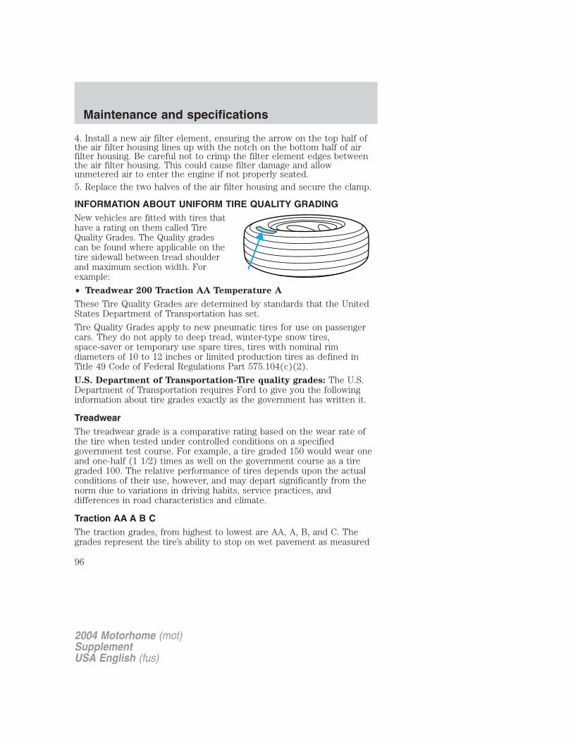
4. Install a new air filter element, ensuring the arrow on the top half ofthe air filter housing lines up with the notch on the bottom half of airfilter housing. Be careful not to crimp the filter element edges betweenthe air filter housing. This could cause filter damage and allowunmetered air to enter the engine if not properly seated.5. Replace the two halves of the air filter housing and secure the clamp.
INFORMATION ABOUT UNIFORM TIRE QUALITY GRADINGNew vehicles are fitted with tires thathave a rating on them called TireQuality Grades. The Quality gradescan be found where applicable on thetire sidewall between tread shoulderand maximum section width. Forexample:
• Treadwear 200 Traction AA Temperature A
These Tire Quality Grades are determined by standards that the UnitedStates Department of Transportation has set.
Tire Quality Grades apply to new pneumatic tires for use on passengercars. They do not apply to deep tread, winter-type snow tires,space-saver or temporary use spare tires, tires with nominal rimdiameters of 10 to 12 inches or limited production tires as defined inTitle 49 Code of Federal Regulations Part 575.104(c)(2).
U.S. Department of Transportation-Tire quality grades: The U.S.Department of Transportation requires Ford to give you the followinginformation about tire grades exactly as the government has written it.
TreadwearThe treadwear grade is a comparative rating based on the wear rate ofthe tire when tested under controlled conditions on a specifiedgovernment test course. For example, a tire graded 150 would wear oneand one-half (1 1/2) times as well on the government course as a tiregraded 100. The relative performance of tires depends upon the actualconditions of their use, however, and may depart significantly from thenorm due to variations in driving habits, service practices, anddifferences in road characteristics and climate.
Traction AA A B CThe traction grades, from highest to lowest are AA, A, B, and C. Thegrades represent the tire’s ability to stop on wet pavement as measured
2004 Motorhome (mot)SupplementUSA English (fus)
Maintenance and specifications
96
under controlled conditions on specified government test surfaces ofasphalt and concrete. A tire marked C may have poor tractionperformance.
The traction grade assigned to this tire is based onstraight-ahead braking traction tests, and does not include
acceleration, cornering, hydroplaning or peak traction characteristics.
Temperature A B CThe temperature grades are A (the highest), B and C, representing thetire’s resistance to the generation of heat and its ability to dissipate heatwhen tested under controlled conditions on a specified indoor laboratorytest wheel. Sustained high temperature can cause the material of the tireto degenerate and reduce tire life, and excessive temperature can lead tosudden tire failure. The grade C corresponds to a level of performancewhich all passenger car tires must meet under the Federal Motor VehicleSafety Standard No. 109. Grades B and A represent higher levels ofperformance on the laboratory test wheel than the minimum required bylaw.
The temperature grade for this tire is established for a tire thatis properly inflated and not overloaded. Excessive speed,
underinflation, or excessive loading, either separately or incombination, can cause heat buildup and possible tire failure.
TIRESTires are designed to give many thousands of miles of service, but theymust be maintained in order to get the maximum benefit from them.
Glossary of tire terminology• Tire label: A label showing the OE (Original Equipment) tire sizes,
recommended inflation pressure and the maximum weight the vehiclecan carry.
• Tire Identification Number (TIN): A number on the sidewall ofeach tire providing information about the tire brand andmanufacturing plant, tire size and date of manufacturer.
• Inflation pressure: A measure of the amount of air in a tire.
• Standard load: A class of P-metric or Metric tires designed to carry amaximum load at 35 psi [37 psi (2.5 bar) for Metric tires]. Increasingthe inflation pressure beyond this pressure will not increase the tiresload carrying capability.
2004 Motorhome (mot)SupplementUSA English (fus)
Maintenance and specifications
97
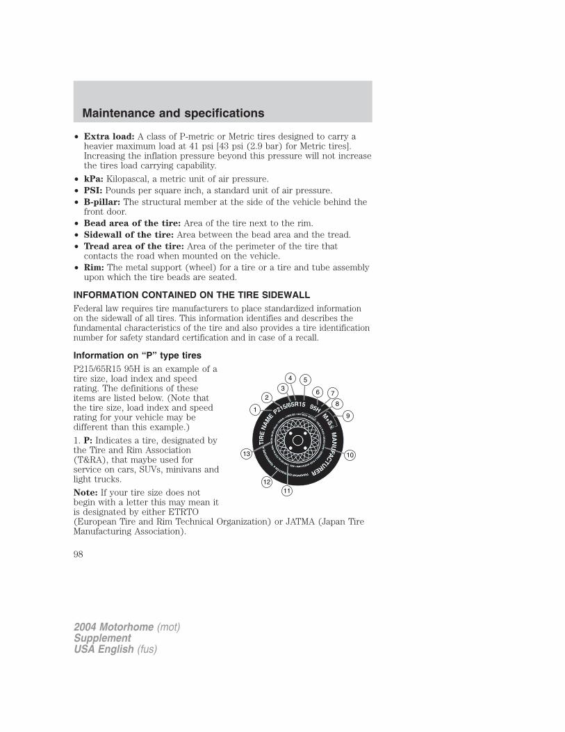
• Extra load: A class of P-metric or Metric tires designed to carry aheavier maximum load at 41 psi [43 psi (2.9 bar) for Metric tires].Increasing the inflation pressure beyond this pressure will not increasethe tires load carrying capability.
• kPa: Kilopascal, a metric unit of air pressure.• PSI: Pounds per square inch, a standard unit of air pressure.• B-pillar: The structural member at the side of the vehicle behind the
front door.• Bead area of the tire: Area of the tire next to the rim.• Sidewall of the tire: Area between the bead area and the tread.• Tread area of the tire: Area of the perimeter of the tire that
contacts the road when mounted on the vehicle.• Rim: The metal support (wheel) for a tire or a tire and tube assembly
upon which the tire beads are seated.
INFORMATION CONTAINED ON THE TIRE SIDEWALLFederal law requires tire manufacturers to place standardized informationon the sidewall of all tires. This information identifies and describes thefundamental characteristics of the tire and also provides a tire identificationnumber for safety standard certification and in case of a recall.
Information on “P” type tiresP215/65R15 95H is an example of atire size, load index and speedrating. The definitions of theseitems are listed below. (Note thatthe tire size, load index and speedrating for your vehicle may bedifferent than this example.)
1. P: Indicates a tire, designated bythe Tire and Rim Association(T&RA), that maybe used forservice on cars, SUVs, minivans andlight trucks.
Note: If your tire size does notbegin with a letter this may mean itis designated by either ETRTO(European Tire and Rim Technical Organization) or JATMA (Japan TireManufacturing Association).
2004 Motorhome (mot)SupplementUSA English (fus)
Maintenance and specifications
98
2. 215: Indicates the nominal width of the tire in millimeters fromsidewall edge to sidewall edge. In general, the larger the number, thewider the tire.
3. 65: Indicates the aspect ratio which gives the tire’s ratio of height towidth.
4. R: Indicates a “radial” type tire.
5. 15: Indicates the wheel or rim diameter in inches. If you change yourwheel size, you will have to purchase new tires to match the new wheeldiameter.
6. 95: Indicates the tire’s load index. It is an index that relates to howmuch weight a tire can carry. You may find this information in yourowner’s guide. If not, contact a local tire dealer.
Note: You may not find this information on all tires because it is notrequired by federal law.7. H: Indicates the tire’s speed rating. The speed rating denotes thespeed at which a tire is designed to be driven for extended periods oftime under a standard condition of load and inflation pressure. The tireson your vehicle may operate at different conditions for load and inflationpressure. These speed ratings may need to be adjusted for the differencein conditions. The ratings range from 159 km/h (99 mph) to 299 km/h(186 mph). These ratings are listed in the following chart.Note: You may not find this information on all tires because it is notrequired by federal law.
Letter rating Speed rating - km/h (mph)
Q 159 km/h (99 mph)R 171 km/h (106 mph)S 180 km/h (112 mph)T 190 km/h (118 mph)U 200 km/h (124 mph)H 210 km/h (130 mph)V 240 km/h (149 mph)W 270 km/h (168 mph)Y 299 km/h (186 mph)
Note: For tires with a maximum speed capability over 240 km/h (149mph), tire manufacturers sometimes use the letters ZR. For those witha maximum speed capability over 299 km/h (186 mph), tire letters ZR.
2004 Motorhome (mot)SupplementUSA English (fus)
Maintenance and specifications
99
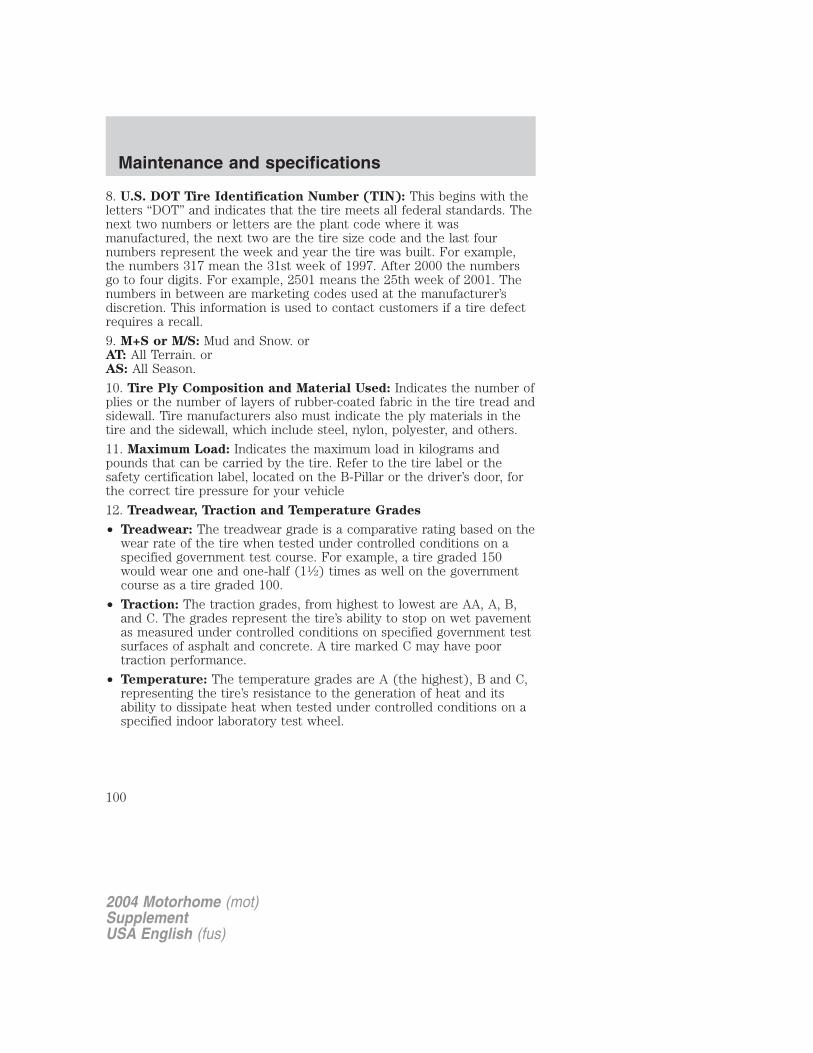
8. U.S. DOT Tire Identification Number (TIN): This begins with theletters “DOT” and indicates that the tire meets all federal standards. Thenext two numbers or letters are the plant code where it wasmanufactured, the next two are the tire size code and the last fournumbers represent the week and year the tire was built. For example,the numbers 317 mean the 31st week of 1997. After 2000 the numbersgo to four digits. For example, 2501 means the 25th week of 2001. Thenumbers in between are marketing codes used at the manufacturer’sdiscretion. This information is used to contact customers if a tire defectrequires a recall.
9. M+S or M/S: Mud and Snow. orAT: All Terrain. orAS: All Season.
10. Tire Ply Composition and Material Used: Indicates the number ofplies or the number of layers of rubber-coated fabric in the tire tread andsidewall. Tire manufacturers also must indicate the ply materials in thetire and the sidewall, which include steel, nylon, polyester, and others.
11. Maximum Load: Indicates the maximum load in kilograms andpounds that can be carried by the tire. Refer to the tire label or thesafety certification label, located on the B-Pillar or the driver’s door, forthe correct tire pressure for your vehicle
12. Treadwear, Traction and Temperature Grades
• Treadwear: The treadwear grade is a comparative rating based on thewear rate of the tire when tested under controlled conditions on aspecified government test course. For example, a tire graded 150would wear one and one-half (11⁄2) times as well on the governmentcourse as a tire graded 100.
• Traction: The traction grades, from highest to lowest are AA, A, B,and C. The grades represent the tire’s ability to stop on wet pavementas measured under controlled conditions on specified government testsurfaces of asphalt and concrete. A tire marked C may have poortraction performance.
• Temperature: The temperature grades are A (the highest), B and C,representing the tire’s resistance to the generation of heat and itsability to dissipate heat when tested under controlled conditions on aspecified indoor laboratory test wheel.
2004 Motorhome (mot)SupplementUSA English (fus)
Maintenance and specifications
100
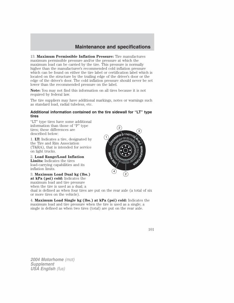
13. Maximum Permissible Inflation Pressure: Tire manufacturesmaximum permissible pressure and/or the pressure at which themaximum load can be carried by the tire. This pressure is normallyhigher than the manufacturer’s recommended cold inflation pressurewhich can be found on either the tire label or certification label which islocated on the structure by the trailing edge of the driver’s door or theedge of the driver’s door. The cold inflation pressure should never be setlower than the recommended pressure on the label.
Note: You may not find this information on all tires because it is notrequired by federal law.
The tire suppliers may have additional markings, notes or warnings suchas standard load, radial tubeless, etc.
Additional information contained on the tire sidewall for “LT” typetires“LT” type tires have some additionalinformation than those of “P” typetires; these differences aredescribed below:
1. LT: Indicates a tire, designated bythe Tire and Rim Association(T&RA), that is intended for serviceon light trucks.
2. Load Range/Load InflationLimits: Indicates the tiresload-carrying capabilities and itsinflation limits.
3. Maximum Load Dual kg (lbs.)at kPa (psi) cold: Indicates themaximum load and tire pressurewhen the tire is used as a dual; adual is defined as when four tires are put on the rear axle (a total of sixor more tires on the vehicle).
4. Maximum Load Single kg (lbs.) at kPa (psi) cold: Indicates themaximum load and tire pressure when the tire is used as a single; asingle is defined as when two tires (total) are put on the rear axle.
2004 Motorhome (mot)SupplementUSA English (fus)
Maintenance and specifications
101

Information on “T” type tiresT145/80D16 is an example of a tiresize.
Note: The temporary tire size foryour vehicle may be different thanthis example.
1. T: Indicates a type of tire,designated by the Tire and RimAssociation (T&RA), that isintended for temporary service oncars, SUVs, minivans and lighttrucks.
2. 145: Indicates the nominal widthof the tire in millimeters fromsidewall edge to sidewall edge. Ingeneral, the larger the number, thewider the tire.
3. 80: Indicates the aspect ratiowhich gives the tires ratio of height to width. Numbers of 70 or lowerindicate a short sidewall.
4. D: Indicates a “diagonal” type tire.R: Indicates a “radial” type tire.
5. 16: Indicates the wheel or rim diameter in inches. If you change yourwheel size, you will have to purchase new tires to match the new wheeldiameter.
Location of the tire labelYou will find a tire label containing tire inflation pressure by tire size andother important information located on the B-Pillar or the driver’s door.
TIRE CAREImproper or inadequate vehicle maintenance can also cause tires to wearabnormally. Here are some of the important maintenance items
SPARE TIRE
TEMPORARYUSEONLYINFLATETO60P.S.I.T
T145/80D16 105M
2004 Motorhome (mot)SupplementUSA English (fus)
Maintenance and specifications
102
Tire inflation pressureUse a tire gauge to check the tire inflation pressure at least monthly(check the tire inflation pressure in the spare tire every 6 months) andbefore long trips. You are strongly urged to buy a reliable tire pressuregauge, as automatic service station gauges may be inaccurate. Fordrecommends the use of a digital or dial type tire pressure gauge ratherthan a stick type of tire pressure gauge.Use the recommended cold inflation pressure for optimum tireperformance and wear. Under-inflation or over-inflation may causeuneven treadwear patterns.
Under-inflation is the most common cause of tire failures andmay result in severe tire cracking, tread separation or �blowout�,
with unexpected loss of vehicle control and increased risk of injury.Under-inflation increases sidewall flexing and rolling resistance,resulting in heat buildup and internal damage to the tire. It also mayresult in unnecessary tire stress, irregular wear, loss of vehicle controland accidents. A tire can lose up to half of its air pressure and notappear to be flat!
When weather temperature changes occur, tire inflation pressures alsochange. A 10 degree temperature change causes a corresponding drop of7 kPa (1 psi) in inflation pressure. Check your tire pressures frequentlyand adjust them to the proper pressure which can be found on the tirelabel or certification label.
If checking tire pressure when the tire is hot, (i.e. driven more than 1.6km [1mile]), never “bleed” or reduce air pressure. The tires are hot fromdriving and it is normal for pressures to increase above recommendedcold pressures. A hot tire at or below recommended cold inflationpressure could be significantly under-inflated.
To check the pressure in your tire(s):
1. Make sure the tires are cool, meaning they are not hot from drivingeven a mile.
Note: If you have to drive a distance to get air for your tire(s), checkand record the tire pressure first and add the appropriate air pressurewhen you get to the pump. It is normal for tires to heat up and the airpressure inside to go up as you drive. Never “bleed” or reduce airpressure when tires are hot.
2. Remove the cap from the valve on one tire, then firmly press the tiregauge onto the valve.
2004 Motorhome (mot)SupplementUSA English (fus)
Maintenance and specifications
103
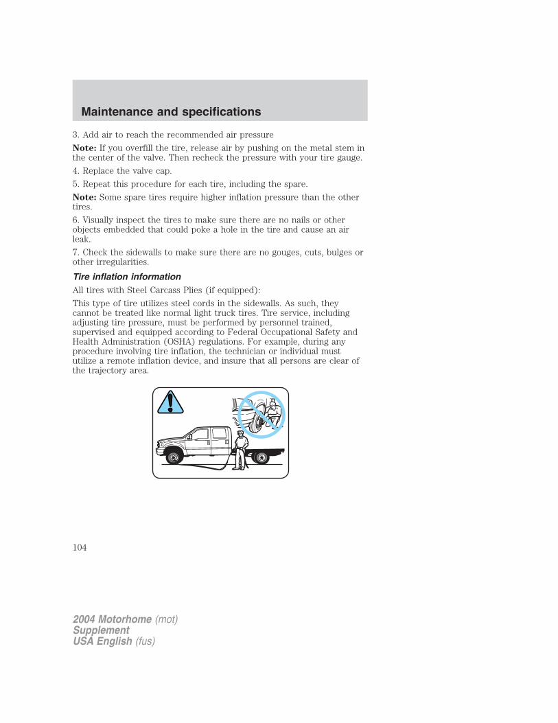
3. Add air to reach the recommended air pressure
Note: If you overfill the tire, release air by pushing on the metal stem inthe center of the valve. Then recheck the pressure with your tire gauge.
4. Replace the valve cap.
5. Repeat this procedure for each tire, including the spare.
Note: Some spare tires require higher inflation pressure than the othertires.
6. Visually inspect the tires to make sure there are no nails or otherobjects embedded that could poke a hole in the tire and cause an airleak.
7. Check the sidewalls to make sure there are no gouges, cuts, bulges orother irregularities.
Tire inflation informationAll tires with Steel Carcass Plies (if equipped):
This type of tire utilizes steel cords in the sidewalls. As such, theycannot be treated like normal light truck tires. Tire service, includingadjusting tire pressure, must be performed by personnel trained,supervised and equipped according to Federal Occupational Safety andHealth Administration (OSHA) regulations. For example, during anyprocedure involving tire inflation, the technician or individual mustutilize a remote inflation device, and insure that all persons are clear ofthe trajectory area.
2004 Motorhome (mot)SupplementUSA English (fus)
Maintenance and specifications
104
WARNING An inflated tire and rim can be very dangerous ifimproperly used, serviced or maintained. To avoid serious injury,
never attempt to re-inflate a tire which has been run flat or seriouslyunder-inflated without first removing the tire from the wheel assemblyfor inspection. Do not attempt to add air to tires or replace tires orwheels without first taking precautions to protect persons andproperty.
Tire and wheel alignment
A bad jolt from hitting a curb or pothole can cause the front end of yourvehicle to become misaligned or damage to your tires. If your vehicleseems to pull to one side, vibrate or shake when you’re driving, thewheels may be out of alignment. Have a qualified technician at areputable repair facility check the wheel alignment periodically.
Wheel misalignment in the front or the rear can cause uneven and rapidtreadwear of your tires and should be corrected by a qualified technicianat a reputable repair facility. Front wheel drive (FWD) vehicles, andthose with independent front suspension require alignment of all fourwheels.
The tires should also be balanced periodically. An unbalanced tire andwheel assembly may result in irregular tire wear.
Tire rotation
Rotating your tires at the recommended interval (as indicated in theService Maintenance Guide that comes with your vehicle) will help yourtires wear more evenly providing better tire performance and longer tirelife. Unless otherwise specified, rotate the tires approximately every8,000 km (5,000 miles).
2004 Motorhome (mot)SupplementUSA English (fus)
Maintenance and specifications
105

• Front Wheel Drive (FWD)vehicles (front tires at top ofdiagram)
• Rear Wheel Drive (RWD)vehicles/Four Wheel Drive (4WD)vehicles (front tires at top ofdiagram)
2004 Motorhome (mot)SupplementUSA English (fus)
Maintenance and specifications
106
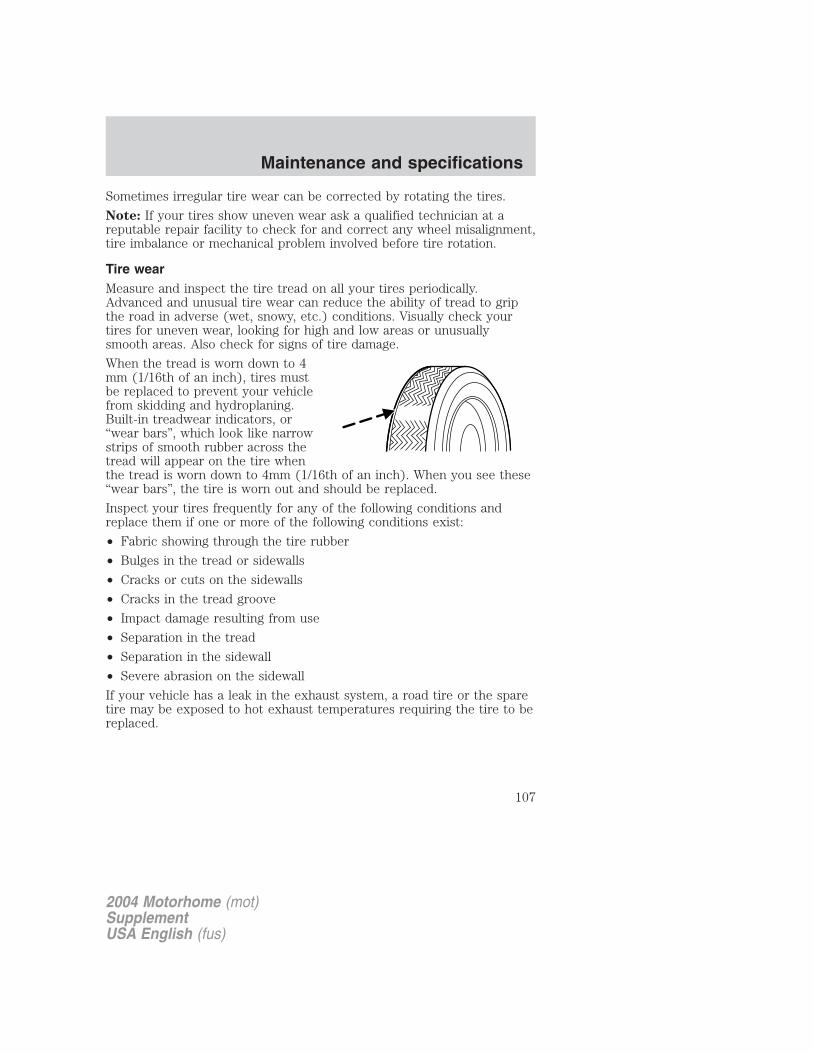
Sometimes irregular tire wear can be corrected by rotating the tires.
Note: If your tires show uneven wear ask a qualified technician at areputable repair facility to check for and correct any wheel misalignment,tire imbalance or mechanical problem involved before tire rotation.
Tire wearMeasure and inspect the tire tread on all your tires periodically.Advanced and unusual tire wear can reduce the ability of tread to gripthe road in adverse (wet, snowy, etc.) conditions. Visually check yourtires for uneven wear, looking for high and low areas or unusuallysmooth areas. Also check for signs of tire damage.
When the tread is worn down to 4mm (1/16th of an inch), tires mustbe replaced to prevent your vehiclefrom skidding and hydroplaning.Built-in treadwear indicators, or“wear bars”, which look like narrowstrips of smooth rubber across thetread will appear on the tire whenthe tread is worn down to 4mm (1/16th of an inch). When you see these“wear bars”, the tire is worn out and should be replaced.
Inspect your tires frequently for any of the following conditions andreplace them if one or more of the following conditions exist:
• Fabric showing through the tire rubber
• Bulges in the tread or sidewalls
• Cracks or cuts on the sidewalls
• Cracks in the tread groove
• Impact damage resulting from use
• Separation in the tread
• Separation in the sidewall
• Severe abrasion on the sidewall
If your vehicle has a leak in the exhaust system, a road tire or the sparetire may be exposed to hot exhaust temperatures requiring the tire to bereplaced.
2004 Motorhome (mot)SupplementUSA English (fus)
Maintenance and specifications
107

Safety practicesDriving habits have a great deal to do with your tire mileage and safety.• Observe posted speed limits• Avoid fast starts, stops and turns• Avoid potholes and objects on the road• Do not run over curbs or hit the tire against a curb when parkingIf you vehicle is stuck in snow, mud, sand, etc., do not rapidly spin thetires; spinning the tires can tear the tire and cause an explosion. A tirecan explode in as little as three to five seconds.
Tire explosions can cause death, personal injury or propertydamage. Do not allow anyone to stand near, or directly ahead or
behind the spinning tire.
Never spin the tires in excess of the 55 km/h (35 mph) pointindicated on the speedometer.
Highway hazardsNo matter how carefully you drive there’s always the possibility that youmay eventually have a flat tire on the highway. Drive slowly to theclosest safe area out of traffic. This may further damage the flat tire, butyour safety is more important.If you feel a sudden vibration or ride disturbance while driving or yoususpect your tire or vehicle has been damaged, immediately reduce yourspeed. Drive with caution until you can safely pull off the road. Stop andinspect the tire for damage. If the tire is under-inflated or damaged,deflate it, remove wheel and replace it with your spare tire and wheel. Ifyou cannot detect a cause, have the vehicle towed to the nearest repairfacility or tire dealer to have the vehicle inspected.
SNOW TIRES AND CHAINS
Snow tires must be the same size and grade as the tires youcurrently have on your vehicle.
The tires on your vehicle have all weather treads to provide traction inrain and snow. However, in some climates, you may need to use snowtires and chains. If you need to use chains, it is recommended that steelwheels (of the same size and specifications) be used, as chains may chipaluminum wheels.
2004 Motorhome (mot)SupplementUSA English (fus)
Maintenance and specifications
108
Follow these guidelines when using snow tires and chains:
• Use only SAE Class S chains.
• Install chains securely, verifying that the chains do not touch anywiring, brake lines or fuel lines.
• Drive cautiously. If you hear the chains rub or bang against yourvehicle, stop and re-tighten the chains. If this does not work, removethe chains to prevent damage to your vehicle.
• If possible, avoid fully loading your vehicle.
• Remove the tire chains when they are no longer needed. Do not usetire chains on dry roads.
• The suspension insulation and bumpers will help prevent vehicledamage. Do not remove these components from your vehicle whenusing snow tires and chains.
MOTORCRAFT PART NUMBERS
Component 6.8L V10 engine
Air filter element FA-1634Battery BXT-65-750Fuel filter FG-872Oil filter FL-820-SPCV valve EV-270Spark plugs* AGSF-22W
*Refer to Vehicle Emissions Control Information (VECI) decal for sparkplug gap information.
2004 Motorhome (mot)SupplementUSA English (fus)
Maintenance and specifications
109
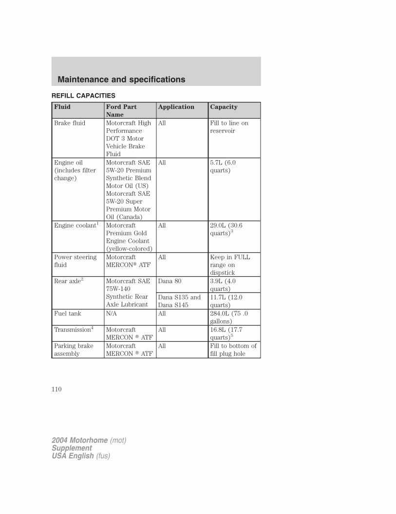
REFILL CAPACITIES
Fluid Ford Part
Name
Application Capacity
Brake fluid Motorcraft HighPerformanceDOT 3 MotorVehicle BrakeFluid
All Fill to line onreservoir
Engine oil(includes filterchange)
Motorcraft SAE5W-20 PremiumSynthetic BlendMotor Oil (US)Motorcraft SAE5W-20 SuperPremium MotorOil (Canada)
All 5.7L (6.0quarts)
Engine coolant1 MotorcraftPremium GoldEngine Coolant(yellow-colored)
All 29.0L (30.6quarts)3
Power steeringfluid
MotorcraftMERCON� ATF
All Keep in FULLrange ondispstick
Rear axle2 Motorcraft SAE75W-140Synthetic RearAxle Lubricant
Dana 80 3.9L (4.0quarts)
Dana S135 andDana S145
11.7L (12.0quarts)
Fuel tank N/A All 284.0L (75 .0gallons)
Transmission4 MotorcraftMERCON � ATF
All 16.8L (17.7quarts)5
Parking brakeassembly
MotorcraftMERCON � ATF
All Fill to bottom offill plug hole
2004 Motorhome (mot)SupplementUSA English (fus)
Maintenance and specifications
110
1Add the coolant type originally equipped in your vehicle.2Fill 6 mm to 14 mm (1/4 inch to 9/16 inch) below bottom of fill hole.
Your vehicle’s rear axle is filled with a synthetic rear axle lubricant and isconsidered lubricated for life. These lubricants do not need to bechecked or changed unless a leak is suspected, service is required or theaxle assembly has been submerged in water. The axle lubricant shouldbe changed any time the rear axle has been submerged in water.3Capacity is approximate and will vary due to second stage manufacturercompletion of HVAC system. Fill to Hot/Cold Lines on reservoir.4Ensure the correct automatic transmission fluid is used. Transmissionfluid requirements are indicated on the dipstick or on the dipstickhandle. Check the container to verify the fluid being added is of thecorrect type. Refer to your scheduled maintenance guide to determinethe correct service interval.
Some transmission fluids may be labeled as dual usage, such asMERCON� and MERCON� V. These dual usage fluids are not to be usedin an automatic transmission that requires use of the MERCON� typefluid. However, these dual usage fluids may be used in transmissions thatrequire the MERCON� V type fluid.
MERCON� and MERCON� V type fluids are not interchangeable.DO NOT mix MERCON� and MERCON� V. Use of a transmissionfluid that indicates dual usage (MERCON� and MERCON� V) inan automatic transmission application requiring MERCON� maycause transmission damage. Use of any fluid other than therecommended fluid may cause transmission damage.
5Indicates only approximate dry-fill capacity. Some applications may varybased on cooler size and if equipped with in-tank cooler. The amount oftransmission fluid and fluid level should be set by the indication on thedipstick’s normal operating range.
2004 Motorhome (mot)SupplementUSA English (fus)
Maintenance and specifications
111
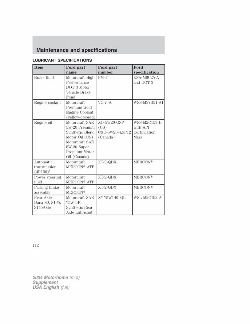
LUBRICANT SPECIFICATIONS
Item Ford part
name
Ford part
number
Ford
specification
Brake fluid Motorcraft HighPerformanceDOT 3 MotorVehicle BrakeFluid
PM-1 ESA-M6C25-Aand DOT 3
Engine coolant MotorcraftPremium GoldEngine Coolant(yellow-colored)
VC-7–A WSS-M97B51-A1
Engine oil Motorcraft SAE5W-20 PremiumSynthetic BlendMotor Oil (US)Motorcraft SAE5W-20 SuperPremium MotorOil (Canada)
XO-5W20-QSP(US)CXO-5W20–LSP12(Canada)
WSS-M2C153-Hwith APICertificationMark
Automatictransmission(4R100)1
MotorcraftMERCON� ATF
XT-2-QDX MERCON�
Power steeringfluid
MotorcraftMERCON� ATF
XT-2-QDX MERCON�
Parking brakeassembly
MotorcraftMERCON�
XT-2-QDX MERCON�
Rear AxleDana 80, S135,S145Axle
Motorcraft SAE75W-140Synthetic RearAxle Lubricant
XY-75W140–QL WSL-M2C192-A
2004 Motorhome (mot)SupplementUSA English (fus)
Maintenance and specifications
112
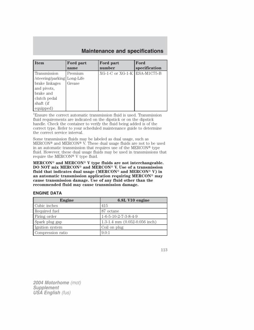
Item Ford part
name
Ford part
number
Ford
specification
Transmission/steering/parkingbrake linkagesand pivots,brake andclutch pedalshaft (ifequipped)
PremiumLong-LifeGrease
XG-1-C or XG-1-K ESA-M1C75-B
1Ensure the correct automatic transmission fluid is used. Transmissionfluid requirements are indicated on the dipstick or on the dipstickhandle. Check the container to verify the fluid being added is of thecorrect type. Refer to your scheduled maintenance guide to determinethe correct service interval.
Some transmission fluids may be labeled as dual usage, such asMERCON� and MERCON� V. These dual usage fluids are not to be usedin an automatic transmission that requires use of the MERCON� typefluid. However, these dual usage fluids may be used in transmissions thatrequire the MERCON� V type fluid.
MERCON� and MERCON� V type fluids are not interchangeable.DO NOT mix MERCON� and MERCON� V. Use of a transmissionfluid that indicates dual usage (MERCON� and MERCON� V) inan automatic transmission application requiring MERCON� maycause transmission damage. Use of any fluid other than therecommended fluid may cause transmission damage.
ENGINE DATA
Engine 6.8L V10 engine
Cubic inches 415Required fuel 87 octaneFiring order 1-6-5-10-2-7-3-8-4-9Spark plug gap 1.3-1.4 mm (0.052-0.056 inch)Ignition system Coil on plugCompression ratio 9.0:1
2004 Motorhome (mot)SupplementUSA English (fus)
Maintenance and specifications
113
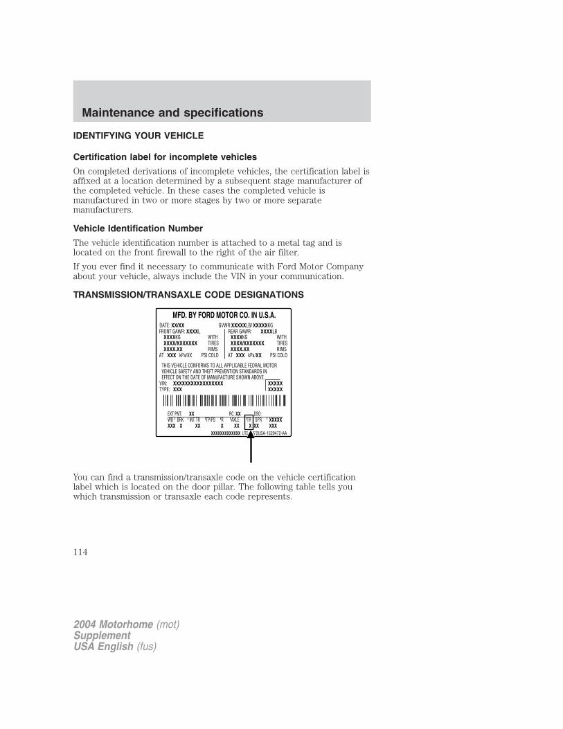
IDENTIFYING YOUR VEHICLE
Certification label for incomplete vehicles
On completed derivations of incomplete vehicles, the certification label isaffixed at a location determined by a subsequent stage manufacturer ofthe completed vehicle. In these cases the completed vehicle ismanufactured in two or more stages by two or more separatemanufacturers.
Vehicle Identification Number
The vehicle identification number is attached to a metal tag and islocated on the front firewall to the right of the air filter.
If you ever find it necessary to communicate with Ford Motor Companyabout your vehicle, always include the VIN in your communication.
TRANSMISSION/TRANSAXLE CODE DESIGNATIONS
You can find a transmission/transaxle code on the vehicle certificationlabel which is located on the door pillar. The following table tells youwhich transmission or transaxle each code represents.
2004 Motorhome (mot)SupplementUSA English (fus)
Maintenance and specifications
114
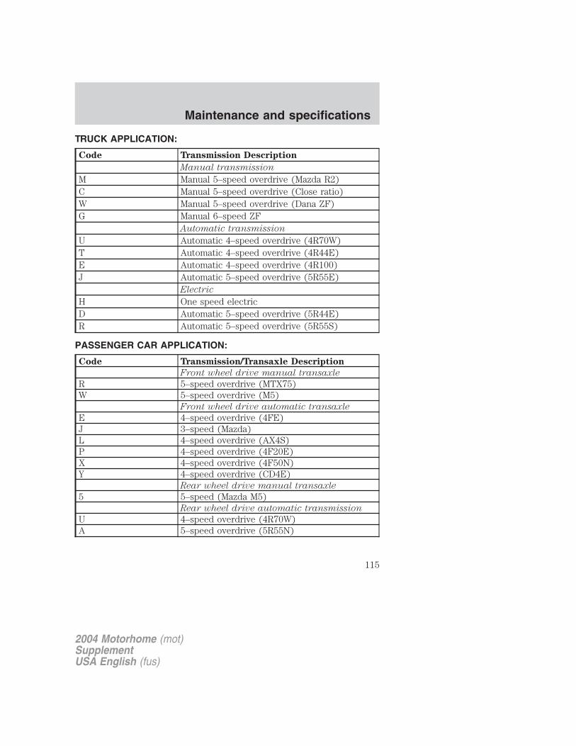
TRUCK APPLICATION:
Code Transmission Description
Manual transmission
M Manual 5–speed overdrive (Mazda R2)C Manual 5–speed overdrive (Close ratio)W Manual 5–speed overdrive (Dana ZF)G Manual 6–speed ZF
Automatic transmission
U Automatic 4–speed overdrive (4R70W)T Automatic 4–speed overdrive (4R44E)E Automatic 4–speed overdrive (4R100)J Automatic 5–speed overdrive (5R55E)
Electric
H One speed electricD Automatic 5–speed overdrive (5R44E)R Automatic 5–speed overdrive (5R55S)
PASSENGER CAR APPLICATION:
Code Transmission/Transaxle Description
Front wheel drive manual transaxle
R 5–speed overdrive (MTX75)W 5–speed overdrive (M5)
Front wheel drive automatic transaxle
E 4–speed overdrive (4FE)J 3–speed (Mazda)L 4–speed overdrive (AX4S)P 4–speed overdrive (4F20E)X 4–speed overdrive (4F50N)Y 4–speed overdrive (CD4E)
Rear wheel drive manual transaxle
5 5–speed (Mazda M5)Rear wheel drive automatic transmission
U 4–speed overdrive (4R70W)A 5–speed overdrive (5R55N)
2004 Motorhome (mot)SupplementUSA English (fus)
Maintenance and specifications
115
A
ABS (see Brakes) .......................24Air cleaner filter .................95, 109Ambulance packages ....................5Antifreeze(see Engine coolant) ..................73Anti-lock brake system(see Brakes) ................................24Automatic transmission
driving an automaticoverdrive ...................................28fluid, adding ..............................92fluid, checking ..........................92fluid, refill capacities ..............110fluid, specification ..................113
Axlelubricant specifications ..112–113refill capacities ........................110
B
Battery .........................................71acid, treating emergencies .......71jumping a disabled battery ......52maintenance-free ......................71replacement, specifications ...109servicing ....................................71
Brakes ....................................23, 25anti-lock .....................................24anti-lock brake system (ABS)warning light .............................25fluid, checking and adding ......91fluid, refill capacities ..............110fluid, specifications .........112–113lubricant specifications ..112–113shift interlock ............................27
Bulbs ............................................15
C
Calculating load ..........................33
Capacities for refilling fluids ....110Changing a tire ...........................48Cleaning your vehicle
engine compartment ................66wheels ........................................66
Coolantchecking and adding ................73refill capacities ..................77, 110specifications ..................112–113
Cruise control(see Speed control) ....................17
Customer Assistance ..................39Ford Extended Service Plan ...58Getting assistance outside theU.S. and Canada .......................62Getting roadside assistance .....39Getting the service you need ..57Ordering additional owner’sliterature ...................................63The Dispute SettlementBoard .........................................59Utilizing theMediation/ArbitrationProgram .....................................62
D
Daytime running lamps(see Lamps) ................................14
Dipstickautomatic transmission fluid ...92engine oil ...................................69
Doorslubricant specifications ..........112
Driveline universal joint andslip yoke ......................................94
Driving under specialconditions ....................................31
through water ...........................31
2004 Motorhome (mot)SupplementUSA English (fus)
Index
116
E
Emergencies, roadsidejump-starting ............................52
Emission control system ............88Engine ................................113–114
cleaning .....................................66coolant .......................................73fail-safe coolant ........................77idle speed control .....................71lubrication specifications 112–113refill capacities ........................110service points ............................68starting after a collision ...........40
Engine block heater ...................23
Engine oil ....................................69checking and adding ................69dipstick ......................................69filter, specifications ..........70, 109recommendations .....................70refill capacities ........................110specifications ..................112–113
Exhaust fumes ............................23
F
Fail safe cooling ..........................77
Fluid capacities .........................110
Fuel ..............................................79calculating fuel economy .........84capacity ...................................110choosing the right fuel .............81comparisons with EPA fueleconomy estimates ...................87detergent in fuel .......................82filling your vehicle withfuel .......................................79, 85filter, specifications ..........82, 109fuel pump shut-off switch .......40improving fuel economy ..........84
octane rating .............81, 113–114quality ........................................81running out of fuel ...................82safety information relating toautomotive fuels .......................79
Fuses ......................................41–42
G
Gas mileage(see Fuel economy) ...................84
Gauges .........................................11
GAWR(Gross Axle Weight Rating) .......31
calculating .................................33definition ...................................31driving with a heavy load ........31location ......................................31
GVWR(Gross Vehicle Weight Rating) ..31
calculating ...........................31, 33definition ...................................31driving with a heavy load ........31location ......................................31
H
Hazard flashers ...........................40
Headlamps ...................................14daytime running lights .............14flash to pass ..............................15high beam .................................14turning on and off ....................14
I
Ignition .........................20, 113–114
Inspection/maintenance (I/M)testing ..........................................89
2004 Motorhome (mot)SupplementUSA English (fus)
Index
117
Instrument panelcluster ..........................................8lighting up panel andinterior .......................................15
J
Jack ..............................................48positioning .................................48storage .......................................48
Jump-starting your vehicle ........52
K
Keyspositions of the ignition ...........20
L
Lampsdaytime running light ...............14headlamps .................................14headlamps, flash to pass ..........15instrument panel, dimming .....15replacing bulbs .........................15
Lights, warning and indicator ......8anti-lock brakes (ABS) ............25
Load limits .............................31, 33GAWR ........................................31GVWR ........................................31trailer towing ............................31
Lubricant specifications ...112–113
M
Motorcraft parts ..................82, 109
O
Octane rating ..............................81
Oil (see Engine oil) ....................69
P
Parking brake ..............................26Parts (see Motorcraft parts) ....109Power distribution box(see Fuses) .................................45Power steering
fluid, checking and adding ......90fluid, refill capacity ................110fluid, specifications .........112–113
R
Relays ....................................41, 48
Roadside assistance ....................39
S
Safety defects, reporting ............65
Servicing your vehicle ................67
Spark plugs,specifications .............109, 113–114
Special notice ................................5
Specification chart,lubricants ...........................112–113
Speed control ..............................17
Starting your vehicle ............20–22jump starting ............................52
Steering wheeltilting .........................................16
T
Tilt steering wheel ......................16
Tires .......................................48, 96changing ..............................48, 51replacing ....................................49snow tires and chains ............108
2004 Motorhome (mot)SupplementUSA English (fus)
Index
118
tire grades .................................97treadwear ..................................96
Towing .........................................36trailer towing ............................36wrecker ......................................56
Transmission ...............................27brake-shift interlock (BSI) ......27fluid, checking and adding(automatic) ...............................92fluid, refill capacities ..............110lubricant specifications ..112–113
V
Vehicle Identification Number(VIN) ..........................................114
Vehicle loading ......................31, 33
Ventilating your vehicle .............23
W
Warning lights (see Lights) .........8
Water, Driving through ...............31
Windshield washer fluid andwipers ..........................................16
Wrecker towing ...........................56
2004 Motorhome (mot)SupplementUSA English (fus)
Index
119

120