table of contents: section 18 - home | denver water · 2017-05-23 · import gps data for arg use...
TRANSCRIPT

Section 18.0 - CAD to GIS: Creating ARG As-Built Drawings 18.0-1
CA
D S
ta
nd
ar
ds
-
3
rd
E
ditio
n –
N
ov
em
be
r 2
01
6
Section 18.0
Table of Contents: Section 18.0
Overview - Section 18.0 .............................................................................................................. 18.0-3
SHP References ......................................................................................................................... 18.0-3
Remove SHP References ...................................................................................................... 18.0-6
Drawing Properties ..................................................................................................................... 18.0-7
Import GPS Data For ARG Use .................................................................................................. 18.0-8
Manually Changing ARG Attribute layers ............................................................................. 18.0-10
Adding ARG Data ..................................................................................................................... 18.0-12
Placement of Line and Point Symbols ....................................................................................... 18.0-13
Placement of Polygon Symbols ................................................................................................. 18.0-15
Editing ARG Attributes .............................................................................................................. 18.0-16
ARG Layer States ..................................................................................................................... 18.0-17
ARG Drawing Cleanup .............................................................................................................. 18.0-18
Overview - Section 18.1 - CAD to ARG Tool Palettes & ARG Attributes ..................................... 18.1-3
Palette Tools ............................................................................................................................... 18.1-3
Button Descriptions ..................................................................................................................... 18.1-5
ARG Attributes ............................................................................................................................ 18.1-7
Overview - Section 18.2 - ARG Dwgs Capital Projects ................................................................ 18.2-1
Workflow ..................................................................................................................................... 18.2-3
Start a New Drawing ................................................................................................................... 18.2-3
Set Coordinates .......................................................................................................................... 18.2-4
Drawing Properties ..................................................................................................................... 18.2-5
GPS Data (GPS Points) .............................................................................................................. 18.2-5
Connecting to GPS Data (SHP files) ...................................................................................... 18.2-6
Remove SHP References ...................................................................................................... 18.2-7
Differing Coordinate Systems ................................................................................................. 18.2-8
Import GPS Data .................................................................................................................... 18.2-9
XREF Survey/Civil .................................................................................................................... 18.2-11

18.0-2 Section 18.0 - CAD to GIS: Creating ARG As-Built Drawings
CA
D S
ta
nd
ar
ds
-
3
rd
E
ditio
n –
N
ov
em
be
r 2
01
6
Detaching ............................................................................................................................ 18.2-11
Placement of Line and Point Symbols .................................................................................. 18.2-12
Placement of Polygon Symbols ........................................................................................... 18.2-14
Using FDO for References & Tie-in .......................................................................................... 18.2-15
ARG Drawing Cleanup ............................................................................................................. 18.2-15
Overview - Section 18.3 - ARG Dwgs Distribution Engineering ................................................... 18.3-1
Suppporting External Documents ............................................................................................... 18.3-3
Setting Up Sheets ....................................................................................................................... 18.3-4
SHP References ......................................................................................................................... 18.3-5
Remove SHP References ........................................................................................................... 18.3-9
Project Drawing Using Sheet Set Manager ............................................................................... 18.3-11
FDO Base Information .............................................................................................................. 18.3-13
Sketch Waterline ...................................................................................................................... 18.3-14
Adding a Pipe Network ............................................................................................................. 18.3-16
Annotate Pipe Network ............................................................................................................. 18.3-18
Structure Label Styles ............................................................................................................... 18.3-19
Edit Label Text .......................................................................................................................... 18.3-21
Add an Abandoned Pipe Network ............................................................................................. 18.3-23
Quantity Takeoff ....................................................................................................................... 18.3-24
DWF Markups in CAD .............................................................................................................. 18.3-26
Overview - Section 18.4 - Drawing Cleanup Tool for ARG Dwgs ................................................ 18.4-3
Drawing Cleanup Errors ............................................................................................................. 18.4-5
Review Drawing Errors ............................................................................................................... 18.4-7
Fix Drawing Errors ...................................................................................................................... 18.4-9

Section 18.0 - CAD to GIS: Creating ARG As-Built Drawings 18.0-3
CA
D S
ta
nd
ar
ds
-
3
rd
E
ditio
n –
N
ov
em
be
r 2
01
6
Overview - Section 18.0
Internal Use: Full compliance where applicable
Contractor Use: Reference only
At DW there are two types of as-built drawings: one for historical record with the Records and Documents Administration (RDA), and one for posting to GIS with the Asset Recording Group (ARG). Typically Design Drafting and Distribution are the groups to create these drawings. Every project is submitted to RDA but not every project is posted to DW’s GIS system, which should be determined by ARG at the onset of a project.
Use the steps in the following subsections to successfully create the ARG As-built Drawings. The content of these Sections will only contain information as it applies to CAD practices and tools. Other applications used in collaboration with these CAD functions may be captured in some documentation.
See Section 5.0 – Example Sheets, and it’s subsections for specific information related to plan creation
See Section 19.0 – Record As-Built Drawings, and its subsections, for related As-built information
Use the steps in the following subsections to successfully create the applicable As-Builts.
Section 18.1 – CAD to ARG Tool Palettes & ARG Attributes
Section 18.2 – ARG Drawings for Capital Projects
Section 18.3 – ARG Drawings for Distribution Engineering
Section 18.4 – Drawing Cleanup Tool for ARG Drawings
SHP References
GPS points can be imported into drawings as SHP files, these can help determine the project area within the drawing. This is optional to help verify the project location & must be done in AutoCAD Map 3D.
In the Task Pane, on the Display Manager tab, click the Data icon and select Connect to Data…:

18.0-4 Section 18.0 - CAD to GIS: Creating ARG As-Built Drawings
CA
D S
ta
nd
ar
ds
-
3
rd
E
ditio
n –
N
ov
em
be
r 2
01
6
The Data Connect fly-out palette will appear. Choose Add SHP Connection from the list on the left and click the
<SHP> button:
The Open pop-up window will appear. Navigate to the project folders’ GPS location (PTNO/dwg/DIST/GPS/Export). Select ONE of the SHP files (preferably MAIN_VALVE) and click <Open>:
NOTE: The intent of this step is to locate the project area on the screen as a precursor to Querying Data.

Section 18.0 - CAD to GIS: Creating ARG As-Built Drawings 18.0-5
CA
D S
ta
nd
ar
ds
-
3
rd
E
ditio
n –
N
ov
em
be
r 2
01
6
In the Data Connect fly-out palette, click <Connect>; then <Add to Map>:
In Model Space, zoom extents. The newly loaded SHP files should appear as markers elsewhere in the drawing (from where layers are currently loaded):
Using the Zoom/Window command, zoom in on these markers:
Tool Tip: Check Coordinates
Imported SHP files should have the
proper Coordinate System already
assigned.
Location where .layers are
currently loaded
Newly loaded SHP markers =
Project Location
Tool Tip: Easy Querying
Draw a temporary rectangle around the SHP file to make Querying Data easier.
18.0-6 Section 18.0 - CAD to GIS: Creating ARG As-Built Drawings
CA
D S
ta
nd
ar
ds
-
3
rd
E
ditio
n –
N
ov
em
be
r 2
01
6
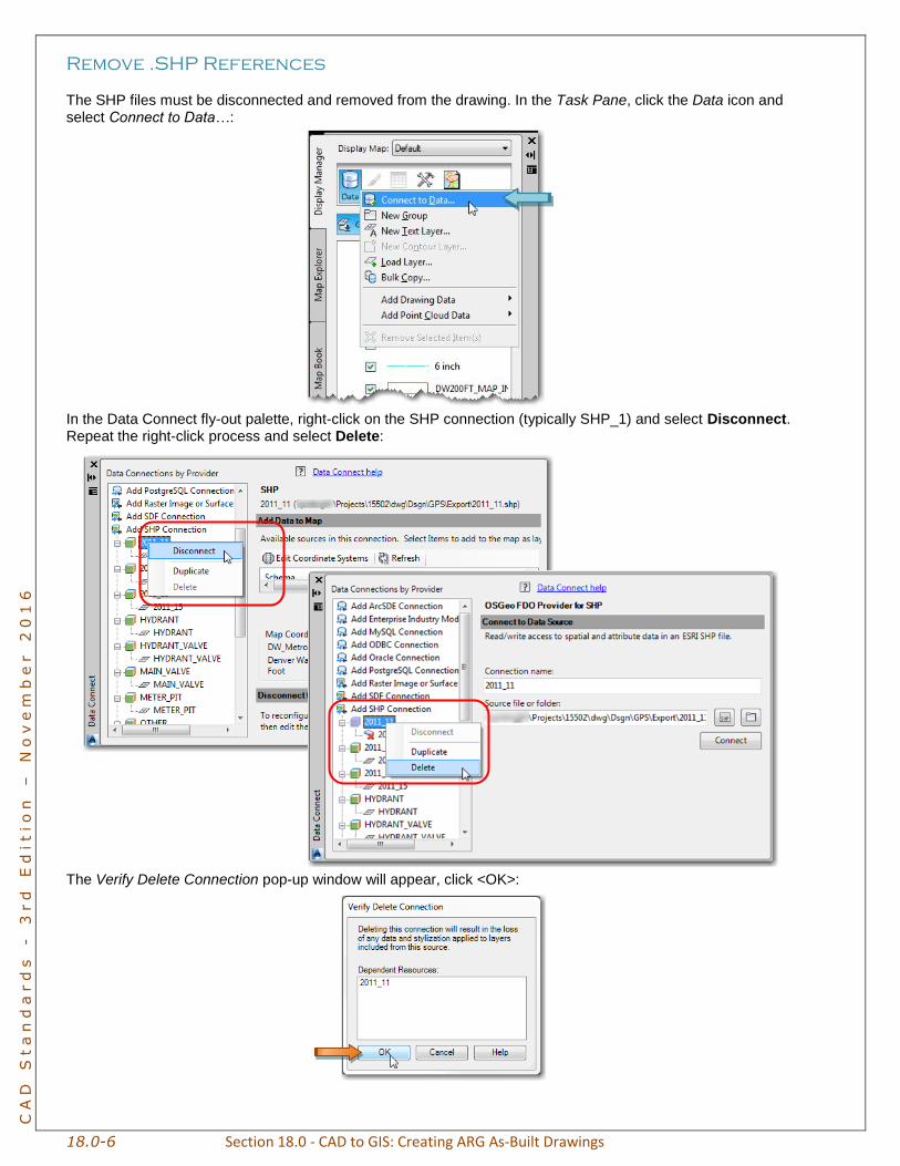
Remove .SHP References
The SHP files must be disconnected and removed from the drawing. In the Task Pane, click the Data icon and select Connect to Data…:
In the Data Connect fly-out palette, right-click on the SHP connection (typically SHP_1) and select Disconnect. Repeat the right-click process and select Delete:
The Verify Delete Connection pop-up window will appear, click <OK>:

Section 18.0 - CAD to GIS: Creating ARG As-Built Drawings 18.0-7
CA
D S
ta
nd
ar
ds
-
3
rd
E
ditio
n –
N
ov
em
be
r 2
01
6
Drawing Properties
The Custom Drawing Properties can be filled in at any time throughout the ARG process. Some information may not be known up front and will need to be added later. To add information internally, click Drawing Properties… on the Quick Tools Tool Palette:
The Drawing Properties dialog window will appear; click the Custom tab and fill in as many values as possible. The information can be found in numerous locations, such as Project Tracker, E-Map, on Inspectors’ notes, or various other places. Once the information has been added, click <OK>:
Examples of information used to populate Drawing Properties

18.0-8 Section 18.0 - CAD to GIS: Creating ARG As-Built Drawings
CA
D S
ta
nd
ar
ds
-
3
rd
E
ditio
n –
N
ov
em
be
r 2
01
6
The Values translate into the ARG Attributes as “global” (highlighted gray) properties:
NOTE: The proper abbreviations MUST be used, see Asset Recording’s Domain_list on SharePoint.
See Asset Recording’s SharePoint site for the most up-to-date documents:
Pipe Rules: Describes pipe and fitting connectivity
Domain List: The proper abbreviations MUST be used
Import GPS Data For ARG use
Inspectors GPS points (SHP files) must be brought into the Project Drawing as ARG Attributes when possible.
On the CAD to ARG Tool Palette, click Import from Files… (shp’s); the Import Location window will appear. Navigate to the project folders’ GPS location (PTNO/dwg/DIST/GPS/Export) and select ALL of the SHP files, then click <OK>:
Tool Tip: Files of type
Make sure ESRI Shapefile (*shp) is selected under Files of type.

Section 18.0 - CAD to GIS: Creating ARG As-Built Drawings 18.0-9
CA
D S
ta
nd
ar
ds
-
3
rd
E
ditio
n –
N
ov
em
be
r 2
01
6
The Import window will appear; in the Saved profiles section click <Load…>:
In the Load Profile pop-up window navigate to \DW CAD\DW CAD Standards; select the
SHPtoBLOCK_NOCS.ipf file and click <Load>:

18.0-10 Section 18.0 - CAD to GIS: Creating ARG As-Built Drawings
CA
D S
ta
nd
ar
ds
-
3
rd
E
ditio
n –
N
ov
em
be
r 2
01
6
The Import pop-up will reappear. Change the Drawing Layers to the appropriate “ARG” layers, click <OK>:
NOTE: Changing layers may be done manually as well.
On the CAD to ARG Tool Palette, click Synchronize Field Values; this will add the fields, (links to the Drawing Properties) to the ARG Attributes (see 18.0-16, this section):
Manually Changing ARG Attribute layers
If drawing layers were not changed in the previous step, they must be changed manually after they are inserted. Using the Properties palette, click the Quick Select
button:
An error window similar to the example below may appear, click <OK>:

Section 18.0 - CAD to GIS: Creating ARG As-Built Drawings 18.0-11
CA
D S
ta
nd
ar
ds
-
3
rd
E
ditio
n –
N
ov
em
be
r 2
01
6
In the Quick Select pop-up window change the Object type to Block Reference, and Properties to Name. Using the Value pull-down, select one of the ARG blocks and click <OK>. In Model Space the chosen ARG Attributes
will be selected (grips will be visible):
On the Properties palette, choose the appropriate layer:
Repeat this step until all ARG Attributes are on the appropriate layers.
ATTENTION The drawing will not post
properly if the ARG Attributes are on the wrong layer.

18.0-12 Section 18.0 - CAD to GIS: Creating ARG As-Built Drawings
CA
D S
ta
nd
ar
ds
-
3
rd
E
ditio
n –
N
ov
em
be
r 2
01
6
Adding ARG Data
The ARG information will be added to the drawing at this time. Once the entire project has been “sketched” into
Model Space, use the ARG tools found on the CAD to ARG Tool Palette [see Section 18.1 – CAD to ARG
Tool Palettes & ARG Attributes] to add additional ARG Attributes as needed (i.e., fittings, hydrants or valves not GPS’d):
Keep these items in mind while adding ARG information:
Water features must be designed in compliance with DW’s Engineering and/or CPPM
ARG’s Pipe Rules and Domain List must be used when placing and populating ARG Attributes, this document can be found on the Asset Recording SharePoint Site
ARG Attributes that were imported from SHP files with GPS points should not be moved if possible; adjust the Collection Method to 300cm in instances where locations have been adjusted (5cm should be maintained otherwise)
For drafting purposes each ARG Attribute shall “break” the line/polyline that represents the water line, exceptions to this include the Access Opening and Fireline Taps – reference the Pipe Rules for
compliance
Pay close attention to referenced details, as these will give exact dimensions, locations, etc.
Do not leave attribute fields blank – for example, if the manufacturer is not clear on valves, use “U” as the value instead
The beginning and ending of projects should always have some kind of fitting/valve (i.e., buttstrap, etc.), and must be indicated with the appropriate ARG Attribute
Blowoff Valve ARG Attributes have TNG (tangential) fittings, others will have SG_FLG_O (single flanged)
Once the CAD to ARG tools have been used to create a line/polyline and/or polygonal the MATCHPROP command can be utilized on similar objects to maintain consistency
o DO NOT use MATCHPROP on ARG Attributes
ARG Attributes that have been placed by mistake (such as Connector Valve instead of Main Valve) must be removed and replaced with the correct ARG Attribute; changing the layer and/or values is not considered sufficient
Always utilize OSNAP’s; choose NODE when snapping to the center of ARG Attributes
Make all “ARG” layers no-plot once finished

Section 18.0 - CAD to GIS: Creating ARG As-Built Drawings 18.0-13
CA
D S
ta
nd
ar
ds
-
3
rd
E
ditio
n –
N
ov
em
be
r 2
01
6
Placement of Line and Point Symbols
Using the XREF’d drawings, FDO base info, .shp files, and other available information, utilize the tools on the
CAD to ARG Tool Palette to recreate the water line alignment, [see Section 15.0 – Tool Palettes]:
NOTE: Pipe Network features are drawn after ARG data on Private Pipe and Contractor installed jobs.
Continue along entire length of project utilizing the CAD to ARG Tool Palette. Pay close attention to the notes in
the original/approved drawings and inspectors notes to add any vertical information:
Using the original/approved drawings and inspectors notes, begin recreating the “new” water line alignment,
including all appurtenances. Be sure to use the appropriate tools\buttons from the CAD to ARG Tool Palette:
New piece of pipe drawn using CAD to
ARG Tool Palette
Pipe Network features
Attribute added with GPS points (SHP files)
Attribute placed manually from CAD to ARG tool palette
Cells filled out according to the
Domain_list
provided by ARG
Where applicable, stations need only to be decimal
numbers. Do not add “STA” or “+” – leave the NULL default if no stationing
Grayed cells indicate fields linked to the
Drawing Properties and are referred to as
“global”. These links can be broken as needed
Previous/Next buttons shows additional cells to be filled
Horizontal bend, do not add stationing to attribute as it is not called out in note. Leave
stationing fields as NULL
Lowering note
Vertical bends; do not add stationing to attributes as it is not called out in note. Leave
stationing fields as NULL

18.0-14 Section 18.0 - CAD to GIS: Creating ARG As-Built Drawings
CA
D S
ta
nd
ar
ds
-
3
rd
E
ditio
n –
N
ov
em
be
r 2
01
6
This example shows the original/approved drawing with the items to be attributed:
The example to the left shows what the ARG attributes will look like within Model Space once they have been populated.

Section 18.0 - CAD to GIS: Creating ARG As-Built Drawings 18.0-15
CA
D S
ta
nd
ar
ds
-
3
rd
E
ditio
n –
N
ov
em
be
r 2
01
6
Placement of Polygon Symbols
On the CAD to ARG Tool Palette, the Polygon Symbols tools will be used to represent vaults, manholes or
other DW structures.
The most commonly used tool will be the Enclosure button and is used primarily for manholes and vaults. For a
full explanation of the tools and buttons see Section 18.1 – CAD to ARG Tool Palettes & ARG Attributes.
When drawings & details indicate the use of a manhole, the exact location in relation to the waterline and valves is very important. Review the detail referenced in the drawing, and place the polygon within the drawing according to the dimensions given. Keep in mind symbols in plan view may not be accurate and may be used solely for graphic representation.
This example on the left shows 2 – 2” AIRV (VAL) and 60” CONC MANHOLE called out with notes
The example on right shows the corresponding detail of the 2” AIRV, place the polygon in drawing according to the detail.
Use the Enclosure button from the CAD to ARG Tool Palette. When prompted for DW Structure Type at the Command Line prompt, type MH_60 (the number
changes per size of manhole).
This example illustrates the polygon placement, with attributes, in Model Space:

18.0-16 Section 18.0 - CAD to GIS: Creating ARG As-Built Drawings
CA
D S
ta
nd
ar
ds
-
3
rd
E
ditio
n –
N
ov
em
be
r 2
01
6
Editing ARG Attributes
There are several ways to edit ARG Attributes, for an explanation of each value (stationing ahead, stationing
back, etc…) [see Section 18.1 – CAD to ARG Tool Palettes & ARG Attributes].
When an ARG Attribute is inserted into the drawing an Edit Attributes window pops up, it is best to fill out
as much information as possible at this point:
Once the ARG Attribute has been placed, one option for editing is the AutoCAD EDIT command. This will bring up a window called Enhanced Attribute Editor. Simply click on the Tag to be updated and type the new information at the Value line:
Another option for editing an ARG Attribute is to click the attribute once (showing only a grip edit) and to edit the information by using the AutoCAD Properties palette.
Tool Tip: Extra Info
Use the <Next> and <Previous> buttons to toggle between multiple attribute fields.
Tool Tip: Redefine
If the Tag and Prompt columns are misaligned REDEFINE the ARG Attribute block within the drawing.

Section 18.0 - CAD to GIS: Creating ARG As-Built Drawings 18.0-17
CA
D S
ta
nd
ar
ds
-
3
rd
E
ditio
n –
N
ov
em
be
r 2
01
6
ARG Layer States
Layer States can be used to manage the ARG layers; Layer States are useful when using the Drawing Cleanup tool as described later in this document.
On the Home tab of the ribbon, on the Layers panel, select the Layer State pull-down and choose Manage Layer States…:
The Layer States Manager pop-up will appear,
click <New…>:
The New Layer State to Save pop-up will appear, type the name in the New layer state name field,
then click <OK>:
The Layer States Manager window will reappear, click
<Close> when finished.
Within Model Space of the ARG drawing turn all layers off except those prefixed with “ARG.”:

18.0-18 Section 18.0 - CAD to GIS: Creating ARG As-Built Drawings
CA
D S
ta
nd
ar
ds
-
3
rd
E
ditio
n –
N
ov
em
be
r 2
01
6
ARG Drawing Cleanup
In order for ARG to post to GIS properly it is critical for them to receive drawings that meet specific
“connectivity” requirements. The Drawing Cleanup Tools [see Section 17.3 – Drawing Cleanup Tools] have been customized to work efficiently with ARG drawings.
NOTE: You must be very cautious with the Drawing Cleanup Tools and review each cleanup action thoroughly before fixing.